Embed Size (px)
Citation preview

The Islamic University of Gaza
Engineering Faculty
Department of Computer Engineering
Fall 2017
ECOM 2013
Khaleel I. Shaheen
Combinational Digital Design
Laboratory Manual
Experiment #9
Multiplexer & Demultiplexer
2
Objectives
• Understanding how to implement functions using multiplexers.
• To study demultiplexer.
Theoretical Background
Multiplexers
In electronics, a multiplexer (or mux) is a device that selects one of several analog or digital
input signals and forwards the selected input into a single line. A multiplexer of 2n inputs has n
select lines, which are used to select which input line to send to the output.
• A 2n-to-1 multiplexer sends one of 2n input lines to a single output line.
• A multiplexer has two sets of inputs:
o 2n data input lines
o n select lines, to pick one of the 2n data inputs
• The mux output is a single bit, which is one of the 2n data inputs.
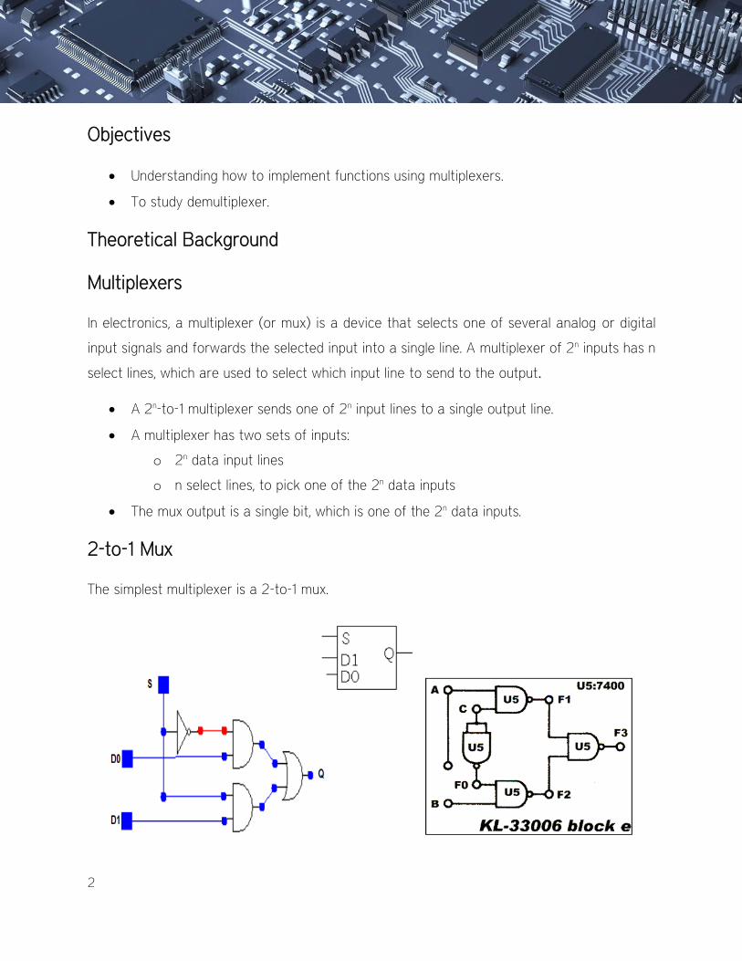
2-to-1 Mux
The simplest multiplexer is a 2-to-1 mux.
3
Q = S'D0 + SD1
The select bit S controls which of the data bits D0-D1 is chosen:
• If S=0, then D0 is the output (Q=D0).
• If S=1, then D1 is the output (Q=D1).
Here is a full truth table for this 2-to-1 mux,
S D1 D0 Q
0 0 0 0
0 0 1 1
0 1 0 0
0 1 1 1
1 0 0 0
1 0 1 0
1 1 0 1
1 1 1 1
Here is another kind of abbreviated truth table.
S Q
0 D0
1 D1
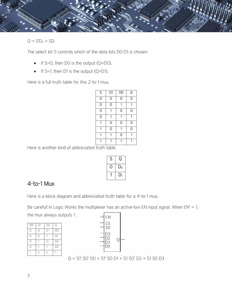
4-to-1 Mux
Here is a block diagram and abbreviated truth table for a 4-to-1 mux.
Be careful! In Logic Works the multiplexer has an active-low EN input signal. When EN’ = 1,
the mux always outputs 1.
EN' S1 S0 Q
0 0 0 D0
0 0 1 D1
0 1 0 D2
0 1 1 D3
1 x x 1
Q = S1' S0' D0 + S1' S0 D1 + S1 S0' D2 + S1 S0 D3
4
Implementing functions with multiplexers:
Muxes can be used to implement arbitrary functions. For a function of n variables follow these
steps:
1. Select the type of Mux [2n-1-to-1].
2. Select (n-1) as selection line.
3. The other input connects as input.
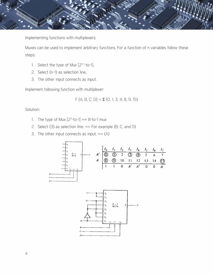
Implement following function with multiplexer:
F (A, B, C, D) = Σ (0, 1, 3, 4, 8, 9, 15)
Solution:
1. The type of Mux [23-to-1] == 8-to-1 mux
2. Select (3) as selection line. == For example (B, C, and D)
3. The other input connects as input. == (A)
5
In terms of B
I0 I1 I2 I3 I4 I5 I6 I7
B' 0 1 2 3 8 9 10 11
B 4 5 6 7 12 13 14 15
1 B' 0 B' B' B' 0 B
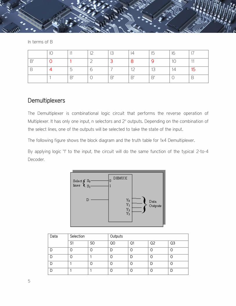
Demultiplexers
The Demultiplexer is combinational logic circuit that performs the reverse operation of
Multiplexer. It has only one input, n selectors and 2n outputs. Depending on the combination of
the select lines, one of the outputs will be selected to take the state of the input.
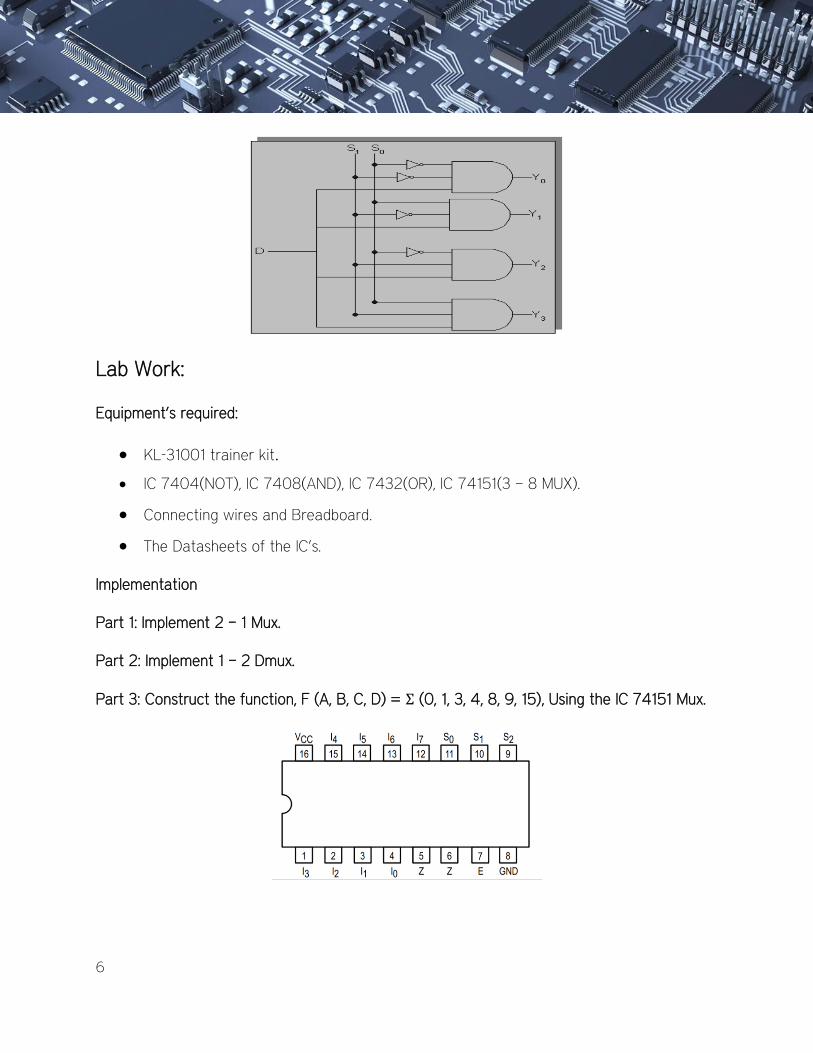
The following figure shows the block diagram and the truth table for 1x4 Demultiplexer.
By applying logic '1' to the input, the circuit will do the same function of the typical 2-to-4
Decoder.
Data Selection Outputs
S1 S0 Q0 Q1 Q2 Q3
D 0 0 D 0 0 0
D 0 1 0 D 0 0
D 1 0 0 0 D 0
D 1 1 0 0 0 D
6
Lab Work:
Equipment’s required:
• KL-31001 trainer kit.
• IC 7404(NOT), IC 7408(AND), IC 7432(OR), IC 74151(3 – 8 MUX).
• Connecting wires and Breadboard.
• The Datasheets of the IC’s.
Implementation
Part 1: Implement 2 – 1 Mux.
Part 2: Implement 1 – 2 Dmux.
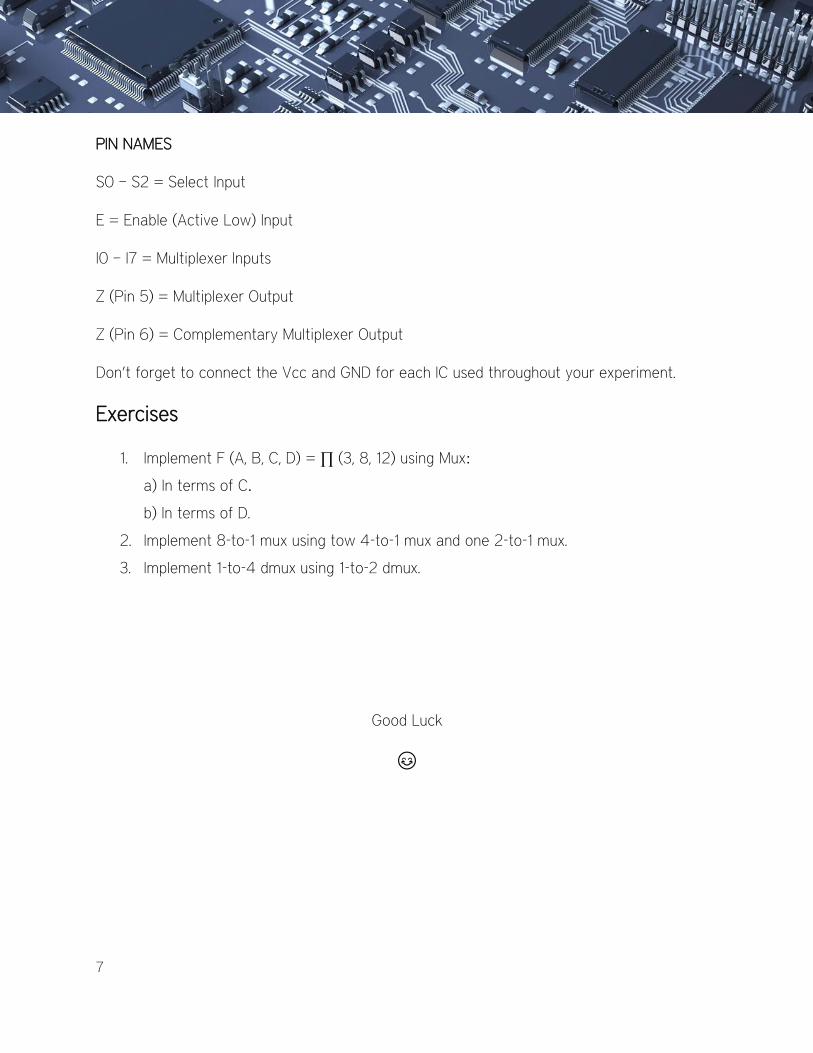
Part 3: Construct the function, F (A, B, C, D) = Σ (0, 1, 3, 4, 8, 9, 15), Using the IC 74151 Mux.
7
PIN NAMES
S0 – S2 = Select Input
E = Enable (Active Low) Input
I0 – I7 = Multiplexer Inputs
Z (Pin 5) = Multiplexer Output
Z (Pin 6) = Complementary Multiplexer Output
Don’t forget to connect the Vcc and GND for each IC used throughout your experiment.
Exercises
1. Implement F (A, B, C, D) = ∏ (3, 8, 12) using Mux:
a) In terms of C.
b) In terms of D.
2. Implement 8-to-1 mux using tow 4-to-1 mux and one 2-to-1 mux.
3. Implement 1-to-4 dmux using 1-to-2 dmux.
Good Luck
😊