Embed Size (px)
Citation preview

International Journal of Heat and Mass Transfer 74 (2014) 292–305
Contents lists available at ScienceDirect
International Journal of Heat and Mass Transfer
journal homepage: www.elsevier .com/locate / i jhmt
Comparison of winglet-type vortex generators periodically deployed in aplate-fin heat exchanger – A synergy based analysis
http://dx.doi.org/10.1016/j.ijheatmasstransfer.2014.03.0150017-9310/� 2014 Elsevier Ltd. All rights reserved.
⇑ Corresponding author. Address: Indian Institute of Technology Guwahati,Guwahati 781039, India (On deputation). Tel.: +91 361 2582005/2690401.
E-mail address: [email protected] (G. Biswas).
Pankaj Saha, Gautam Biswas ⇑, Subrata SarkarDepartment of Mechanical Engineering, Indian Institute of Technology Kanpur, Kanpur 208016, India
a r t i c l e i n f o a b s t r a c t
Article history:Received 20 April 2012Received in revised form 29 January 2014Accepted 3 March 2014Available online 12 April 2014
Keywords:Vortex generatorsEnhanced heat transferLongitudinal vorticesField synergy principle
The objective of the present investigation is to assess the performance of a plate-fin heat exchanger withan emphasis on acquiring fundamental understanding of the relation between local flow behavior andheat transfer augmentation mechanism. Numerical simulations are performed in a rectangular channelcontaining built-in longitudinal vortex generators on the bottom wall arranged periodically both in thestreamwise and spanwise directions. Two types of vortex generators, namely, rectangular winglet pair(RWP) and delta-winglet pair (DWP) with two different flow arrangements, common-flow-up (CFU)and common-flow-down (CFD) have been explored to assess the influence of shape and flow arrange-ments on heat transfer enhancement. The basic mechanisms of flow structure and heat transfer charac-teristics have been examined with the help of secondary velocity vectors, streamlines, and temperaturecontours. Additionally, the mechanism of the local heat transfer augmentation has been explained using anovel concept called the field synergy principle. The performance of the vortex generators has been com-pared based on integral quantities such as Nusselt number, pressure loss, performance evaluation factorand domain averaged synergy angle. The computations reveal enhanced mixing of fluid between the walllayer and the core due to strong secondary flows produced by vortex generators. The performance anal-ysis indicates that the RWP is more effective in terms of heat transfer enhancement as compared to DWP.The field synergy analysis has shown that the sites with higher Nusselt number are associated with smal-ler synergy angle or better coordination between the velocity vector and the temperature gradient.
� 2014 Elsevier Ltd. All rights reserved.
1. Introduction
The light-weight and highly efficient heat exchangers requiresome special enhancement technique for heat transfer improve-ment. In practice, the gas-side surfaces of a heat exchanger are re-quired to be specially designed to offset the poor heat transfercoefficient on the gas-side. One of the heat transfer enhancementtechniques is introduction of longitudinal vortices in the flow fieldby using specially designed surfaces. This is a deliberate modifica-tion of heat transfer surfaces, where longitudinal vortex generators(LVGs), such as wings or winglets in the form of rectangular or del-ta shapes are mounted on the heat transfer surfaces. The introduc-tion of LVGs increases the heat transfer area, and also provides anadditional heat transfer mechanism in the form of swirling theflow. The heat transfer benefit due to swirling motion exceedsthe benefit obtained due to increase in heat transfer area (seeFig. 1).
The literature survey reveals the existence of a considerableamount of research on the topic of heat transfer enhancementusing longitudinal vortex generators. A comprehensive coverageof the different aspects of heat transfer surfaces with vortex gener-ators has been systematically presented by Jacobi et al. [1] and byFiebig [2] in their review articles. Another recent review article ofBiswas et al. [3] has focused on the present state-of-the-art of aug-mentation techniques for heat exchanger surfaces using longitudi-nal vortex generators. The authors [3] have systematicallyaddressed the different forms of protrusions, types of flow config-urations and flow conditions, and strategies related to optimizedheat transfer enhancement with minimal flow losses. The pioneer-ing experimental investigation of Tiggelbeck et al. [4,5] revealedthe enhancement in heat transfer of heat exchanger surfaces dueto longitudinal vortices generated by wings or winglet pairs inthe form of delta or rectangular shape. Subsequently, they studiedthe flow structure and heat transfer in a channel with single anddouble rows of vortex generators in aligned and staggered arrange-ments. The results showed that the Nusselt number at the secondrow was dependent on the distances between the rows and be-came highest for a distance of 7–10 channel heights. Moreover,

Nomenclature
H channel heightLp longitudinal pitchBp lateral pitchh height of wingletl chord length of wingletp pressuret dimensional timeUav average streamwise velocityRe Reynolds number, (UavH/m)Pr Prandtl numberT dimensional temperatureT0 reference temperatureNu Nusselt numberCf friction coefficientf apparent friction factoru, v, w streamwise, wall-normal and spanwise components of
velocityx, y, z streamwise, wall-normal and spanwise coordinatesRWP rectangular winglet pair
DWP delta winglet pairCFD common-flow-downCFU common-flow-up
Greek symbolsm kinematic viscosity of the fluida local intersection angle or synergy angleq densitys nondimensional time, (tUav/H)h nondimensional temperature, (T/T0)b angle of attack of winglet
Subscriptsw wallb bulk valueav average valuem mean valueo reference value
P. Saha et al. / International Journal of Heat and Mass Transfer 74 (2014) 292–305 293
the experimental results pointed out that pressure loss and heattransfer enhancement is highly sensitive to the angle of attack ofthe vortex generators. One notable experimental work was pur-sued by Gentry et al. [6] which observed similar trends of improve-ment in heat transfer performance of a plate-fin heat exchangerusing delta wing vortex generators.
Biswas and Chattopadhyay [7], numerically examined the flowstructure in laminar a channel flow with built-in wing type vortexgenerators and obtained 34% increase in the spanwise averagedNusselt number even at the exit. Biswas et al. [8] analyzed flowstructure and heat transfer in a fin-tube heat exchanger withbuilt-in delta winglet pairs. A punched-out delta winglet pair withan aspect ratio of 2 was located behind each tube at an angle of at-tack of 45�. At a Reynolds number of 500, a local heat transferenhancement of more than 240% was reported at a location about12 times the channel height downstream of the inlet. Furthermore,Biswas et al. [9] performed a comparison of the numerical investi-gation with its experimental counterpart to study the flow struc-ture and heat transfer effects of longitudinal vortices behind adelta winglet attached in a fully developed laminar channel flow.Sohankar et al. [10] numerically investigated the effect of rectan-gular vortex generators on heat transfer enhancement with anemphasis on the flow structure in a plate-fin heat exchanger. Theirobservations pointed out the effects of the angle of attack andReynolds number on heat transfer enhancement. Recently, acomprehensive numerical investigation on improvement of heattransfer performance of a plate-fin heat exchanger was conductedby Wu et al. [11], employing both delta and rectangular wingletpairs as vortex generators. The mechanism of heat transfer aug-mentation was examined. Additionally, an extensive parametricstudy was carried out to quantify the effect of shape and type ofthe vortex generator, angle of attack and height of the winglet onheat transfer and pressure loss for a wide range of Reynolds num-bers. Apart from these, recent articles such as those by Tian et al.[12] and Promvonge et al. [13] have also clearly examined theeffectiveness of longitudinal vortex generators in heat transferenhancement.
In practical applications, the ratio of gas-side channel length tochannel height is at least 30 for compact heat exchangers. Thislarge ratio requires several rows of vortex generators for sufficientheat transfer enhancement. Such a configuration shows periodi-cally repeating flow conditions at some downstream rows of
vortex generators. This situation is referred to as periodically fullydeveloped flow [14].
Both, numerical and experimental studies in a channel withperiodically arranged rectangular winglets in the laminar regimewere discussed by Fiebig [2]. The experimental study noticedself-sustained oscillatory flow at a Reynolds number of 150 basedon channel height for the winglet with an angle of attack ofb ¼ 45�. The critical Reynolds number is an order of magnitude be-low the critical Re of plane channel flow. The results also pointedout that the critical Reynolds number increased with decrease inboth the winglet height and the angle of attack. In ref [2], thenumerical investigation focused on steady and self-sustained oscil-latory flow situations in a periodic module or element using boththe symmetric and periodic boundary conditions in the spanwisedirection. They found a global heat transfer enhancement of 50%over plane channel value at Re = 175 and angle of attack ofb = 45� for steady flow. In another similar work of Fiebig et al.[15], eight different winglet configurations obtained from the com-bination of inline or staggered, symmetric or parallel and wingletson one or both walls were compared for flows in a periodic channelwith built-in rectangular winglets. On the other hand, Lau et al.[16] carried out an experimental study for transition to a turbulentregime for the same geometric configurations.
Available literature reports limited research articles related toperiodical array of longitudinal vortex generators, and mainly con-siders rectangular winglets as vortex generators. In order to haveoptimal heat exchanger configuration, one has to examine variousparameters in terms of shape of the winglets, flow configurations,the effects of domain size, the ratio of height of vortex generatorsto channel height, the gap between the winglets, etc. Therefore, thepresent authors feel that work involving different types of vortexgenerators with different types of flow arrangements may addvaluable input towards efficient compact heat exchanger design.
The aim of the present study is to carry out a numerical inves-tigation on the performance of plate-fin heat exchangers with rowsof winglets as vortex generators. In particular, a comparative studyhas been undertaken for two types of vortex generators, rectangu-lar winglet pair (RWP) and delta winglet pair (DWP) with twotypes of flow configurations, common-flow-down (CFD) and com-mon-flow-up (CFU). The periodic nature in the flow field allows forconsideration of only one periodic element of the channel as thecomputational domain. Therefore, we compute periodically fully

Fig. 1. Identification of a periodic heat exchanger element: (a) schematic of plate-fin heat exchanger; (b) 2-D array of vortex generators attached on the surface ofcompact heat exchanger (length L, width B, height H); (c) periodic surface elementas a modular computational domain (longitudinal pitch Lp, lateral pitch Bp, channelheight H).
294 P. Saha et al. / International Journal of Heat and Mass Transfer 74 (2014) 292–305
developed flow in this element. From the computed velocity andtemperature fields, local and global friction, flow losses and heattransfer enhancement have been estimated. The cross streamvelocity fields and the local Nusselt number distribution on theplates are analyzed to understand the flow physics and heat trans-fer in detail. The spanwise averaged Nusselt number and frictioncoefficient are calculated and compared with the values obtainedfor the plane channel without any obstacle in order to appreciatethe effectiveness of vortex generators.
It is well known from literature that the secondary flowgenerated by longitudinal vortex generators enhances fluid mixing,modifies boundary layer and induces flow oscillation, therebypromoting convective heat transfer. Recently, Guo et al. [17]proposed a novel concept called field synergy principle (FSP) toprovide an alternative approach to reveal the mechanism of
enhanced convective heat transfer. According to the field synergyprinciple, the heat transfer enhancement is due to the reductionof the intersection angle between the velocity vector and temper-ature gradient of the transport process. This idea was furthercorroborated by Tao and co-workers [18,19], who verified andsuccessfully implemented the concept on a wide range offundamental and industrial heat transfer related applications.The mathematical descriptions of FSP are well documented inrelevant references [17–20] and thus will not be reported here.In the current study, heat transfer enhancement has beenexplained on the basis of FSP.
2. Problem formulation
2.1. Computational domain and vortex generator geometry
As mentioned earlier, modular geometry allows for the compu-tation to be done in a three-dimensional periodic channel which isformed by two neighboring fins of a compact plate-fin heat ex-changer. The obstacles, in the form of a rectangular winglet pair(RWP) or a delta-winglet pair (DWP) are attached on the bottomwall of the channel at an angle of attack with the main flow direc-tion. The computational domain and the associated geometricaldimensions of the channel with built-in winglet pairs of differenttypes are shown in Fig. 2. The flow is described in a rectangularCartesian coordinate system (x,y,z), in which x, y, z representstreamwise, wall normal and spanwise directions, respectively.Various flow configurations are possible for this arrangement ofthe vortex generators with respect to their relative positioninginside the channel. In the present study, two different types of con-figurations have been deployed, common-flow-down (CFD) andcommon-flow-up (CFU) as shown in Fig. 2. Common-flow-down(Fig. 2(a)) means that the flow field between the two vortices isdirected towards the surface on which the vortex generators aremounted. Common-flow-up (Fig. 2(b)) signifies that the vortexgenerators in a pair are placed such that the resulting vorticesset up counter rotating motion so as to move the fluid betweenthem away from the surface on which they are mounted.
The following geometrical dimensions of the computational do-main have been used in the present investigation. All dimensionshave been expressed in terms of channel height H (i.e., the distancebetween two fins). These dimensions are typical of a practicalplate-fin heat exchanger.
The channel has the following dimensions.
Longitudinal pitch, channel length (Lp): 5H.Lateral pitch, channel width (Bp): 4H.Fin pitch, channel height: H.
To keep the comparison meaningful, the surface areas of thetwo types of winglet pairs have been kept equal for the presentstudy. The relevant dimensions of the two types of vortex genera-tors are summarized in Table 1.
The distance of the leading edge of the winglet pair from the en-trance of the channel (S) is fixed at 2.0. The minimum gap betweenthe winglet pairs (e) is kept at 0.3. The thickness of the winglet hasbeen assumed to be zero for simplification. The angle of attack (b)of the obstacles is kept fixed at 45� for all cases. Both the configu-rations have the same wall to winglet surface area ratio of 10. Theblockage (ratio of projected surface area of winglet pair on thecross flow plane and the area of the cross flow plane) of the chan-nel formed by the two types of winglets for this specific angle ofattack is same (0.35). It is to be mentioned that usually thepressure loss or form drag is proportional to the blockage or theprojected area.

βh
l
Bp
H
Lp
Bp
H
Lp
β
l
h
e
Se
S
FlowFlow
z
x
z
x
(a) (b)
(d)(c)
y
z
x yx
z
Fig. 2. Computational domain with associated geometrical parameters: (a) channel with rectangular winglet pair; (b) channel with delta winglet pair; (c) common-flow-down configuration; (d) common-flow-up configuration.
Table 1Parameters related to the winglet pairs.
Parameters RWP DWP
Chord length of winglet, l 2H 2HHeight of winglet, h 0.5H HAspect ratio 1 2
P. Saha et al. / International Journal of Heat and Mass Transfer 74 (2014) 292–305 295
2.2. Governing equations
In many heat exchanger applications the flow becomes laminardue to low air velocity and small fin pitch. Therefore, the flow isconsidered to be three dimensional and laminar. The air istreated as an incompressible fluid with constant thermo-physicalproperties.
The conservation equations, describing the flow and the tem-perature fields are the continuity equation, the time-dependentNavier–Stokes equations and the energy equation. In Cartesian ten-sor notation the non-dimensional conservative form of equationsare as follows:
Continuity:
@ui
@xi¼ 0 ð1Þ
Momentum:
@ui
@sþ @ðuiujÞ
@xj¼ � @p
@xiþ 1
Re@2ui
@x2j
ð2Þ
Energy:
@h@sþ @ðhujÞ
@xj¼ 1
RePr@2h
@x2j
ð3Þ
Here ui = u, v, w stands for Cartesian velocity components in x, y andz directions respectively. In the above equations, velocities have
been nondimensionalized by the average streamwise velocity Uav
and the pressure by qU2av . All lengths are made dimensionless with
the channel height H. The dimensionless temperature is defined as,h ¼ T
T0with T0 being the reference temperature. The time is normal-
ized as s = tUav/H. The above normalization leads to the followingnondimensional parameters: Reynolds number Re = UavH/m and Pra-ndtl number Pr = m/a, where m and a are kinematic viscosity andthermal diffusivity respectively.
2.3. Boundary conditions
Periodic boundary conditions for both velocity and temperatureare enforced at the inflow and outflow sections, where the velocityand temperature fields in these planes evolve during the calcula-tion. On the other hand, one can choose symmetric or periodicboundary conditions at the lateral side planes. Symmetric bound-ary condition may restrict the unsteady vortices moving throughthe lateral boundaries and inhibit self-sustained oscillation, in con-trast to periodic boundary condition. But the winglet arrangementfor the present study results in symmetric flow configuration atside planes. Therefore, symmetry conditions for all variables areimposed at the side boundaries as suggested in [15]. The no-slipboundary condition is used at all solid walls including the wingletsurfaces by setting all components of velocity to zero. The details ofthe kinematic boundary condition on the surface of vortex genera-tors are discussed elsewhere in [8].
In the present study, the implementation of the periodic bound-ary condition for pressure in the streamwise direction follows theprocedure as outlined in Patankar et al. [21].
For periodically fully developed thermal field, the dimension-less temperature profile, h�hw
hb�hwidentically repeats itself from mod-
ule to module. Here, hw and hb refer to non-dimensional walltemperature and the bulk temperature at any axial cross sectionrespectively. The aforementioned periodic temperature boundary

296 P. Saha et al. / International Journal of Heat and Mass Transfer 74 (2014) 292–305
condition has been used by Patankar et al. [21]. On the solid walland winglet surfaces, uniform wall temperature is assumed andequals twice the reference temperature T0. Therefore, the valueof imposed non-dimensional wall temperature is hw = 2.
The local Nusselt number based on channel height is calculatedas: Nuðx; yÞ ¼ hH
j ¼ð@h=@zÞwallðhb�hwÞ .
The local friction coefficient is calculated as: Cf ¼ sw
ðq=2ÞU2av
.
2.4. Solution method
The three dimensional, unsteady and full Navier–Stokesequations along with the prescribed boundary conditions havebeen solved numerically using a modified version of Marker andCell (MAC) algorithm [22,23]. The solution procedure is welldocumented in an earlier investigation by Biswas et al. [24].
Air is considered as the working fluid with Prandtl number 0.71.The simulation has been performed for Reynolds number (based onaverage axial velocity and channel height) of 50 6 Re 6 200, keep-ing angle of attack of the vortex generators fixed at b = 45�, for allfour configurations. The flow becomes steady or oscillatorydepending on the Reynolds numbers.
2.5. Grid independence test and validation
Spatial resolution and numerical accuracy are important issuesin the calculation of complex flows. The longitudinal vortexgenerators modulate the velocity and temperature profiles tocomplex shapes. Thus high resolution is needed to accuratelyrepresent the flow structures. Grid refinement studies have beenconducted for the channel with RWP in common-flow-down con-figuration at Re = 175. Three different grid systems (Grid-mesh I:52 � 16 � 42), (Grid-mesh II: 73 � 22 � 59) and (Grid-mesh III:87 � 26 � 70) have been compared. In the foregoing specificationof grids, the numbers in the brackets represent grid sizes in x, yand z directions, respectively. The cell width in x and z directionsare same and are 1.4 times the cell width in the y direction. Thediscrepancy of span-averaged Nusselt number and streamwisefriction coefficient for Grid-mesh II and Grid-mesh III are 1.5%and 2.5% respectively. The deviation in Nusselt number is muchless because the temperature profiles are much less distorted thanthe velocity profiles. Simulations by Fiebig [2] for a similar flowconfiguration and a given grid-mesh revealed that a 3% discrep-ancy in results for heat transfer and flow losses from extrapolatedgrid-independent solution is an acceptable grid-mesh. All thesubsequent computations are performed using a grid-mesh of73 � 22 � 59. The computational results due to the presentnumerical method have been validated extensively with theirexperimental counterparts in the entry flow region of a rectangu-lar channel with built-in delta winglet [9]. In the current study,the computed Nusselt number enhancement, mean friction coeffi-cient and apparent friction factor averaged for both the channelwalls with reference to plane channel value at Re = 175 have beencompared with numerical results of Fiebig [2], for RWP–CFD con-figurations. Corresponding values of Num/Nu0, Cf/f0 and f/f0 for thepresent computation are 1.66, 1.63 and 3.1 as compared to thecomputational values of 1.6, 1.6 and 3.0 respectively, in Ref. [2].The results show good agreement with those obtained fromavailable literature.
3. Results and discussions
The main objective of the present study is to estimate the influ-ence of the winglet arrangement and winglet type (shape) on theflow structure and the corresponding heat transfer characteristics
for a plate-fin heat exchanger. Thus investigations with two typesof winglet geometry, rectangular winglet pair (RWP) and deltawinglet pair (DWP), along with two types of flow configurationsnamely common-flow-down (CFD) and common-flow-up (CFU)have been conducted. Four different cases have been studied. Forthe purpose of explanation, the cases are read as RWP–CFD,RWP–CFU, DWP–CFD and DWP–CFU respectively. In the case ofcommon-flow-down (CFD) configuration, the winglet pair ismounted in such a way that the transverse distance between theleading edges of the winglet pairs is less than that of the trailingedges. On the other hand, the transverse distance between theleading edges of the winglet pair is more than that of the trailingedges for common-flow-up (CFU) configuration. The analysis isbased on the concept of periodically fully developed flow and ther-mal condition considering a modular periodic element of the origi-nal multi-array plate-fin heat exchanger. The angle of attack is setat 45�. The Reynolds number, based on average axial velocity andchannel height varies in the range of 50–200. The flow conditionbecomes steady or mildly oscillating for this above range of Rey-nolds numbers but remains laminar. In order to obtain an averagedflow field for unsteady flow condition, the instantaneous velocitiesand temperature are time averaged over 3 cycles. In the represen-tation, Nusselt number and frictional loss parameter (apparentfriction factor and friction coefficient) are normalized with theplane channel values at constant wall temperature as Nu0 = 3.77and f0 = 12/Re, respectively.
An effective way to visualize the strong swirling motion gener-ated by the winglet pair is to consider the vector plot of secondaryvelocities on different cross-planes (x = 1, 2, 3 and 4) as shown inFig. 3. A pair of strong counter-rotating longitudinal vortices isclearly visible. In case of common-flow-down configuration asshown in Fig. 3(a) and (c), for the winglet wall (bottom wall,y = 0), the inner region between the vortex cores of two vorticesconstitutes a downwash region (inflow), where the flow is directedtowards the lower channel wall. However, the outer region be-tween the vortex cores and fin edges is an upwash region, whereflow is lifted away from the bottom wall. On the other hand, forcommon-flow-up configurations as shown in Fig. 3(b) and (d),the counter-rotating vortices produce an upwash region (outflow)in the area common to the two vortices on the winglet wall (bot-tom wall, y = 0) and a downwash region between the side surfacesand vortex cores. As expected, the flow in the upwash region islifted away from the lower channel wall and directed towardsthe bottom wall in the down-wash region. Correspondingly, forthe plane wall (top wall, y = 1) in all cases, the flow pattern consti-tutes an opposite terminology with respect to the winglet wall(bottom wall). It appears that the rotational velocities are strongercompared to the mean streamwise velocity close to the longitudi-nal vortex core. The streamwise development reveals that the sec-ondary velocities become gradually weaker downstream due to thediffusion caused by viscosity of the fluid. Moreover, between thedownwash and upwash areas, strong span-wise velocity compo-nents are visible beneath the longitudinal vortex cores. This regionis identified as a sidewash area, where the strong lateral velocitiesmodify transport mechanism between the fluid and the wall. Addi-tionally, down-wash regions promote mixing due to flow impinge-ment towards the wall, while up-wash regions reveal morethermal resistance. It appears from the figure that lateral velocitiesare stronger than the wall normal velocities and sustain overconsiderably larger areas. Interestingly, RWP display strongerswirling motion compared to DWP, especially close to the leadingedge of the winglet and spread over a greater area. In the case ofRWP–CFD, larger down-wash and side-wash regions with arelatively smaller up-wash region are visible, whereas RWP–CFUindicates a significant up-wash region with relatively smaller sidewash areas. However, the side-wash areas associated with DWP
y
zx
12
34
(b) DWP−CFU
12
34
(a) DWP−CFD
12
34
12
43
(c) RWP−CFD (d) RWP−CFU
Fig. 3. Vector plots of secondary velocity in four configurations at cross-sectional planes, x = 1, 2, 3 and 4 (Re = 175,b = 45�).
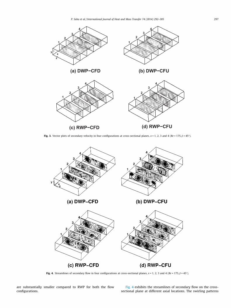
Fig. 4. Streamlines of secondary flow in four configurations at cross-sectional planes, x = 1, 2, 3 and 4 (Re = 175,b = 45�).
P. Saha et al. / International Journal of Heat and Mass Transfer 74 (2014) 292–305 297
are substantially smaller compared to RWP for both the flowconfigurations.
Fig. 4 exhibits the streamlines of secondary flow on the cross-sectional plane at different axial locations. The swirling patterns

298 P. Saha et al. / International Journal of Heat and Mass Transfer 74 (2014) 292–305
of streamlines thus compare the strength and longevity of thevortex flow generated by different vortex generators. In the figure,we see that the streamlines near the bottom wall for RWP aremostly parallel to the wall, whereas for DWP, the streamlines arerelatively curved. These suggest that the spanwise velocity compo-nent for RWP is stronger than that for DWP. It is also observed fromthe figure that RWP produces a more complex pattern of inducedvortices as compared to DWP. The configurations with RWP resultin better mixing of the fluid due to associated multiple inducedvortices and complex swirling pattern of streamlines and thusreduce thermal resistance across the wall.
The contours of dimensionless temperature defined as,H = (h � hw)/(hb � hw), at the same axial planes as stated in Fig. 4are presented in Fig. 5. The dimensionless temperature contoursshow up as zero (black regions) at the wall, as one (nearly whiteregions) where the temperature reaches bulk temperature and asmore than one (sharp white regions) when temperature becomesless than the bulk temperature. In the present study, the dimen-sionless temperature is in the range of zero (black) to 1.8 (sharpwhite). It is to be noted that the dimensionless temperature gradi-ent at the wall is the Nusselt number. Therefore, the closeness ofthe white line near the wall provides higher Nusselt number or im-proved heat transfer. The temperature distributions show similarpatterns as the streamwise velocity contours (not shown here).The distortion of the temperature profiles is clearly visible in theplots. This suggests that longitudinal vortices create a swirling flowwhich promotes better thermal mixing between the hot fluid nearthe wall and the cold fluid of core regions, and thereby bring aboutboundary layer modification. The comparison of the temperaturecontours (Fig. 5) with the secondary velocity vectors (Fig. 3) leadsto the following observations. In the downwash regions with flowimpinging on channel walls, the thermal boundary layer gets thin-ner yielding zones with high temperature gradients. At the same
Fig. 5. Dimensionless temperature contours, H = (h � hw)/(hb � hw) in four co
time, areas with low temperature gradient are found in the up-wash regions where the flow is directed away from the wall. Asshown in the plots, for RWP, the isotherms are seen to be denselypacked near the wall with clustered features, while DWP createsisotherms with low density. The heat transfer enhancement forRWP is more as compared to DWP. Fig. 5(a) and (c), show thatthe temperature contours due to CFD are denser on the plane wallthan at the winglet wall, indicating higher heat transfer on theplane wall and lower on the winglet wall. For CFU, isotherms withhigher density as well as higher heat transfer are found on the bot-tom wall in comparison to top wall as shown in Fig. 5(b) and (d).
The present section deals with the fundamental mechanism forheat transfer enhancement on the basis of a nonconventionalmethod called field synergy principle (FSP). As stated earlier,according to this principle, reduction of intersection angle betweenthe velocity vector and the temperature gradient may bring aboutenhancement of convective heat transfer. The included angle be-tween the velocity vector and the temperature gradient at each cellcenter is computed as
a ¼ cos~U � ~rh
j~Ujj~rhj
!¼ cos�1
u @h@xþ v @h
@yþw @h@z
j~Ujj~rhj
!ð4Þ
In the above relation a refers to the local intersection angle. The do-main averaged intersection angle is obtained by the followingnumerical integration,
am ¼P
i;j;kai;j;kDxiDyjDzkPi;j;kDxiDyjDzk
ð5Þ
where the subscripts i, j, and k indicate the corresponding index ofthe control volume of the fluid. According to the synergy rule, if,ai,j,k > 90�, then it is replaced as ai,j,k = 180� � ai,j,k during summationto calculate the domain averaged synergy angle. Therefore, it is
nfigurations at cross-sectional planes, x = 1, 2, 3 and 4 (Re = 175,b = 45�).

P. Saha et al. / International Journal of Heat and Mass Transfer 74 (2014) 292–305 299
clear from the above relation that the intersection angles betweenvelocity vectors and temperature contours and the Nusselt numberat a particular location are interrelated.
In the following figures, velocity vectors, temperature contours,local synergy angle and the Nusselt number distribution on hori-zontal plane (parallel to the x–z plane) corresponding to wingletwall and plane wall are plotted for each configuration separatelyto establish the relation between the quantities that are inter-linked. Fig. 6 illustrates the scenario for RWP–CFD configurationfor which the heat transfer enhancement is considerably high.For the winglet wall, as shown in Fig. 6(a), it can be observed thatover most part of the central region (1 < z < 3), the velocity vectorsand the isotherms are nearly orthogonal to each other, which sig-nifies that the temperature gradient is aligned almost parallel tothe velocity vector. This leads to a smaller intersection angle (goodsynergy) at these regions, clearly shown by Fig. 6(c). Correspond-ingly, the regions of smaller intersection angle indicate higher Nus-selt number as reflected by nearly white shades in Fig. 6(e).However, in the regions laterally outside, between the wingletand the fin edge, the temperature contours are mostly parallel tothe velocity vectors yielding a larger intersection angle (bad syn-ergy) and relatively lower Nusselt number as shown by gray ornearly black shades in Fig. 6(e). On the other hand, for the planewall, from Fig. 6(b), (d) and (f), it can be discerned that over mostpart of the central region, the Nusselt number enhancement is poordue bad synergy between the velocity field and the temperaturefield, whereas it appears that regions laterally outside the wingletsproduce better synergy together with improved heat transfer.
Similar illustrations concerning heat transfer mechanism corre-sponding to RWP–CFU, DWP–CFD and DWP–CFU configurationsare shown in Figs. 7–9 respectively. It appears that the regionswhere velocity vectors and local temperature contours are almostparallel to each other reveal larger intersection angles, whilesmaller intersection angles are found in the regions where velocity
Fig. 6. Mechanism of heat transfer based on field synergy principle for RWP–CFD confi[solid lines] on bottom wall (a) and top wall (b); local synergy angle distribution on bottomtop wall (f).
vectors and isotherms are mostly non-parallel. Moreover, it isworth noting that the poor heat transfer regions are the same as re-gions of bad synergy (larger intersection angle) and good heattransfer regions are accompanied with better synergy (smallerintersection angle). This is in accordance with the synergy princi-ple. Thus it can be concluded that the heat transfer enhancementcan be well explained from the point of view of field synergy rule.
In order to describe the heat transfer behavior along the stream-wise direction, the axial variation of span-averaged normalizedNusselt number on the plane wall (top wall) and the winglet wall(bottom wall) is displayed in Fig. 10, for all four cases. On the wing-let wall, span-averaged Nusselt number distributions for all casesexcept DWP–CFD are quite similar in which the values fall downgradually from the entrance, become minimum near around half-way of the location of the winglet pair and again rise quickly toreach maximum value behind the trailing edges. Additionally, asmall peak is seen at the leading edge for cases with rectangularwinglets. This is mainly due to formation of horse shoe vorticeswhich are responsible for a slight rise in the Nusselt number val-ues. The increase is typically small because the area influencedby the horse shoe vortices is quite small. In addition, Nusseltnumber on the winglet wall is always more than that of the planechannel value (base case) for all cases except DWP–CFD. However,on the plane wall, the Nusselt numbers are higher for CFD config-urations (Fig. 10(a) and (c)) and lower for CFU configurations(Fig. 10(b) and (d)) with reference to the plane channel value.Another important feature of the Nusselt number variations is asfollows: For CFD configurations (Fig. 10(a) and (c)), the distribu-tions show that values of Nusselt number on the plane wall arehigher everywhere than those on the winglet wall. This primarilyoriginates from the flow acceleration through the gap betweenthe winglet and the top plane wall caused due to local blockageby the winglet on the bottom wall. In contrast, CFU configurations(Fig. 10(b) and (d)) result in the opposite trend in which the
guration (Re = 175,b = 45�): velocity vectors [lines with arrowhead] and isothermswall (c) and top wall (d); local Nusselt number distribution on bottom wall (e) and

Fig. 7. Mechanism of heat transfer based on field synergy principle for RWP–CFU configuration (Re = 175,b = 45�): velocity vectors [lines with arrowhead] and isotherms[solid lines] on bottom wall (a) and top wall (b); local synergy angle distribution on bottom wall (c) and top wall (d); local Nusselt number distribution on bottom wall (e) andtop wall (f).
Fig. 8. Mechanism of heat transfer based on field synergy principle for DWP–CFD configuration (Re = 175,b = 45�): velocity vectors [lines with arrowhead] and isotherms[solid lines] on bottom wall (a) and top wall (b); local synergy angle distribution on bottom wall (c) and top wall (d); local Nusselt number distribution on bottom wall (e) andtop wall (f).
300 P. Saha et al. / International Journal of Heat and Mass Transfer 74 (2014) 292–305
Nusselt numbers on the plane wall are lower than those on thewinglet wall. In all these cases, the vortices generated by the wing-let pair cause large downwash areas near the outer edge of the bot-tom wall which have a predominant effect on the local convectiveheat transfer and this effect determines the corresponding Nusselt
number distribution. Interestingly, all these features can beverified from the local Nusselt number distribution on both thechannel walls as shown in Figs. 6–9, respectively.
The span-averaged nondimensonal streamwise friction coeffi-cient along the axial direction is shown in Fig. 11. The distributions

Fig. 9. Mechanism of heat transfer based on field synergy principle for DWP–CFU configuration (Re = 175,b = 45�): velocity vectors [lines with arrowhead] and isotherms[solid lines] on bottom wall (a) and top wall (b); local synergy angle distribution on bottom wall(c) and top wall (d); local Nusselt number distribution on bottom wall (e) andtop wall (f).
X
<Nu>
/Nu 0
0 1 2 3 4 50
1
2
winglet wall
plane wall
X
<Nu>
/Nu 0
0 1 2 3 4 50
1
2
3
winglet wall
plane wall
X
<Nu>
/Nu 0
0 1 2 3 4 50
1
2
3winglet wall
plane wall
X
<Nu>
/Nu 0
0 1 2 3 4 50
1
2 winglet wall
plane wall
CFD CFUFlow
(a) (b)
(d)(c)
Fig. 10. Streamwise variation of normalized span-averaged Nusselt number on plane wall and winglet wall (Re = 175,b = 45�) for configuration: (a) DWP–CFD; (b) DWP–CFU;(c) RWP–CFD and (d) RWP–CFU.
P. Saha et al. / International Journal of Heat and Mass Transfer 74 (2014) 292–305 301
of the friction coefficient look qualitatively similar to the Nusseltnumber distributions at the corresponding channel walls. Thecomparison of the above parameters between the winglet walland the plane wall reveal the following observations. For CFDconfigurations, the distribution of the friction coefficients isqualitatively similar to the Nusselt number distribution every-where except for the locations away from the winglet as seen inFig. 11(a) and (c), respectively. In contrast, no such similarity is
observed for CFU configurations as shown in Fig. 11(b) and (d). Itis observed that the friction coefficients on the winglet wall arelower than those on the plane wall in the neighbourhood of thewinglets. However, the friction coefficients on the walls containingwinglets are higher than those of the plane channel everywhereexcept for locations where the winglets are attached. Thus theanalysis suggests that the relation between the friction factorand heat transfer is still interconnected qualitatively.

X
<Cf>
/f 0
<Cf>
/f 0<C
f>/f 0
<Cf>
/f 0
0 1 2 3 4 50
1
2
3
4
winglet wall
plane wall
X0 1 2 3 4 5
0
1
2
3
4
winglet wall
plane wall
X0 1 2 3 4 5
0
1
2
3
4
winglet wall
plane wall
X0 1 2 3 4 5
0
1
2
3
4
winglet wall
plane wall
CFD CFUFlow
(a) (b)
(c) (d)
Fig. 11. Streamwise variation of normalized span-averaged friction coefficient on plane wall and winglet wall (Re = 175,b = 45�) for configuration: (a) DWP–CFD; (b) DWP–CFU; (c) RWP–CFD and (d) RWP–CFU.
302 P. Saha et al. / International Journal of Heat and Mass Transfer 74 (2014) 292–305
This section will demonstrate the relation between the space-averaged normalized Nusselt number and the Reynolds number.It has been seen earlier that the heat transfer behavior on the chan-nel walls yields different distinct features. Therefore, the space-averaged value (global) of the Nusselt number on the winglet wall,the plane wall and the averaged value of both the walls have beenshown separately in Fig. 12(a)–(c) respectively. The most strikingfeature is that, for each case, when the Nusselt number is increas-ing on the winglet wall, it is accompanied by a drop on the corre-sponding plane wall and vice versa at any Reynolds number, asshown in Fig. 12(a) and (b) respectively. This suggests that the rel-ative contribution of individual channel walls is responsible forsetting the trends of mean heat transfer enhancement. The prom-inent characteristics are as follows. On the winglet wall shown inFig. 12(a), for rectangular winglets the Nusselt number with CFUconfiguration increases monotonically as the Reynolds numberincreases, while with CFD configuration the rate of increase of Nus-selt number reduces and reaches a nearly constant value at thehigher end of the range of Reynolds numbers studied. In the caseof delta winglets, the Nusselt number on the winglet wall increaseswith CFU configuration, whereas it decreases and the value be-comes less than the plane channel value for CFD configuration athigher Reynolds numbers. It can also be observed that the Nusseltnumber due to CFU is higher than that of CFD configurations atmoderately high Reynolds numbers. The rectangular winglets pro-vide higher heat transfer enhancement as compared to the deltawinglets for each of the flow arrangements. On the upper planewall as depicted in Fig. 12(b), the Nusselt numbers of CFD config-urations are more than those of CFU configurations for both theRWP and DWP. It is interesting to note that in the case of CFD con-figurations, the Nusselt numbers due to rectangular winglets in-creases linearly, while the Nusselt numbers due to delta wingletsfirst increase (up to Re = 100), and then decrease with further in-crease in Reynolds number. In contrast, for CFU configurationsthe Nusselt number due to rectangular or delta winglet does notshow any appreciable change with the Reynolds number and thevalues are always lower than the plane channel value. Thus RWPyields slightly better values as compared to DWP. Finally, the meanheat transfer augmentation averaged over both the walls isexamined and illustrated in Fig. 12(c). The trend indicates that
the Nusselt number for rectangular winglet pair increases gradu-ally with the Reynolds number in which the rate of increase ishigher for CFD as compared to the CFU configuration. For the deltawinglet pair the performances due to CFD and CFU configurationsare same beyond a Reynolds number of 150. In the Reynolds num-ber range of the present simulation, with reference to plane chan-nel, maximum enhancements of the mean Nusselt numbers are1.73 times and 1.46 times for the rectangular winglet pair withCFD and CFU configurations respectively. In the case of delta wing-let, the maximum enhancements amount to 1.11 times and 1.05times for CFD and CFU configurations respectively. Therefore, itcan be concluded that the rectangular winglet pair is a betterchoice for heat transfer augmentation in a periodically fully devel-oped regime for the range of Reynolds numbers studied here.
As mentioned earlier, the fundamental mechanism of heattransfer enhancement can be explained from the seemingly non-tradition point of view of the field synergy principles. Accordingto the principle, smaller synergy angle provides higher heat trans-fer enhancement. Therefore, it is important to examine the relationbetween Nusselt number and the synergy angle. In the followingtext, the domain averaged intersection angle (am), has been inves-tigated. In Fig. 13, the variation of am is plotted against Re for var-ious arrangements of the vortex generators. The figure shows thatthe domain averaged intersection angle for rectangular wingletpair tends to increase first then decreases slightly with furtherincrease in Reynolds number, which means that the synergy be-tween the velocity and temperature gradient becomes better athigher Reynolds numbers. Also, the intersection angle for CFD con-figuration is lower than that for CFU configuration for the rectan-gular winglets. At a particular Reynolds number, the intersectionangle is smallest for RWP with CFD configurations, which is inaccordance with its correspondingly better heat transfer perfor-mance as shown by the Nusselt number plot. On the other hand,a better synergy for delta winglet pair at higher Re does not im-prove the heat transfer much. The velocity and temperature gradi-ent that produce good synergy angle, do not contribute to theenhanced heat transfer, which may be considered as one of thelimitations of the principle [18]. Admittedly the local velocityand temperature gradients for the above mentioned situation werefound to be less as compared to those due to rectangular winglet

Re(a) (b)
(c)
Nu m
/Nu 0
0 50 100 150 200 2500
0.5
1
1.5
2
2.5RWP-CFDRWP-CFUDWP-CFDDWP-CFU
Re
Nu m
/Nu 0
0 50 100 150 200 2500
0.5
1
1.5
2
2.5RWP-CFDRWP-CFUDWP-CFDDWP-CFU
Re
Nu m
/Nu 0
0 50 100 150 200 2500
0.5
1
1.5
2
2.5RWP-CFDRWP-CFUDWP-CFDDWP-CFU
Fig. 12. Variation of normalized mean Nusselt number with Reynolds number for all four configurations at: (a) winglet wall; (b) plane wall and (c) averaged value of bothwalls.
Re
α
0 50 100 150 200 25080
82
84
86
88
90 DWP-CFDDWP-CFURWP-CFDRWP-CFUPlane Channel
m,deg
Fig. 13. Variation of domain averaged synergy angle with Reynolds number for allfour configurations.
Re
f/f0
0 50 100 150 200 2501
2
3
4
5RWP-CFDRWP-CFUDWP-CFDDWP-CFU
Fig. 14. Variation of frictional loss with Reynolds number for all four configura-tions: normalized friction factor vs. Re.
P. Saha et al. / International Journal of Heat and Mass Transfer 74 (2014) 292–305 303

Fig. 16. Streamwise variation of normalized span-averaged Nusselt number onplane wall and winglet wall (Re = 175,b = 45�) for RWP–CFD: lines refer to presentcomputation and the symbols refer to published data [2].
304 P. Saha et al. / International Journal of Heat and Mass Transfer 74 (2014) 292–305
pair. Therefore, a small synergy angle associated with large veloc-ity and temperature gradient is the most favorable condition forenabling improved heat transfer. It is to be noted that apart fromthe cases with very low Re, the synergy angles for all the enhancedcases are always less than those of the base line configurations atany Reynolds number.
In general, generation of vortices causes extra drag which cul-minates in additional pressure loss. The penalty for the pressureloss is expressed in terms of apparent friction factor. The variationof normalized apparent friction factor, f/f0 with the Reynolds num-ber is documented in Fig. 14. The figure indicates that for all thecases in the present study, friction factor tends to rise as the Rey-nolds number is increased. The friction factors among the differentcases are mostly indistinguishable. However, the CFD configurationleads to slightly higher pressure loss as compared to the CFU con-figuration. Furthermore, the rectangular winglet is associated withmarginally higher frictional loss as compared to delta winglet foreach flow configuration. For the Reynolds numbers considered inthis investigation, the increase in friction factor ranges between1.7 times and 3.8 times the baseline case.
The efficiency of the different types of vortex generators in aug-menting heat transfer requires an analysis based on a performanceevaluation criterion that covers both the heat transfer and pressuredrop simultaneously. In literature plenty of performance evalua-tion criteria are available for heat exchangers [25]. The presentstudy adopts the following expression to calculate performanceevaluation factor (Num/Nu0)/(f/f0), where Nu0 and f0 indicate Nus-selt number and apparent friction factor for the plane channel,respectively. According to the definition, higher value of this num-ber ensures better heat transfer enhancement against the pressuredrop penalty. Fig. 15 examines the performance evaluation factoras a function of Reynolds numbers for different types of vortexgenerators with different flow configurations. The performanceevaluation factor for all cases is found to be lower than unity atall Reynolds numbers and indicates a lower value of the evaluationfactor at higher Re and vice versa as shown in Fig. 15. The apparentfriction factor (f) rises faster with the Re for periodically fully devel-oped flow and thus the performance evaluation factor becomes rel-atively smaller at higher Re and for periodic flow, as also observedby Jahromi et al. [26]. Compared to DWP, RWP shows overall betterperformance, while CFD configurations perform better than theCFU configurations. In conclusion, it can be said that the RWP withCFD arrangement shows better promise.
Re
(Nu m
/Nu 0)/
(f/f 0)
0 50 100 150 200 250
0.2
0.4
0.6
0.8
1RWP-CFDRWP-CFUDWP-CFDDWP-CFU
Fig. 15. Variation of performance evaluation factor with Reynolds number for allfour configurations.
Fig. 16, displays the comparison of normalized span-averagedNusselt number on the plane wall and the winglet wall(Re = 175, b = 45�) for RWP–CFD configuration, with the publisheddata by Fiebig [2]. The plot shows that the streamwise variationsof span-averaged Nusselt number on both the surfaces agree wellwith the published data.
4. Conclusion
The present study has been carried out with the objective ofassessing the effects of the shape of vortex generators and their rel-ative arrangements on flow and heat transfer characteristics in arepresentative periodic element of a plate-fin heat exchanger. Forthis purpose, numerical investigations have been performed in achannel with two basic forms of winglet pairs (DWP and RWP)and for two different configurations (CFD and CFU). The flow struc-tures and heat transfer behaviors have been examined at differentcross-flow planes with the help of secondary velocity vectors,streamlines, temperature contours and Nusselt number distribu-tion, respectively. The mechanism of the local heat transfer aug-mentation has been explained in light of the field synergyprinciple. The performance of the vortex generators has been eval-uated based on the comparison of Nusselt number, friction factor,performance evaluation factor and domain averaged field synergyangle. The following concluding remarks are drawn from thepresent investigation:
� During the channel flows, the swirling motions generated bythe vortex generators disrupt the thermal boundary layer,intensify mixing and bring about enhancement of heat transferwith relatively less pressure penalty.� The fin surfaces are subjected to flow impingement; accelerated
and decelerated flow due to the presence of winglets. All theseeffects cause differential local distribution of heat transfer onthe top and bottom channel walls. The local Nusselt numberdistribution on fin surfaces reveals that significant heat transferenhancement is found in down-wash and side-wash regionswith a drop in up-wash regions.� Compared to DWP, RWP produces more heat transfer enhance-
ment and the difference increases with increase in Reynoldsnumber. The CFD configurations provide better heat transferenhancement as compared to CFU configurations.� All the combinations are prone to pressure loss penalty which
amounts to enhanced friction factor as high as 1.7–3.8 timesthe baseline case. The RWP develops slightly higher pressuredrop than DWP.� The performance analysis shows that RWP performs better than
the DWP and that the CFD configurations are more beneficialthan CFU configurations.� The distribution of velocity vectors, temperature contours and
the local synergy angle on both the channel walls show thatthe locations with higher Nusselt number are associated with

P. Saha et al. / International Journal of Heat and Mass Transfer 74 (2014) 292–305 305
smaller synergy angles. This means that the application of vor-tex generators results in reduction of the intersection anglebetween the velocity vector and temperature gradient, whichproduces higher heat transfer enhancement.
Conflict of interest
There is no conflict of interest including any financial, personalor other relationships with other people or organizations within3 years of beginning the submitted work that could inappropri-ately influence, or be perceived to influence, the work.
Acknowledgement
One of the authors (GB) gratefully acknowledges support fromJC Bose National Fellowship of Department of Science and Technol-ogy, India.
References
[1] A.M. Jacobi, R.K. Shah, Heat transfer surface enhancement through the use oflongitudinal vortices: a review of recent progress, ETF Sci. 11 (1995) 295–309.
[2] M. Fiebig, Vortices and heat transfer, ZAMM Z. Angew. Math. Mech. 77 (1)(1997) 3–18.
[3] G. Biswas, H. Chattopadhyay, A. Singha, Augmentation of heat transfer bycreation of streamwise longitudinal vortices using vortex generators, HeatTransfer Eng. 33 (4–5) (2012) 406–424.
[4] S. Tiggelbeck, N.K. Mitra, M. Fiebig, Comparison of wing-type vortex generatorsfor heat transfer enhancement in channel flows, J. Heat Transfer 116 (1994)880–885.
[5] S. Tiggelbeck, N.K. Mitra, M. Fiebig, Experimental investigation of heat transferenhancement and flow losses in a channel with double rows of longitudinalvortex generators, Int. J. Heat Mass Transfer 36 (1993) 2327–2337.
[6] M.C. Gentry, A.M. Jacobi, Heat transfer enhancement by delta-wing-generatedtip vortices in flat-plate and developing channel flows, J. Heat Transfer (ASME)124 (2002) 1158–1168.
[7] G. Biswas, H. Chattopadhyay, Heat transfer in a channel with built in wing-type of vortex generators, Int. J. Heat Mass Transfer 35 (1992) 803–814.
[8] G. Biswas, N.K. Mitra, M. Fiebig, Heat transfer enhancement in fin-tube heatexchangers by winglet type vortex generators, Int. J. Heat Mass Transfer 37(1994) 283–291.
[9] G. Biswas, K. Torri, D. Fujji, K. Nishino, Numerical and experimentaldetermination of flow structure and heat transfer effects of longitudinalvortices in a channel flow, Int. J. Heat Mass Transfer 39 (1996) 3441–3451.
[10] A. Sohankar, L. Davidson, Effect of inclined vortex generators on heat transferenhancement in a three-dimensional channel, Numer. Heat Transfer A 39(2001) 433–448.
[11] J.M. Wu, W.Q. Tao, Numerical study on laminar convection heat transfer in arectangular channel with longitudinal vortex generator Part B; parametricstudy of major influencing parameter, Int. J. Heat Mass Transfer 51 (2008)3683–3692.
[12] L.T. Tian, Y.L. He, Y.G. Lei, W.Q. Tao, Numerical study of fluid flow and heattransfer in a flat-plate channel with longitudinal vortex generators by applyingfield synergy principle analysis, Int. Commun. Heat Mass Transfer 36 (2009)111–120.
[13] P. Promvonge, T. Chompookham, S. Kwankaomeng, C. Thianpon, Enhancedheat transfer in a triangular ribbed channel with longitudinal vortexgenerators, Energy Convers. Manage. 51 (2010) 1242–1249.
[14] S.V. Patankar, C.H. Liu, E.M. Sparrow, Fully developed flow and heat transfer inducts having streamwise periodic variation of cross-sectional area, J. HeatTransfer 99 (1977) 180–186.
[15] M. Fiebig, T. Güntermann, N.K. Mitra, Numerical analysis of heat transfer andflow loss in a parallel plate heat exchanger element with longitudinal vortexgenerators as fins, ASME J. Heat Transfer 117 (1995) 1064–1067.
[16] S. Lau, K. Meiritz, V.I.V. Ram, Measurement of momentum and heat transportin the turbulent channel flow with embedded longitudinal vortices, Int. J. HeatFluid Flow 20 (1999) 128–141.
[17] Z.Y. Guo, D.Y. Li, B.X. Wang, A novel concept for convective heat transferenhancement, Int. J. Heat Mass Transfer 41 (1998) 2221–2225.
[18] W.Q. Tao, Z.Y. Guo, B.X. Wang, Field synergy principle for enhancing heattransfer – its extension and numerical verifications, Int. J. Heat Mass Transfer45 (2002) 3849–3856.
[19] W.Q. Tao, Y.L. He, Q.W. Wang, Z.G. Qu, F.Q. Song, A unified analysis onenhancing single phase convective heat transfer with field synergy principle,Int. J. Heat Mass Transfer 45 (2002) 4871–4879.
[20] Z.G. Qu, W.Q. Tao, Y.L. He, Three-dimensional numerical simulation on laminarheat transfer and fluid flow characteristics of strip fin surface with X-arrangement of strips, ASME J. Heat Transfer 126 (2004) 697–707.
[21] S.V. Patankar, C. Prakash, An analysis of the effect of plate thickness on laminarflow and heat transfer in interrupted-plate passages, Int. J. Heat Mass Transfer24 (1981) 1801–1810.
[22] F.H. Harlow, J.E. Welch, Numerical calculation of time-dependent viscousincompressible flow of fluid with free surface, Phys. Fluids 8 (1965) 2182–2188.
[23] C.W. Hirt, J.L. Cook, Calculating three-dimensional flows around structures andover rough terrain, J. Comput. Phys. 10 (1972) 324–340.
[24] G. Biswas, P. Deb, S. Biswas, Generation of longitudinal streamwise vortices – adevice for improving heat exchanger design, J. Heat Transfer (ASME) 116(1994) 588–597.
[25] R.L. Webb, Principles of Enhanced Heat Transfer, Wiley, Chichester, UK, 1994.[26] A.A. Bastani Jahromi, N.K. Mitra, G. Biswas, Numerical investigations on
enhancement of heat transfer in a compact fin-and-tube heat exchangerusing delta winglet type vortex generators, J. Enhanced Heat Transfer 6 (1999)1–44.