Embed Size (px)
Citation preview
DOKUZ EYLÜL UNIVERSITY
GRADUATE SCHOOL OF NATURAL AND APPLIED
SCIENCES
COMPUTER AIDED DESIGN OF
A MACRO-POSITIONING ROBOT
FOR AN HEXAPOD
by
Uğur ERTURUN
December, 2007
İZMİR
COMPUTER AIDED DESIGN OF
A MACRO-POSITIONING ROBOT
FOR AN HEXAPOD
A Thesis Submitted to the
Graduate School of Natural and Applied Sciences of Dokuz Eylül University
In Partial Fulfillment of the Requirements for the Degree of Master of Science
in Mechanical Engineering, Machine Theory and Dynamics Program
by
Uğur ERTURUN
January, 2007
İZMİR
M.Sc THESIS EXAMINATION RESULT FORM
We have read the thesis entitled “COMPUTER AIDED DESIGN OF A
MACRO-POSITIONING ROBOT FOR AN HEXAPOD” completed by UĞUR
ERTURUN under supervision of Prof.Dr. HİRA KARAGÜLLE and we certify
that in our opinion it is fully adequate, in scope and in quality, as a thesis for the
degree of Master of Science.
Prof.Dr. Hira KARAGÜLLE
Supervisor
Prof.Dr. Saide SARIGÜL Doç.Dr. Yalçın ÇEBİ
(Jury Member) (Jury Member)
Prof.Dr. Cahit HELVACI
Director
Graduate School of Natural and Applied Sciences
ii

ACKNOWLEDGEMENT
I am greatly indebted to my thesis supervisor Prof. Dr. Hira KARAGÜLLE for
kindly providing guidance and interest throughout the development of this study.
I would like to thank to Research Assistant Levent MALGACA, Research
Assistant Murat AKDAĞ, Research Assistant Serkan GÜLER from the Machine
Theory and Dynamics Program and my colleague Gökhan BERKER, and my all
friends, for their all kind of supports during the period of my study.
This thesis is a part of a research project (TÜBİTAK, Project number:104M373).
Therefore, I would also like to thank to The Scientific & Technological Research
Council of Turkey (TÜBİTAK) for the support to the project.
This thesis is dedicated to my father and my mother. I would like to thank them
for their support, patience and sacrifice.
Uğur ERTURUN
iii
COMPUTER AIDED DESIGN OF A MACRO-POSITIONING
ROBOT FOR AN HEXAPOD
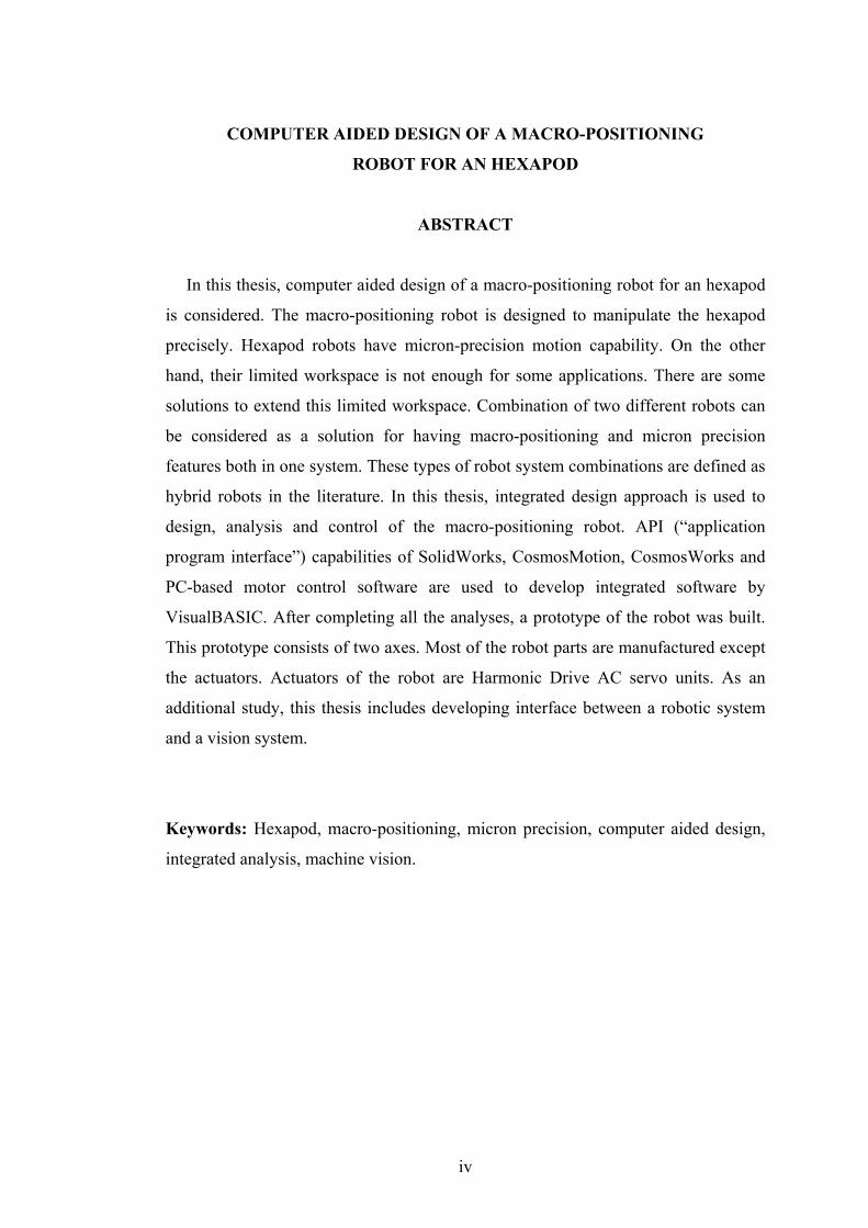
ABSTRACT
In this thesis, computer aided design of a macro-positioning robot for an hexapod
is considered. The macro-positioning robot is designed to manipulate the hexapod
precisely. Hexapod robots have micron-precision motion capability. On the other
hand, their limited workspace is not enough for some applications. There are some
solutions to extend this limited workspace. Combination of two different robots can
be considered as a solution for having macro-positioning and micron precision
features both in one system. These types of robot system combinations are defined as
hybrid robots in the literature. In this thesis, integrated design approach is used to
design, analysis and control of the macro-positioning robot. API (“application
program interface”) capabilities of SolidWorks, CosmosMotion, CosmosWorks and
PC-based motor control software are used to develop integrated software by
VisualBASIC. After completing all the analyses, a prototype of the robot was built.
This prototype consists of two axes. Most of the robot parts are manufactured except
the actuators. Actuators of the robot are Harmonic Drive AC servo units. As an
additional study, this thesis includes developing interface between a robotic system
and a vision system.
Keywords: Hexapod, macro-positioning, micron precision, computer aided design,
integrated analysis, machine vision.
iv
BİR HEGZAPOD İÇİN BİLGİSAYAR DESTEKLİ
MAKRO-KONUMLANDIRICI ROBOT TASARIMI
ÖZ
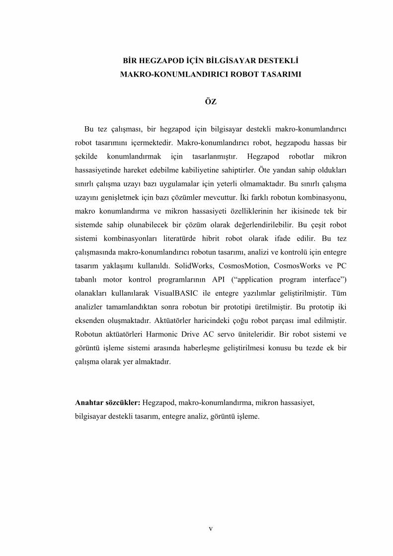
Bu tez çalışması, bir hegzapod için bilgisayar destekli makro-konumlandırıcı
robot tasarımını içermektedir. Makro-konumlandırıcı robot, hegzapodu hassas bir
şekilde konumlandırmak için tasarlanmıştır. Hegzapod robotlar mikron
hassasiyetinde hareket edebilme kabiliyetine sahiptirler. Öte yandan sahip oldukları
sınırlı çalışma uzayı bazı uygulamalar için yeterli olmamaktadır. Bu sınırlı çalışma
uzayını genişletmek için bazı çözümler mevcuttur. İki farklı robotun kombinasyonu,
makro konumlandırma ve mikron hassasiyeti özelliklerinin her ikisinede tek bir
sistemde sahip olunabilecek bir çözüm olarak değerlendirilebilir. Bu çeşit robot
sistemi kombinasyonları literatürde hibrit robot olarak ifade edilir. Bu tez
çalışmasında makro-konumlandırıcı robotun tasarımı, analizi ve kontrolü için entegre
tasarım yaklaşımı kullanıldı. SolidWorks, CosmosMotion, CosmosWorks ve PC
tabanlı motor kontrol programlarının API (“application program interface”)
olanakları kullanılarak VisualBASIC ile entegre yazılımlar geliştirilmiştir. Tüm
analizler tamamlandıktan sonra robotun bir prototipi üretilmiştir. Bu prototip iki
eksenden oluşmaktadır. Aktüatörler haricindeki çoğu robot parçası imal edilmiştir.
Robotun aktüatörleri Harmonic Drive AC servo üniteleridir. Bir robot sistemi ve
görüntü işleme sistemi arasında haberleşme geliştirilmesi konusu bu tezde ek bir
çalışma olarak yer almaktadır.
Anahtar sözcükler: Hegzapod, makro-konumlandırma, mikron hassasiyet,
bilgisayar destekli tasarım, entegre analiz, görüntü işleme.
v
CONTENTS
Page
THESIS EXAMINATION RESULT FORM .............................................................. ii
ACKNOWLEDGEMENTS ........................................................................................ iii
ABSTRACT................................................................................................................ iv
ÖZ ................................................................................................................................ v
CHAPTER ONE – INTRODUCTION .................................................................... 1
1.1 Hexapod Robot.................................................................................................. 4
1.2 Macro-positioning Manipulator ........................................................................ 5
1.2.1 Industrial Manipulators.............................................................................. 5
1.2.2 Special Manipulators ................................................................................. 6
CHAPTER TWO – ROBOTIC SYSTEMS............................................................. 7
2.1 Introduction ...................................................................................................... 7
2.2 Basics of Robotic Systems ................................................................................ 8
2.3 Classification of Robots .................................................................................... 9
2.3.1 Degrees of Freedom .................................................................................. 9
2.3.2 Workspace Geometry .............................................................................. 10
2.3.3 Motion Characteristic .............................................................................. 10
2.3.4 Drive Technology .................................................................................... 12
2.3.5 Kinematic Structure ................................................................................. 12
2.4 Mechanics of Robots ....................................................................................... 12
2.5 Robot Manipulators......................................................................................... 13
2.5.1 Serial Manipulators ................................................................................. 14
2.5.2 Parallel Manipulators............................................................................... 14
2.5.3 Hybrid Manipulators................................................................................ 16
vi
2.6 Control Systems .............................................................................................. 17
2.6.1 Controllers ............................................................................................... 17
2.6.2 Actuators.................................................................................................. 18
2.6.2.1 AC Servo Motors ............................................................................. 19
2.6.2.2 DC Servo Motors ............................................................................. 20
2.6.2.3 Stepper Motors................................................................................. 21
CHAPTER THREE – INTEGRATED DESIGN OF THE
MACRO-POSITIONING ROBOT ........................................................................ 23
3.1 Introduction ..................................................................................................... 23
3.2 Initial Design of the Macro-positioning Robot ............................................... 24
3.3 Selecting Appropriate Actuators ..................................................................... 24
3.4 Design of the First Model................................................................................ 28
3.4.1 Designing a Solid Model ......................................................................... 28
3.4.2 Analysing the Model ............................................................................... 30
3.5 Design of the Final Model............................................................................... 31
3.5.1 Designing a Solid Model ......................................................................... 32
3.5.2 Analysing the Model ............................................................................... 33
3.5.3 Design of a Console for the Robot .......................................................... 34
3.5.4 Analysing the Robot with the Console .................................................... 35
3.6 Modelling 3rd and 4th Axes of the Robot ......................................................... 36
3.7 Manufacturing of the Robot ............................................................................ 37
CHAPTER FOUR – CONTROLLING AND SIMULATION OF THE
MACRO-POSITIONING ROBOT ....................................................................... 41
4.1 Introduction ..................................................................................................... 41
4.2 Control System of the Robot ........................................................................... 41
4.3 Simulation and Control of the Robot .............................................................. 45
4.3.1 Developed VisualBASIC program for Controlling ................................. 45
4.3.2 Modelling of the Robot by a VisualBASIC Program.............................. 48
4.3.3 Simulation and Forward Kinematic Analyses ......................................... 48
4.4 Payload Test and Autotune of the Servo Units ............................................... 50
vii
CHAPTER FIVE – DEVELOPING INTERAFCE BETWEEN A SCARA
ROBOT AND VISION SYSTEM........................................................................... 53
5.1 Introduction ..................................................................................................... 53
5.2 System Descriptions ........................................................................................ 53
5.2.1 Scara Robot System................................................................................. 53
5.2.2 Industrial PC with the Programming Software........................................ 54
5.2.3 Vision System.......................................................................................... 55
5.2.4 Feeding System........................................................................................ 56
5.3 Serial Interface ................................................................................................ 57
5.3.1 Pin Assignment and Connection.............................................................. 57
5.3.2 Spreadsheet and Communication Protocol.............................................. 58
5.3.3 Program Modification.............................................................................. 59
5.4 Parallel Interface.............................................................................................. 59
5.4.1 Wiring Diagram....................................................................................... 60
5.4.2 Pin Assignment and Connection.............................................................. 61
5.4.3 Program Modification.............................................................................. 62
5.5 Test of Serial and Parallel Interface ................................................................ 63
CHAPTER SIX – CONCLUSIONS ....................................................................... 65
REFERENCES......................................................................................................... 67
APPENDIX A – 2D MANUFACTURING DRAWINGS OF THE
MACRO-POSITIONING ROBOT ........................................................................ 75
APPENDIX B – VISUALBASIC PROGRAM FOR CONTROLLING OF THE
MACRO-POSITIONING ROBOT ........................................................................ 83
APPENDIX C– VISUAL BASIC PROGRAM FOR MODELLING OF THE
MACRO-POSITIONING ROBOT ........................................................................ 88
viii

ix
APPENDIX D – VISUALBASIC PROGRAM FOR SIMULATION AND
FORWARD KINEMATIC ANALYSES OF THE MACRO-POSITIONING
ROBOT ..................................................................................................................... 93
APPENDIX E – INTERFACE PROGRAM AND COMMUNICATION
PROTOCOL OF THE SCARA ROBOT FOR VISION SYSTEM ................... 99
CHAPTER ONE
INTRODUCTION
Using of robotic systems in industrial applications is increasing through
developments in mechanic and electronic systems. To adapt a robotic system in an
application, the system should ensure the requirements of the application such as
precision, high speed, long life time, good repeatability, etc. The requirements
generally depend on application types. For example, while a medical application
requires precise movement, an industrial one can need just high speed.
Improvements in design and control technologies make it possible to manufacture a
robotic system to ensure most of these requirements. While parallel manipulators,
especially hexapod robots, are used for micro-positioning, serial manipulators are
generally used for macro positioning. On the other hand, hybrid manipulators, the
combination of a serial and parallel manipulator, have advantages of both types.
Therefore, a hybrid robotic system can be used in sophisticated applications such as
surgical operations. The first patent for a robot design was issued in the UK by
British inventor Cyril W. Kenward (1957). Burisch A. et al. (2005) worked on the
design of a parallel hybrid micro-scara robot for high precision assembly. One may
find general design rules for building rigid-robotic manipulators in the work of Yang
& Tzeng (1986), Asada (1987), Toumi & Asada (1987), and Park & Cho (1991).
Designing, controlling and manufacturing of a mechatronic system and more
specifically a robotic system are complex issues. In the literature, there are several
design methods for mechatronic systems. One of them is parametric modeling.
Parametric modeling has two approaches as algebraic approach and AI (Artificial
Intelligence) approach (Verroust, Schonek & Roller, 1992). Configuration design is
another integrated design method. It is used to define relationship between parts to
satisfy the constraints and the product specification (Koo, Han & Lee, 1998).
Configuration design starts from a set of parts in the initial design stage. One may
find detailed information about the configuration design in the work of Brown
(1999), Franke (1998), Kang & Han (1997), Sabin & Weigel (1998), Yu (1996) and
1
2
Koo et al (1998). Researches of Bok, Myung & Han (2000) and Mcalinden et al.
(1998) in the engineering design area apply knowledge-based system and AI
methods also. The implemented design expert system which is developed by Myung
& Han consists of a commercial expert system shell, a commercial CAD system, and
an API (Application Programming Interface) which integrates the entire system
(Myung & Han, 2001).
Controlling of servo motors is important issue for many researchers. Dulger,
Kirecci, & Topalbekiroglu (2001) modelled and simulated servo motors by using
their mechanical and electrical properties. Asynchronous and synchronous motors
with hybrid controllers which were adjusted by proportional-integral (PI) controllers
via neural networks investigated by Dandil, Gokbulut, & Ata (2004) and Lin & Wai
(1998). Various types of control methods are used to control servo motors such as
H∞ robust control (Ximei & Qingding, 2005), adaptive fuzzy sliding-mode (Lin &
Chiu, 1998), variable structure approach (Hashimoto, Yamamoto, Yanagisawa, &
Harashima, 1988), micro-processor based robust control (Tzou & Wu, 1990) and
learning approach (Han, Kim, Ha, Lee, & Park, 1995). Different servo motor drivers
comparisons can be found in the study of Yamamoto & Shinohara (1996). A real-
time zone-adaptive control model for a scara type robot arm is developed by Coyle-
Byrne & Klafter (1990).
In this thesis, computer aided design of a macro-positioning robot for a hexapod is
comprised. The purpose of this design is macro-positioning of a parallel manipulator
namely hexapod. The hexapod is designed and manufactured for micro-positioning
with micron-precision. One of the disadvantages of hexapod robot is its limited
workspace. In some applications such as surgical operations, robots are required to
have precise movements and also not very limited workpace. To extend the
workspace of the hexapod, macro-positioning of it by another robot system could be
considered as a solution. While the macro positioning robot is designed, integrated
design method is used. This method has more advantages than most of the other
methods for designing of a robotic system. First of all, this method makes possible to
design a system within very limited time. Computer aided design consists of
3
computer solutions of mathematical models for solid modeling, assembly, motion
and force, and finite element analyses. Control system and control software of robots
are developed according to the results of these analyses. Integrated design approach
is also used for controlling of the robot. Integrated software has been developed by
VisualBASIC using the API (“application program interface”) capabilities of
Solidworks, CosmosMotion, CosmosWorks, and PC-based motor control software.
Solid modelling and 2D manufacturing drawings of the system are accomplished
by SolidWorks (SolidWorks Corp., 2007) solid modelling program. FEM Analyses
are done with CosmosWorks (SolidWorks Corp., 2007) analysis program. Kinetic
and Kinematic simulations are performed with CosmosMotion (SolidWorks Corp.,
2007) simulation program. To locate and assembly the parts of the model, to perform
inverse and forward kinematic simulations, integrated design programs are written by
Visual BASIC (MSDN, 2006) programming language with using API codes. Visual
BASIC is also used to write a program for controlling of the system. Control system
which consists of a control panel and a control program are designed and produced
for controlling of the robot. Actuators of the robot are brushless AC servo motors.
These actuators are controlled by a PC system. Point-to-point control is applied to
servo motors, so to the robot. Prototype of the robot is manufactured.
Popularity of machine vision technology for mechatronic systems is increasing
also. This technology provides benefits for controlling of a mechatronic system. One
of the earliest surveys of image processing is done by Huang, Schreiber, & Tretiak
(1971). It is presented by the influential paper of Barrow & Tenenbaum (1978) that
machine vision is concerned with the process of recovering information about the
surfaces imaged. There are more researches about machine vision which are done by
Marr & Ullman (1981), Barrow & Tenenbaum (1981) and Poggio & Koch (1985).
Nishihara & Poggio (1984) deal with the application of machine vision to robots.
The automation of visual inspection is surveyed by Chin & Harlow (1982).
Additionally this thesis includes a chapter (Chapter 5) about developing interface
between a robotic system and vision system. The aim of this development is to
4
provide simultaneous work of both systems. To develop the interface, parallel and
serial connections are used. In addition, programs of the robot and the vision system
are modified.
This thesis is a part of a research project (TÜBİTAK, Project number: 104M373).
Some sections of the thesis are created by taking consideration of the project report
of Karagülle, H., Sarıgül, S., Kıral, Z., Malgaca, L, & Akdag, M. (01 July 2007).
1.1 Hexapod Robot
A hexapod is a kind of parallel manipulator using an octahedral assembly of
struts. It has six degrees of freedom (x, y, z, pitch, roll, & yaw). Stewart – Gough
platform is another name of the Hexapod, because first parallel manipulators with 6
DOF came into existence as a result of the works of Gough & Whitehall (1962) and
Stewart (1965). They are used in machine tool technology, crane technology,
underwater research, air-to-sea rescue, flight simulation, satellite dish positioning,
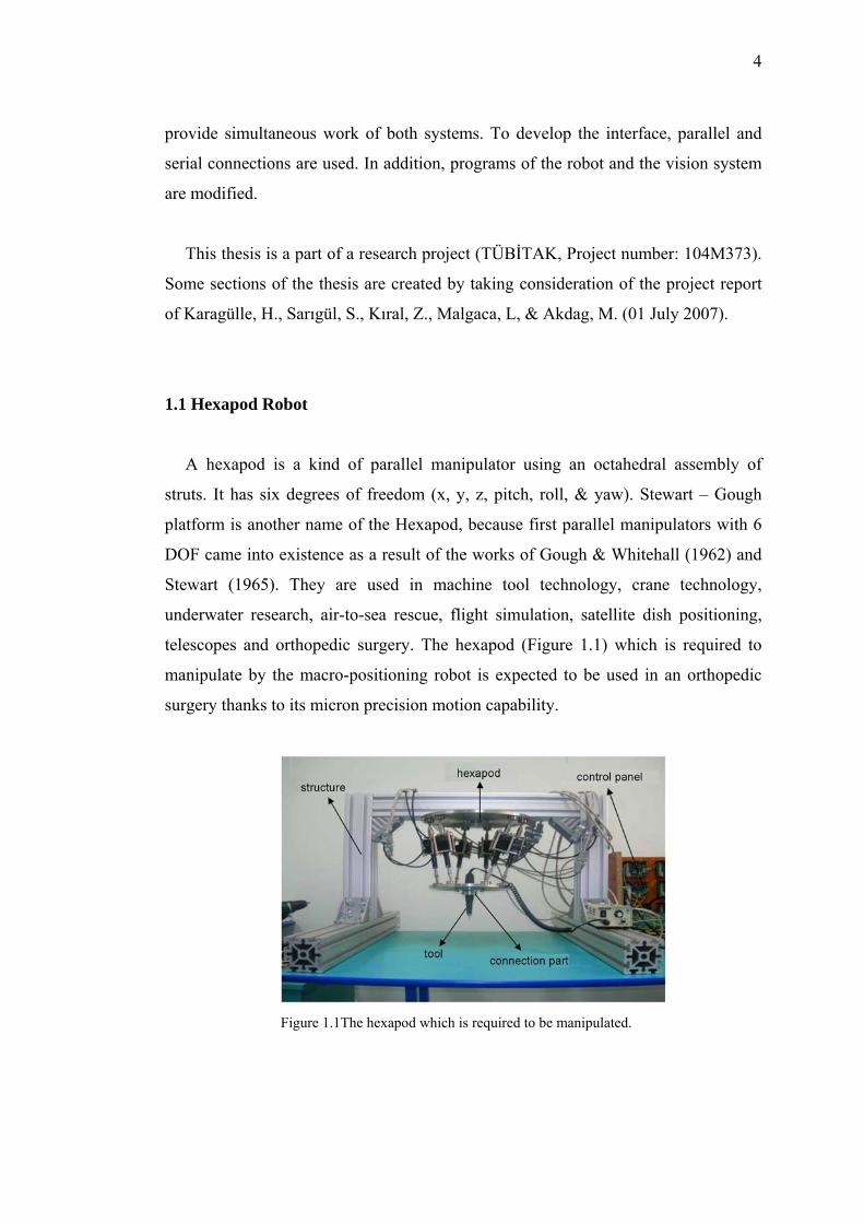
telescopes and orthopedic surgery. The hexapod (Figure 1.1) which is required to
manipulate by the macro-positioning robot is expected to be used in an orthopedic
surgery thanks to its micron precision motion capability.
Figure 1.1The hexapod which is required to be manipulated.
5
1.2 Macro-positioning Manipulator
Once it was decided to manipulate the hexapod by a macro-positioning
manipulator, the alternatives were examined. There are many different types of
macro-positioning manipulators. Some of them have more standard features and they
are used in industrial applications. On the other hand, some kinds of manipulators are
designed just for a specific application. In this thesis, for the purpose of macro-
positioning of the hexapod, a special manipulator design is preferred instead of a
standard industrial manipulator.
1.2.1 Industrial Manipulators
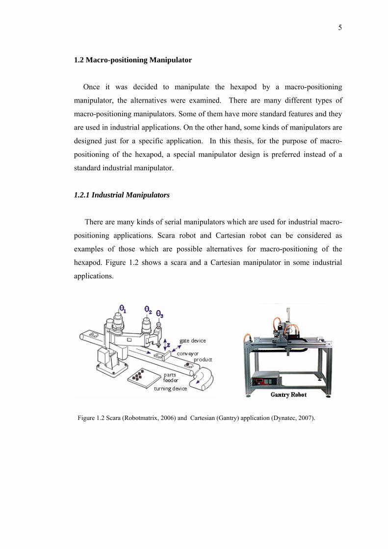
There are many kinds of serial manipulators which are used for industrial macro-
positioning applications. Scara robot and Cartesian robot can be considered as
examples of those which are possible alternatives for macro-positioning of the
hexapod. Figure 1.2 shows a scara and a Cartesian manipulator in some industrial
applications.
Figure 1.2 Scara (Robotmatrix, 2006) and Cartesian (Gantry) application (Dynatec, 2007).
6
1.2.2 Special Manipulators
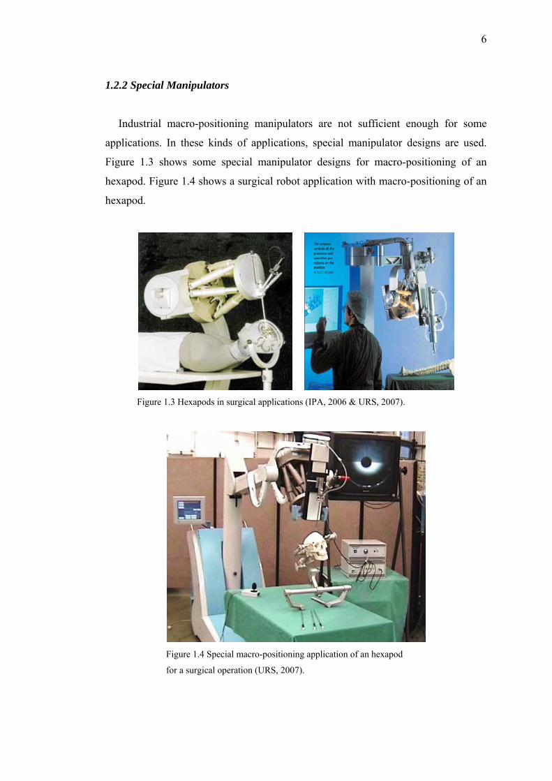
Industrial macro-positioning manipulators are not sufficient enough for some
applications. In these kinds of applications, special manipulator designs are used.
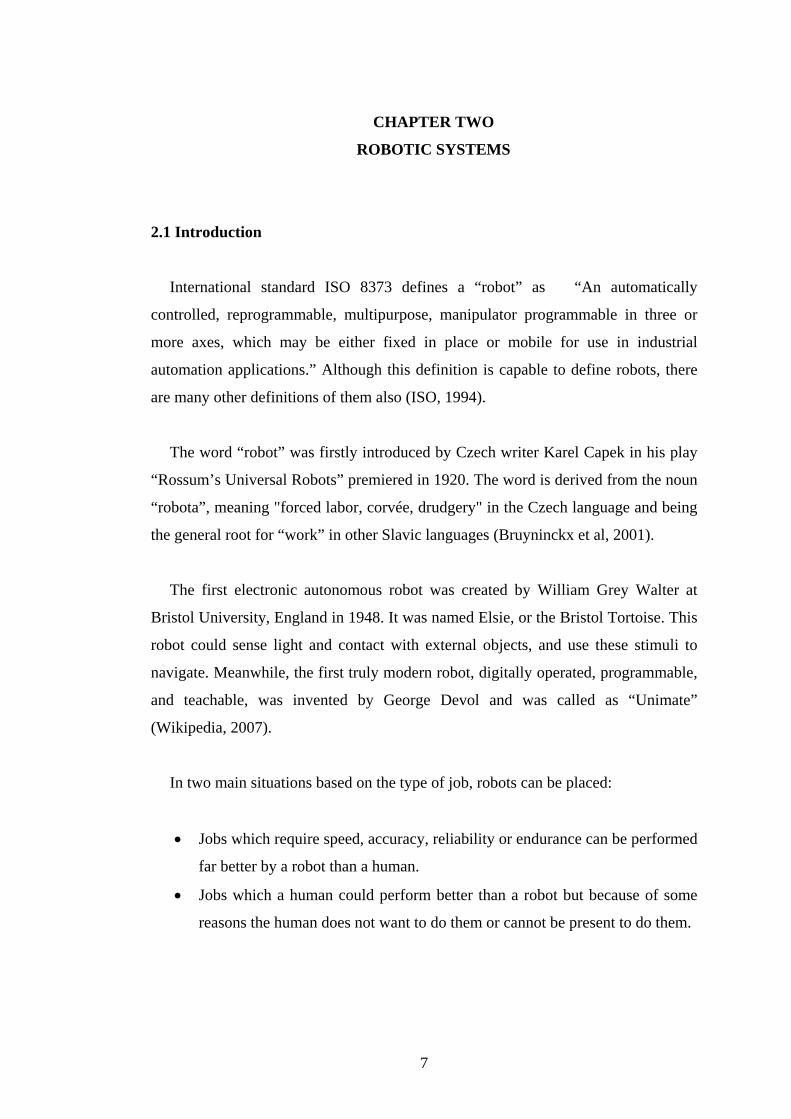
Figure 1.3 shows some special manipulator designs for macro-positioning of an
hexapod. Figure 1.4 shows a surgical robot application with macro-positioning of an
hexapod.
Figure 1.3 Hexapods in surgical applications (IPA, 2006 & URS, 2007).
Figure 1.4 Special macro-positioning application of an hexapod
for a surgical operation (URS, 2007).
CHAPTER TWO
ROBOTIC SYSTEMS
2.1 Introduction
International standard ISO 8373 defines a “robot” as “An automatically
controlled, reprogrammable, multipurpose, manipulator programmable in three or
more axes, which may be either fixed in place or mobile for use in industrial
automation applications.” Although this definition is capable to define robots, there
are many other definitions of them also (ISO, 1994).
The word “robot” was firstly introduced by Czech writer Karel Capek in his play
“Rossum’s Universal Robots” premiered in 1920. The word is derived from the noun
“robota”, meaning "forced labor, corvée, drudgery" in the Czech language and being
the general root for “work” in other Slavic languages (Bruyninckx et al, 2001).
The first electronic autonomous robot was created by William Grey Walter at
Bristol University, England in 1948. It was named Elsie, or the Bristol Tortoise. This
robot could sense light and contact with external objects, and use these stimuli to
navigate. Meanwhile, the first truly modern robot, digitally operated, programmable,
and teachable, was invented by George Devol and was called as “Unimate”
(Wikipedia, 2007).
In two main situations based on the type of job, robots can be placed:
• Jobs which require speed, accuracy, reliability or endurance can be performed
far better by a robot than a human.
• Jobs which a human could perform better than a robot but because of some
reasons the human does not want to do them or cannot be present to do them.
7
8
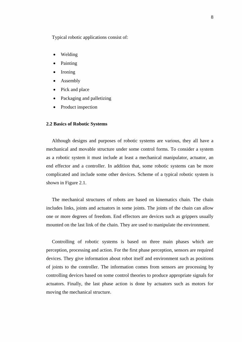
Typical robotic applications consist of:
• Welding
• Painting
• Ironing
• Assembly
• Pick and place
• Packaging and palletizing
• Product inspection
2.2 Basics of Robotic Systems
Although designs and purposes of robotic systems are various, they all have a
mechanical and movable structure under some control forms. To consider a system
as a robotic system it must include at least a mechanical manipulator, actuator, an
end effector and a controller. In addition that, some robotic systems can be more
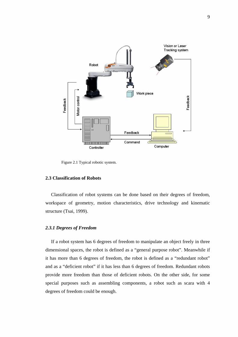
complicated and include some other devices. Scheme of a typical robotic system is
shown in Figure 2.1.
The mechanical structures of robots are based on kinematics chain. The chain
includes links, joints and actuators in some joints. The joints of the chain can allow
one or more degrees of freedom. End effectors are devices such as grippers usually
mounted on the last link of the chain. They are used to manipulate the environment.
Controlling of robotic systems is based on three main phases which are
perception, processing and action. For the first phase perception, sensors are required
devices. They give information about robot itself and environment such as positions
of joints to the controller. The information comes from sensors are processing by
controlling devices based on some control theories to produce appropriate signals for
actuators. Finally, the last phase action is done by actuators such as motors for
moving the mechanical structure.
9
Figure 2.1 Typical robotic system.
2.3 Classification of Robots
Classification of robot systems can be done based on their degrees of freedom,
workspace of geometry, motion characteristics, drive technology and kinematic
structure (Tsai, 1999).
2.3.1 Degrees of Freedom
If a robot system has 6 degrees of freedom to manipulate an object freely in three
dimensional spaces, the robot is defined as a “general purpose robot”. Meanwhile if
it has more than 6 degrees of freedom, the robot is defined as a “redundant robot”
and as a “deficient robot” if it has less than 6 degrees of freedom. Redundant robots
provide more freedom than those of deficient robots. On the other side, for some
special purposes such as assembling components, a robot such as scara with 4
degrees of freedom could be enough.
10
2.3.2 Workspace Geometry
The volume of space which end effectors can reach represents the workspace of a
manipulator. If the end effector reaches every point within the volume of space at
least one orientation, this workspace is called as “reachable workspace”. If the end
effector reaches every point within the volume of space in all possible orientations,
this workspace is called as “dextrous workspace”.
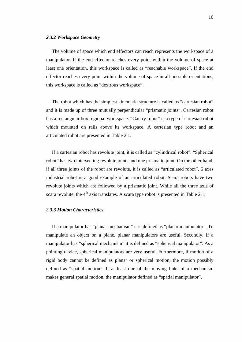
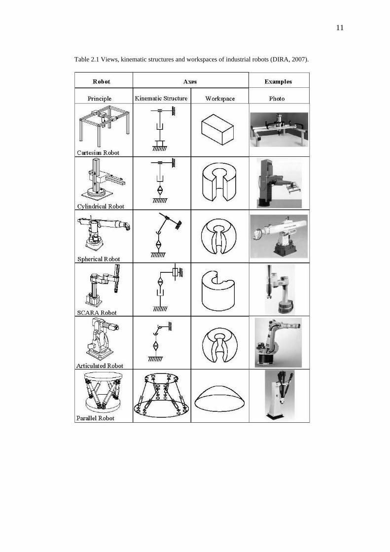
The robot which has the simplest kinematic structure is called as “cartesian robot”
and it is made up of three mutually perpendicular “prismatic joints”. Cartesian robot
has a rectangular box regional workspace. “Gantry robot” is a type of cartesian robot
which mounted on rails above its workspace. A cartesian type robot and an
articulated robot are presented in Table 2.1.
If a cartesian robot has revolute joint, it is called as “cylindrical robot”. “Spherical
robot” has two intersecting revolute joints and one prismatic joint. On the other hand,
if all three joints of the robot are revolute, it is called as “articulated robot”. 6 axes
industrial robot is a good example of an articulated robot. Scara robots have two
revolute joints which are followed by a prismatic joint. While all the three axis of
scara revolute, the 4th axis translates. A scara type robot is presented in Table 2.1.
2.3.3 Motion Characteristics
If a manipulator has “planar mechanism” it is defined as “planar manipulator”. To
manipulate an object on a plane, planar manipulators are useful. Secondly, if a
manipulator has “spherical mechanism” it is defined as “spherical manipulator”. As a
pointing device, spherical manipulators are very useful. Furthermore, if motion of a
rigid body cannot be defined as planar or spherical motion, the motion possibly
defined as “spatial motion”. If at least one of the moving links of a mechanism
makes general spatial motion, the manipulator defined as “spatial manipulator”.
11
Table 2.1 Views, kinematic structures and workspaces of industrial robots (DIRA, 2007).
12
2.3.4 Drive Technology
Although there are three main drive technologies such as electric, hydraulic and
pneumatic, most of the manipulators use electric servo motors or stepper motors due
to the fact that the advantages of electric motors are more obvious. From the other
point of view, hydraulic and pneumatic drive has some advantages such as high-load-
carrying capabilities.
2.3.5 Kinematic Structure
The robots are also classified by their kinematic structures. If a robot has open-
loop chain kinematic structure, it is defined as “serial robot” or “open loop
manipulator”. If it has closed loop-chain kinematic structure, it is defined as “parallel
manipulator”. Moreover, if a robot system consists of both structure types it is called
as “hybrid manipulator”.
2.4 Mechanics of Robots
Robotics is the science or study which consists of manipulator design, basic
mechanics, trajectory planning and control, programming and machine intelligence
and so on. As a science branch mechanics involves interrelated subjects such as
kinematics, statics and dynamics.
“Kinematic analysis” and “kinematic synthesis” are two different approaches of
robot kinematics. The derivation of relative motions among various links of a
manipulator is the working area of kinematic analysis. Kinematic analysis problems
are divided into two main groups as “forward kinematics” and “inverse kinematics”.
Inverse kinematics is the process for determining the parameters of an actuated joint
of a robot manipulator in order to achieve a desired pose. Inverse kinematics finds
the joint angles given the desired configuration of the Figure (i.e., end effector). In
the general case there is no analytic solution for the inverse kinematics problem.
13
However, inverse kinematics may be solved via nonlinear programming techniques.
On the other hand, forward kinematics is the process of relating a system's pose to
the position and orientation of the end effector. Forward kinematics can be
considered as the inverse of inverse kinematics. It is called also as “direct
kinematics”. Kinematic synthesis is the reverse process of kinematic analysis. In
kinematic synthesis a new machine or manipulator is devised to possess certain
desired kinematic properties.
The forces which act on a robot manipulator vary such as gravity forces, applied
load forces, inertia forces, friction forces. To size the parts of the manipulator
properly “Statics” deals with those forces. The forces of equilibrium depend on the
configuration of a robot manipulator.
Dynamical analysis and dynamical synthesis deal with the dynamics of robot
manipulators. In a similar way of kinematic analysis, dynamical analysis is divided
into two main groups as direct dynamics and inverse dynamics. The resulting motion
of the end effector is calculated by giving a set of actuated joint torque and force
functions. This method is called as direct dynamics. Contrary to direct dynamics, in
inverse dynamics method, actuated joint torque and/or force functions are found by
giving a trajectory of the end effector as a function of time. Dynamical synthesis is
much more complicated than dynamical analysis and it is reverse of dynamical
analysis (Tsai, 1999).
2.5 Robot Manipulators
According to B.Z. Sandler a robot manipulator is "a mechanism, usually
consisting of a series of segments, jointed or sliding relative to one another, for the
purpose of grasping and moving objects usually in several degrees of freedom.” It
may be remotely controlled by a computer or by a human. There are three main types
of robot manipulators. Those are serial, parallel and hybrid manipulators.
14
2.5.1 Serial Manipulators
Serial manipulators which consist of a serial chain of rigid links connected by
joints are most common industrial robots. Their joints are generally revolute joint.
Most serial manipulators have a anthropomorphic arm structure. This means that
they have “shoulder” (first two joints), an “elbow” (third joint) and a “wrist” (last
three joints). According to rigid body motion, to place a manipulated object in an
arbitrary position and orientation in the workspace of the robot a robot must have at
least six degrees of freedom. Therefore most of the serial robots have six joints. On
the other hand, scara robot which is one of the most common serial robot
applications has only four degrees of freedom. It is a special assembly robot and used
in generally pick and place applications. Figure 2.2 shows a serial robot example
(scara).
Advantages of serial manipulators:
• Larger dextrous workspace,
• Simplicity of the forward and inverse position and velocity kinematics,
• Able to achieve high velocities and accelerations,
• Have revolute joints which are cheaper rather than prismatic joints.
Disadvantages of serial manipulators:
• They are very heavy because the links must be stiff,
• Errors are accumulated and amplified from link to link,
• Not energy efficient.
2.5.2 Parallel Manipulators
Parallel manipulator which consists of a fixed (base) and a movable (end effector)
platform is a closed chain mechanism. Base platform is connected to the end effector
platform by a number of “legs”. These legs are connected to the platforms by
15
spherical or universal joints. Each leg is controlled by an actuator. The degree of
freedom depends on number of actuated legs. Most important advantages of the
parallel manipulators are accurate position capabilities and light constructions
because the links feel only traction or compression, not bending. In addition that,
actuators can be placed in the base platform, hence weight of movable construction
decreases (Bruyninckx et al, 2001).
Advantages of parallel manipulators:
• High structural stiffness and load capacity.
• High bandwidth motion capability
Disadvantages of parallel manipulators:
• Limited workspace
• Loosing stiffness in singular position completely
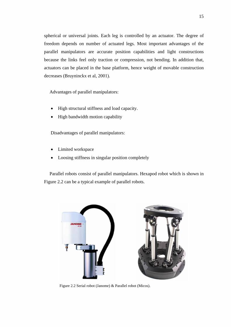
Parallel robots consist of parallel manipulators. Hexapod robot which is shown in
Figure 2.2 can be a typical example of parallel robots.
Figure 2.2 Serial robot (Janome) & Parallel robot (Micos).
16
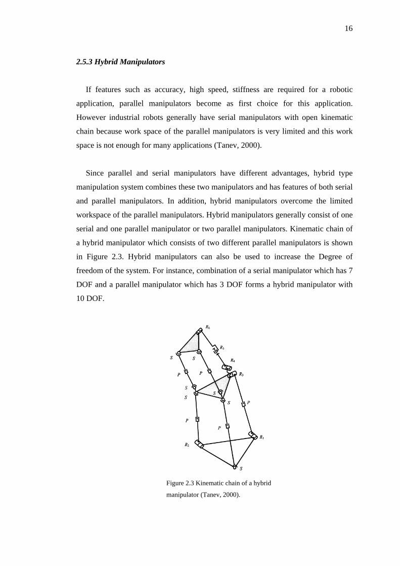
2.5.3 Hybrid Manipulators
If features such as accuracy, high speed, stiffness are required for a robotic
application, parallel manipulators become as first choice for this application.
However industrial robots generally have serial manipulators with open kinematic
chain because work space of the parallel manipulators is very limited and this work
space is not enough for many applications (Tanev, 2000).
Since parallel and serial manipulators have different advantages, hybrid type
manipulation system combines these two manipulators and has features of both serial
and parallel manipulators. In addition, hybrid manipulators overcome the limited
workspace of the parallel manipulators. Hybrid manipulators generally consist of one
serial and one parallel manipulator or two parallel manipulators. Kinematic chain of
a hybrid manipulator which consists of two different parallel manipulators is shown
in Figure 2.3. Hybrid manipulators can also be used to increase the Degree of
freedom of the system. For instance, combination of a serial manipulator which has 7
DOF and a parallel manipulator which has 3 DOF forms a hybrid manipulator with
10 DOF.
Figure 2.3 Kinematic chain of a hybrid
manipulator (Tanev, 2000).
17
2.6 Control Systems
Control systems are single devices, or a collection of devices that manage the
behavior of other devices. Some devices are not controllable. Control system is an
interconnection of components connected or related in such a manner as to
command, direct, or regulate itself or another system. Control system of a robot
generally consists of controllers and actuators.
2.6.1 Controllers
There are three main types of controllers to control a motor. Those are standalone,
PC based and hybrid systems. While a PC based controller requires a PC to run
system all the time, standalone controller doesn’t need a PC. However, standalone
controller needs a PC for programming it. Hybrid systems are combination of PC
based and standalone units. Table 2.2 compares these three systems and shows the
advantages and disadvantages of each one (Custom Solutions Inc., 2006). In this
thesis, a PC based controller is used to run motors via RS 232 cables.
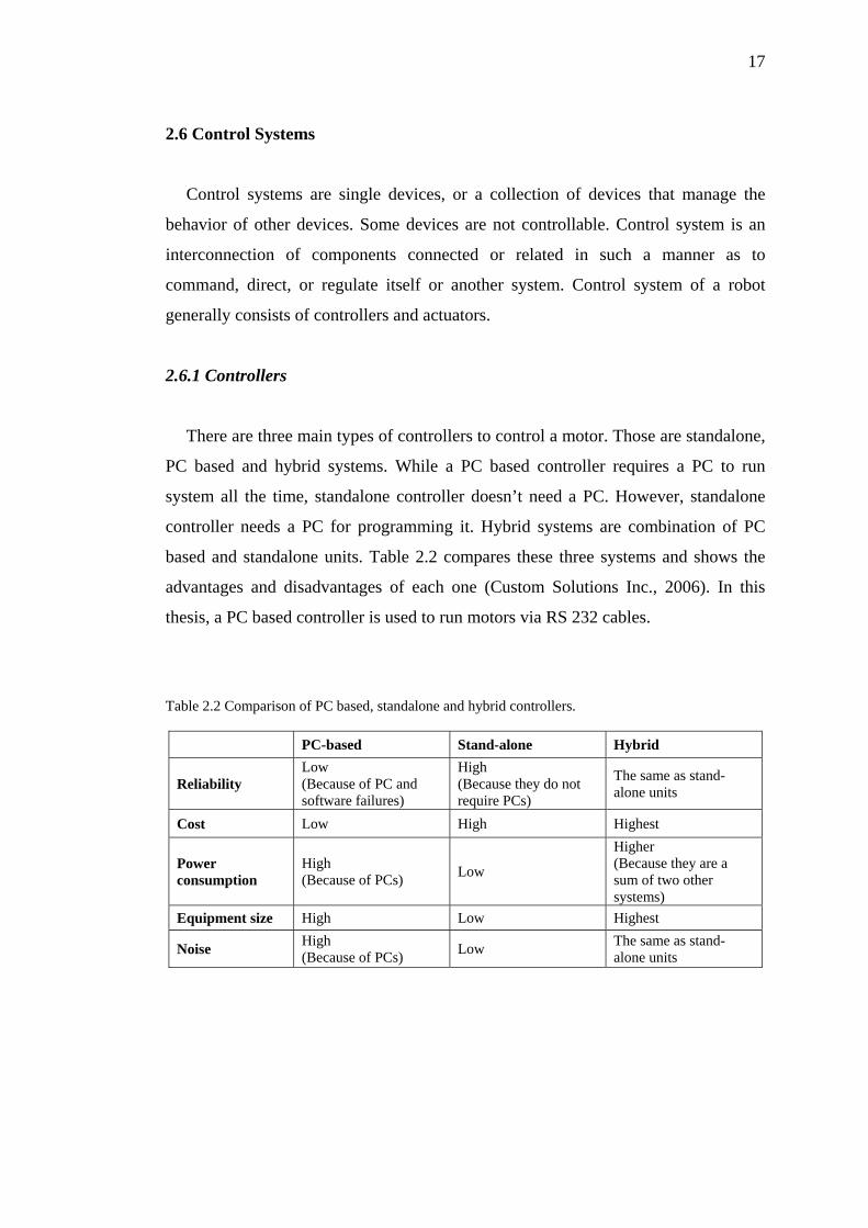
Table 2.2 Comparison of PC based, standalone and hybrid controllers.
PC-based Stand-alone Hybrid
Reliability Low (Because of PC and software failures)
High (Because they do not require PCs)
The same as stand-alone units
Cost Low High Highest
Power consumption
High (Because of PCs) Low
Higher (Because they are a sum of two other systems)
Equipment size High Low Highest
Noise High (Because of PCs) Low The same as stand-
alone units
18
2.6.2 Actuators
Actuators are mechanical devices for moving or controlling a mechanism or a
system. Actuators are frequently used mechanisms to introduce motion, or to clamp
an object so as to prevent motion. There are many different types of actuators such as
electrical motors, pneumatic actuators, hydraulic pistons, relays, comb drive,
piezoelectric actuators, and thermal bimorphs. In robotic applications, most
frequently used actuators are electrical motors. Electrical motors are divided into two
main categories depends on their working principles. Those are servo motors and
stepper motors.
In closed loop systems, most frequently used actuators are servo motors. Servo
motors usually come with a digital motor controller. The motor controller sends
velocity command signals to the amplifier which drives the servo motor. The servo
motor's position and velocity feedback are provided by an integral feedback device
(resolver) or devices (encoder and tachometer). These devices either connected
within the servo motor or are remotely mounted, often on the load itself. The
controller needs position and velocity feedback to compare them to the programmed
motion profile which is a set of programmed instructions and to adjust velocity. The
operation of servo motor is defined by the controller (in terms of time, position and
velocity).
Advantages of servo motors (Baldor Co., 2007):
• High performance,
• High speeds available with specialized controls,
• Wide variety of components,
• Small size.
19
Disadvantages of servo motors:
• High performances of servo motors are limited by controls and controllers,
• High speed torque of servo motors are limited by commutator or electronics,
• Higher costs compared to step motors.
Servo motors are divided into two main types as AC servo motors and DC servo
motors. In this thesis, AC servo motors are used as actuators of the system.
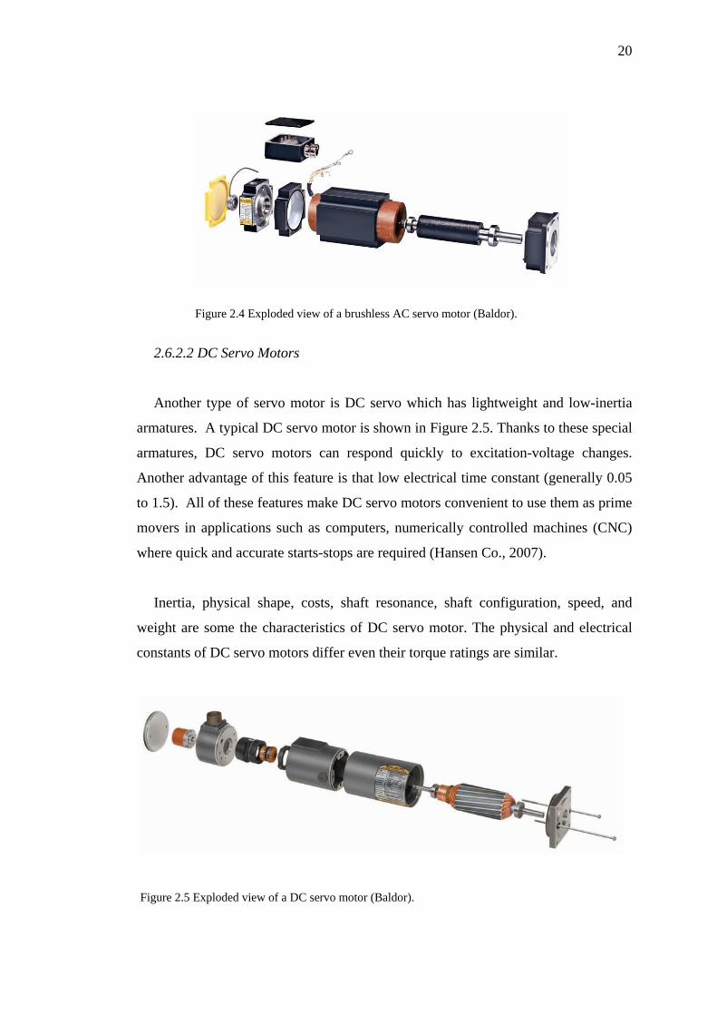
2.6.2.1 AC Servo Motors
AC servo motors have small-diameter which provides low inertia for fast starts,
stops, reversals and high-resistance rotors which provides an almost linear speed-
torque relationship for accurate control. Thanks to these features AC servo motors
obtain rapid, accurate response characteristics and they are used in AC servo
mechanisms and computers which require rapid and accurate response. Figure 2.4
shows a brushless type AC servo motor (Baldor Co., 2007).
AC servo motors have two windings. These windings are defined as fixed (or
reference) winding which is excited from a fixed voltage source and control winding
which is excited by an adjustable or variable control voltage. To balance power
inputs at maximum fixed-phase excitation and at maximum control-phase signal,
these windings generally have the same voltage-turns ratio.
Ideally torque of AC servo motors should be increased proportional to the control-
winding voltage. However, in real situations, this proportional relation doesn’t occur
but at zero speed. Because, under light load conditions, induction motors are unable
to respond to voltage input changes. So that, in real conditions, the respond of a
servo motor differs from that in ideal conditions.
20
Figure 2.4 Exploded view of a brushless AC servo motor (Baldor).
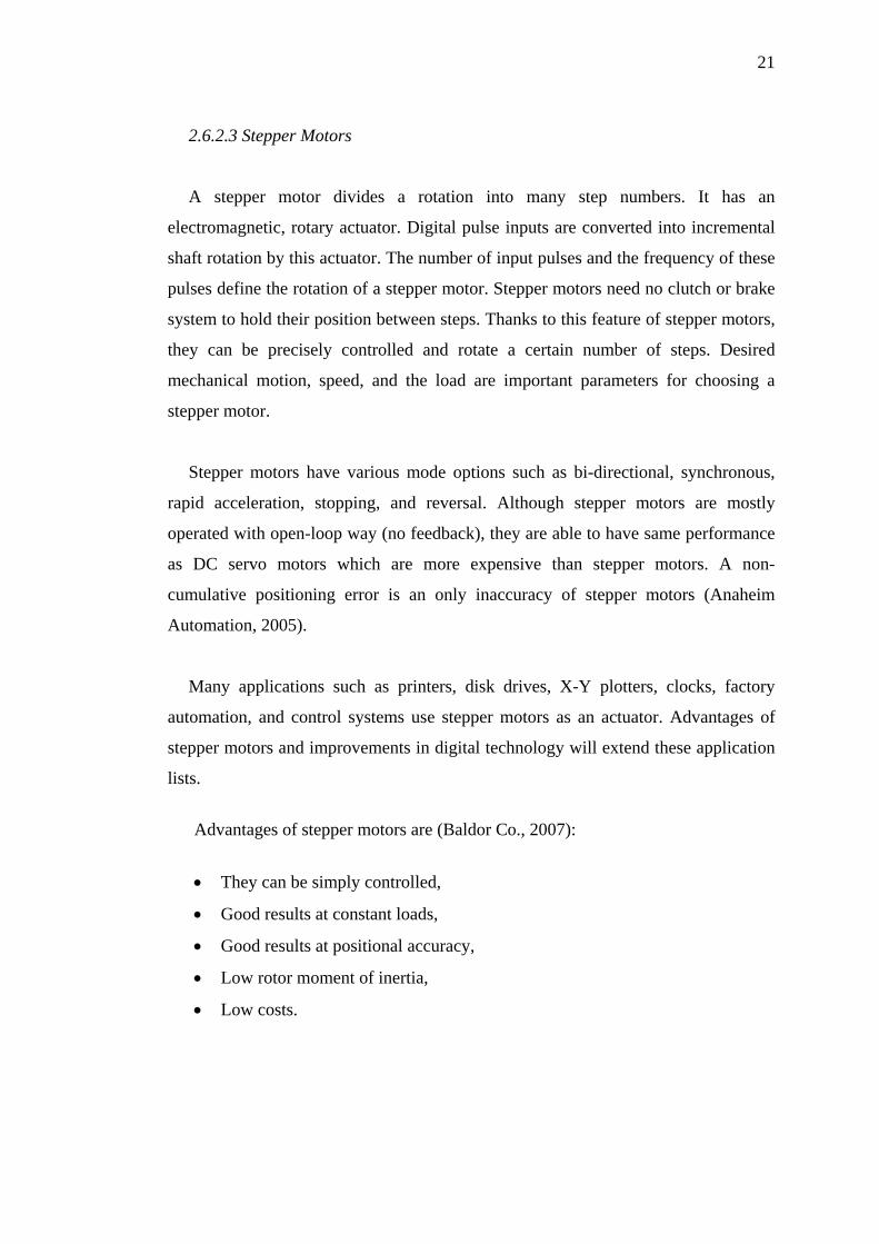
2.6.2.2 DC Servo Motors
Another type of servo motor is DC servo which has lightweight and low-inertia
armatures. A typical DC servo motor is shown in Figure 2.5. Thanks to these special
armatures, DC servo motors can respond quickly to excitation-voltage changes.
Another advantage of this feature is that low electrical time constant (generally 0.05
to 1.5). All of these features make DC servo motors convenient to use them as prime
movers in applications such as computers, numerically controlled machines (CNC)
where quick and accurate starts-stops are required (Hansen Co., 2007).
Inertia, physical shape, costs, shaft resonance, shaft configuration, speed, and
weight are some the characteristics of DC servo motor. The physical and electrical
constants of DC servo motors differ even their torque ratings are similar.
Figure 2.5 Exploded view of a DC servo motor (Baldor).
21
2.6.2.3 Stepper Motors
A stepper motor divides a rotation into many step numbers. It has an
electromagnetic, rotary actuator. Digital pulse inputs are converted into incremental
shaft rotation by this actuator. The number of input pulses and the frequency of these
pulses define the rotation of a stepper motor. Stepper motors need no clutch or brake
system to hold their position between steps. Thanks to this feature of stepper motors,
they can be precisely controlled and rotate a certain number of steps. Desired
mechanical motion, speed, and the load are important parameters for choosing a
stepper motor.
Stepper motors have various mode options such as bi-directional, synchronous,
rapid acceleration, stopping, and reversal. Although stepper motors are mostly
operated with open-loop way (no feedback), they are able to have same performance
as DC servo motors which are more expensive than stepper motors. A non-
cumulative positioning error is an only inaccuracy of stepper motors (Anaheim
Automation, 2005).
Many applications such as printers, disk drives, X-Y plotters, clocks, factory
automation, and control systems use stepper motors as an actuator. Advantages of
stepper motors and improvements in digital technology will extend these application
lists.
Advantages of stepper motors are (Baldor Co., 2007):
• They can be simply controlled,
• Good results at constant loads,
• Good results at positional accuracy,
• Low rotor moment of inertia,
• Low costs.
22
Disadvantages of stepper motors are (Baldor Co., 2007):
• Possibility to lose steps,
• Not good at varying loads,
• Energy inefficiency,
• Resonance problems.
CHAPTER THREE
INTEGRATED DESIGN OF
THE MACRO-POSITIONING ROBOT
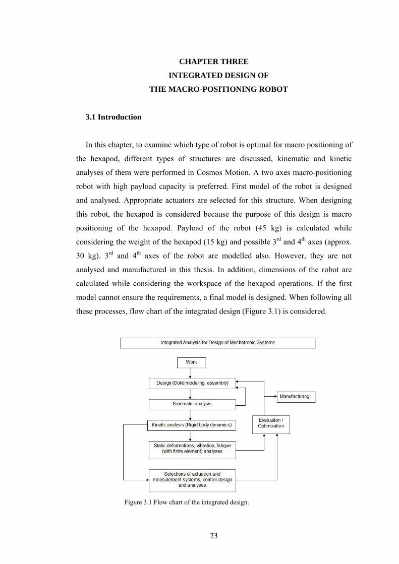
3.1 Introduction
In this chapter, to examine which type of robot is optimal for macro positioning of
the hexapod, different types of structures are discussed, kinematic and kinetic
analyses of them were performed in Cosmos Motion. A two axes macro-positioning
robot with high payload capacity is preferred. First model of the robot is designed
and analysed. Appropriate actuators are selected for this structure. When designing
this robot, the hexapod is considered because the purpose of this design is macro
positioning of the hexapod. Payload of the robot (45 kg) is calculated while
considering the weight of the hexapod (15 kg) and possible 3rd and 4th axes (approx.
30 kg). 3rd and 4th axes of the robot are modelled also. However, they are not
analysed and manufactured in this thesis. In addition, dimensions of the robot are
calculated while considering the workspace of the hexapod operations. If the first
model cannot ensure the requirements, a final model is designed. When following all
these processes, flow chart of the integrated design (Figure 3.1) is considered.
Figure 3.1 Flow chart of the integrated design.
23
24
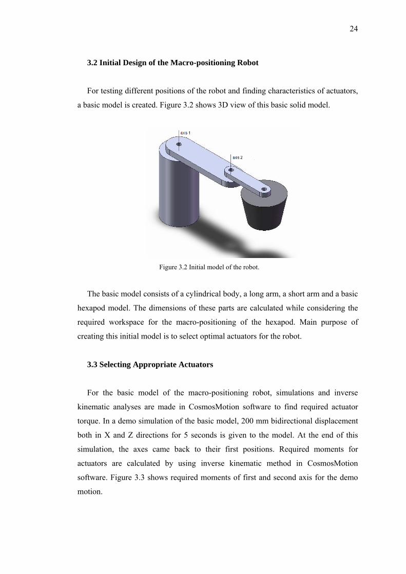
3.2 Initial Design of the Macro-positioning Robot
For testing different positions of the robot and finding characteristics of actuators,
a basic model is created. Figure 3.2 shows 3D view of this basic solid model.
Figure 3.2 Initial model of the robot.
The basic model consists of a cylindrical body, a long arm, a short arm and a basic
hexapod model. The dimensions of these parts are calculated while considering the
required workspace for the macro-positioning of the hexapod. Main purpose of
creating this initial model is to select optimal actuators for the robot.
3.3 Selecting Appropriate Actuators
For the basic model of the macro-positioning robot, simulations and inverse
kinematic analyses are made in CosmosMotion software to find required actuator
torque. In a demo simulation of the basic model, 200 mm bidirectional displacement
both in X and Z directions for 5 seconds is given to the model. At the end of this
simulation, the axes came back to their first positions. Required moments for
actuators are calculated by using inverse kinematic method in CosmosMotion
software. Figure 3.3 shows required moments of first and second axis for the demo
motion.
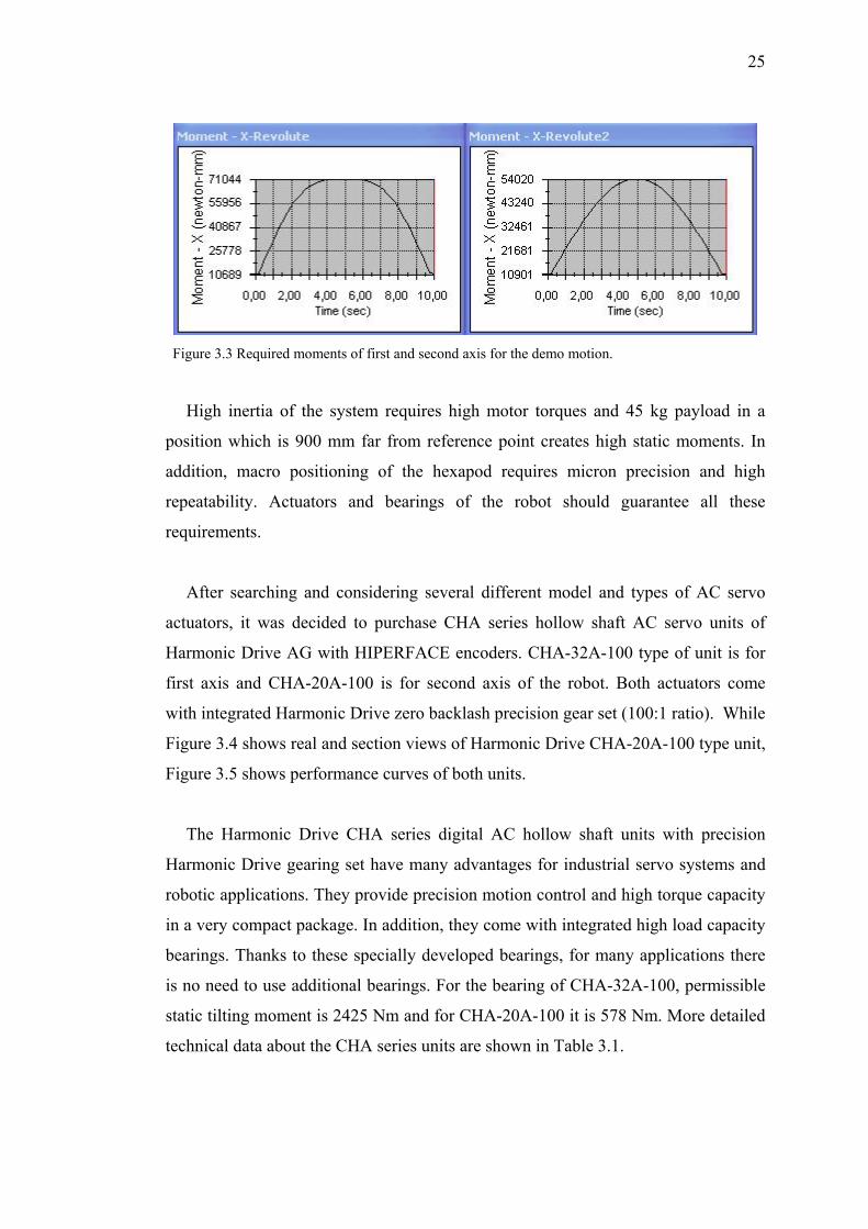
25
Figure 3.3 Required moments of first and second axis for the demo motion.
High inertia of the system requires high motor torques and 45 kg payload in a
position which is 900 mm far from reference point creates high static moments. In
addition, macro positioning of the hexapod requires micron precision and high
repeatability. Actuators and bearings of the robot should guarantee all these
requirements.
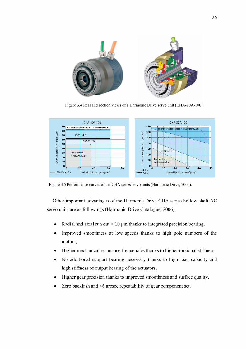
After searching and considering several different model and types of AC servo
actuators, it was decided to purchase CHA series hollow shaft AC servo units of
Harmonic Drive AG with HIPERFACE encoders. CHA-32A-100 type of unit is for
first axis and CHA-20A-100 is for second axis of the robot. Both actuators come
with integrated Harmonic Drive zero backlash precision gear set (100:1 ratio). While
Figure 3.4 shows real and section views of Harmonic Drive CHA-20A-100 type unit,
Figure 3.5 shows performance curves of both units.
The Harmonic Drive CHA series digital AC hollow shaft units with precision
Harmonic Drive gearing set have many advantages for industrial servo systems and
robotic applications. They provide precision motion control and high torque capacity
in a very compact package. In addition, they come with integrated high load capacity
bearings. Thanks to these specially developed bearings, for many applications there
is no need to use additional bearings. For the bearing of CHA-32A-100, permissible
static tilting moment is 2425 Nm and for CHA-20A-100 it is 578 Nm. More detailed
technical data about the CHA series units are shown in Table 3.1.
26
Figure 3.4 Real and section views of a Harmonic Drive servo unit (CHA-20A-100).
Figure 3.5 Performance curves of the CHA series servo units (Harmonic Drive, 2006).
Other important advantages of the Harmonic Drive CHA series hollow shaft AC
servo units are as followings (Harmonic Drive Catalogue, 2006):
• Radial and axial run out < 10 μm thanks to integrated precision bearing,
• Improved smoothness at low speeds thanks to high pole numbers of the
motors,
• Higher mechanical resonance frequencies thanks to higher torsional stiffness,
• No additional support bearing necessary thanks to high load capacity and
high stiffness of output bearing of the actuators,
• Higher gear precision thanks to improved smoothness and surface quality,
• Zero backlash and <6 arcsec repeatability of gear component set.
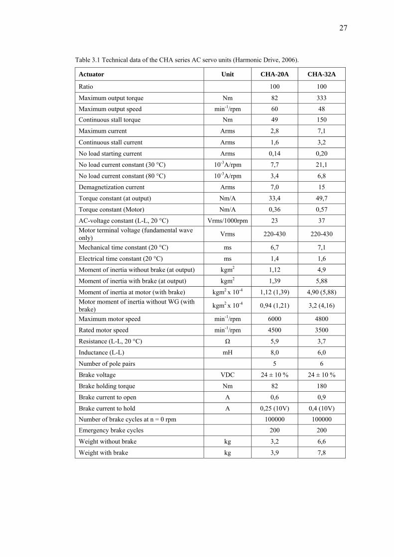
27
Table 3.1 Technical data of the CHA series AC servo units (Harmonic Drive, 2006).
Actuator Unit CHA-20A CHA-32A
Ratio 100 100
Maximum output torque Nm 82 333
Maximum output speed min-1/rpm 60 48 Continuous stall torque Nm 49 150
Maximum current Arms 2,8 7,1
Continuous stall current Arms 1,6 3,2
No load starting current Arms 0,14 0,20
No load current constant (30 °C) 10-3A/rpm 7,7 21,1
No load current constant (80 °C) 10-3A/rpm 3,4 6,8
Demagnetization current Arms 7,0 15
Torque constant (at output) Nm/A 33,4 49,7
Torque constant (Motor) Nm/A 0,36 0,57
AC-voltage constant (L-L, 20 °C) Vrms/1000rpm 23 37 Motor terminal voltage (fundamental wave only) Vrms 220-430 220-430
Mechanical time constant (20 °C) ms 6,7 7,1
Electrical time constant (20 °C) ms 1,4 1,6
Moment of inertia without brake (at output) kgm2 1,12 4,9
Moment of inertia with brake (at output) kgm2 1,39 5,88
Moment of inertia at motor (with brake) kgm2 x 10-4 1,12 (1,39) 4,90 (5,88) Motor moment of inertia without WG (with brake) kgm2 x 10-4 0,94 (1,21) 3,2 (4,16)
Maximum motor speed min-1/rpm 6000 4800
Rated motor speed min-1/rpm 4500 3500
Resistance (L-L, 20 °C) Ω 5,9 3,7
Inductance (L-L) mH 8,0 6,0
Number of pole pairs 5 6
Brake voltage VDC 24 ± 10 % 24 ± 10 %
Brake holding torque Nm 82 180
Brake current to open A 0,6 0,9
Brake current to hold A 0,25 (10V) 0,4 (10V)
Number of brake cycles at n = 0 rpm 100000 100000
Emergency brake cycles 200 200
Weight without brake kg 3,2 6,6
Weight with brake kg 3,9 7,8
28
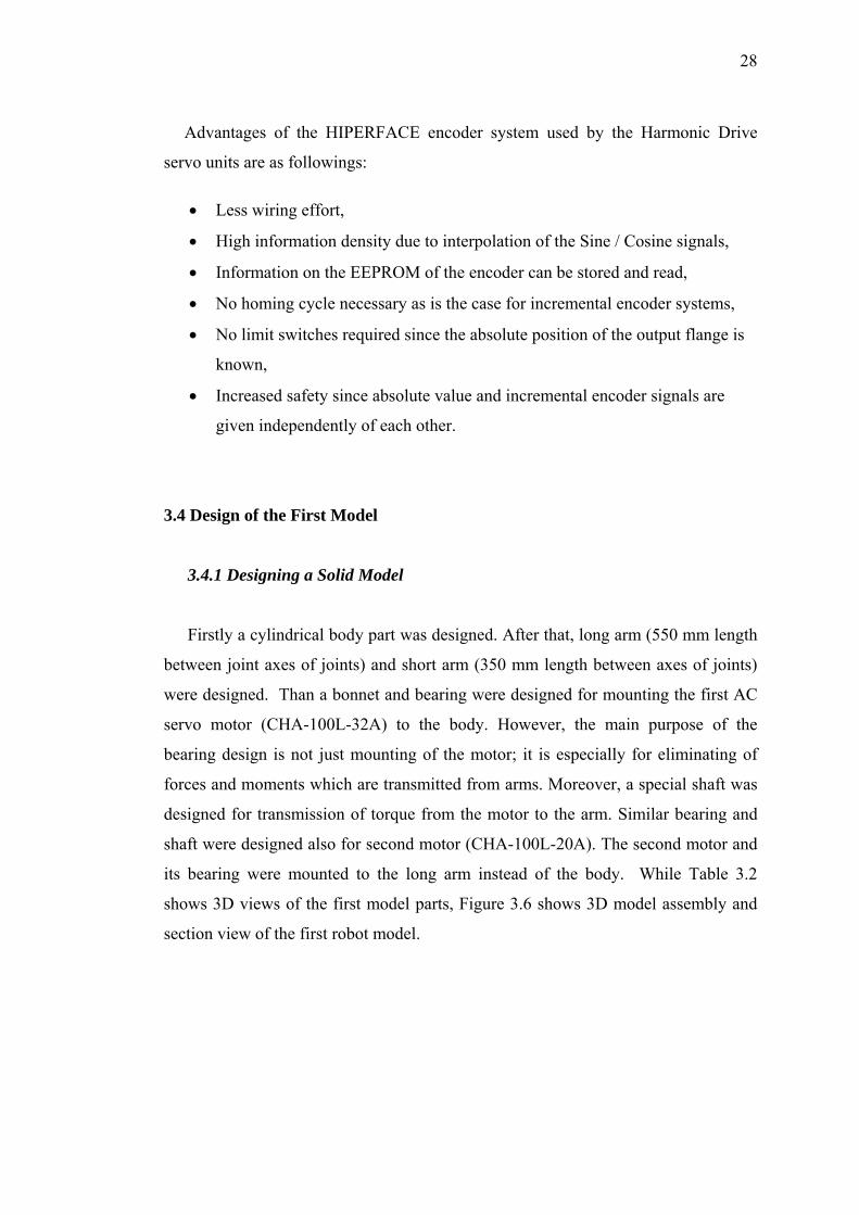
Advantages of the HIPERFACE encoder system used by the Harmonic Drive
servo units are as followings:
• Less wiring effort,
• High information density due to interpolation of the Sine / Cosine signals,
• Information on the EEPROM of the encoder can be stored and read,
• No homing cycle necessary as is the case for incremental encoder systems,
• No limit switches required since the absolute position of the output flange is
known,
• Increased safety since absolute value and incremental encoder signals are
given independently of each other.
3.4 Design of the First Model
3.4.1 Designing a Solid Model
Firstly a cylindrical body part was designed. After that, long arm (550 mm length
between joint axes of joints) and short arm (350 mm length between axes of joints)
were designed. Than a bonnet and bearing were designed for mounting the first AC
servo motor (CHA-100L-32A) to the body. However, the main purpose of the
bearing design is not just mounting of the motor; it is especially for eliminating of
forces and moments which are transmitted from arms. Moreover, a special shaft was
designed for transmission of torque from the motor to the arm. Similar bearing and
shaft were designed also for second motor (CHA-100L-20A). The second motor and
its bearing were mounted to the long arm instead of the body. While Table 3.2
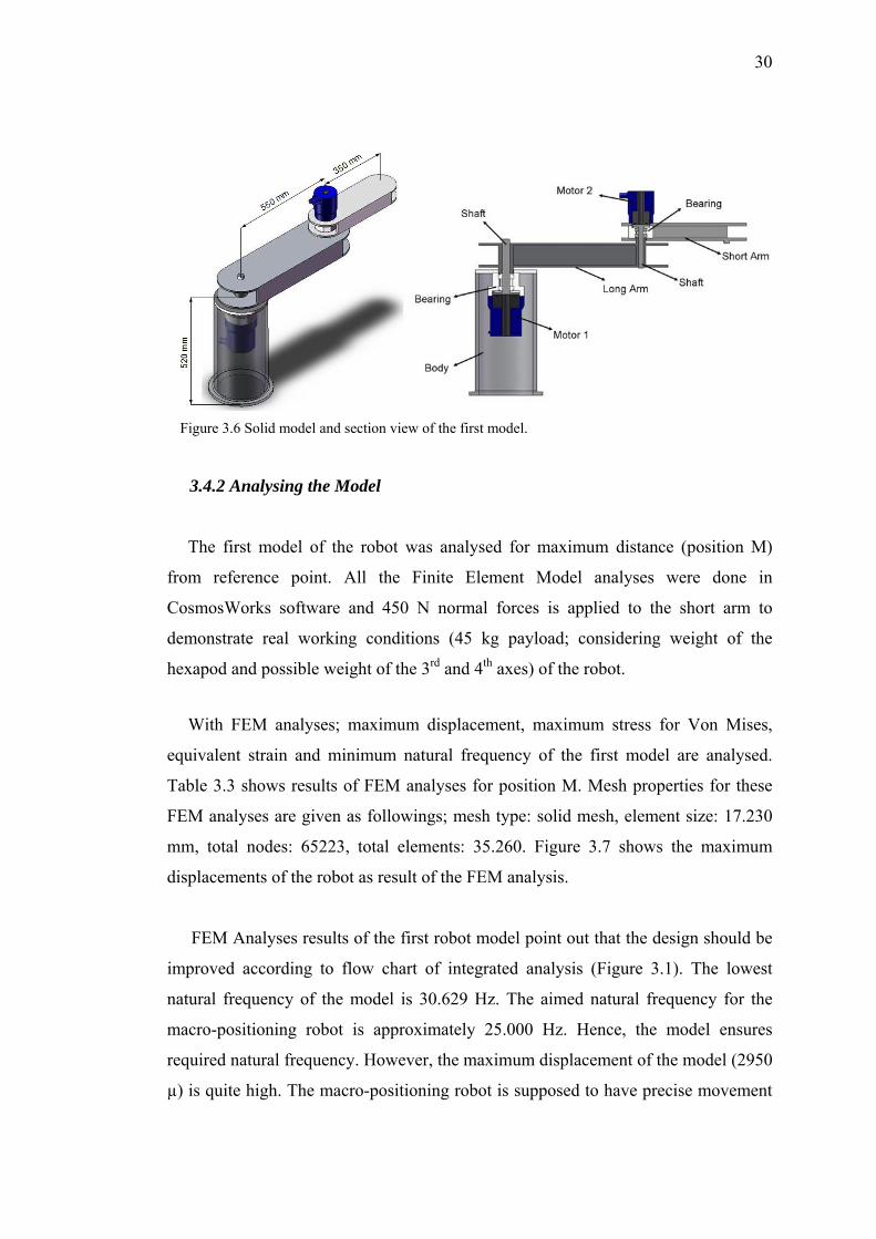
shows 3D views of the first model parts, Figure 3.6 shows 3D model assembly and
section view of the first robot model.
29
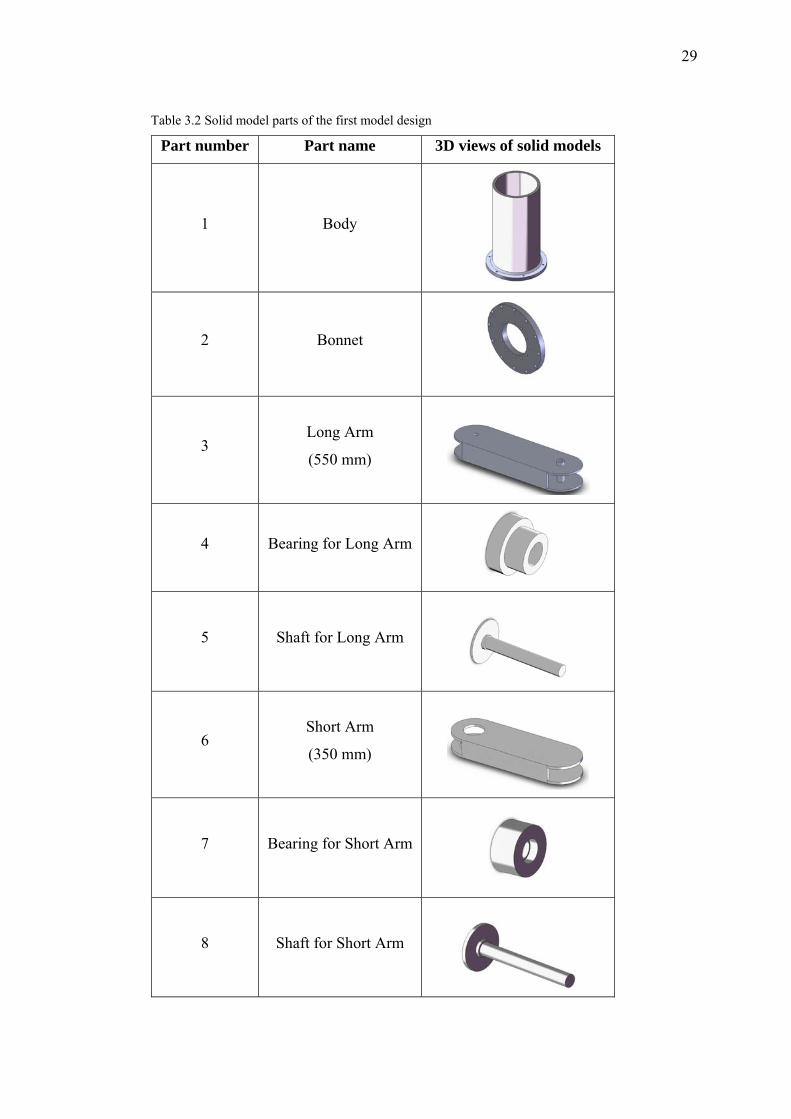
Table 3.2 Solid model parts of the first model design
Part number Part name 3D views of solid models
1 Body
2 Bonnet
3 Long Arm
(550 mm)
4 Bearing for Long Arm
5 Shaft for Long Arm
6 Short Arm
(350 mm)
7 Bearing for Short Arm
8 Shaft for Short Arm
30
Figure 3.6 Solid model and section view of the first model.
3.4.2 Analysing the Model
The first model of the robot was analysed for maximum distance (position M)
from reference point. All the Finite Element Model analyses were done in
CosmosWorks software and 450 N normal forces is applied to the short arm to
demonstrate real working conditions (45 kg payload; considering weight of the
hexapod and possible weight of the 3rd and 4th axes) of the robot.
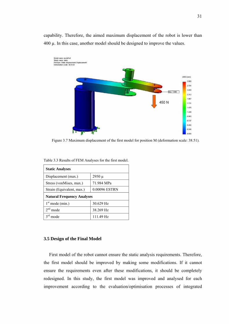
With FEM analyses; maximum displacement, maximum stress for Von Mises,
equivalent strain and minimum natural frequency of the first model are analysed.
Table 3.3 shows results of FEM analyses for position M. Mesh properties for these
FEM analyses are given as followings; mesh type: solid mesh, element size: 17.230
mm, total nodes: 65223, total elements: 35.260. Figure 3.7 shows the maximum
displacements of the robot as result of the FEM analysis.
FEM Analyses results of the first robot model point out that the design should be
improved according to flow chart of integrated analysis (Figure 3.1). The lowest
natural frequency of the model is 30.629 Hz. The aimed natural frequency for the
macro-positioning robot is approximately 25.000 Hz. Hence, the model ensures
required natural frequency. However, the maximum displacement of the model (2950
µ) is quite high. The macro-positioning robot is supposed to have precise movement
31
capability. Therefore, the aimed maximum displacement of the robot is lower than
400 µ. In this case, another model should be designed to improve the values.
Figure 3.7 Maximum displacement of the first model for position M (deformation scale: 38.51).
Table 3.3 Results of FEM Analyses for the first model.
Static Analyses
Displacement (max.) 2950 µ
Stress (vonMises, max.) 71.984 MPa
Strain (Equivalent, max.) 0.00096 ESTRN
Natural Frequency Analyses
1st mode (min.) 30.629 Hz
2nd mode 38.269 Hz
3rd mode 111.49 Hz
3.5 Design of the Final Model
First model of the robot cannot ensure the static analysis requirements. Therefore,
the first model should be improved by making some modifications. If it cannot
ensure the requirements even after these modifications, it should be completely
redesigned. In this study, the first model was improved and analysed for each
improvement according to the evaluation/optimisation processes of integrated
32
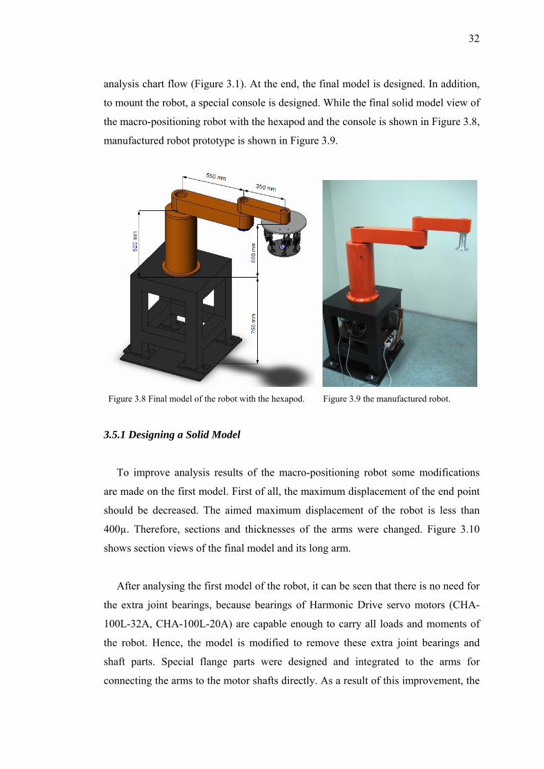
analysis chart flow (Figure 3.1). At the end, the final model is designed. In addition,
to mount the robot, a special console is designed. While the final solid model view of
the macro-positioning robot with the hexapod and the console is shown in Figure 3.8,
manufactured robot prototype is shown in Figure 3.9.
Figure 3.8 Final model of the robot with the hexapod. Figure 3.9 the manufactured robot.
3.5.1 Designing a Solid Model
To improve analysis results of the macro-positioning robot some modifications
are made on the first model. First of all, the maximum displacement of the end point
should be decreased. The aimed maximum displacement of the robot is less than
400µ. Therefore, sections and thicknesses of the arms were changed. Figure 3.10
shows section views of the final model and its long arm.
After analysing the first model of the robot, it can be seen that there is no need for
the extra joint bearings, because bearings of Harmonic Drive servo motors (CHA-
100L-32A, CHA-100L-20A) are capable enough to carry all loads and moments of
the robot. Hence, the model is modified to remove these extra joint bearings and
shaft parts. Special flange parts were designed and integrated to the arms for
connecting the arms to the motor shafts directly. As a result of this improvement, the
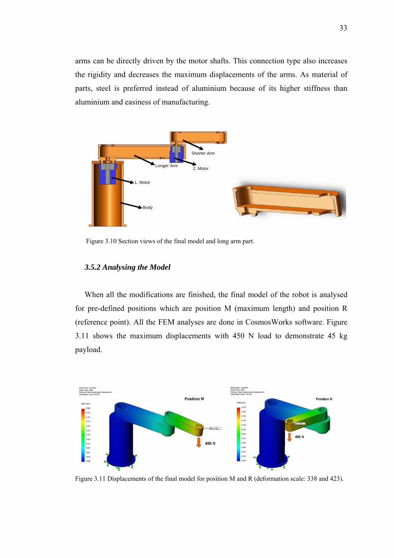
33
arms can be directly driven by the motor shafts. This connection type also increases
the rigidity and decreases the maximum displacements of the arms. As material of
parts, steel is preferred instead of aluminium because of its higher stiffness than
aluminium and easiness of manufacturing.
Shorter Arm
Longer Arm 2. Motor
1. Motor
Body
Figure 3.10 Section views of the final model and long arm part.
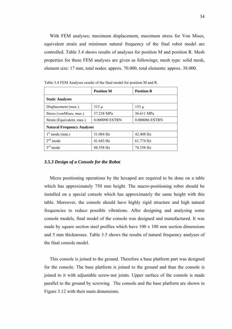
3.5.2 Analysing the Model
When all the modifications are finished, the final model of the robot is analysed
for pre-defined positions which are position M (maximum length) and position R
(reference point). All the FEM analyses are done in CosmosWorks software. Figure
3.11 shows the maximum displacements with 450 N load to demonstrate 45 kg
payload.
Figure 3.11 Displacements of the final model for position M and R (deformation scale: 338 and 423).
34
With FEM analyses; maximum displacement, maximum stress for Von Mises,
equivalent strain and minimum natural frequency of the final robot model are
controlled. Table 3.4 shows results of analyses for position M and position R. Mesh
properties for these FEM analyses are given as followings; mesh type: solid mesh,
element size: 17 mm, total nodes: approx. 70.000, total elements: approx. 38.000.
Table 3.4 FEM Analyses results of the final model for position M and R.
Position M Position R
Static Analyses
Displacement (max.) 312 µ 153 µ
Stress (vonMises, max.) 37.238 MPa 36.611 MPa
Strain (Equivalent, max.) 0.000090 ESTRN 0.000086 ESTRN
Natural Frequency Analyses
1st mode (min.) 31.084 Hz 42.408 Hz
2nd mode 41.643 Hz 61.774 Hz
3rd mode 88.558 Hz 74.358 Hz
3.5.3 Design of a Console for the Robot
Micro positioning operations by the hexapod are required to be done on a table
which has approximately 750 mm height. The macro-positioning robot should be
installed on a special console which has approximately the same height with this
table. Moreover, the console should have highly rigid structure and high natural
frequencies to reduce possible vibrations. After designing and analysing some
console models, final model of the console was designed and manufactured. It was
made by square section steel profiles which have 100 x 100 mm section dimensions
and 5 mm thicknesses. Table 3.5 shows the results of natural frequency analyses of
the final console model.
This console is joined to the ground. Therefore a base platform part was designed
for the console. The base platform is joined to the ground and than the console is
joined to it with adjustable screw-nut joints. Upper surface of the console is made
parallel to the ground by screwing. The console and the base platform are shown in
Figure 3.12 with their main dimensions.
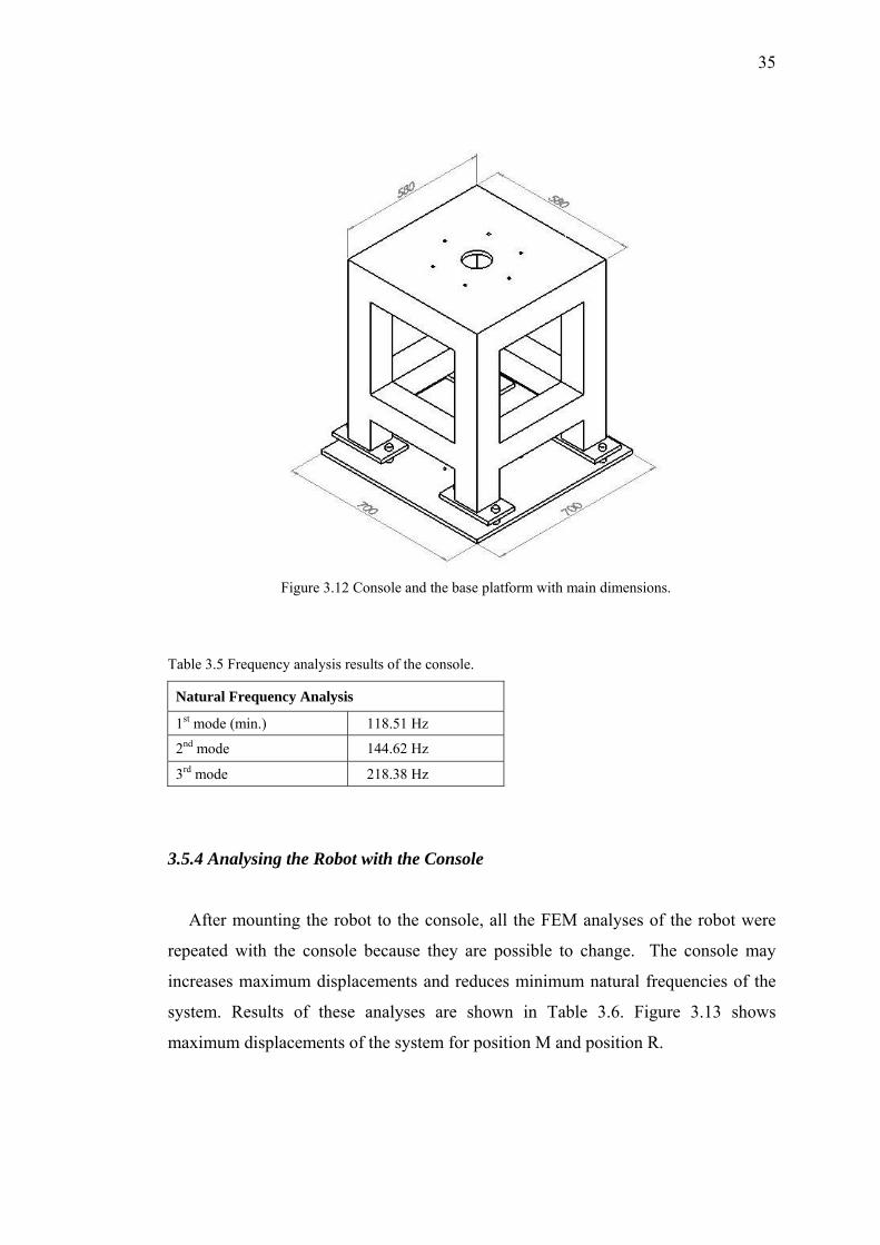
35
Figure 3.12 Console and the base platform with main dimensions.
Table 3.5 Frequency analysis results of the console.
Natural Frequency Analysis
1st mode (min.) 118.51 Hz
2nd mode 144.62 Hz
3rd mode 218.38 Hz
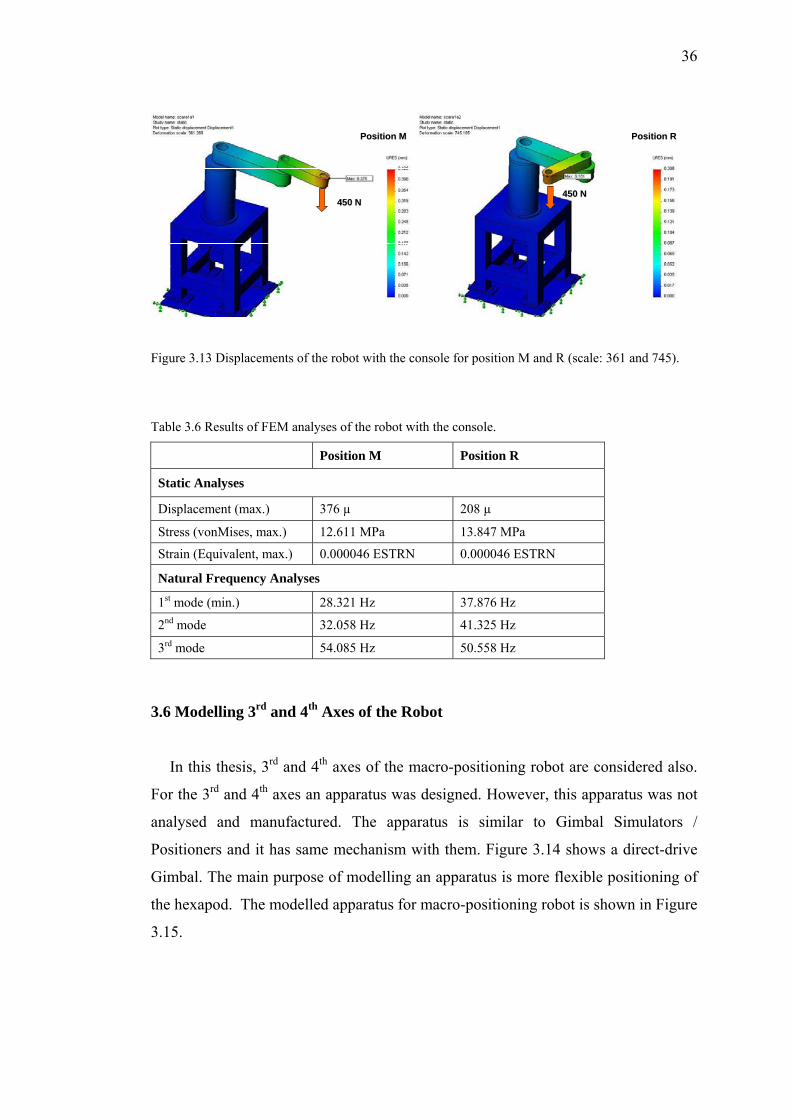
3.5.4 Analysing the Robot with the Console
After mounting the robot to the console, all the FEM analyses of the robot were
repeated with the console because they are possible to change. The console may
increases maximum displacements and reduces minimum natural frequencies of the
system. Results of these analyses are shown in Table 3.6. Figure 3.13 shows
maximum displacements of the system for position M and position R.
36
450 N450 N
PositionPosition MM
450 N450 N
PositionPosition MM
450 N450 N
PositionPosition RR
450 N450 N
PositionPosition RR
Figure 3.13 Displacements of the robot with the console for position M and R (scale: 361 and 745).
Table 3.6 Results of FEM analyses of the robot with the console.
Position M Position R
Static Analyses
Displacement (max.) 376 µ 208 µ
Stress (vonMises, max.) 12.611 MPa 13.847 MPa
Strain (Equivalent, max.) 0.000046 ESTRN 0.000046 ESTRN
Natural Frequency Analyses
1st mode (min.) 28.321 Hz 37.876 Hz
2nd mode 32.058 Hz 41.325 Hz
3rd mode 54.085 Hz 50.558 Hz
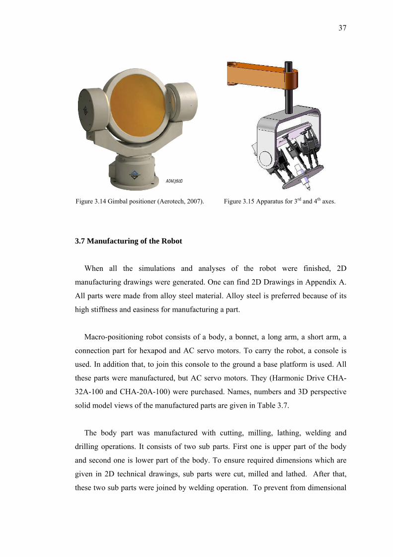
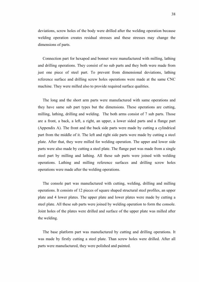
3.6 Modelling 3rd and 4th Axes of the Robot
In this thesis, 3rd and 4th axes of the macro-positioning robot are considered also.
For the 3rd and 4th axes an apparatus was designed. However, this apparatus was not
analysed and manufactured. The apparatus is similar to Gimbal Simulators /
Positioners and it has same mechanism with them. Figure 3.14 shows a direct-drive
Gimbal. The main purpose of modelling an apparatus is more flexible positioning of
the hexapod. The modelled apparatus for macro-positioning robot is shown in Figure
3.15.
37
Figure 3.14 Gimbal positioner (Aerotech, 2007). Figure 3.15 Apparatus for 3rd and 4th axes.
3.7 Manufacturing of the Robot
When all the simulations and analyses of the robot were finished, 2D
manufacturing drawings were generated. One can find 2D Drawings in Appendix A.
All parts were made from alloy steel material. Alloy steel is preferred because of its
high stiffness and easiness for manufacturing a part.
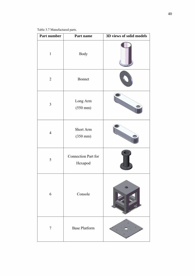
Macro-positioning robot consists of a body, a bonnet, a long arm, a short arm, a
connection part for hexapod and AC servo motors. To carry the robot, a console is
used. In addition that, to join this console to the ground a base platform is used. All
these parts were manufactured, but AC servo motors. They (Harmonic Drive CHA-
32A-100 and CHA-20A-100) were purchased. Names, numbers and 3D perspective
solid model views of the manufactured parts are given in Table 3.7.
The body part was manufactured with cutting, milling, lathing, welding and
drilling operations. It consists of two sub parts. First one is upper part of the body
and second one is lower part of the body. To ensure required dimensions which are
given in 2D technical drawings, sub parts were cut, milled and lathed. After that,
these two sub parts were joined by welding operation. To prevent from dimensional
38
deviations, screw holes of the body were drilled after the welding operation because
welding operation creates residual stresses and these stresses may change the
dimensions of parts.
Connection part for hexapod and bonnet were manufactured with milling, lathing
and drilling operations. They consist of no sub parts and they both were made from
just one piece of steel part. To prevent from dimensional deviations, lathing
reference surface and drilling screw holes operations were made at the same CNC
machine. They were milled also to provide required surface qualities.
The long and the short arm parts were manufactured with same operations and
they have same sub part types but the dimensions. These operations are cutting,
milling, lathing, drilling and welding. The both arms consist of 7 sub parts. Those
are a front, a back, a left, a right, an upper, a lower sided parts and a flange part
(Appendix A). The front and the back side parts were made by cutting a cylindrical
part from the middle of it. The left and right side parts were made by cutting a steel
plate. After that, they were milled for welding operation. The upper and lower side
parts were also made by cutting a steel plate. The flange part was made from a single
steel part by milling and lathing. All these sub parts were joined with welding
operations. Lathing and milling reference surfaces and drilling screw holes
operations were made after the welding operations.
The console part was manufactured with cutting, welding, drilling and milling
operations. It consists of 12 pieces of square shaped structural steel profiles, an upper
plate and 4 lower plates. The upper plate and lower plates were made by cutting a
steel plate. All these sub parts were joined by welding operation to form the console.
Joint holes of the plates were drilled and surface of the upper plate was milled after
the welding.
The base platform part was manufactured by cutting and drilling operations. It
was made by firstly cutting a steel plate. Than screw holes were drilled. After all
parts were manufactured, they were polished and painted.
39
Assembly of the robot is made by as the following order: Firstly, the base
platform is fixed on the ground and the console is fixed on it. The upper surface of
the console must be parallel to the ground. If it is not, the height of it is adjusted by
screwing the nuts of the base platform. Secondly, the body part is joined to the
console by screwing. After that, body of the first AC servo motor (CHA-32A-100) is
joined to the bonnet is joined to the body by screwing. Than the body of the second
AC servo motor (CHA-20A-100) is joined to the long arm and the flange of the long
arm is joined to the shaft of the first motor. Flange of the short arm is joined to the
shaft of the second motor by screwing. Hexapod is joined to the short arm via a
connection part. After finishing the assembly of parts, cable installations are done.
40
Table 3.7 Manufactured parts.
Part number Part name 3D views of solid models
1 Body
2 Bonnet
3 Long Arm
(550 mm)
4 Short Arm
(350 mm)
5 Connection Part for
Hexapod
6 Console
7 Base Platform
CHAPTER FOUR
CONTROLLING AND SIMULATION OF
THE MACRO-POSITIONING ROBOT
4.1 Introduction
In this chapter, it is purposed to control and simulate the macro-positioning robot.
First of all, a control system is designed for the robot and a control panel is built. The
robot is controlled by a developed VisualBASIC program. This program runs with
CosmosMotion together and takes outputs of it as inputs (Karagülle et al., 2007).
Simulation is performed by CosmosMotion program. Data of inverse kinematic
solution is giving by the simulation. The model for simulation has same dimensions
and properties with final robot model.
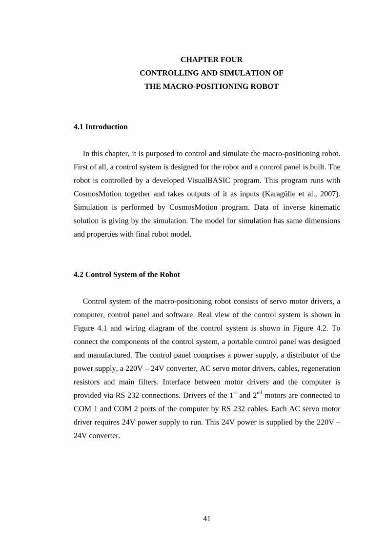
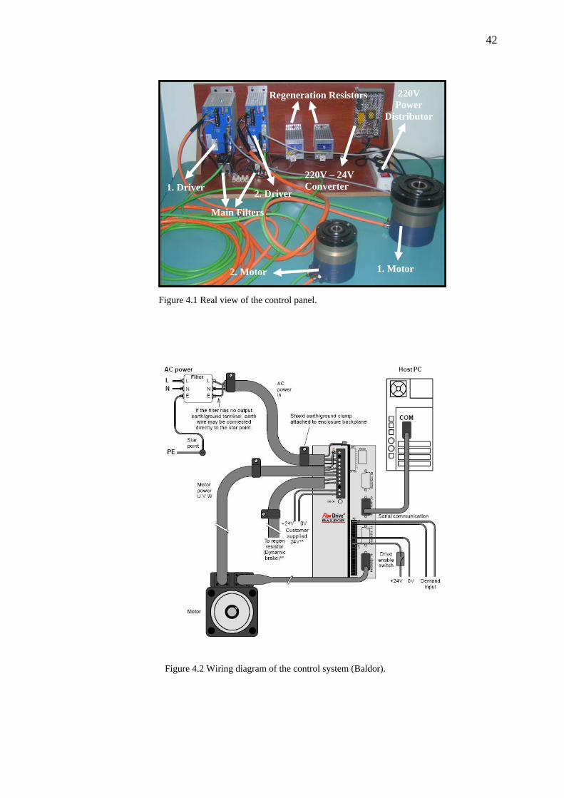
4.2 Control System of the Robot
Control system of the macro-positioning robot consists of servo motor drivers, a
computer, control panel and software. Real view of the control system is shown in
Figure 4.1 and wiring diagram of the control system is shown in Figure 4.2. To
connect the components of the control system, a portable control panel was designed
and manufactured. The control panel comprises a power supply, a distributor of the
power supply, a 220V – 24V converter, AC servo motor drivers, cables, regeneration
resistors and main filters. Interface between motor drivers and the computer is
provided via RS 232 connections. Drivers of the 1st and 2nd motors are connected to
COM 1 and COM 2 ports of the computer by RS 232 cables. Each AC servo motor
driver requires 24V power supply to run. This 24V power is supplied by the 220V –
24V converter.
41
42
Figure 4.1 Real view of the control panel.
Figure 4.2 Wiring diagram of the control system (Baldor).
1. Motor
220V Power
Distributor
2. Motor
Regeneration Resistors
220V – 24V Converter
1. Motor
1. Driver 2. Driver
Main Filters
43
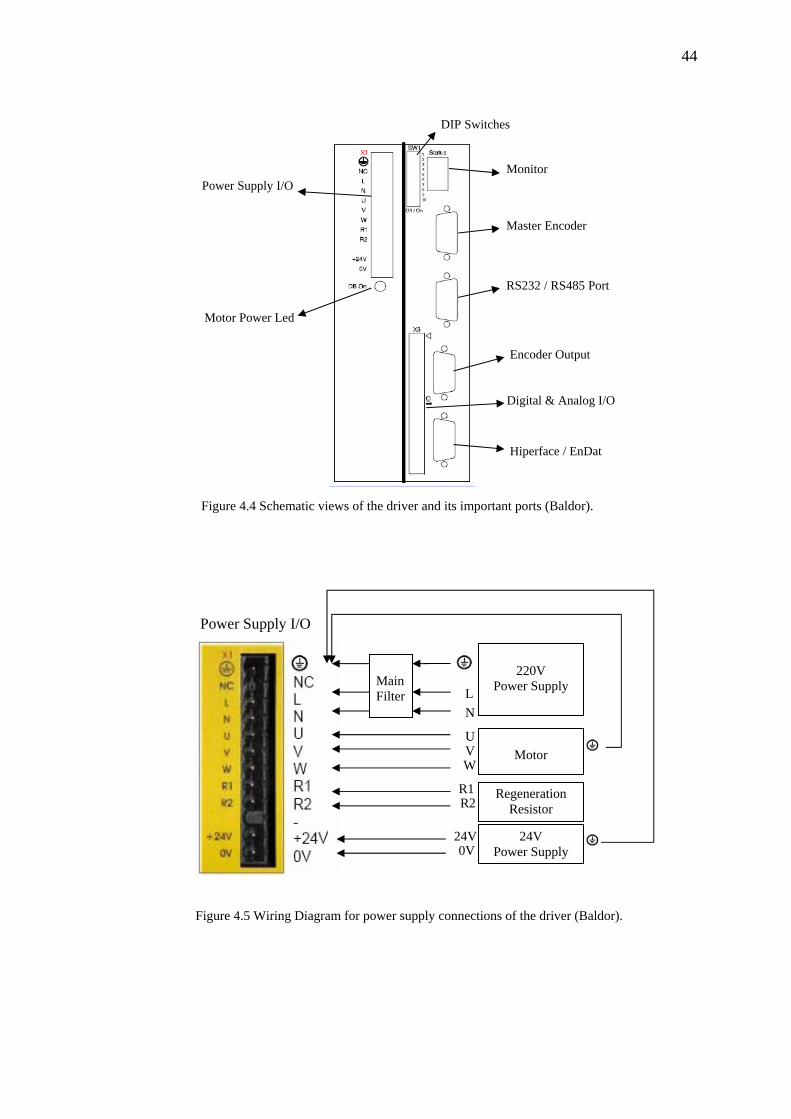
Schematic view of AC servo motor driver is shown in Figure 4.4. When motor is
activated by the driver, “Motor Power Led” turns on. “Monitor” shows the actual
mode of the driver and it is also used to get error codes from the driver. Encoder
output cable which comes from the motor is connected to “Hiperface / EnDat” port
of the driver. “RS 232 / RS 485 port” of the driver is used for Computer – Driver
communication. “Encoder Output” port makes possible to receive the encoder data of
the motor for other systems. “Power Supply I/O” port is used for 220V and 24V
power supply, motor power cable and regeneration resistor connections. In Figure
4.5, wiring diagram of the Power Supply I/O port is shown detailed.
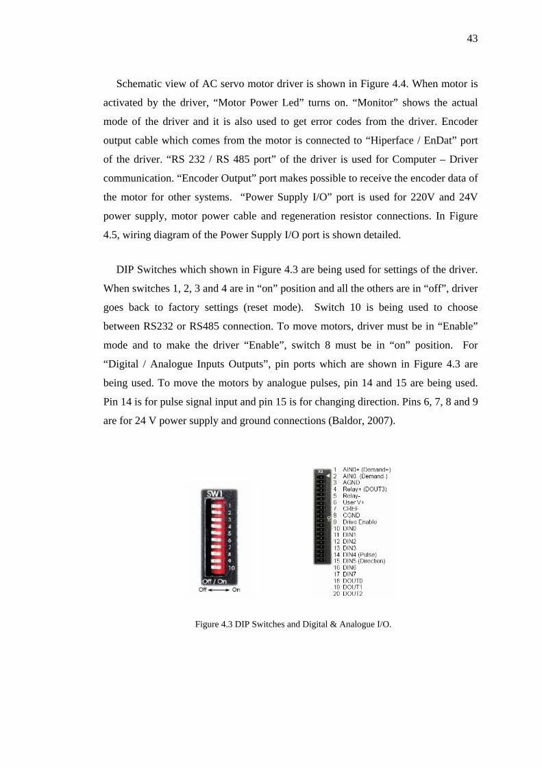
DIP Switches which shown in Figure 4.3 are being used for settings of the driver.
When switches 1, 2, 3 and 4 are in “on” position and all the others are in “off”, driver
goes back to factory settings (reset mode). Switch 10 is being used to choose
between RS232 or RS485 connection. To move motors, driver must be in “Enable”
mode and to make the driver “Enable”, switch 8 must be in “on” position. For
“Digital / Analogue Inputs Outputs”, pin ports which are shown in Figure 4.3 are
being used. To move the motors by analogue pulses, pin 14 and 15 are being used.
Pin 14 is for pulse signal input and pin 15 is for changing direction. Pins 6, 7, 8 and 9
are for 24 V power supply and ground connections (Baldor, 2007).
Figure 4.3 DIP Switches and Digital & Analogue I/O.
44
DIP Switches
Figure 4.4 Schematic views of the driver and its important ports (Baldor).
Figure 4.5 Wiring Diagram for power supply connections of the driver (Baldor).
Digital & Analog I/O
Monitor
RS232 / RS485 Port
Encoder Output
Hiperface / EnDat
Power Supply I/O
Motor Power Led
Master Encoder
24V Power Supply
Power Supply I/O
24V 0V
Regeneration Resistor
R1 R2
Motor V
W
U
220V Main Filter
Power Supply
N L
45
4.3 Simulation and Control of the Robot
4.3.1 Developed VisualBASIC Program for Controlling
Position control is applied to the macro-positioning robot via servo motors. Point
– to – point applications are processed. PC-based motion control is achieved over RS
232 ports. In order to start and stop movement simultaneously, velocities are
determined by using interpolation. The maximum velocities are chosen as 3800 rpm
for first axis and 5000 rpm for second axis to protect motors. The slowest servo
motor with respect to the motion moves less.
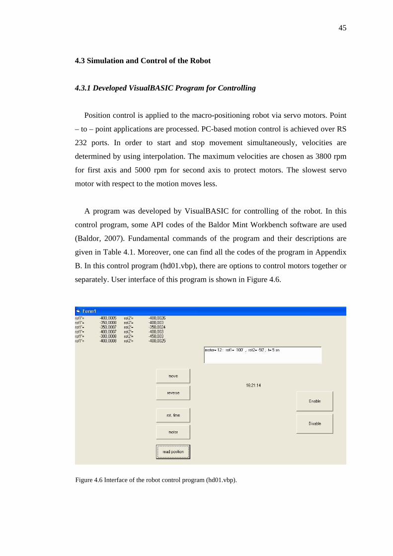
A program was developed by VisualBASIC for controlling of the robot. In this
control program, some API codes of the Baldor Mint Workbench software are used
(Baldor, 2007). Fundamental commands of the program and their descriptions are
given in Table 4.1. Moreover, one can find all the codes of the program in Appendix
B. In this control program (hd01.vbp), there are options to control motors together or
separately. User interface of this program is shown in Figure 4.6.
Figure 4.6 Interface of the robot control program (hd01.vbp).
46
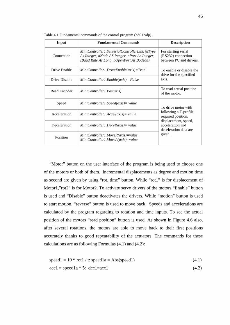
Table 4.1 Fundamental commands of the control program (hd01.vdp).
Input Fundamental Commands Description
Connection MintController1.SetSerialControllerLink (nType As Integer, nNode AS Integer, nPort As Integer, IBaud Rate As Long, bOpenPort As Bodean)
For starting serial (RS232) connection between PC and drivers.
Drive Enable MintController1.DriveEnable(axis)=True
Drive Disable MintController1.Enable(axis)= False
To enable or disable the drive for the specified axis.
Read Encoder MintController1.Pos(axis) To read actual position of the motor.
Speed MintController1.Speed(axis)= value
Acceleration MintController1.Accel(axis)= value
Deceleration MintController1.Decel(axis)= value
Position MintController1.MoveR(axis)=value MintController1.MoveA(axis)=value
To drive motor with following a T-profile, required position, displacement, speed, acceleration and deceleration data are given.
“Motor” button on the user interface of the program is being used to choose one
of the motors or both of them. Incremental displacements as degree and motion time
as second are given by using “rot, time” button. While “rot1” is for displacement of
Motor1,”rot2” is for Motor2. To activate servo drivers of the motors “Enable” button
is used and “Disable” button deactivates the drivers. While “motion” button is used
to start motion, “reverse” button is used to move back. Speeds and accelerations are
calculated by the program regarding to rotation and time inputs. To see the actual
position of the motors “read position” button is used. As shown in Figure 4.6 also,
after several rotations, the motors are able to move back to their first positions
accurately thanks to good repeatability of the actuators. The commands for these
calculations are as following Formulas (4.1) and (4.2):
speed1 = 10 * rot1 / t: speed1a = Abs(speed1) (4.1)
acc1 = speed1a * 5: dcc1=acc1 (4.2)
47
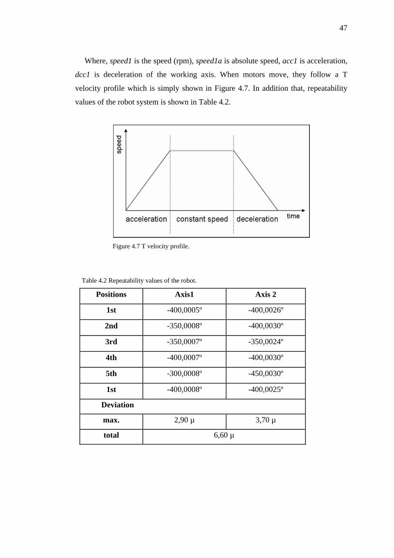
Where, speed1 is the speed (rpm), speed1a is absolute speed, acc1 is acceleration,
dcc1 is deceleration of the working axis. When motors move, they follow a T
velocity profile which is simply shown in Figure 4.7. In addition that, repeatability
values of the robot system is shown in Table 4.2.
Figure 4.7 T velocity profile.
Table 4.2 Repeatability values of the robot.
Positions Axis1 Axis 2
1st -400,0005º -400,0026º
2nd -350,0008º -400,0030º
3rd -350,0007º -350,0024º
4th -400,0007º -400,0030º
5th -300,0008º -450,0030º
1st -400,0008º -400,0025º
Deviation
max. 2,90 µ 3,70 µ
total 6,60 µ
48
4.3.2 Modelling of the Robot by a Visual BASIC program
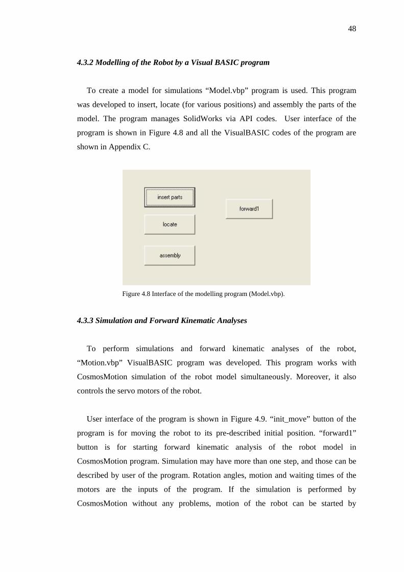
To create a model for simulations “Model.vbp” program is used. This program
was developed to insert, locate (for various positions) and assembly the parts of the
model. The program manages SolidWorks via API codes. User interface of the
program is shown in Figure 4.8 and all the VisualBASIC codes of the program are
shown in Appendix C.
Figure 4.8 Interface of the modelling program (Model.vbp).
4.3.3 Simulation and Forward Kinematic Analyses
To perform simulations and forward kinematic analyses of the robot,
“Motion.vbp” VisualBASIC program was developed. This program works with
CosmosMotion simulation of the robot model simultaneously. Moreover, it also
controls the servo motors of the robot.
User interface of the program is shown in Figure 4.9. “init_move” button of the
program is for moving the robot to its pre-described initial position. “forward1”
button is for starting forward kinematic analysis of the robot model in
CosmosMotion program. Simulation may have more than one step, and those can be
described by user of the program. Rotation angles, motion and waiting times of the
motors are the inputs of the program. If the simulation is performed by
CosmosMotion without any problems, motion of the robot can be started by
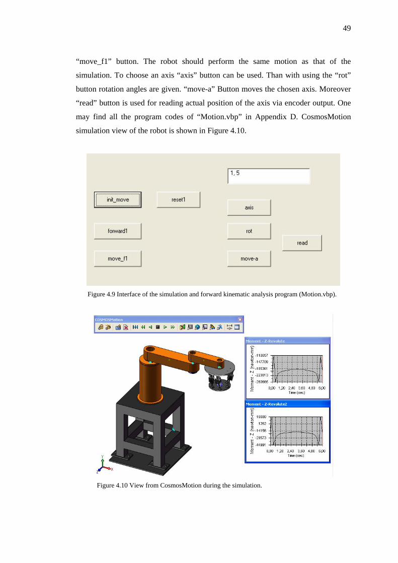
49
“move_f1” button. The robot should perform the same motion as that of the
simulation. To choose an axis “axis” button can be used. Than with using the “rot”
button rotation angles are given. “move-a” Button moves the chosen axis. Moreover
“read” button is used for reading actual position of the axis via encoder output. One
may find all the program codes of “Motion.vbp” in Appendix D. CosmosMotion
simulation view of the robot is shown in Figure 4.10.
Figure 4.9 Interface of the simulation and forward kinematic analysis program (Motion.vbp).
Figure 4.10 View from CosmosMotion during the simulation.
50
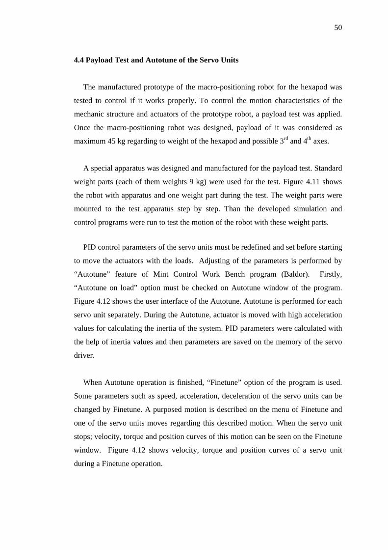
4.4 Payload Test and Autotune of the Servo Units
The manufactured prototype of the macro-positioning robot for the hexapod was
tested to control if it works properly. To control the motion characteristics of the
mechanic structure and actuators of the prototype robot, a payload test was applied.
Once the macro-positioning robot was designed, payload of it was considered as
maximum 45 kg regarding to weight of the hexapod and possible 3rd and 4th axes.
A special apparatus was designed and manufactured for the payload test. Standard
weight parts (each of them weights 9 kg) were used for the test. Figure 4.11 shows
the robot with apparatus and one weight part during the test. The weight parts were
mounted to the test apparatus step by step. Than the developed simulation and
control programs were run to test the motion of the robot with these weight parts.
PID control parameters of the servo units must be redefined and set before starting
to move the actuators with the loads. Adjusting of the parameters is performed by
“Autotune” feature of Mint Control Work Bench program (Baldor). Firstly,
“Autotune on load” option must be checked on Autotune window of the program.
Figure 4.12 shows the user interface of the Autotune. Autotune is performed for each
servo unit separately. During the Autotune, actuator is moved with high acceleration
values for calculating the inertia of the system. PID parameters were calculated with
the help of inertia values and then parameters are saved on the memory of the servo
driver.
When Autotune operation is finished, “Finetune” option of the program is used.
Some parameters such as speed, acceleration, deceleration of the servo units can be
changed by Finetune. A purposed motion is described on the menu of Finetune and
one of the servo units moves regarding this described motion. When the servo unit
stops; velocity, torque and position curves of this motion can be seen on the Finetune
window. Figure 4.12 shows velocity, torque and position curves of a servo unit
during a Finetune operation.
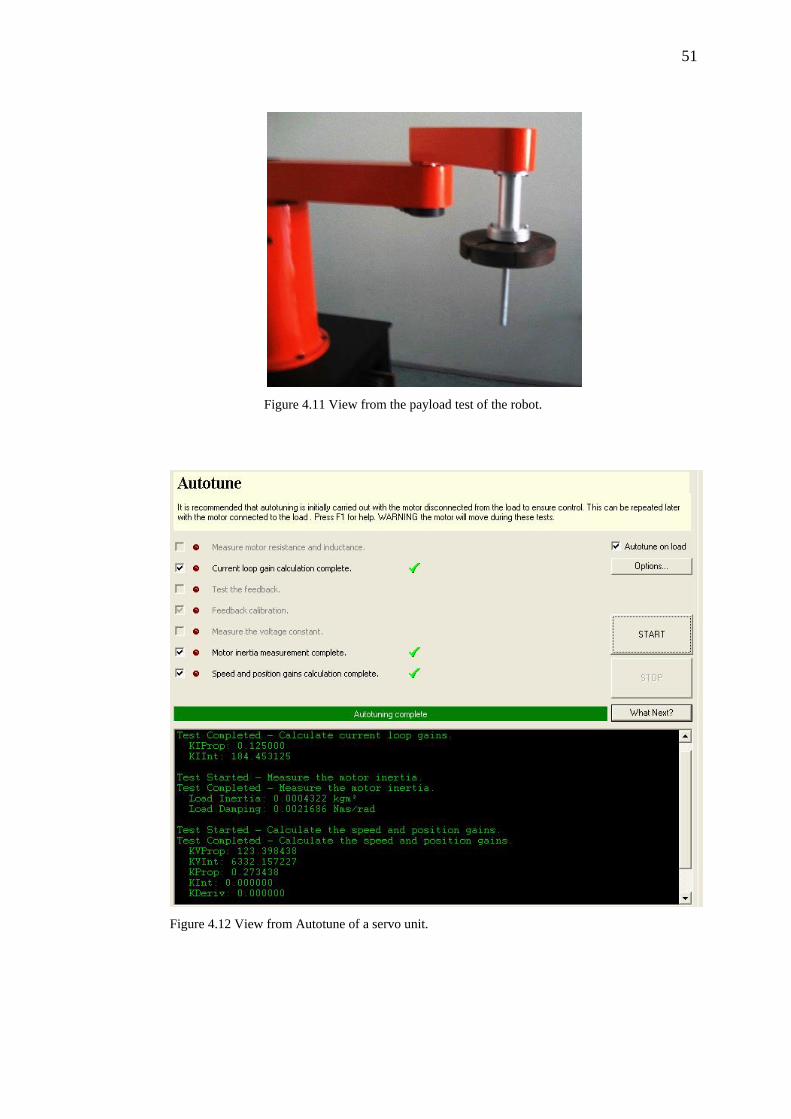
51
Figure 4.11 View from the payload test of the robot.
Figure 4.12 View from Autotune of a servo unit.
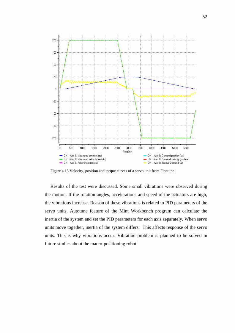
52
Figure 4.13 Velocity, position and torque curves of a servo unit from Finetune.
Results of the test were discussed. Some small vibrations were observed during
the motion. If the rotation angles, accelerations and speed of the actuators are high,
the vibrations increase. Reason of these vibrations is related to PID parameters of the
servo units. Autotune feature of the Mint Workbench program can calculate the
inertia of the system and set the PID parameters for each axis separately. When servo
units move together, inertia of the system differs. This affects response of the servo
units. This is why vibrations occur. Vibration problem is planned to be solved in
future studies about the macro-positioning robot.
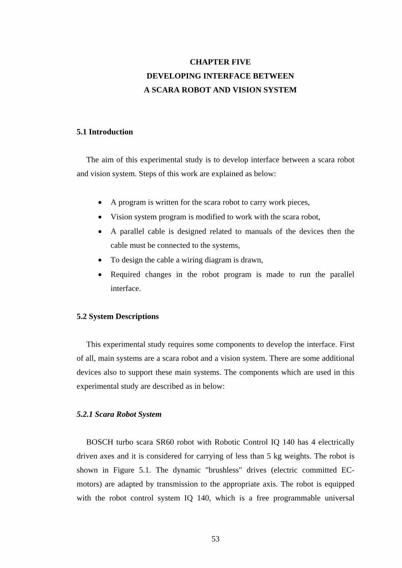
CHAPTER FIVE
DEVELOPING INTERFACE BETWEEN
A SCARA ROBOT AND VISION SYSTEM
5.1 Introduction
The aim of this experimental study is to develop interface between a scara robot
and vision system. Steps of this work are explained as below:
• A program is written for the scara robot to carry work pieces,
• Vision system program is modified to work with the scara robot,
• A parallel cable is designed related to manuals of the devices then the
cable must be connected to the systems,
• To design the cable a wiring diagram is drawn,
• Required changes in the robot program is made to run the parallel
interface.
5.2 System Descriptions
This experimental study requires some components to develop the interface. First
of all, main systems are a scara robot and a vision system. There are some additional
devices also to support these main systems. The components which are used in this
experimental study are described as in below:
5.2.1 Scara Robot System
BOSCH turbo scara SR60 robot with Robotic Control IQ 140 has 4 electrically
driven axes and it is considered for carrying of less than 5 kg weights. The robot is
shown in Figure 5.1. The dynamic "brushless" drives (electric committed EC-
motors) are adapted by transmission to the appropriate axis. The robot is equipped
with the robot control system IQ 140, which is a free programmable universal
53
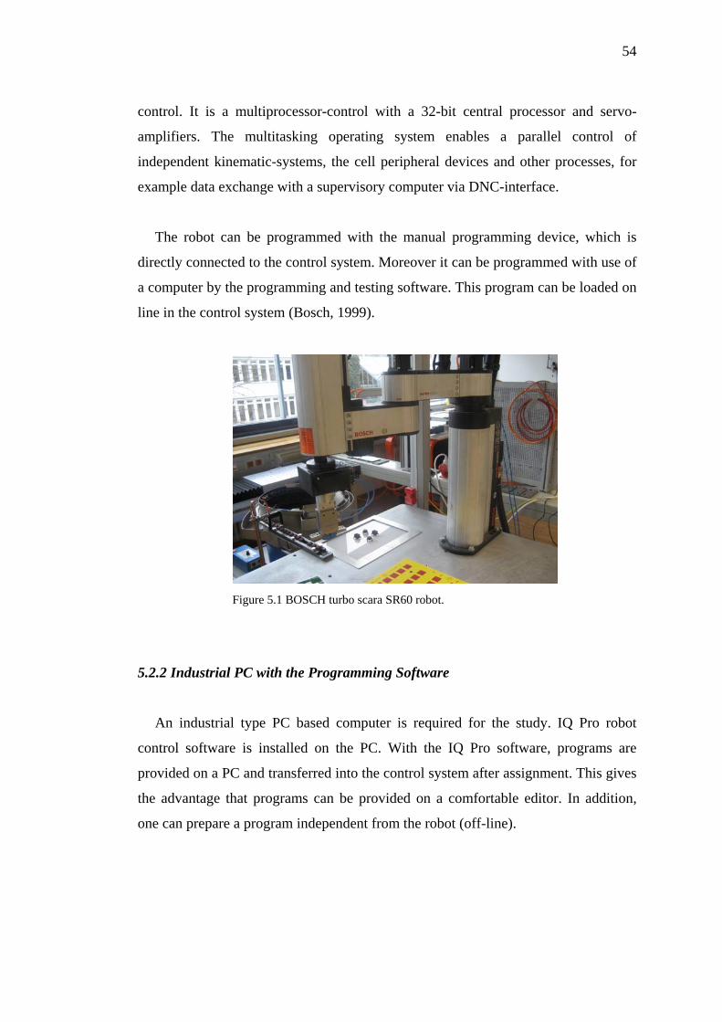
54
control. It is a multiprocessor-control with a 32-bit central processor and servo-
amplifiers. The multitasking operating system enables a parallel control of
independent kinematic-systems, the cell peripheral devices and other processes, for
example data exchange with a supervisory computer via DNC-interface.
The robot can be programmed with the manual programming device, which is
directly connected to the control system. Moreover it can be programmed with use of
a computer by the programming and testing software. This program can be loaded on
line in the control system (Bosch, 1999).
Figure 5.1 BOSCH turbo scara SR60 robot.
5.2.2 Industrial PC with the Programming Software
An industrial type PC based computer is required for the study. IQ Pro robot
control software is installed on the PC. With the IQ Pro software, programs are
provided on a PC and transferred into the control system after assignment. This gives
the advantage that programs can be provided on a comfortable editor. In addition,
one can prepare a program independent from the robot (off-line).
55
Program preparation is divided into three steps:
1. Edit > Write a program with the editor.
2. Translate > Translation of the program into machine code.
3. Transfer > Transmission of the program from PC into robotic control.
5.2.3 Vision System
The Industrial PC of the system was developed especially to use in industrial
environments. The Matsushita Industrial PC P400 provides ultimate convenience as a
result of:
• Service – friendly backplane technology,
• Mouse and keyboard ports in front and back,
• Integrated power supply for LED illumination,
• Removable hard drive.
PC Image checker P400 (Figure 5.2) is completely based on an image processing
system with high efficiency and reliability.
The image processing process can be divided into two steps:
1. Reading the picture. (Camera frame grabber is main storage of image checker.) 2. Examining and result process:
Picture - processing routines (checker) is implemented,
Spreadsheets work (check results in statistics, formulas, calibrations
process etc.),
Results transfer (values to the interfaces transfer),
Display results (camera picture, spreadsheet, checker results).
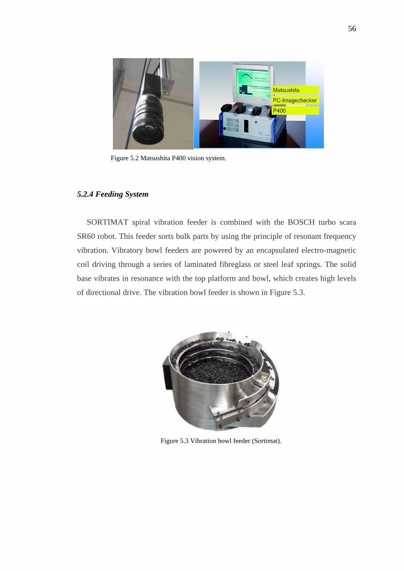
56
Figure 5.2 Matsushita P400 vision system.
5.2.4 Feeding System
SORTIMAT spiral vibration feeder is combined with the BOSCH turbo scara
SR60 robot. This feeder sorts bulk parts by using the principle of resonant frequency
vibration. Vibratory bowl feeders are powered by an encapsulated electro-magnetic
coil driving through a series of laminated fibreglass or steel leaf springs. The solid
base vibrates in resonance with the top platform and bowl, which creates high levels
of directional drive. The vibration bowl feeder is shown in Figure 5.3.
Figure 5.3 Vibration bowl feeder (Sortimat).
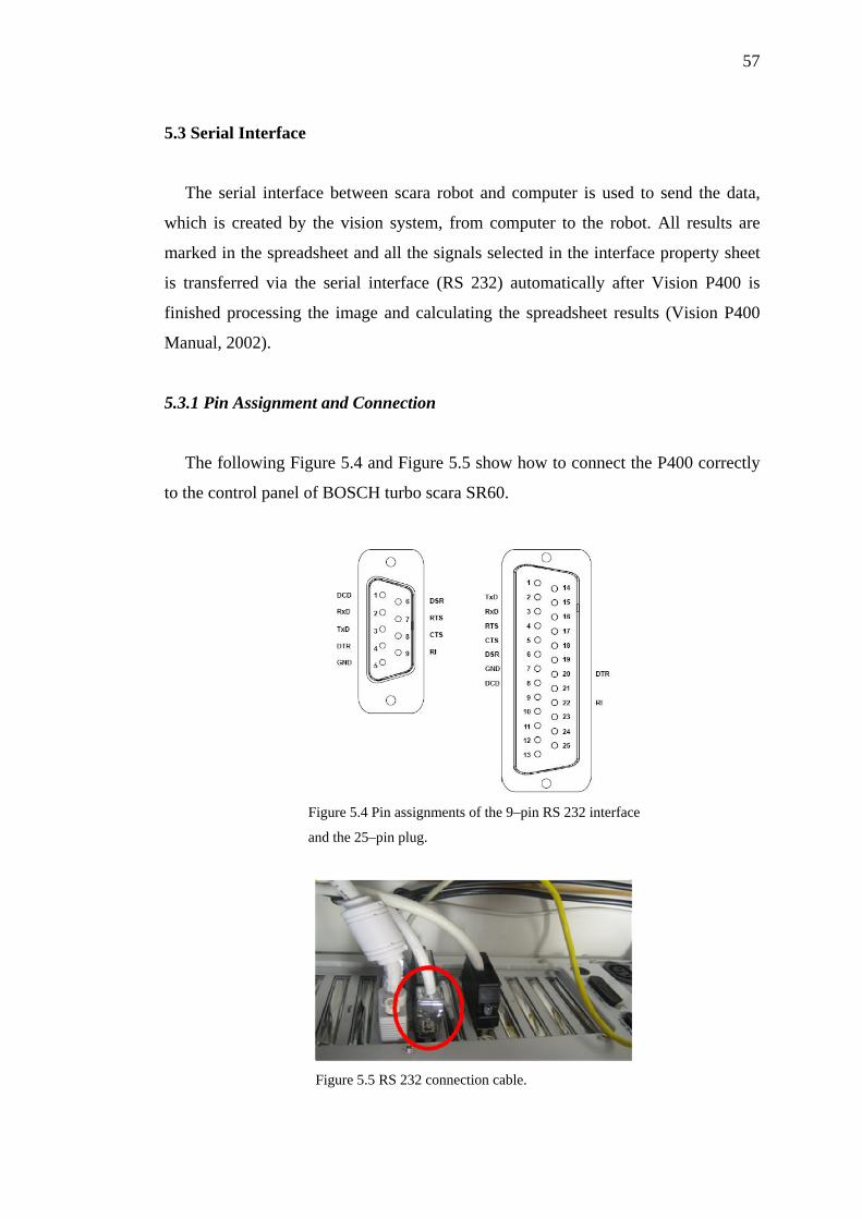
57
5.3 Serial Interface
The serial interface between scara robot and computer is used to send the data,
which is created by the vision system, from computer to the robot. All results are
marked in the spreadsheet and all the signals selected in the interface property sheet
is transferred via the serial interface (RS 232) automatically after Vision P400 is
finished processing the image and calculating the spreadsheet results (Vision P400
Manual, 2002).
5.3.1 Pin Assignment and Connection
The following Figure 5.4 and Figure 5.5 show how to connect the P400 correctly
to the control panel of BOSCH turbo scara SR60.
Figure 5.4 Pin assignments of the 9–pin RS 232 interface
and the 25–pin plug.
Figure 5.5 RS 232 connection cable.
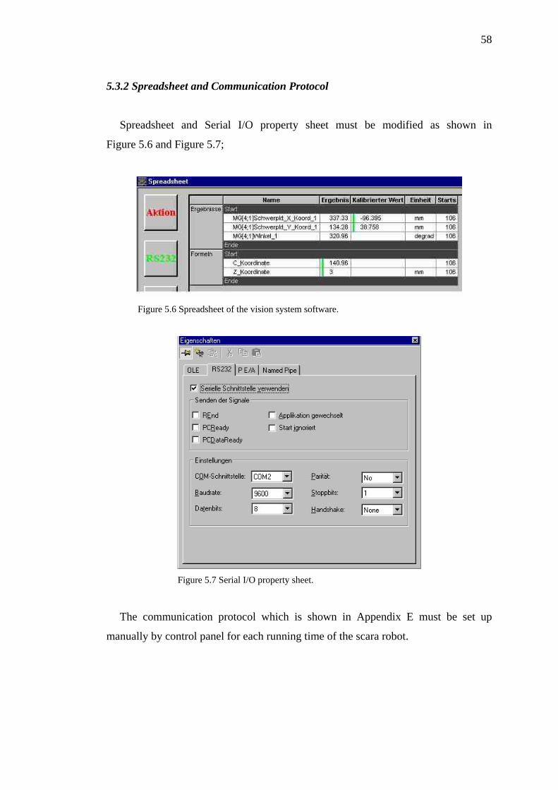
58
5.3.2 Spreadsheet and Communication Protocol
Spreadsheet and Serial I/O property sheet must be modified as shown in
Figure 5.6 and Figure 5.7;
Figure 5.6 Spreadsheet of the vision system software.
Figure 5.7 Serial I/O property sheet.
The communication protocol which is shown in Appendix E must be set up
manually by control panel for each running time of the scara robot.
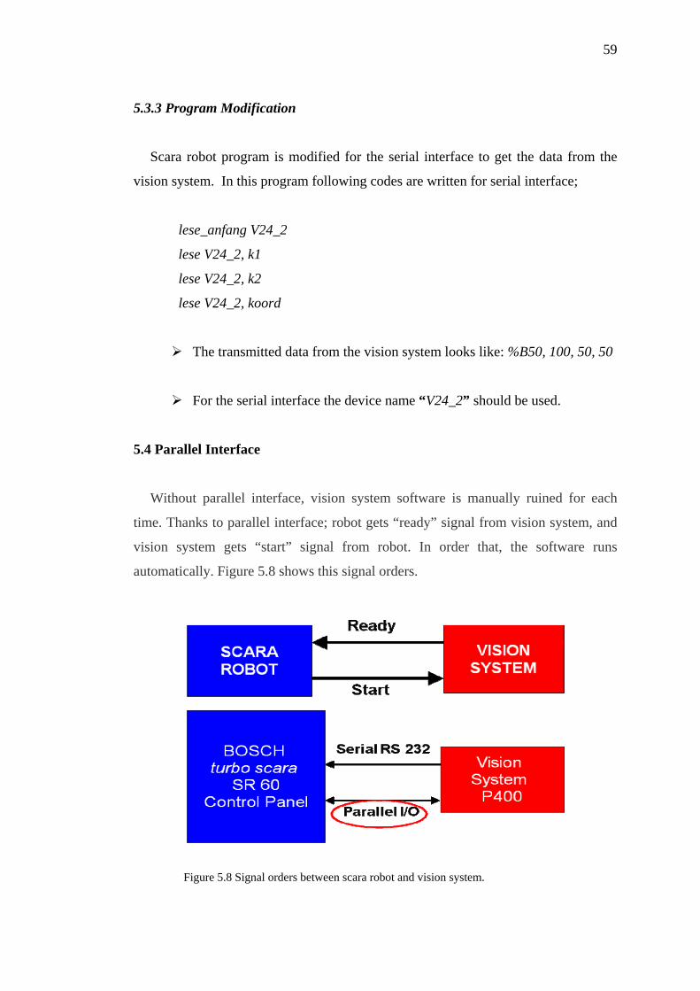
59
5.3.3 Program Modification
Scara robot program is modified for the serial interface to get the data from the
vision system. In this program following codes are written for serial interface;
lese_anfang V24_2
lese V24_2, k1
lese V24_2, k2
lese V24_2, koord
The transmitted data from the vision system looks like: %B50, 100, 50, 50
For the serial interface the device name “V24_2” should be used.
5.4 Parallel Interface
Without parallel interface, vision system software is manually ruined for each
time. Thanks to parallel interface; robot gets “ready” signal from vision system, and
vision system gets “start” signal from robot. In order that, the software runs
automatically. Figure 5.8 shows this signal orders.
Figure 5.8 Signal orders between scara robot and vision system.
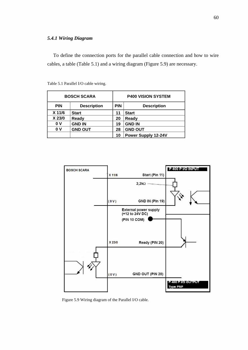
60
5.4.1 Wiring Diagram
To define the connection ports for the parallel cable connection and how to wire
cables, a table (Table 5.1) and a wiring diagram (Figure 5.9) are necessary.
Table 5.1 Parallel I/O cable wiring.
BOSCH SCARA P400 VISION SYSTEM
PIN Description PIN Description X 11/6 Start 11 Start X 23/0 Ready 20 Ready
0 V GND IN 19 GND IN 0 V GND OUT 28 GND OUT
10 Power Supply 12-24V
Figure 5.9 Wiring diagram of the Parallel I/O cable.
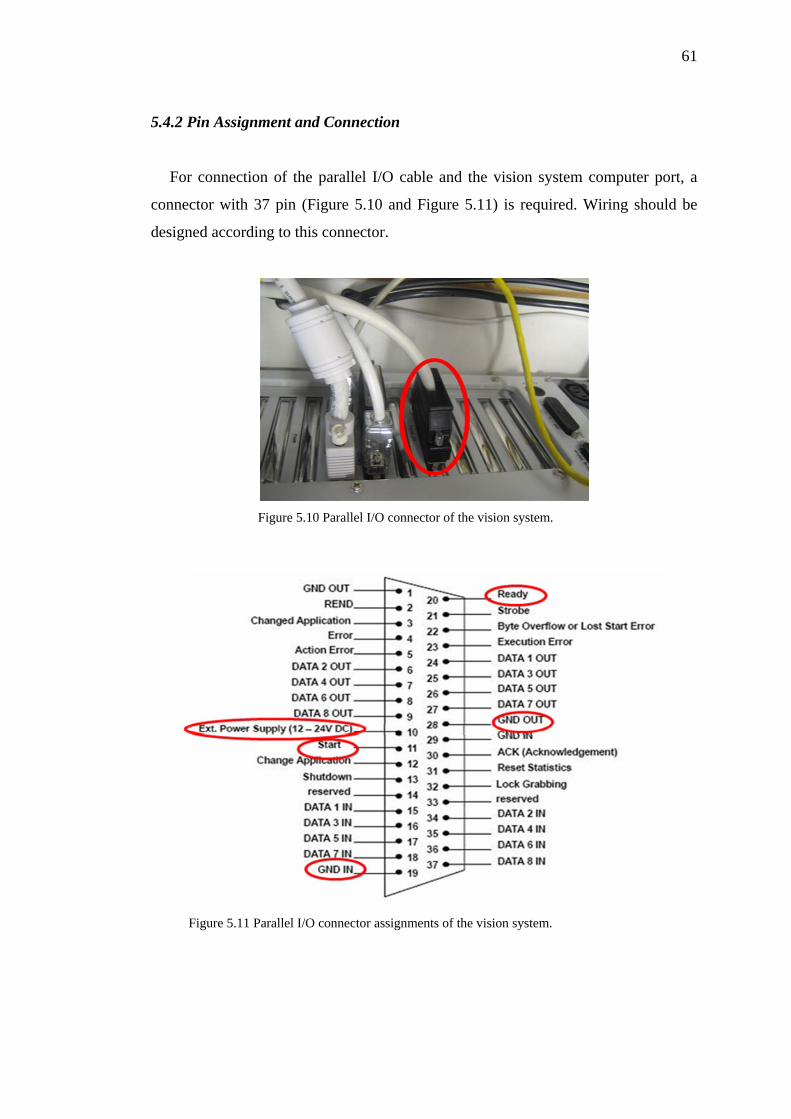
61
5.4.2 Pin Assignment and Connection
For connection of the parallel I/O cable and the vision system computer port, a
connector with 37 pin (Figure 5.10 and Figure 5.11) is required. Wiring should be
designed according to this connector.
Figure 5.10 Parallel I/O connector of the vision system.
Figure 5.11 Parallel I/O connector assignments of the vision system.
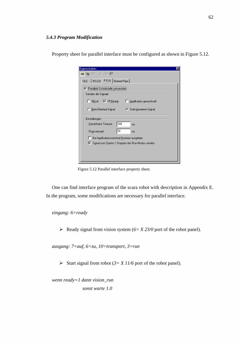
62
5.4.3 Program Modification
Property sheet for parallel interface must be configured as shown in Figure 5.12.
Figure 5.12 Parallel interface property sheet.
One can find interface program of the scara robot with description in Appendix E.
In the program, some modifications are necessary for parallel interface.
eingang: 6=ready
Ready signal from vision system (6= X 23/0 port of the robot panel).
ausgang: 7=auf, 6=zu, 10=transport, 3=run
Start signal from robot (3= X 11/6 port of the robot panel).
wenn ready=1 dann vision_run
sonst warte 1.0
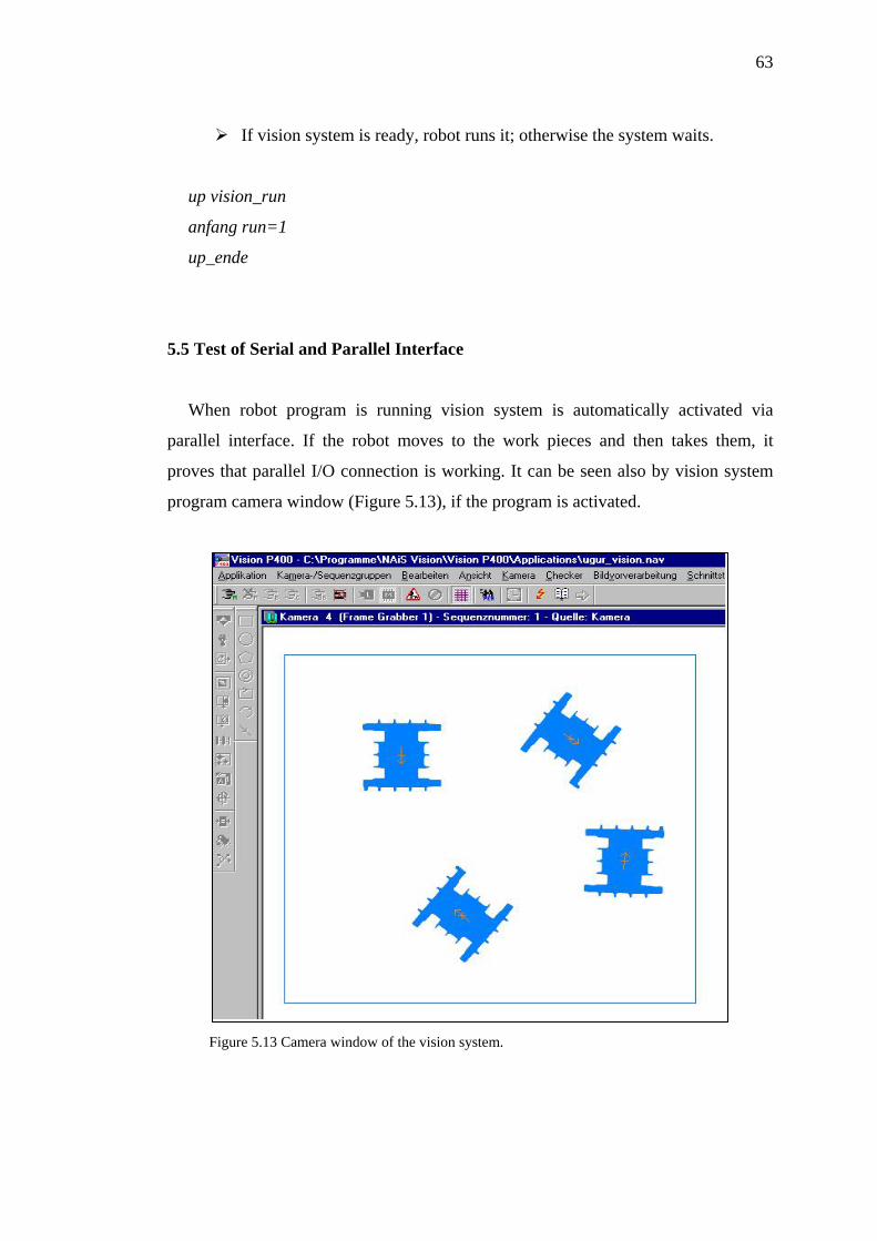
63
If vision system is ready, robot runs it; otherwise the system waits.
n=1
p_ende
.5 Test of Serial and Parallel Interface
by vision system
program camera window (Figure 5.13), if the program is activated.
igure 5.13 Camera window of the vision system.
up vision_run
anfang ru
u
5
When robot program is running vision system is automatically activated via
parallel interface. If the robot moves to the work pieces and then takes them, it
proves that parallel I/O connection is working. It can be seen also
F
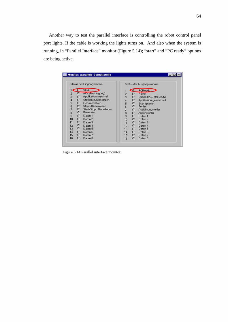
64
cable is working the lights turns on. And also when the system is
nning, in “Parallel Interface” monitor (Figure 5.14); “start” and “PC ready” options
are being active.
Another way to test the parallel interface is controlling the robot control panel
port lights. If the
ru
Figure 5.14 Parallel interface monitor.
CHAPTER SIX
CONCLUSIONS
As a main task of this thesis, a macro-positioning robot for an hexapod is
designed. Prototype of this design is manufactured. For macro-positioning of the
hexapod, standard type robots such as a scara robot can be used instead of designing
a special robot. However, standard robots cannot be optimised as much as a special
design robot. In normal case, designing a robot system costs a lot. On the other hand,
using integrated design method reduces these design costs dramatically. In this
thesis, it was experienced. First of all, integrated modelling, analysing, simulation
and controlling programs with VisualBASIC reduce spending time for a design. For
example, when a problem is observed during an analysis, the model is modified
easily. API capabilities of SolidWorks, CosmosWorks and CosmosMotion programs
were used for developing integrated design programs.
Another important advantage of integrated design is that, possibility of more
successful prototype building. Most of the parameters which are possible to affect a
robotic system can be considered during the design processes with this method. As a
result of this, manufactured prototype was closer to the purposed design. Therefore,
there was no need to manufacture many prototypes such as being done in other
design methods. Selecting of appropriate actuators for the robot was also experienced
in this study. Harmonic Drive servo units were selected as actuators of the robot by
help of the initial model design.
Control systems of the robotic applications are generally sophisticated. Most of
the ready control systems are sold with their own control software. These control
software are expensive and limited for user based modifications. For application
based special designs, such as macro-positioning robot design for an hexapod, they
are not effective. Therefore, in this thesis, specific control programs were developed
by VisualBASIC for controlling of the robot. They were also integrated to the
65
66
simulation programs. Only the required features were added to these developed
programs. Hence, the programs became compact and they can easily be modified.
After finishing all the analyses of the final model, prototype of the macro-
positioning robot was manufactured. Most of the prototype parts except the actuators
were manufactured and then assembled. For manufacturing processes 2D technical
drawings were generated from the solid models of the parts. A payload test was
made. As a result of the test, the prototype was very close to proposed robot design.
The actuators of the robot move smoothly with test loads. Only some small
vibrations were observed during the motions. Vibration problem is planned to be
solved in future studies about the macro-positioning robot. Repeatability of the servo
units was controlled also regarding to micron precision requirement for positioning.
The results about the repeatability are satisfying.
In this thesis, as an additional study, an interface between a scara robot and vision
system was developed. This study took place in robotics and automation labs of
University of Rosenheim in Germany. The purpose of the interface is running a scara
robot and vision system simultaneously. For this reason a parallel interface was
developed and a serial interface, which was already installed, was modified to adapt
the parallel interface. As a result of these modifications and developments, scara
robot sends the data about its working process to the vision system via the parallel
interface. After that, vision system sends the coordinate data of the parts to the robot
via serial interface. The development was tested and controlled. The most important
advantage of this development is that operator of the systems is not running the
vision system program for each cycle of the robot anymore. Systems work
automatically and there is no need for an operator during the cycles of the robot.
REFERENCES
Anaheim Automation Inc. (2005). Stepper motor glossary. Retrieved June 1, 2007,
from http://www.anaheimautomation.com/stepper_motor_glossary.aspx.
Asada, H., & Toumi, K.Y. (1987). Direct-Drive Robots, Theory and Practice.
Cambridge: MIT Press.
Baldor Electric Company (2007). Baldor. Retrieved April 16, 2007, from
http://www.baldor.com.
Barrow, H.G., & Tenenbaum, J.M. (1978). Recovering intrinsic scene characteristics
from images. A. Hanson, & E. Riseman, (Eds.). In Computer Vision Systems (3-
26). New York: Academic Press.
Barrow, H.G., & Tenenbaum, J.M. (1981). Computational vision. Proceedings of the
IEEE, 69 (5), 572-595.
Bok, K., Myung, S., & Han, S. -H. (Eds.). (2000). Lens barrel design based on
distributed knowledge-base. Knowledge intensive computer aided design. Kluwer
Academic Publishers. 255-271.
BOSCH turbo scara SR60 Manual (1999). BOSCH Automation.
Brown, D.C. (1999). Requirements for configurer tests: A position statement. Papers
form the AAAI’99 Workshop on Configuration, Orlando, USA. Retrieved March
21, 2007, from http://www.ifi.uni-klu.ac.at/-alt/aai99/25brown.ps.
Bruyninckx, H., & Schutter, J.D. (2001). Introduction to intelligent robotics.
(7th ed.). Leuven: Katholieke Universiteit Leuven, Department Werktuigkunde.
67
68
Burisch, A., Soetebier, S., Wrege, J. (2005). Design of a parallel hybrid micro-scara
robot for high precision assembly. Institute of Machine Tools and Production
Technology, Technical University of Braunschweig.
Chin, R.T., & Harlow, C.A. (1982). Automated visual inspection: A survey. IEEE
Trans. Pattern Analy. And Mach. Intellig. 4(6), 557-573.
Coyle-Byrne, J., & Klafter, R.D. (1990). Real-Time Zone-Adaptive Control of a
SCARA-Type Robot Arm. IEEE International Robotics and Automation
Conference, 3, 2089–2094.
Custom Solutions Inc. (December 05, 2006). Custom Solutions. Retrieved December
22, 2006, from http://www.csi3.com/PC_Stand.htm.
Dandil, B., Gokbulut, M., & Ata, F. (2004). Doğrusal olmayan yük şartlarındaki
asenkron motorun YSA-PI hız denetimi. Firat Universitesi Fen ve Muhendislik
Bilimleri Dergisi, 16 (1), 39-48.
Degen R., & Slatter R.(2002). Hollow shaft micro servo actuators realized with the
Micro HarmonicDrive, Proceedings of Actuator, Bremen.
DIRA Dansk Robot Forening (2007). Robotdef. Retrieved December 1, 2007, from
http://www.dira.dk/pdf/robotdef.pdf.
Dulger, L.C., Kireci, A., & Topalbekiroglu, M. (2001). AC Servo motorlarının
modellenmesi , simulasyonu ve hareket denetiminde kullanılması. 10. Ulusal
Mak. Teo. Sempozyumu Bil. Kit., 1, 181-189.
Dynatec Automation Products Inc. (2007). Gantry Robot. Retrieved October 2, 2007,
from http://www.dynatecautomation.com.
69
Franke, D.W. (1998). Configuration research and commercial solutions. Special
Issue: Configuration Design, AIEDAM, 12(4), 295–300.
Gough, V.E., & Whitehall, S.G. (1962). Universal Tyre Test Machine. Proceedings
of the 9th International Technical Congress (FISITA), 1, 177.
Han, S.H., Kim, Y.H., Ha, I.J., Lee, S.T., & Park, J.J. (1995). A learning approach to
high precision speed control of servo motors. IEEE, 26 (3), 221-226.
Hansen Motor Corp. (2006). Servo motors. Retrieved May 16, 2007, from
http://www.hansen-motor.com/servo-motors.htm.
Harmonic Drive AG (2006). Precision in Motion Catalogue 2005/2006. In CHA
Hollow Shaft Actuators (256-283).
Hashimoto, H., Yamamoto, H., Yanagisawa, S., & Harashima, F. (1988). Brushless
servo motor control using variable structure approach. IEEE Transactions on
Industry Applications, 24 (1), 160-170.
Huang, T.S., Schreiber, W.F., & Tretiak, O.J. (1971). Image Processing Techniques.
S. Nudelman, & R. Zirkind, (Eds.). In Developments in Electronic Imaging
Techniques II, SPIE Proceedings (32th ed.) (77). Bellingham, WA: Society for
Photo-Optical Instrumentation Engineers.
International Organisation for Standardization (1994). ISO 8373, Manipulating
industrial robots vocabulary. Retrieved June 16, 2007, from http://www.iso.org.
Janome Robotics (2007). Scara robot view. Retrieved August 9, 2007, from
http://www.janomerobotics.de.
70
Kang, C-S., & Han, S.-H. (1997). Parametric design of a car audio based on
configuration design method. Transactions of the Society of CAD/CAM
Engineers, 2(4), 276–285.
Karagülle, H., Sarıgül, S., Kıral, Z., Varol, K., & Malgaca, L. (01 July 2006).
Mikro-konumlandırıcı Robot Tasarımı ve Prototip İmalatı. TÜBİTAK Araştırma
Projesi 1. Dönem Gelişme Raporu, Project No: 104M373.
Karagülle, H., Sarıgül, S., Kıral, Z., Varol, K., & Malgaca, L. (01 January 2007).
Mikro-konumlandırıcı Robot Tasarımı ve Prototip İmalatı. TÜBİTAK Araştırma
Projesi 2. Dönem Gelişme Raporu, Project No: 104M373.
Karagülle, H., Sarıgül, S., Kıral, Z., Malgaca, L, & Akdag, M. (01 July 2007).
Mikro-konumlandırıcı Robot Tasarımı ve Prototip İmalatı. TÜBİTAK Araştırma
Projesi 3. Dönem Gelişme Raporu, Project No: 104M373.
Karagülle, H., Malgaca, L., & Akdag, M. (2007). Robotik sistemlerin bilgisayar
destekli tasarım ve analiz kontrolünün entegrasyonu.Dokuz Eylül Üniversitesi,
Makina Mühendisligi Bölümü, Izmir.
Koo, D-H., Han, S.H., & Lee, S.H. (1998). An object-oriented configuration design
method for paper feeding mechanisms. International Journal of Expert Systems
with Applications, 14(3), 283–289.
Krut, S., Company, O., & Pierrot, F. (2002). Velocity performance indexes for
parallel mechanisms with actuation redundancy. Workshop on fundamental issues
and future research directions for parallel mechanisms and manipulators, Quebec
Ctiy, Canada (October 2-4).
Lin, F.J., & Chiu, S.L. (1998). Adaptive fuzzy sliding-mode control for PM
synchronous servo motor drives. IEE Proceedings - Control theory Applications,
145 (1), 63-72.
71
Lin, F.J., & Wai, R.J. (1998). Hybrid controller using a neural network for a PM
synchronous servo-motor drive. IEE Proc.-Electr. Power Appl., 3, 223-230.
Marr, D., & Ullman, S. (1981). Directional selectivity and its use in early visual
processing. Proceedings of the Royal Society of London, Series B, Biological
Sciences, 211, 151-180.
Mcalinden, L. P., Florida-James, B. O., Chao, K.-M., Norman, P. W., Hills, W.,
& Smith, P. (1998). Information and knowledge sharing for distributed design
agents. In Artificial Intelligence in Design `98, Proceedings of Fifth International
Conference on Artificial Intelligence in Design, Lisbon, Portugal. Kluwer
Academic Publishers. 537-556.
Micos GmbH (2007). Hexapod PAROS (2) view. Retrieved August 9, 2007, from
http://www.micos.ws/Paros.html.
Microdynamic Systems Laboratory, CMU (2007). Scara robots for
precision assembly. Retrieved September 7, 2006, from
http://www.msl.ri.cmu.edu/projects/minifactory/comparisons.php
MSDN (2007). Microsoft Corporation. Retrieved May 19, 2007, from
http://msdn2.microsoft.com/en-us/vbasic/default.aspx.
Myung, S., & Han, S.-H. (2001). Knowledge-based parametric design of mechanical
products based on configuration design method. Expert Systems with
Applications, 21, 99-107.
Nishihara, K., & Poggio, T. (1984). Stereo vision for robotics. R. Paul, & M. Brady,
(Eds.). In Robotics Research, First Int. Symp. (489-505). Cambridge, MA: MIT
Press.
72
Park, H., & Cho, H. (1991). General design conditions for an ideal robotic
manipulator having simple dynamics. The International Journal of Robotics
Research, 10, 21–29.
Physik Instrumente (PI) Company (2006). PI. Retrieved 2006, from www.pi.com.
Poggio, T., & Koch, C. (1985). III-Posed problems in early vision: from
computational theory to analogue networks. Proceedings of the Royal Society of
London, Series B, Biological Sciences, 226, 303-323.
Robot Hall of Fame (2007). The 2006 Inductees: SCARA. Retrieved September 3,
2007, from http://www.robothalloffame.org/06inductees/scara.html.
Robotmatrix (2006). Robot Configuration. Retrieved October 2, 2007, from
http://www.robotmatrix.org/RobotConfiguration.htm.
Sabin, D., & Weigel, R. (1998). Product configuration frameworks: a survey, in
special issue on configuration. IEEE Intelligent Systems, 13(4), 42-49.
Sahbaz, H. (2007). PC-Based Control of Hexapod, Master Thesis. The Graduate
School of Natural and applied Sciences, Dokuz Eylul University.
Sandler, B.Z. (1999). Robotics: Designing the Mechanisms for Automated Machinery
(2nd ed.). San Diego: Academic Press.
SolidWorks Corporation (2007). SolidWorks. Retrieved March 18, 2007, from
www.solidworks.com.
Sortimat Technology (2006). Feeding system view.. Retrieved June 1, 2007, from
http://www.sortimat.com.
73
Stewart, D. (1965). A Platform with Six Degrees of Freedom. Proceedings of the
Institution of Mechanical Engineers, 180, 371-386.
Tanev, T.K. (2000). Kinematics of a hybrid (parallel-serial) robot manipulator.
Mechanism and Machine Theory, 35, 1183-1196.
Toumi, K.Y., & Asada, H. (1987). The design of open loop manipulator arms with
decoupled and configuration-invariant inertia tensors. ASME Journal of Dynamic
Systems, Measurement, and Control, 109, 268–275.
Tsai, L.W. (1999). Robot Analysis (The Mechanics of Serial and Parallel
Manipulators). New York: John Wiley & Sons Inc.
Tzou, Y.Y., Wu, H.J. (1990). Multimicroprocessor-based robust control of an AC
induction servo motor. IEEE Transactions on Industry Applications, 26 (3),
441-449.
URS (2007). Universal Robot Systems GMBH & CO.KG. Retrieved 2007, from
www.medicalrobots.com.
Verroust, A., Schonek, F., & Roller, D. (1992). Rule-oriented method for
parameterized computer-aided design. Computer Aided Design, 24(10), 531–540.
Vision P400 Manual (2002). Matsushita Electric Works (Europe) AG. Retrieved
September 2, 2007.
Wikipedia (2007). Robot. Retrieved 2007, from http://en.wikipedia.org/wiki/Robot.
Ximei, Z., & Qingding, G. (2005). H∞ robust control based on international model
theory for linear permanent magnet synchronous motor. Proceedings of the Eighth
International Conference on Electrical Machines and Systems (ICEMS 2005), 2,
1613-1616.
74
Yamamoto, K., & Shinohara, K. (1996). Comparison between space vector
modulation and subharmonic methods for current harmonics of DSP - based
permanent - magnet AC servo motor drive system. IEE Proc.-Electr. Power Appl.,
143 (2), 151-156.
Yang, D.C.H., & Tzeng, S., (1986). Simplification and linearization of manipulator
dynamics by the design of inertia distribution. The International Journal of
Robotics Research, 5(3), 120–128.
Yu, B. (1996). A virtual configuration workbench for product development. PhD
Thesis, Department of Design, Manufacture and Engineering Management,
University of Strathclyde, UK.
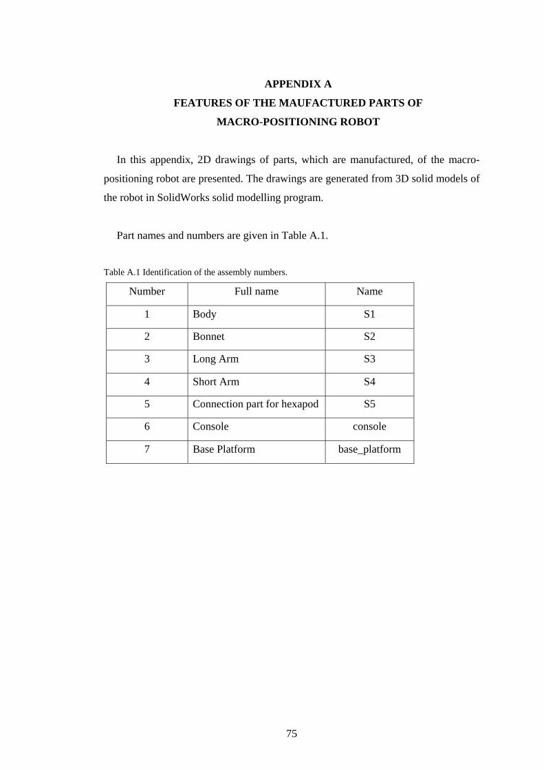
APPENDIX A
FEATURES OF THE MAUFACTURED PARTS OF
MACRO-POSITIONING ROBOT
In this appendix, 2D drawings of parts, which are manufactured, of the macro-
positioning robot are presented. The drawings are generated from 3D solid models of
the robot in SolidWorks solid modelling program.
Part names and numbers are given in Table A.1.
Table A.1 Identification of the assembly numbers.
Number Full name Name
1 Body S1
2 Bonnet S2
3 Long Arm S3
4 Short Arm S4
5 Connection part for hexapod S5
6 Console console
7 Base Platform base_platform
75
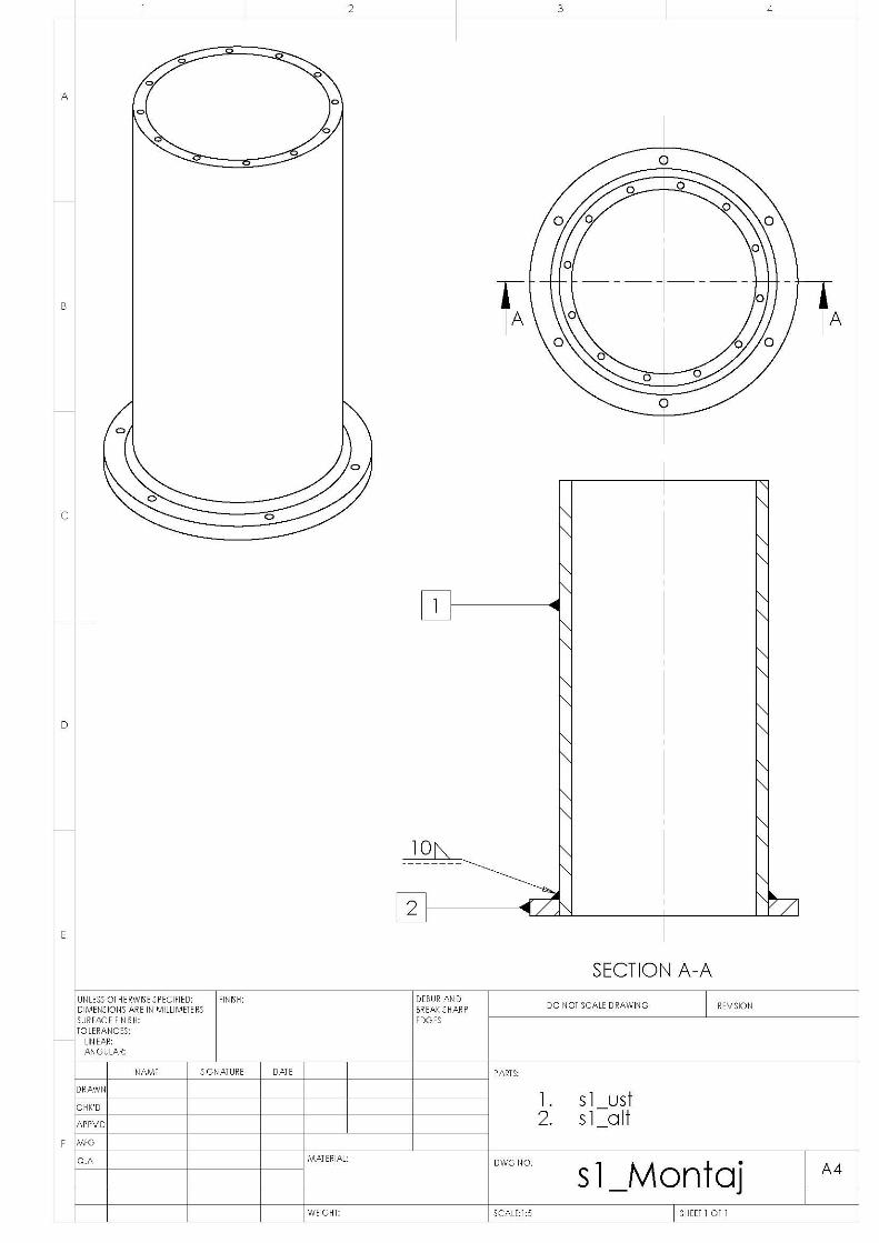
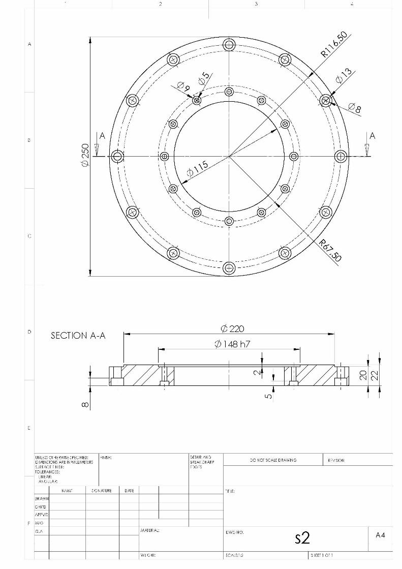
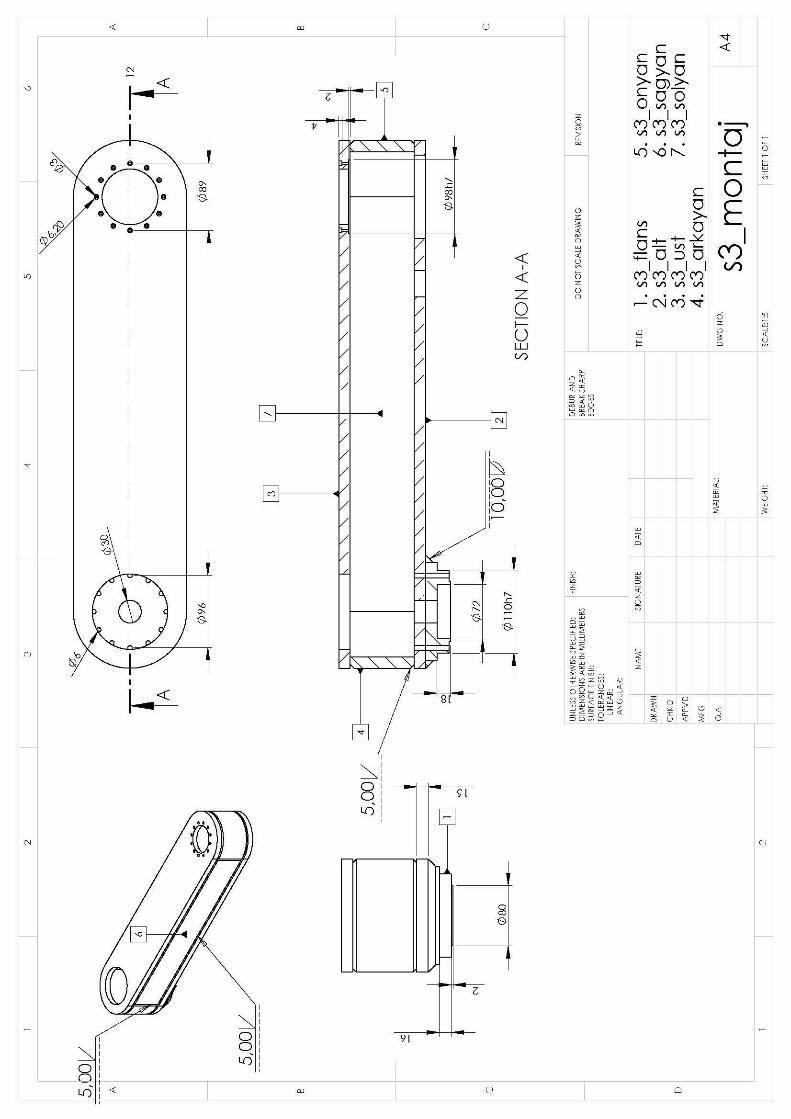
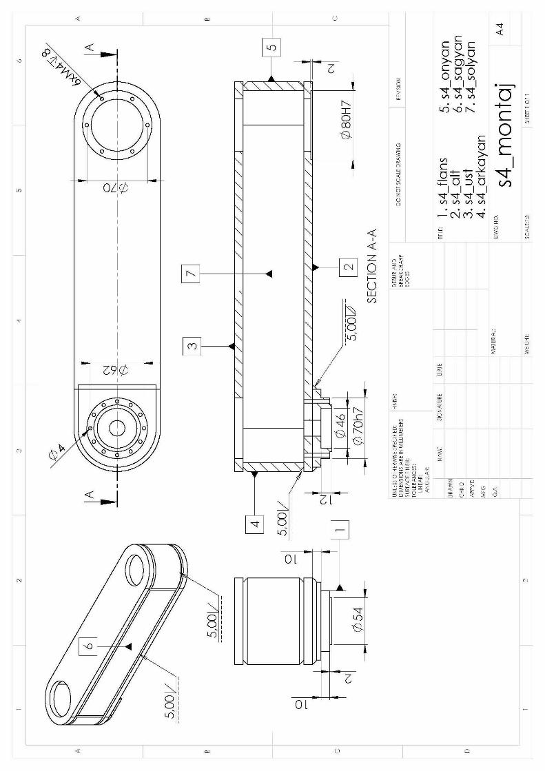
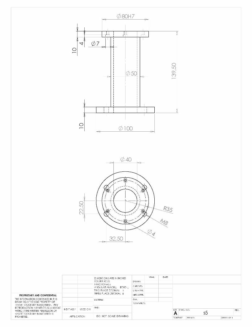
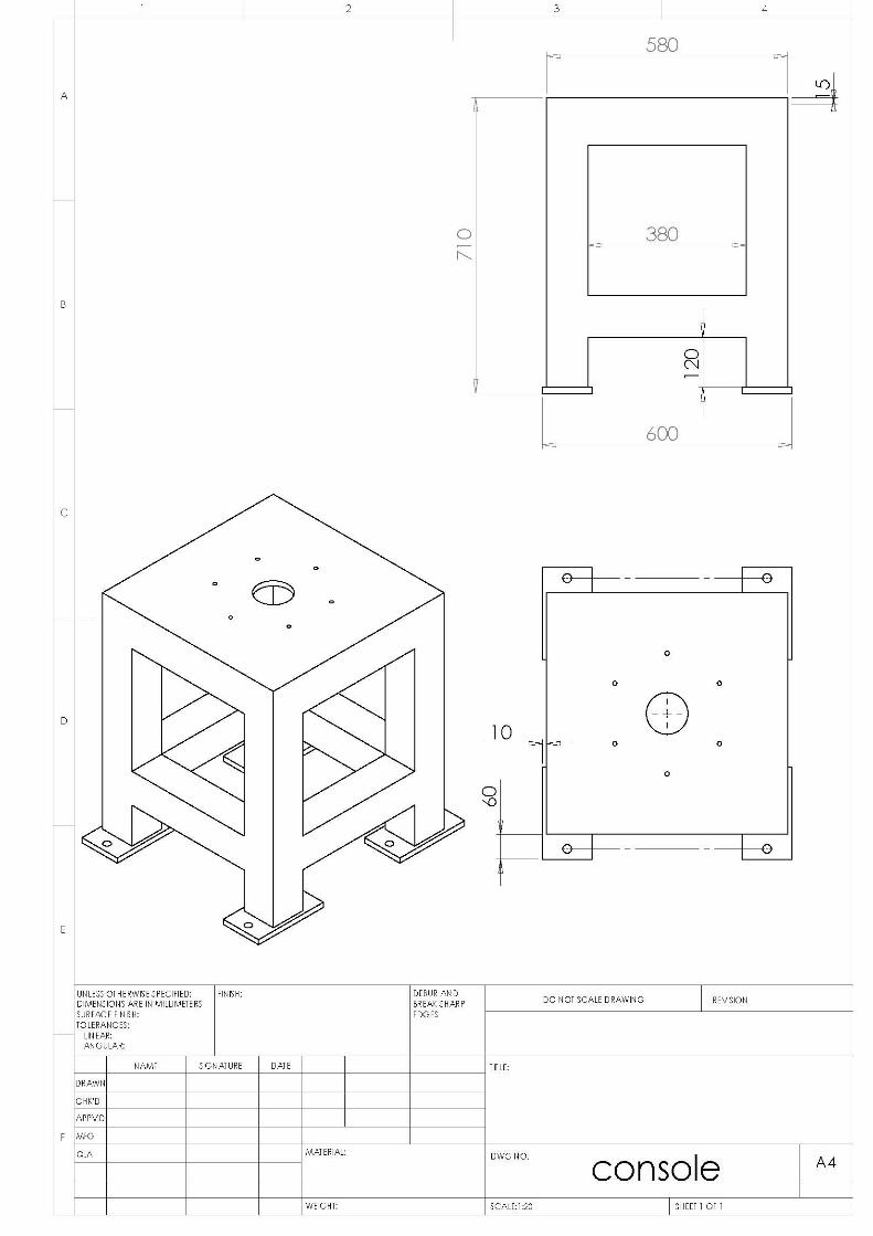
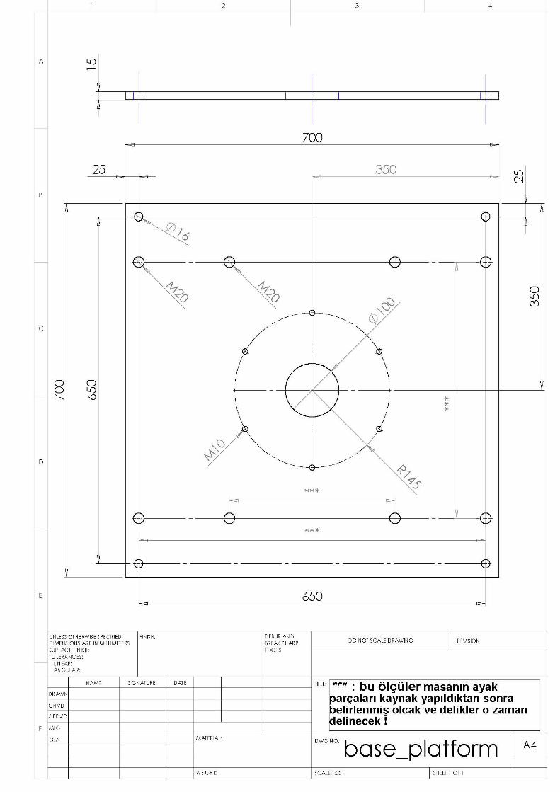
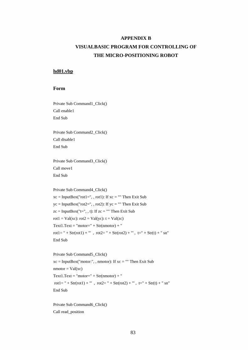
APPENDIX B
VISUALBASIC PROGRAM FOR CONTROLLING OF
THE MICRO-POSITIONING ROBOT
hd01.vbp
Form
Private Sub Command1_Click()
Call enable1
End Sub
Private Sub Command2_Click()
Call disable1
End Sub
Private Sub Command3_Click()
Call move1
End Sub
Private Sub Command4_Click()
xc = InputBox("rot1=", , rot1): If xc = "" Then Exit Sub
yc = InputBox("rot2=", , rot2): If yc = "" Then Exit Sub
zc = InputBox("t=", , t): If zc = "" Then Exit Sub
rot1 = Val(xc): rot2 = Val(yc): t = Val(zc)
Text1.Text = "motor=" + Str(nmotor) + "
rot1= " + Str(rot1) + "' , rot2= " + Str(rot2) + "' , t=" + Str(t) + " sn"
End Sub
Private Sub Command5_Click()
xc = InputBox("motor:", , nmotor): If xc = "" Then Exit Sub
nmotor = Val(xc)
Text1.Text = "motor=" + Str(nmotor) + "
rot1= " + Str(rot1) + "' , rot2= " + Str(rot2) + "' , t=" + Str(t) + " sn"
End Sub
Private Sub Command6_Click()
Call read_position
83
84
End Sub
Private Sub Command7_Click()
Call move_reverse
End Sub
Private Sub Form_Activate()
Call enable1
End Sub
Private Sub Form_Load()
WindowState = 2
nmotor = 12: rot1 = 90: rot2 = -90: t = 5
Form1.AutoRedraw = True
Text1.Text = "motor=" + Str(nmotor) + "
rot1= " + Str(rot1) + "' , rot2= " + Str(rot2) + "' , t=" + Str(t) + " sn"
Timer1.Interval = 1000 ' Set Timer interval.
Command1.Caption = "Enable"
Command2.Caption = "Disable"
Command3.Caption = "move"
Command4.Caption = "rot, time"
Command5.Caption = "motor"
Command6.Caption = "read position"
Command7.Caption = "reverse"
End Sub
Private Sub Form_Terminate()
Call disable1
End Sub
Private Sub Timer1_Timer()
Label1.Caption = Time ' Update time display.
End Sub
85
Module – module.bas
'Install baldor workbench
' Project>Components>Mint Controls Build 5523
Public rot1 As Double, rot2 As Double, t As Double
Public nmotor As Integer
Sub enable1()
Form1.MintController1.SetSerialControllerLink 1, 2, 1, 57600, True
Form1.MintController1.DriveEnable(0) = True
Form1.MintController1.SetSerialControllerLink 1, 2, 7, 57600, True
Form1.MintController1.DriveEnable(0) = True
End Sub
Sub disable1()
Form1.MintController1.SetSerialControllerLink 1, 2, 1, 57600, True
Form1.MintController1.DriveEnable(0) = False
Form1.MintController1.SetSerialControllerLink 1, 2, 7, 57600, True
Form1.MintController1.DriveEnable(0) = False
End Sub
Sub move1()
If nmotor = 1 Then Call Motor1
If nmotor = 2 Then Call Motor2
If nmotor = 12 Then Call Motor12
End Sub
Sub Motor1()
speed1 = 10 * rot1 / t: speed1a = Abs(speed1): acc1 = speed1a * 50
If speed1a > 5000 Then MsgBox "Failure! : Speed is out of range"
Form1.MintController1.SetSerialControllerLink 1, 2, 1, 57600, True
Form1.MintController1.ScaleFactor(0) = 9102
Form1.MintController1.TimeScale(0) = 10000
Form1.MintController1.Accel(0) = acc1
Form1.MintController1.Decel(0) = acc1
Form1.MintController1.Speed(0) = speed1a
Form1.MintController1.MoveR(0) = rot1
Form1.MintController1.DoGo1 (0)
86
End Sub
Sub Motor2()
speed2 = 10 * rot2 / t: speed2a = Abs(speed2): acc2 = speed2a * 50
If speed2a > 3800 Then MsgBox "Failure! : Speed is out of range"
Form1.MintController1.SetSerialControllerLink 1, 2, 7, 57600, True
Form1.MintController1.ScaleFactor(0) = 9102
Form1.MintController1.TimeScale(0) = 10000
Form1.MintController1.Accel(0) = acc2
Form1.MintController1.Decel(0) = acc2
Form1.MintController1.Speed(0) = speed2a
Form1.MintController1.MoveR(0) = rot2
Form1.MintController1.DoGo1 (0)
End Sub
Sub Motor12()
speed1 = 10 * rot1 / t: speed1a = Abs(speed1): acc1 = speed1a * 50
If speed1a > 5000 Then MsgBox "Failure! : Speed is out of range"
Form1.MintController1.SetSerialControllerLink 1, 2, 1, 57600, True
Form1.MintController1.ScaleFactor(0) = 9102
Form1.MintController1.TimeScale(0) = 10000
Form1.MintController1.Accel(0) = acc1
Form1.MintController1.Decel(0) = acc1
Form1.MintController1.Speed(0) = speed1a
Form1.MintController1.MoveR(0) = rot1
Form1.MintController1.DoGo1 (0)
speed2 = 10 * rot2 / t: speed2a = Abs(speed2): acc2 = speed2a * 50
If speed2a > 3800 Then MsgBox "Failure! : Speed is out of range"
Form1.MintController1.SetSerialControllerLink 1, 2, 7, 57600, True
Form1.MintController1.ScaleFactor(0) = 9102
Form1.MintController1.TimeScale(0) = 10000
Form1.MintController1.Accel(0) = acc2
Form1.MintController1.Decel(0) = acc2
Form1.MintController1.Speed(0) = speed2a
Form1.MintController1.MoveR(0) = rot2
Form1.MintController1.DoGo1 (0)
End Sub
87
Sub read_position()
Form1.MintController1.SetSerialControllerLink 1, 2, 1, 57600, True
n1 = Form1.MintController1.Pos(0)
Form1.MintController1.SetSerialControllerLink 1, 2, 7, 57600, True
n2 = Form1.MintController1.Pos(0)
Form1.Print "rot1'=", n1, "rot2'=", n2
End Sub
Sub move_reverse()
If nmotor = 1 Then rot1 = -rot1: Call Motor1
If nmotor = 2 Then rot2 = -rot2: Call Motor2
If nmotor = 12 Then rot1 = -rot1: rot2 = -rot2: Call Motor12
End Sub
'Note:
'Form1.MintController1.ScaleFactor(0) = 9102
'Form1.MintController1.TimeScale(0) = 10000
APPENDIX C
VISUALBASIC PROGRAM FOR MODELLING OF
THE MICRO-POSITIONING ROBOT
Model.vbp
Form
Private Sub Command1_Click()
Call insparts
End Sub
Private Sub Command2_Click()
Call locparts
End Sub
Private Sub Command3_Click()
Call assem1
End Sub
Private Sub Command4_Click()
Call forward1
End Sub
Private Sub Form_Load()
fl0 = "d:\scara\v1\"
pi = 4 * Atn(1): WindowState = 2: AutoRedraw = True
Command1.Caption = "insert parts"
Command2.Caption = "locate"
Command3.Caption = "assembly"
Command4.Caption = "forward1"
End Sub
Module – model_assem.bas
Public fl0 As String, pi As Double
Public n1 As Long, n2 As Long, fim1 As Double, fim2 As Double
88
89
Public fla As String, elem As Object, nft As Long
Public swapp As Object, asmbl As Object, comp As String, vtr(15) As Double
Public thx As Double, thy As Double, thz As Double
Public xt As Double, yt As Double, zt As Double, cfix As String
Sub inp1()
fla = "scara1"
fim1 = 0: fim2 = -130
End Sub
Sub locparts()
xc = InputBox("Continue", , "y"): If xc <> "y" Then Exit Sub
Set swapp = GetObject(, "sldworks.application"): Form1.Cls
Set asmbl = swapp.ActiveDoc: Call inp1
comp = "p0-1@" + fla: cfix = "unfix": thy = 90: GoSub 60: cfix = "fix": GoSub 60
comp = "p1-1@" + fla: thy = -fim1: GoSub 60
comp = "p2-1@" + fla: thy = -fim2: GoSub 60
comp = "p3-1@" + fla: xt = 400 / 1000: GoSub 60
asmbl.ViewZoomtofit2: bs = asmbl.EditRebuild3
Exit Sub
60 Call locate1: Return
End Sub
Sub forward1()
expth1 = "": expth2 = "": td = 0: Form1.Cls: kon1 = 1
Open fl0 + "encoder.txt" For Input As 1: Input #1, th1e, th2e: Close #1
Open fl0 + "inp_forward.txt" For Input As 1: Input #1, dt
t = 10 * dt: th1 = th1e: th2 = th2e: GoSub 30: th1 = 0: th2 = 0: GoSub 30: t1 = 2 * t
10 Input #1, t: If t = -1 Then GoTo 20
Input #1, th1, th2
th1e = th1e + th1: th2e = th2e + th2
GoSub 30: GoTo 10
20 Close #1: ns1 = CInt(t1 / dt): ns = CInt(td / dt)
Form1.Print th1e, th2e
'----
Set cmaddin = GetObject(, "cmotionswapi.cmotionswaddin")
Set ms = cmaddin.ActiveAssembly.Mechanism
ms.DeleteSimulation
expa = expth1: jc = "Revolute": GoSub 40
expa = expth2: jc = "Revolute2": GoSub 40
90
expa = "0": jc = "Revolute3": GoSub 40
Call ms.Simulate(td, ns)
ms.Simulation.MinFrame = ns1: ms.Simulation.MaxFrame = ns
Exit Sub
30 Form1.Print t, th1, th2
expth1 = expth1 + "+STEP(TIME," + Str(td) + ",0," + Str(td + t) + "," + Str(-th1) + "D)"
expth2 = expth2 + "+STEP(TIME," + Str(td) + ",0," + Str(td + t) + "," + Str(-th2) + "D)"
td = td + t
Return
'------
40 Call ms.GetElementByName(jc, elem): elem.Motions.RotateZ.MotionType = 3
If expa = "0" Then Call elem.Motions.RotateZ.Function.SetConstant(0): Return
Call elem.Motions.RotateZ.Function.SetExpression(expa)
Return
End Sub
Sub assem1()
xc = InputBox("Continue", , "y"): If xc <> "y" Then Exit Sub
Set swapp = GetObject(, "sldworks.application"): Form1.Cls
Set asmbl = swapp.ActiveDoc: Call inp1
b1c = "p1_plane1@p1-1@" + fla + "/p1_motor1rotor-1@p1"
b2c = "p0_plane1@p0-1@" + fla + "/p0_motor1govde-1@p0": GoSub 40
b1c = "p2_plane1@p2-1@" + fla + "/p2_motor2rotor-1@p2"
b2c = "p1_plane2@p1-1@" + fla + "/p1_motor2govde-1@p1": GoSub 40
b1c = "p3_plane1@p3-1@" + fla + "/p3_hexapod-1@p3"
b2c = "p2_plane2@p2-1@" + fla + "/p2_kol-1@p2": GoSub 40
b1c = "p1_axis1@p1-1@" + fla + "/p1_motor1rotor-1@p1"
b2c = "p0_axis1@p0-1@" + fla + "/p0_motor1govde-1@p0": n1 = 1: GoSub 50
b1c = "p2_axis1@p2-1@" + fla + "/p2_motor2rotor-1@p2"
b2c = "p1_axis2@p1-1@" + fla + "/p1_motor2govde-1@p1": n1 = 0: GoSub 50
b1c = "p3_plane1@p3-1@" + fla
b2c = "p2_plane2@p2-1@" + fla + "/p2_kol-1@p2": n1 = 1: GoSub 40
91
b1c = "p3_axis1@p3-1@" + fla
b2c = "p2_axis2@p2-1@" + fla + "/p2_kol-1@p2": n1 = 0: GoSub 50
Exit Sub
40 bs1 = asmbl.Extension.SelectByID2(b1c, "PLANE", 0, 0, 0, True, 1, Nothing, 0)
bs2 = asmbl.Extension.SelectByID2(b2c, "PLANE", 0, 0, 0, True, 1, Nothing, 0)
Call asmbl.AddMate(0, 1, False, 0, 0): asmbl.ClearSelection2 True
Form1.Print b1c, bs1, b2c, bs2: Return
50 bs1 = asmbl.Extension.SelectByID2(b1c, "AXIS", 0, 0, 0, True, 1, Nothing, 0)
bs2 = asmbl.Extension.SelectByID2(b2c, "AXIS", 0, 0, 0, True, 1, Nothing, 0)
Call asmbl.AddMate(0, n1, False, 0, 0): asmbl.ClearSelection2 True
Form1.Print b1c, bs1, b2c, bs2: Return
End Sub
Sub insparts()
xc = InputBox("Continue", , "y"): If xc <> "y" Then Exit Sub
Set swapp = GetObject(, "sldworks.application"): Form1.Cls
Set asmbl = swapp.NewDocument("C:\Program
Files\SolidWorks\data\templates\Assembly.asmdot", 0, 0#, 0#)
Set asmbl = swapp.ActiveDoc: nft = 2
fl = "p0.SLDASM": GoSub 50
fl = "p1.SLDASM": GoSub 50
fl = "p2.SLDASM": GoSub 50
fl = "p3.SLDPRT": n1 = 1: GoSub 50
asmbl.ViewZoomtofit2: bs = asmbl.EditRebuild3
Exit Sub
50 Form1.Print fl0 + fl
Set Part = swapp.OpenDoc6(fl0 + fl, nft, 0, "", n1, n1)
asmbl.AddComponent fl0 + fl, 0, 0, 0
Set Part = swapp.ActivateDoc2(fl, False, nft): Set Part = Nothing
swapp.CloseDoc fl: Return
End Sub
Sub locate1()
bs = asmbl.Extension.SelectByID2(comp, "COMPONENT", 0, 0, 0, False, 0, Nothing, 0)
Set swcomp = asmbl.SelectionManager.GetSelectedObjectsComponent3(1, 0)
92
Form1.Print swcomp.Name, bs
If cfix = "fix" Then asmbl.FixComponent: cfix = "": Exit Sub
If cfix = "unfix" Then cfix = "": asmbl.UnfixComponent
cx = Cos(thx * pi / 180): sx = Sin(thx * pi / 180)
cy = Cos(thy * pi / 180): sy = Sin(thy * pi / 180)
cz = Cos(thz * pi / 180): sz = Sin(thz * pi / 180)
vtr(0) = cy * cz: vtr(1) = -cy * sz: vtr(2) = sy
vtr(3) = sx * sy * cz + cx * sz: vtr(4) = -sx * sy * sz + cx * cz: vtr(5) = -sx * cy
vtr(6) = -cx * sy * cz + sx * sz: vtr(7) = cx * sy * sz + sx * cz: vtr(8) = cx * cy
vtr(9) = xt: vtr(10) = yt: vtr(11) = zt
vtr(12) = 1: vtr(13) = 0: vtr(14) = 0: vtr(15) = 0
xt = 0: yt = 0: zt = 0: thx = 0: thy = 0: thz = 0: cfix = ""
Set trans1 = swapp.GetMathUtility.CreateTransform((vtr))
swcomp.Transform2 = trans1: asmbl.ClearSelection2 (All)
End Sub
APPENDIX D
VISUALBASIC PROGRAM FOR SIMULATION AND FORWARD
KINEMATIC ANALYSIS OF THE MICRO-POSITIONING ROBOT
Motion.vbp
Form
Private Sub Command1_Click()
Call init_move
End Sub
Private Sub Command2_Click()
Call forward1
End Sub
Private Sub Command3_Click()
Call move_f1
End Sub
Private Sub Command4_Click()
Call reset1
End Sub
Private Sub Command5_Click()
xc = InputBox("Axis"): If xc = "" Then Exit Sub
naxis = Val(xc): Text1.Text = Str(naxis) + "," + Str(rot0)
End Sub
Private Sub Command6_Click()
xc = InputBox("rot0"): If xc = "" Then Exit Sub
rot0 = Val(xc): Text1.Text = Str(naxis) + "," + Str(rot0)
End Sub
Private Sub Command7_Click()
If kmint = 1 Then Call read_position
End Sub
93
94
Private Sub Command8_Click()
Call move_a
End Sub
Private Sub Form_Activate()
If kmint = 1 Then Call enable
End Sub
Private Sub Form_Click()
Form1.Cls
End Sub
Private Sub Form_Load()
fl0 = "d:\scara\v1\": kmint = 1
naxis = 1: rot0 = 5: w0 = 0.5 / 10
Text1.Text = Str(naxis) + "," + Str(rot0)
WindowState = 2: AutoRedraw = True
Command1.Caption = "init_move"
Command2.Caption = "forward1"
Command3.Caption = "move_f1"
Command4.Caption = "reset1"
Command5.Caption = "axis"
Command6.Caption = "rot"
Command7.Caption = "read"
Command8.Caption = "move-a"
End Sub
Private Sub Form_Terminate()
If kmint = 1 Then Call disable
End Sub
95
Module 1 – motion.bas
Public counter As Integer
Public fl0 As String, elem As Object, kon1 As Integer, w0 As Double
Public th1e As Double, th2e As Double, rot1 As Double, rot2 As Double
Declare Sub Sleep Lib "kernel32" (ByVal dwmilliseconds As Long)
Dim tma(20) As Double, rot1a(20) As Double, rot2a(20) As Double, na As Integer
Sub move_f1()
If kon1 = 0 Then Exit Sub
xc = InputBox("Continue", , "yes"): If xc = "" Then Exit Sub
Form1.Print
Form1.Print Time$
For n = 3 To na
DoEvents
rot1 = rot1a(n): rot2 = rot2a(n): tm = tma(n)
If rot1 = 0 And rot2 = 0 Then: Form1.Print tm: Sleep tm * 1000: GoTo 10
Call move_motors
10 Next n
Form1.Print Time$
Open fl0 + "encoder.txt" For Output As 1: Print #1, Str(th1e) + "," + Str(th2e): Close #1
End Sub
Sub init_move()
xc = InputBox("th1,th2"): If xc = "" Then Exit Sub
For n = 1 To Len(xc)
If Mid(xc, n, 1) = "," Then GoTo 10
Next n
10 xc1 = Mid(xc, 1, n - 1): rot1 = Val(xc1): xc2 = Mid(xc, n + 1): rot2 = Val(xc2)
rmax = Abs(rot1): If rmax < Abs(rot2) Then rmax = Abs(rot2)
tm = Abs(rmax) * w0: Call move_motors
Open fl0 + "encoder.txt" For Output As 1: Print #1, Str(rot1) + "," + Str(rot2): Close #1
End Sub
Sub forward1()
expth1 = "": expth2 = "": td = 0: Form1.Cls: If kon1 = 0 Then kon1 = 1
Open fl0 + "encoder.txt" For Input As 1: Input #1, th1e, th2e: Close #1
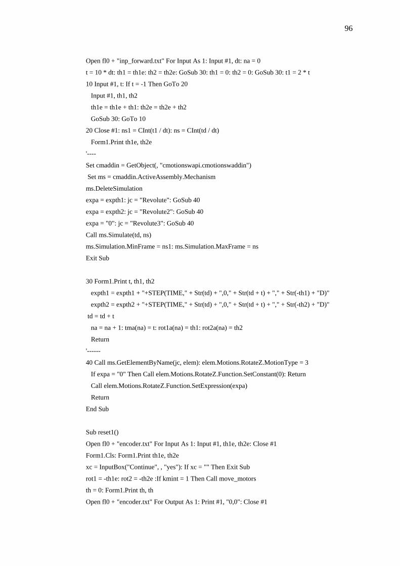
96
Open fl0 + "inp_forward.txt" For Input As 1: Input #1, dt: na = 0
t = 10 * dt: th1 = th1e: th2 = th2e: GoSub 30: th1 = 0: th2 = 0: GoSub 30: t1 = 2 * t
10 Input #1, t: If t = -1 Then GoTo 20
Input #1, th1, th2
th1e = th1e + th1: th2e = th2e + th2
GoSub 30: GoTo 10
20 Close #1: ns1 = CInt(t1 / dt): ns = CInt(td / dt)
Form1.Print th1e, th2e
'----
Set cmaddin = GetObject(, "cmotionswapi.cmotionswaddin")
Set ms = cmaddin.ActiveAssembly.Mechanism
ms.DeleteSimulation
expa = expth1: jc = "Revolute": GoSub 40
expa = expth2: jc = "Revolute2": GoSub 40
expa = "0": jc = "Revolute3": GoSub 40
Call ms.Simulate(td, ns)
ms.Simulation.MinFrame = ns1: ms.Simulation.MaxFrame = ns
Exit Sub
30 Form1.Print t, th1, th2
expth1 = expth1 + "+STEP(TIME," + Str(td) + ",0," + Str(td + t) + "," + Str(-th1) + "D)"
expth2 = expth2 + "+STEP(TIME," + Str(td) + ",0," + Str(td + t) + "," + Str(-th2) + "D)"
td = td + t
na = na + 1: tma(na) = t: rot1a(na) = th1: rot2a(na) = th2
Return
'------
40 Call ms.GetElementByName(jc, elem): elem.Motions.RotateZ.MotionType = 3
If expa = "0" Then Call elem.Motions.RotateZ.Function.SetConstant(0): Return
Call elem.Motions.RotateZ.Function.SetExpression(expa)
Return
End Sub
Sub reset1()
Open fl0 + "encoder.txt" For Input As 1: Input #1, th1e, th2e: Close #1
Form1.Cls: Form1.Print th1e, th2e
xc = InputBox("Continue", , "yes"): If xc = "" Then Exit Sub
rot1 = -th1e: rot2 = -th2e :If kmint = 1 Then Call move_motors
th = 0: Form1.Print th, th
Open fl0 + "encoder.txt" For Output As 1: Print #1, "0,0": Close #1
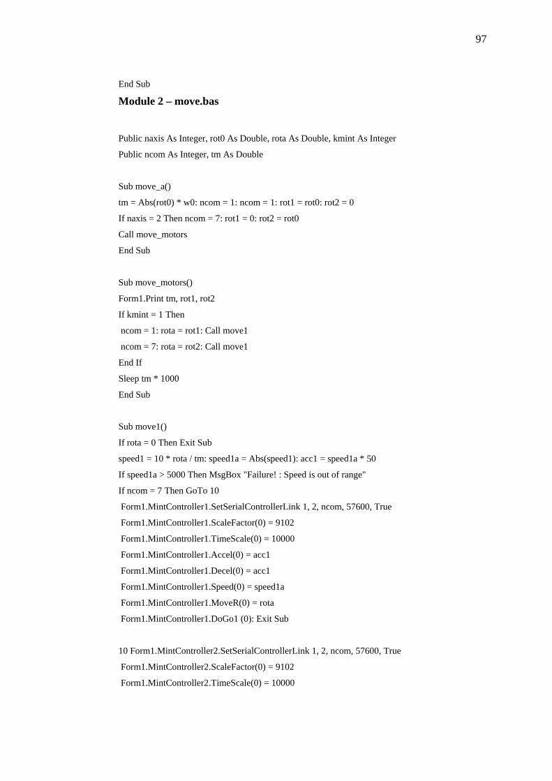
97
End Sub
Module 2 – move.bas
Public naxis As Integer, rot0 As Double, rota As Double, kmint As Integer
Public ncom As Integer, tm As Double
Sub move_a()
tm = Abs(rot0) * w0: ncom = 1: ncom = 1: rot1 = rot0: rot2 = 0
If naxis = 2 Then ncom = 7: rot1 = 0: rot2 = rot0
Call move_motors
End Sub
Sub move_motors()
Form1.Print tm, rot1, rot2
If kmint = 1 Then
ncom = 1: rota = rot1: Call move1
ncom = 7: rota = rot2: Call move1
End If
Sleep tm * 1000
End Sub
Sub move1()
If rota = 0 Then Exit Sub
speed1 = 10 * rota / tm: speed1a = Abs(speed1): acc1 = speed1a * 50
If speed1a > 5000 Then MsgBox "Failure! : Speed is out of range"
If ncom = 7 Then GoTo 10
Form1.MintController1.SetSerialControllerLink 1, 2, ncom, 57600, True
Form1.MintController1.ScaleFactor(0) = 9102
Form1.MintController1.TimeScale(0) = 10000
Form1.MintController1.Accel(0) = acc1
Form1.MintController1.Decel(0) = acc1
Form1.MintController1.Speed(0) = speed1a
Form1.MintController1.MoveR(0) = rota
Form1.MintController1.DoGo1 (0): Exit Sub
10 Form1.MintController2.SetSerialControllerLink 1, 2, ncom, 57600, True
Form1.MintController2.ScaleFactor(0) = 9102
Form1.MintController2.TimeScale(0) = 10000
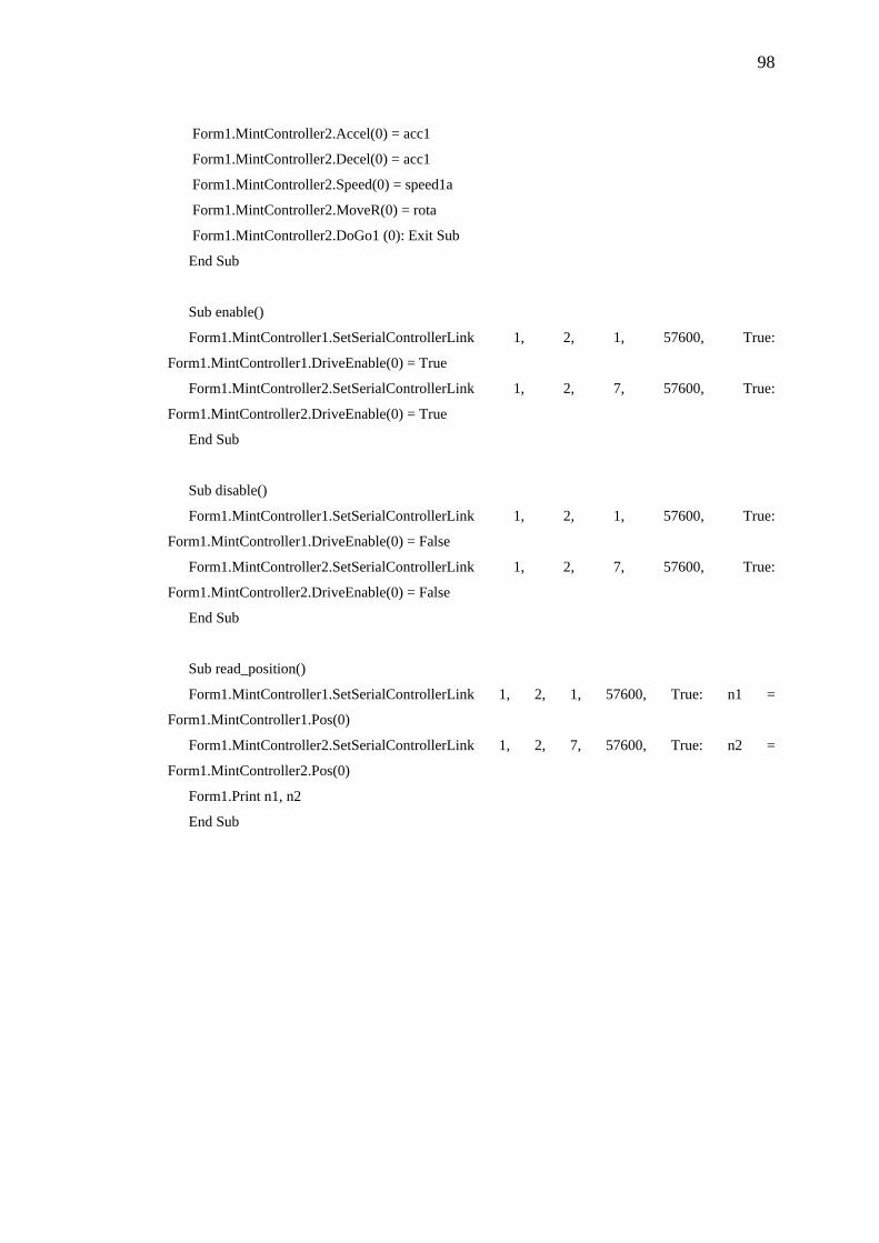
98
Form1.MintController2.Accel(0) = acc1
Form1.MintController2.Decel(0) = acc1
Form1.MintController2.Speed(0) = speed1a
Form1.MintController2.MoveR(0) = rota
Form1.MintController2.DoGo1 (0): Exit Sub
End Sub
Sub enable()
Form1.MintController1.SetSerialControllerLink 1, 2, 1, 57600, True:
Form1.MintController1.DriveEnable(0) = True
Form1.MintController2.SetSerialControllerLink 1, 2, 7, 57600, True:
Form1.MintController2.DriveEnable(0) = True
End Sub
Sub disable()
Form1.MintController1.SetSerialControllerLink 1, 2, 1, 57600, True:
Form1.MintController1.DriveEnable(0) = False
Form1.MintController2.SetSerialControllerLink 1, 2, 7, 57600, True:
Form1.MintController2.DriveEnable(0) = False
End Sub
Sub read_position()
Form1.MintController1.SetSerialControllerLink 1, 2, 1, 57600, True: n1 =
Form1.MintController1.Pos(0)
Form1.MintController2.SetSerialControllerLink 1, 2, 7, 57600, True: n2 =
Form1.MintController2.Pos(0)
Form1.Print n1, n2
End Sub
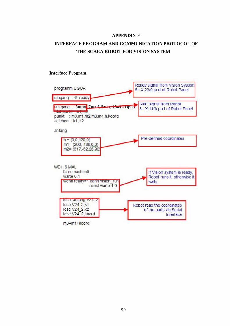
APPENDIX E
INTERFACE PROGRAM AND COMMUNICATION PROTOCOL OF
THE SCARA ROBOT FOR VISION SYSTEM
Interface Program
99
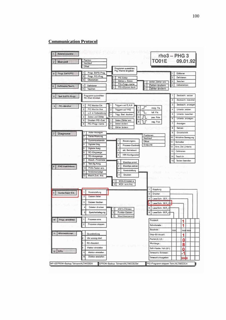
100
Communication Protocol