Embed Size (px)
Citation preview
COMPUTER NETWORKS - UNIT 4 Y3/S5
DEPT OF CSE,RGCET. Page 1
UNIT IV
TRANSPORT LAYER
Introduction:
The network layer provides end-to-end packet delivery using data-grams or virtual circuits. The
transport layer builds on the network layer to provide data transport from a process on a source machine to a
process on a destination machine with a desired level of reliability that is independent of the physical networks
currently in use. It provides the abstractions that applications need to use the network.
Transport Entity: The hardware and/or software which make use of services provided by the network layer,
(within the transport layer) is called transport entity.
Transport Service Provider: Layers 1 to 4 are called Transport Service Provider.
Transport Service User: The upper layers i.e., layers 5 to 7 are called Transport Service User.
Transport Service Primitives: Which allow transport users (application programs) to access the transport
service.
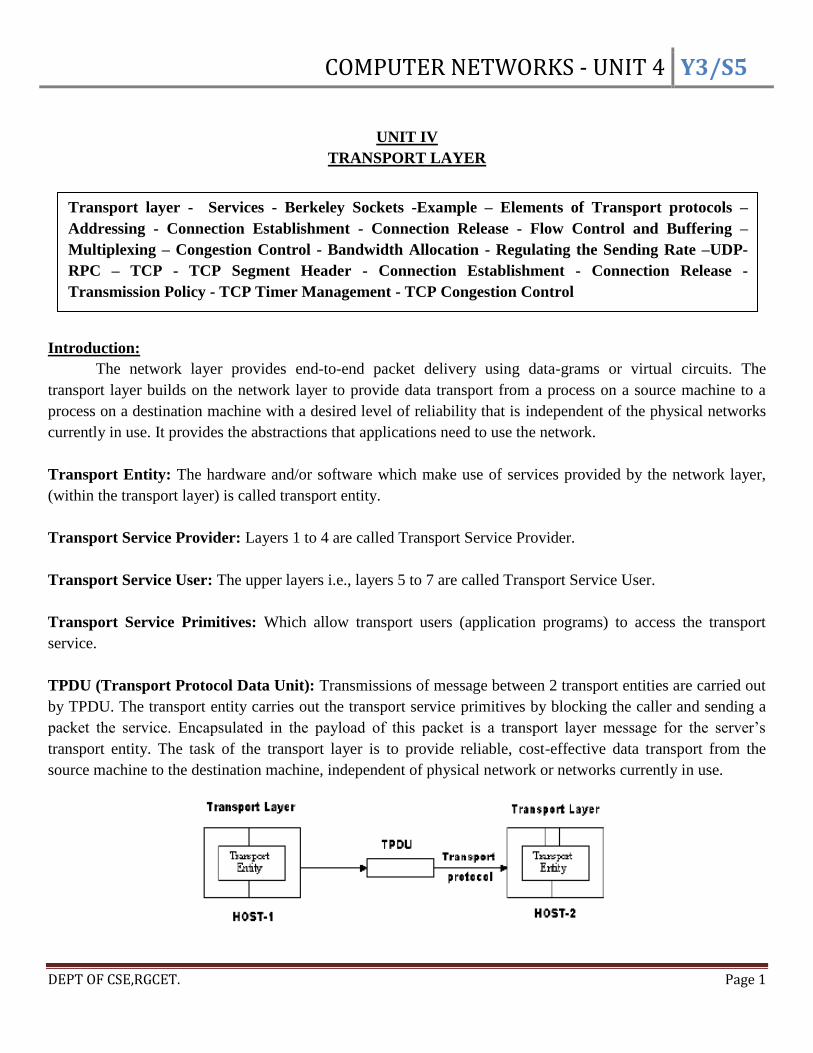
TPDU (Transport Protocol Data Unit): Transmissions of message between 2 transport entities are carried out
by TPDU. The transport entity carries out the transport service primitives by blocking the caller and sending a
packet the service. Encapsulated in the payload of this packet is a transport layer message for the server’s
transport entity. The task of the transport layer is to provide reliable, cost-effective data transport from the
source machine to the destination machine, independent of physical network or networks currently in use.
Transport layer - Services - Berkeley Sockets -Example – Elements of Transport protocols –
Addressing - Connection Establishment - Connection Release - Flow Control and Buffering –
Multiplexing – Congestion Control - Bandwidth Allocation - Regulating the Sending Rate –UDP-
RPC – TCP - TCP Segment Header - Connection Establishment - Connection Release -
Transmission Policy - TCP Timer Management - TCP Congestion Control
COMPUTER NETWORKS - UNIT 4 Y3/S5
DEPT OF CSE,RGCET. Page 2
TRANSPORT SERVICE
1.Services Provided to the Upper Layers
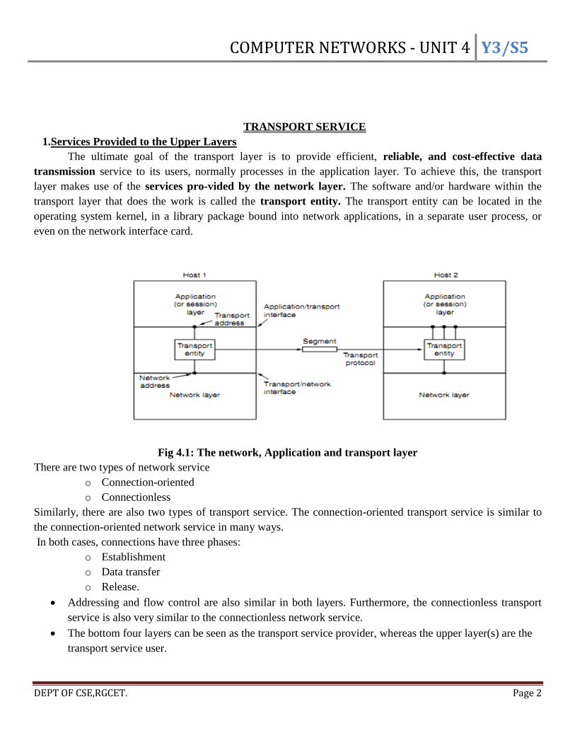
The ultimate goal of the transport layer is to provide efficient, reliable, and cost-effective data
transmission service to its users, normally processes in the application layer. To achieve this, the transport
layer makes use of the services pro-vided by the network layer. The software and/or hardware within the
transport layer that does the work is called the transport entity. The transport entity can be located in the
operating system kernel, in a library package bound into network applications, in a separate user process, or
even on the network interface card.
Fig 4.1: The network, Application and transport layer
There are two types of network service
o Connection-oriented
o Connectionless
Similarly, there are also two types of transport service. The connection-oriented transport service is similar to
the connection-oriented network service in many ways.
In both cases, connections have three phases:
o Establishment
o Data transfer
o Release.
Addressing and flow control are also similar in both layers. Furthermore, the connectionless transport
service is also very similar to the connectionless network service.
The bottom four layers can be seen as the transport service provider, whereas the upper layer(s) are the
transport service user.
COMPUTER NETWORKS - UNIT 4 Y3/S5
DEPT OF CSE,RGCET. Page 3
2. Transport Service Primitives
To allow users to access the transport service, the transport layer must provide some operations to
application programs, that is, a transport service interface. Each transport service has its own interface.
The transport service is similar to the network service, but there are also some important differences.
The main difference is that the network service is intended to model the service offered by real
networks. Real networks can lose packets, so the network service is generally unreliable.
The (connection-oriented) transport service, in contrast, is reliable
As an example, consider two processes connected by pipes in UNIX. They assume the connection
between them is perfect. They do not want to know about acknowledgements, lost packets, congestion, or
anything like that. What they want is a 100 percent reliable connection. Process A puts data into one end of the
pipe, and process B takes it out of the other.
A second difference between the network service and transport service is whom the services are
intended for. The network service is used only by the transport entities. Consequently, the transport service
must be convenient and easy to use.
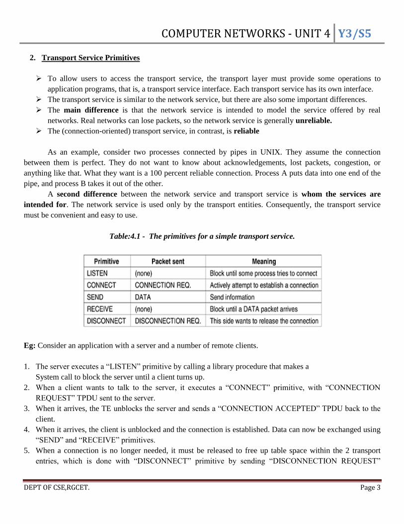
Table:4.1 - The primitives for a simple transport service.
Eg: Consider an application with a server and a number of remote clients.
1. The server executes a “LISTEN” primitive by calling a library procedure that makes a
System call to block the server until a client turns up.
2. When a client wants to talk to the server, it executes a “CONNECT” primitive, with “CONNECTION
REQUEST” TPDU sent to the server.
3. When it arrives, the TE unblocks the server and sends a “CONNECTION ACCEPTED” TPDU back to the
client.
4. When it arrives, the client is unblocked and the connection is established. Data can now be exchanged using
“SEND” and “RECEIVE” primitives.
5. When a connection is no longer needed, it must be released to free up table space within the 2 transport
entries, which is done with “DISCONNECT” primitive by sending “DISCONNECTION REQUEST”
COMPUTER NETWORKS - UNIT 4 Y3/S5
DEPT OF CSE,RGCET. Page 4
TPDU. This disconnection can b done either by asymmetric variant (connection is released, depending on
other one) or by symmetric variant (connection is released, independent of other one).
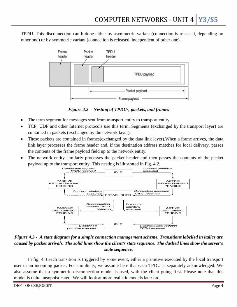
Figure 4.2 - Nesting of TPDUs, packets, and frames
The term segment for messages sent from transport entity to transport entity.
TCP, UDP and other Internet protocols use this term. Segments (exchanged by the transport layer) are
contained in packets (exchanged by the network layer).
These packets are contained in frames(exchanged by the data link layer).When a frame arrives, the data
link layer processes the frame header and, if the destination address matches for local delivery, passes
the contents of the frame payload field up to the network entity.
The network entity similarly processes the packet header and then passes the contents of the packet
payload up to the transport entity. This nesting is illustrated in Fig. 4.2.
Figure 4.3 - A state diagram for a simple connection management scheme. Transitions labelled in italics are
caused by packet arrivals. The solid lines show the client's state sequence. The dashed lines show the server's
state sequence.
In fig. 4.3 each transition is triggered by some event, either a primitive executed by the local transport
user or an incoming packet. For simplicity, we assume here that each TPDU is separately acknowledged. We
also assume that a symmetric disconnection model is used, with the client going first. Please note that this
model is quite unsophisticated. We will look at more realistic models later on.
COMPUTER NETWORKS - UNIT 4 Y3/S5
DEPT OF CSE,RGCET. Page 5
BERKLEY SOCKETS
These primitives are socket primitives used in Berkley UNIX for TCP.
The socket primitives are mainly used for TCP. These sockets were first released as part of the Berkeley
UNIX 4.2BSD software distribution in 1983. They quickly became popular. The primitives are now widely
used for Internet programming on many operating systems, especially UNIX -based systems, and there is a
socket-style API for Windows called ‘‘winsock.’’
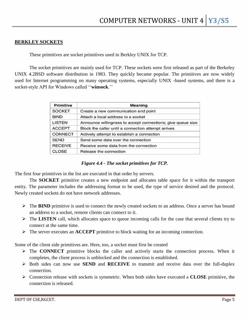
Figure 4.4 - The socket primitives for TCP.
The first four primitives in the list are executed in that order by servers.
The SOCKET primitive creates a new endpoint and allocates table space for it within the transport
entity. The parameter includes the addressing format to be used, the type of service desired and the protocol.
Newly created sockets do not have network addresses.
The BIND primitive is used to connect the newly created sockets to an address. Once a server has bound
an address to a socket, remote clients can connect to it.
The LISTEN call, which allocates space to queue incoming calls for the case that several clients try to
connect at the same time.
The server executes an ACCEPT primitive to block waiting for an incoming connection.
Some of the client side primitives are. Here, too, a socket must first be created
The CONNECT primitive blocks the caller and actively starts the connection process. When it
completes, the client process is unblocked and the connection is established.
Both sides can now use SEND and RECEIVE to transmit and receive data over the full-duplex
connection.
Connection release with sockets is symmetric. When both sides have executed a CLOSE primitive, the
connection is released.
COMPUTER NETWORKS - UNIT 4 Y3/S5
DEPT OF CSE,RGCET. Page 6
ELEMENTS OF TRANSPORT PROTOCOLS
The transport service is implemented by a transport protocol used between the two transport entities. The
transport protocols resemble the data link protocols. Both have to deal with error control, sequencing, and flow
control, among other issues. The difference transport protocol and data link protocol depends upon the
environment in which they are operated.
These differences are due to major dissimilarities between the environments in which the two protocols
operate, as shown in Fig.
At the data link layer, two routers communicate directly via a physical channel, whether wired or
wireless, whereas at the transport layer, this physical channel is replaced by the entire network. This difference
has many important implications for the protocols.
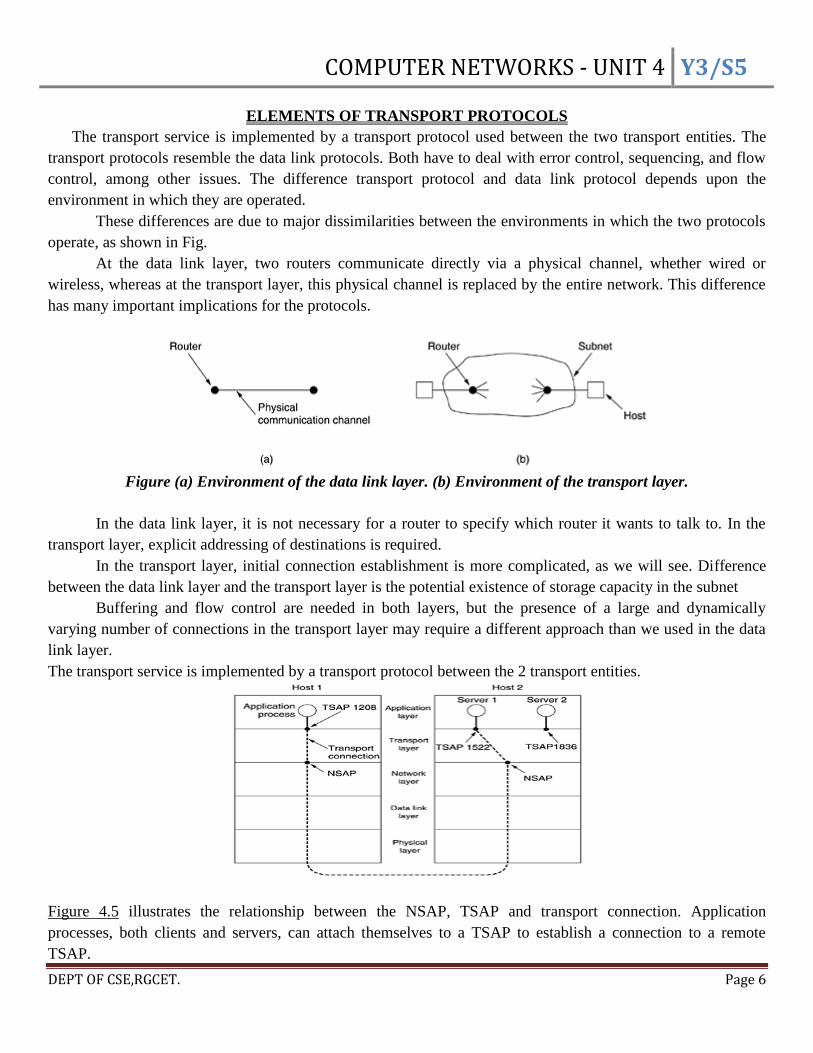
Figure (a) Environment of the data link layer. (b) Environment of the transport layer.
In the data link layer, it is not necessary for a router to specify which router it wants to talk to. In the
transport layer, explicit addressing of destinations is required.
In the transport layer, initial connection establishment is more complicated, as we will see. Difference
between the data link layer and the transport layer is the potential existence of storage capacity in the subnet
Buffering and flow control are needed in both layers, but the presence of a large and dynamically
varying number of connections in the transport layer may require a different approach than we used in the data
link layer.
The transport service is implemented by a transport protocol between the 2 transport entities.
Figure 4.5 illustrates the relationship between the NSAP, TSAP and transport connection. Application
processes, both clients and servers, can attach themselves to a TSAP to establish a connection to a remote
TSAP.
COMPUTER NETWORKS - UNIT 4 Y3/S5
DEPT OF CSE,RGCET. Page 7
These connections run through NSAPs on each host, as shown. The purpose of having TSAPs is that in
some networks, each computer has a single NSAP, so some way is needed to distinguish multiple transport end
points that share that NSAP.
The elements of transport protocols are:
1. ADDRESSING
2. Connection Establishment.
3. Connection Release.
4. Error control and flow control
5. Multiplexing.
1. ADDRESSING
When an application (e.g., a user) process wishes to set up a connection to a remote application process, it
must specify which one to connect to. The method normally used is to define transport addresses to which
processes can listen for connection requests. In the Internet, these endpoints are called ports.
There are two types of access points.
TSAP (Transport Service Access Point) to mean a specific endpoint in the transport layer.
The analogous endpoints in the network layer (i.e., network layer addresses) are not surprisingly called
NSAPs (Network Service Access Points). IP addresses are examples of NSAPs.
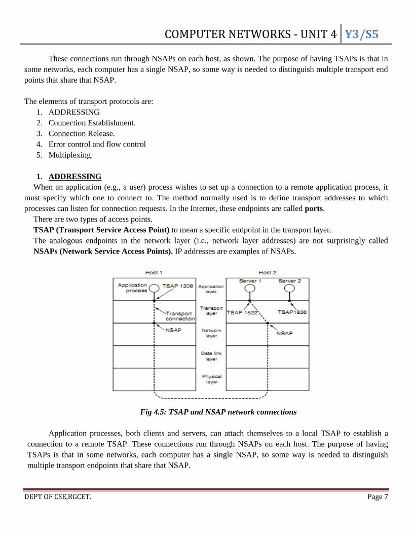
Fig 4.5: TSAP and NSAP network connections
Application processes, both clients and servers, can attach themselves to a local TSAP to establish a
connection to a remote TSAP. These connections run through NSAPs on each host. The purpose of having
TSAPs is that in some networks, each computer has a single NSAP, so some way is needed to distinguish
multiple transport endpoints that share that NSAP.
COMPUTER NETWORKS - UNIT 4 Y3/S5
DEPT OF CSE,RGCET. Page 8
A possible scenario for a transport connection is as follows:
1. A mail server process attaches itself to TSAP 1522 on host 2 to wait for an incoming call. How a
process attaches itself to a TSAP is outside the networking model and depends entirely on the local operating
system. A call such as our LISTEN might be used, for example.
2. An application process on host 1 wants to send an email message, so it attaches itself to TSAP 1208 and
issues a CONNECT request. The request specifies TSAP 1208 on host 1 as the source and TSAP 1522 on
host 2 as the destination. This action ultimately results in a transport connection being established between
the application process and the server.
3. The application process sends over the mail message.
4. The mail server responds to say that it will deliver the message.
5. The transport connection is released.
2. CONNECTION ESTABLISHMENT:
With packet lifetimes bounded, it is possible to devise a fool proof way to establish connections safely.
Packet lifetime can be bounded to a known maximum using one of the following techniques:
Restricted subnet design
Putting a hop counter in each packet
Time stamping in each packet
Using a 3-way hand shake, a connection can be established. This establishment protocol doesn’t require both
sides to begin sending with the same sequence number.
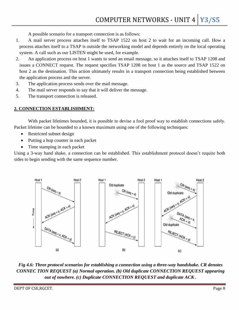
Fig 4.6: Three protocol scenarios for establishing a connection using a three-way handshake. CR denotes
CONNEC TION REQUEST (a) Normal operation. (b) Old duplicate CONNECTION REQUEST appearing
out of nowhere. (c) Duplicate CONNECTION REQUEST and duplicate ACK .
COMPUTER NETWORKS - UNIT 4 Y3/S5
DEPT OF CSE,RGCET. Page 9
The first technique includes any method that prevents packets from looping, combined with some way
of bounding delay including congestion over the longest possible path. It is difficult, given that
internets may range from a single city to international in scope.
The second method consists of having the hop count initialized to some appropriate value and
decremented each time the packet is forwarded. The network protocol simply discards any packet
whose hop counter becomes zero.
The third method requires each packet to bear the time it was created, with the routers agreeing to
discard any packet older than some agreed-upon time.
In fig (A) Tomlinson (1975) introduced the three-way handshake.
This establishment protocol involves one peer checking with the other that the connection request is
indeed current. Host 1 chooses a sequence number, x , and sends a CONNECTION REQUEST
segment containing it to host 2. Host 2replies with an ACK segment acknowledging x and announcing
its own initial sequence number, y.
Finally, host 1 acknowledges host 2’s choice of an initial sequence number in the first data segment that
it sends
In fig (B) the first segment is a delayed duplicate CONNECTION REQUEST from an old connection.
This segment arrives at host 2 without host 1’s knowledge. Host 2 reacts to this segment by sending
host1an ACK segment, in effect asking for verification that host 1 was indeed trying to set up a new
connection.
When host 1 rejects host 2’s attempt to establish a connection, host 2 realizes that it was tricked by a
delayed duplicate and abandons the connection. In this way, a delayed duplicate does no damage.
The worst case is when both a delayed CONNECTION REQUEST and an ACK are floating around in
the subnet.
In fig (C) previous example, host 2 gets a delayed CONNECTION REQUEST and replies to it.
At this point, it is crucial to realize that host 2 has proposed using y as the initial sequence number for
host 2 to host 1 traffic, knowing full well that no segments containing sequence number y or
acknowledgements to y are still in existence.
When the second delayed segment arrives at host 2, the fact that z has been acknowledged rather than y
tells host 2 that this, too, is an old duplicate.
COMPUTER NETWORKS - UNIT 4 Y3/S5
DEPT OF CSE,RGCET. Page 10
The important thing to realize here is that there is no combination of old segments that can cause the
protocol to fail and have a connection set up by accident when no one wants it.
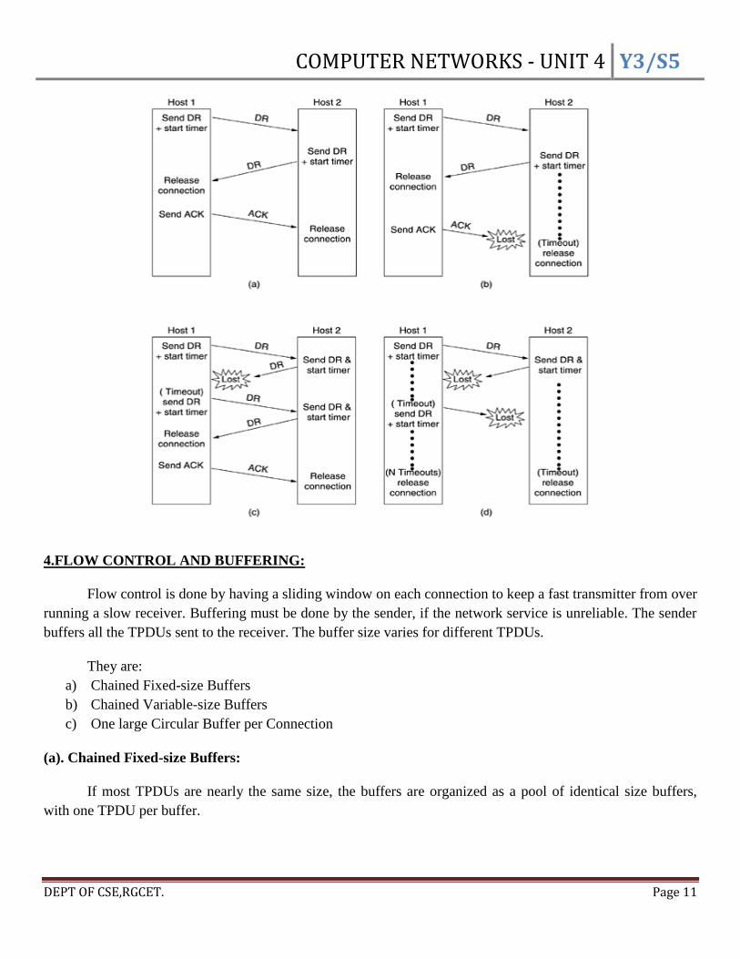
3.CONNECTION RELEASE:
A connection is released using either asymmetric or symmetric variant. But, the improved protocol for
releasing a connection is a 3-way handshake protocol.
There are two styles of terminating a connection:
1) Asymmetric release and
2) Symmetric release.
Asymmetric release is the way the telephone system works: when one party hangs up, the
connection is broken. Symmetric release treats the connection as two separate unidirectional
connections and requires each one to be released separately.
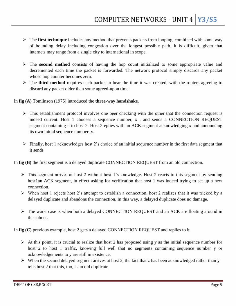
Fig-(a) Fig-(b) Fig-(c) Fig-(d)
One of the user sends a
DISCONNECTION
REQUEST TPDU in
order to initiate
connection release.
When it arrives, the
recipient sends back a
DR-TPDU, too, and
starts a timer.
When this DR arrives,
the original sender
sends back an ACK-
TPDU and releases the
connection.
Finally, when the
ACK-TPDU arrives,
the receiver also
releases the connection.
Initial process is done
in the same way as in
fig-(a).
If the final ACK-TPDU
is lost, the situation is
saved by the timer.
When the timer is
expired, the connection
is released.
If the second DR is lost, the user initiating the disconnection will not receive the expected response, and will timeout and starts all over again.
Same as in fig-( c)
except that all repeated
attempts to retransmit
the
DR is assumed to be
failed due to lost
TPDUs. After ‘N’
entries, the sender just
gives up and
releases the
connection.
COMPUTER NETWORKS - UNIT 4 Y3/S5
DEPT OF CSE,RGCET. Page 11
4.FLOW CONTROL AND BUFFERING:
Flow control is done by having a sliding window on each connection to keep a fast transmitter from over
running a slow receiver. Buffering must be done by the sender, if the network service is unreliable. The sender
buffers all the TPDUs sent to the receiver. The buffer size varies for different TPDUs.
They are:
a) Chained Fixed-size Buffers
b) Chained Variable-size Buffers
c) One large Circular Buffer per Connection
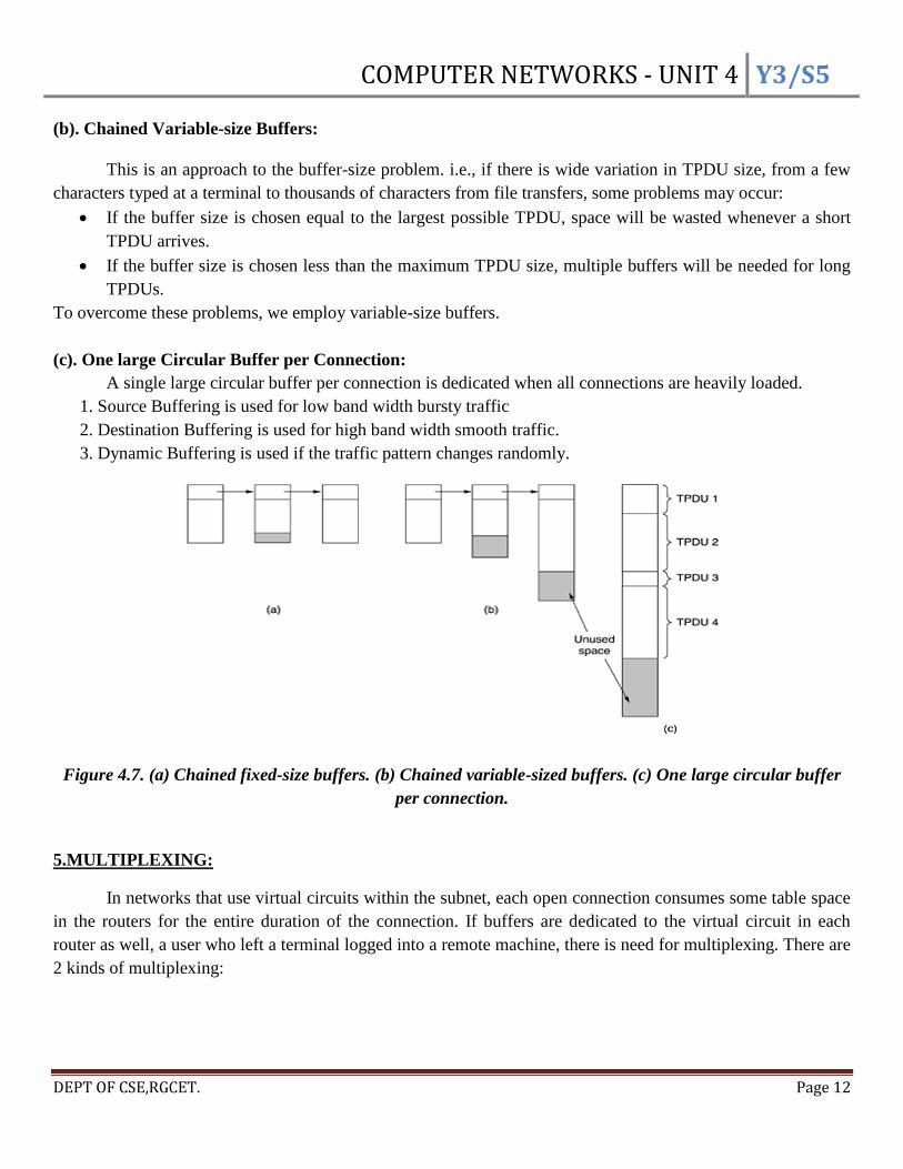
(a). Chained Fixed-size Buffers:
If most TPDUs are nearly the same size, the buffers are organized as a pool of identical size buffers,
with one TPDU per buffer.
COMPUTER NETWORKS - UNIT 4 Y3/S5
DEPT OF CSE,RGCET. Page 12
(b). Chained Variable-size Buffers:
This is an approach to the buffer-size problem. i.e., if there is wide variation in TPDU size, from a few
characters typed at a terminal to thousands of characters from file transfers, some problems may occur:
If the buffer size is chosen equal to the largest possible TPDU, space will be wasted whenever a short
TPDU arrives.
If the buffer size is chosen less than the maximum TPDU size, multiple buffers will be needed for long
TPDUs.
To overcome these problems, we employ variable-size buffers.
(c). One large Circular Buffer per Connection:
A single large circular buffer per connection is dedicated when all connections are heavily loaded.
1. Source Buffering is used for low band width bursty traffic
2. Destination Buffering is used for high band width smooth traffic.
3. Dynamic Buffering is used if the traffic pattern changes randomly.
Figure 4.7. (a) Chained fixed-size buffers. (b) Chained variable-sized buffers. (c) One large circular buffer
per connection.
5.MULTIPLEXING:
In networks that use virtual circuits within the subnet, each open connection consumes some table space
in the routers for the entire duration of the connection. If buffers are dedicated to the virtual circuit in each
router as well, a user who left a terminal logged into a remote machine, there is need for multiplexing. There are
2 kinds of multiplexing:
COMPUTER NETWORKS - UNIT 4 Y3/S5
DEPT OF CSE,RGCET. Page 13
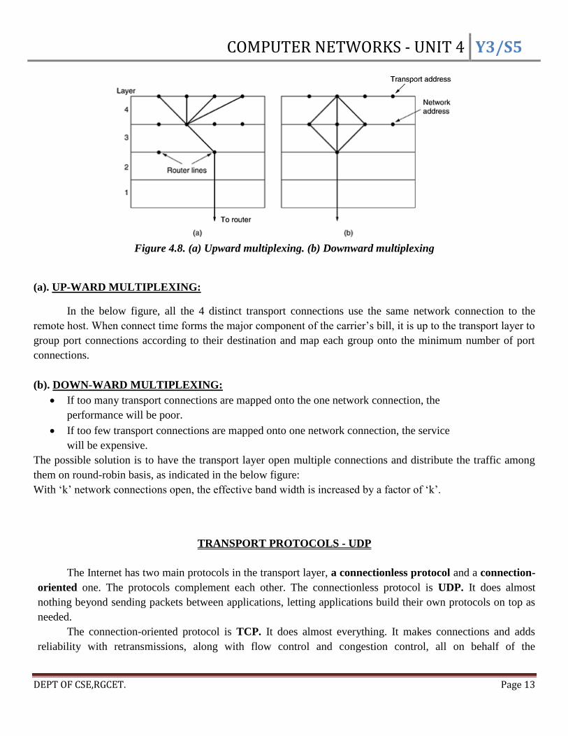
Figure 4.8. (a) Upward multiplexing. (b) Downward multiplexing
(a). UP-WARD MULTIPLEXING:
In the below figure, all the 4 distinct transport connections use the same network connection to the
remote host. When connect time forms the major component of the carrier’s bill, it is up to the transport layer to
group port connections according to their destination and map each group onto the minimum number of port
connections.
(b). DOWN-WARD MULTIPLEXING:
If too many transport connections are mapped onto the one network connection, the
performance will be poor.
If too few transport connections are mapped onto one network connection, the service
will be expensive.
The possible solution is to have the transport layer open multiple connections and distribute the traffic among
them on round-robin basis, as indicated in the below figure:
With ‘k’ network connections open, the effective band width is increased by a factor of ‘k’.
TRANSPORT PROTOCOLS - UDP
The Internet has two main protocols in the transport layer, a connectionless protocol and a connection-
oriented one. The protocols complement each other. The connectionless protocol is UDP. It does almost
nothing beyond sending packets between applications, letting applications build their own protocols on top as
needed.
The connection-oriented protocol is TCP. It does almost everything. It makes connections and adds
reliability with retransmissions, along with flow control and congestion control, all on behalf of the
COMPUTER NETWORKS - UNIT 4 Y3/S5
DEPT OF CSE,RGCET. Page 14
applications that use it. Since UDP is a transport layer protocol that typically runs in the operating system and
protocols that use UDP typically run in user s pace, these uses might be considered applications.
INTROUCTION TO UDP
The Internet protocol suite supports a connectionless transport protocol called UDP (User Datagram
Protocol). UDP provides a way for applications to send encapsulated IP datagrams without having to
establish a connection.
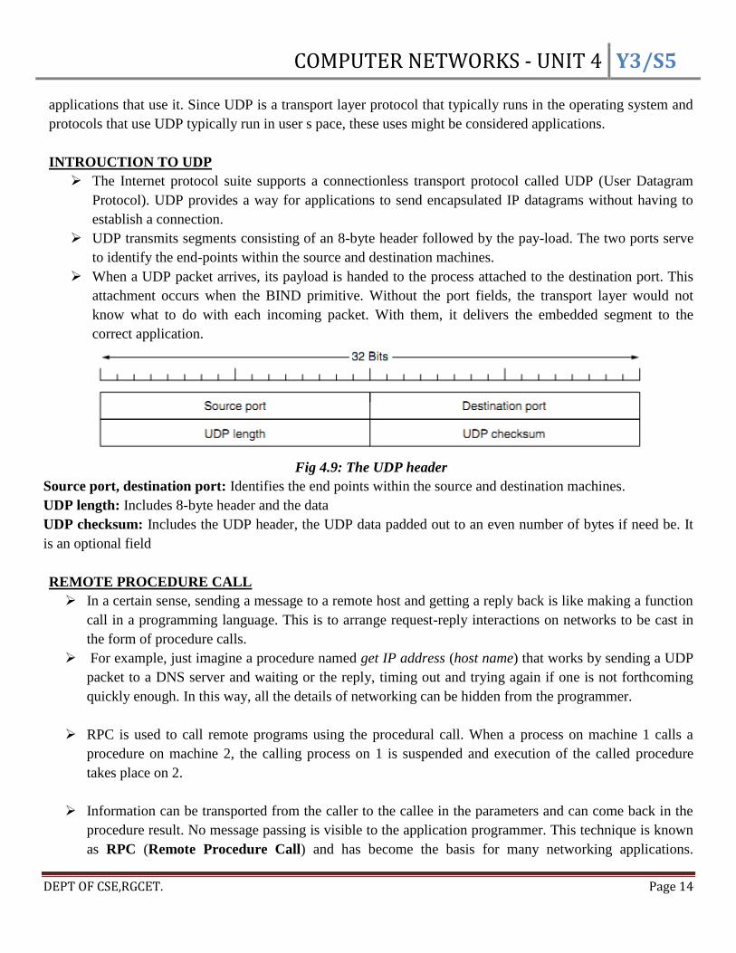
UDP transmits segments consisting of an 8-byte header followed by the pay-load. The two ports serve
to identify the end-points within the source and destination machines.
When a UDP packet arrives, its payload is handed to the process attached to the destination port. This
attachment occurs when the BIND primitive. Without the port fields, the transport layer would not
know what to do with each incoming packet. With them, it delivers the embedded segment to the
correct application.
Fig 4.9: The UDP header
Source port, destination port: Identifies the end points within the source and destination machines.
UDP length: Includes 8-byte header and the data
UDP checksum: Includes the UDP header, the UDP data padded out to an even number of bytes if need be. It
is an optional field
REMOTE PROCEDURE CALL
In a certain sense, sending a message to a remote host and getting a reply back is like making a function
call in a programming language. This is to arrange request-reply interactions on networks to be cast in
the form of procedure calls.
For example, just imagine a procedure named get IP address (host name) that works by sending a UDP
packet to a DNS server and waiting or the reply, timing out and trying again if one is not forthcoming
quickly enough. In this way, all the details of networking can be hidden from the programmer.
RPC is used to call remote programs using the procedural call. When a process on machine 1 calls a
procedure on machine 2, the calling process on 1 is suspended and execution of the called procedure
takes place on 2.
Information can be transported from the caller to the callee in the parameters and can come back in the
procedure result. No message passing is visible to the application programmer. This technique is known
as RPC (Remote Procedure Call) and has become the basis for many networking applications.
COMPUTER NETWORKS - UNIT 4 Y3/S5
DEPT OF CSE,RGCET. Page 15
Traditionally, the calling procedure is known as the client and the called procedure is known as the
server.
In the simplest form, to call a remote procedure, the client program must be bound with a small library
procedure, called the client stub,that represents the server procedure in the client’s address space.
Similarly, the server is bound with a procedure called the server stub. These procedures hide the fact
that the procedure call from the client to the server is not local.
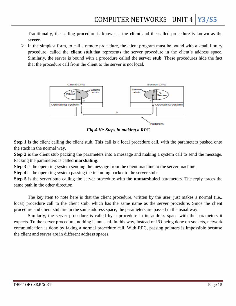
Fig 4.10: Steps in making a RPC
Step 1 is the client calling the client stub. This call is a local procedure call, with the parameters pushed onto
the stack in the normal way.
Step 2 is the client stub packing the parameters into a message and making a system call to send the message.
Packing the parameters is called marshaling.
Step 3 is the operating system sending the message from the client machine to the server machine.
Step 4 is the operating system passing the incoming packet to the server stub.
Step 5 is the server stub calling the server procedure with the unmarshaled parameters. The reply traces the
same path in the other direction.
The key item to note here is that the client procedure, written by the user, just makes a normal (i.e.,
local) procedure call to the client stub, which has the same name as the server procedure. Since the client
procedure and client stub are in the same address space, the parameters are passed in the usual way.
Similarly, the server procedure is called by a procedure in its address space with the parameters it
expects. To the server procedure, nothing is unusual. In this way, instead of I/O being done on sockets, network
communication is done by faking a normal procedure call. With RPC, passing pointers is impossible because
the client and server are in different address spaces.
COMPUTER NETWORKS - UNIT 4 Y3/S5
DEPT OF CSE,RGCET. Page 16
TCP (TRANSMISSION CONTROL PROTOCOL)
It was specifically designed to provide a reliable end-to end byte stream over an unreliable network. It
was designed to adapt dynamically to properties of the inter network and to be robust in the face of many kinds
of failures.
Each machine supporting TCP has a TCP transport entity, which accepts user data streams from local
processes, breaks them up into pieces not exceeding 64kbytes and sends each piece as a separate IP datagram.
When these datagrams arrive at a machine, they are given to TCP entity, which reconstructs the original byte
streams. It is up to TCP to time out and retransmits them as needed, also to reassemble datagrams into messages
in proper sequence.
The different issues to be considered are:
1. The TCP Service Model
2. The TCP Protocol
3. The TCP Segment Header
4. The Connection Management
5. TCP Transmission Policy
6. TCP Congestion Control
7. TCP Timer Management.
The TCP Service Model
TCP service is obtained by having both the sender and receiver create end points called SOCKETS
Each socket has a socket number(address)consisting of the IP address of the host, called a “PORT” ( =
TSAP )
To obtain TCP service a connection must be explicitly established between a socket on the sending
machine and a socket on the receiving machine
All TCP connections are full duplex and point to point i.e., multicasting or broadcasting is not
supported.
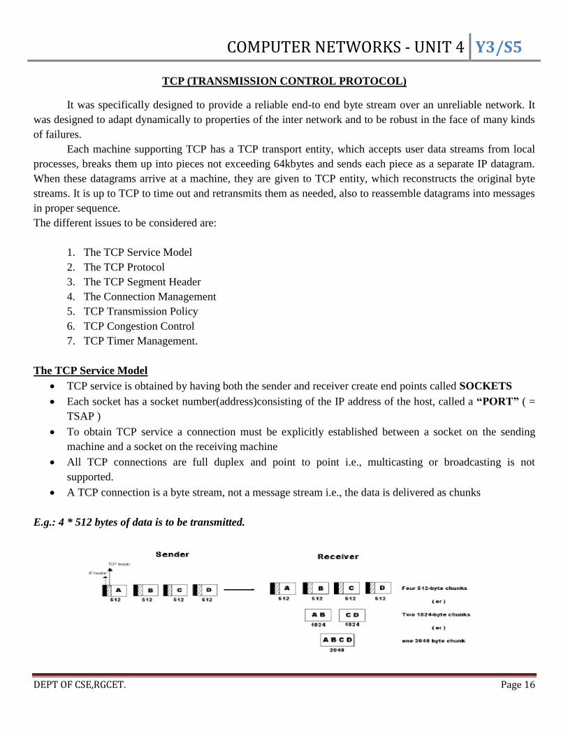
A TCP connection is a byte stream, not a message stream i.e., the data is delivered as chunks
E.g.: 4 * 512 bytes of data is to be transmitted.
COMPUTER NETWORKS - UNIT 4 Y3/S5
DEPT OF CSE,RGCET. Page 17
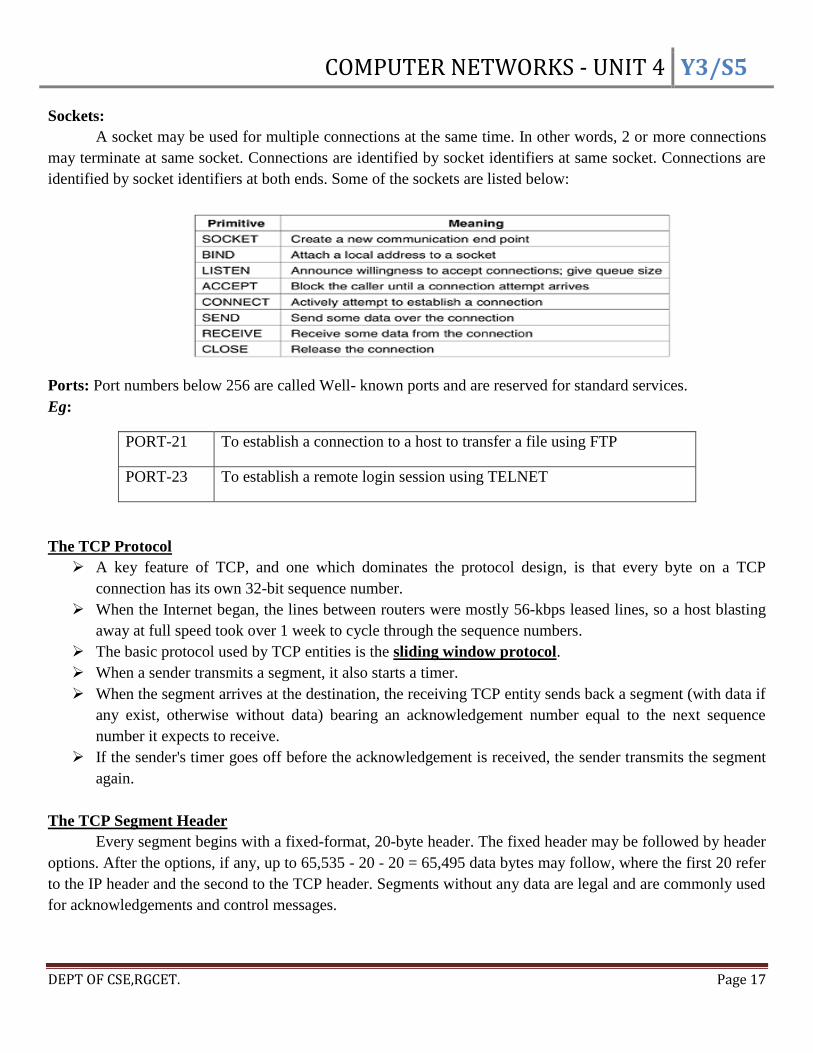
Sockets:
A socket may be used for multiple connections at the same time. In other words, 2 or more connections
may terminate at same socket. Connections are identified by socket identifiers at same socket. Connections are
identified by socket identifiers at both ends. Some of the sockets are listed below:
Ports: Port numbers below 256 are called Well- known ports and are reserved for standard services.
Eg:
PORT-21 To establish a connection to a host to transfer a file using FTP
PORT-23 To establish a remote login session using TELNET
The TCP Protocol
A key feature of TCP, and one which dominates the protocol design, is that every byte on a TCP
connection has its own 32-bit sequence number.
When the Internet began, the lines between routers were mostly 56-kbps leased lines, so a host blasting
away at full speed took over 1 week to cycle through the sequence numbers.
The basic protocol used by TCP entities is the sliding window protocol.
When a sender transmits a segment, it also starts a timer.
When the segment arrives at the destination, the receiving TCP entity sends back a segment (with data if
any exist, otherwise without data) bearing an acknowledgement number equal to the next sequence
number it expects to receive.
If the sender's timer goes off before the acknowledgement is received, the sender transmits the segment
again.
The TCP Segment Header
Every segment begins with a fixed-format, 20-byte header. The fixed header may be followed by header
options. After the options, if any, up to 65,535 - 20 - 20 = 65,495 data bytes may follow, where the first 20 refer
to the IP header and the second to the TCP header. Segments without any data are legal and are commonly used
for acknowledgements and control messages.
COMPUTER NETWORKS - UNIT 4 Y3/S5
DEPT OF CSE,RGCET. Page 18
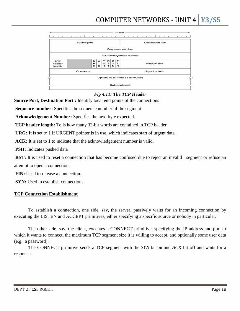
Fig 4.11: The TCP Header
Source Port, Destination Port : Identify local end points of the connections
Sequence number: Specifies the sequence number of the segment
Acknowledgement Number: Specifies the next byte expected.
TCP header length: Tells how many 32-bit words are contained in TCP header
URG: It is set to 1 if URGENT pointer is in use, which indicates start of urgent data.
ACK: It is set to 1 to indicate that the acknowledgement number is valid.
PSH: Indicates pushed data
RST: It is used to reset a connection that has become confused due to reject an invalid segment or refuse an
attempt to open a connection.
FIN: Used to release a connection.
SYN: Used to establish connections.
TCP Connection Establishment
To establish a connection, one side, say, the server, passively waits for an incoming connection by
executing the LISTEN and ACCEPT primitives, either specifying a specific source or nobody in particular.
The other side, say, the client, executes a CONNECT primitive, specifying the IP address and port to
which it wants to connect, the maximum TCP segment size it is willing to accept, and optionally some user data
(e.g., a password).
The CONNECT primitive sends a TCP segment with the SYN bit on and ACK bit off and waits for a
response.
COMPUTER NETWORKS - UNIT 4 Y3/S5
DEPT OF CSE,RGCET. Page 19
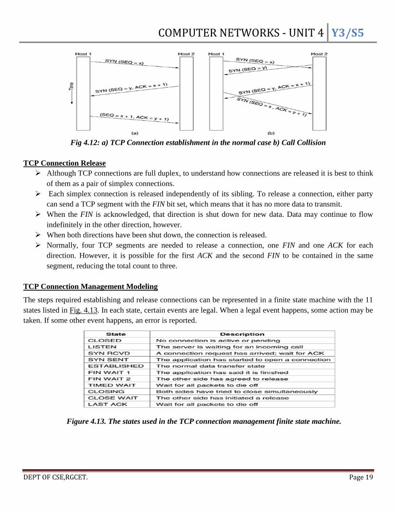
Fig 4.12: a) TCP Connection establishment in the normal case b) Call Collision
TCP Connection Release
Although TCP connections are full duplex, to understand how connections are released it is best to think
of them as a pair of simplex connections.
Each simplex connection is released independently of its sibling. To release a connection, either party
can send a TCP segment with the FIN bit set, which means that it has no more data to transmit.
When the FIN is acknowledged, that direction is shut down for new data. Data may continue to flow
indefinitely in the other direction, however.
When both directions have been shut down, the connection is released.
Normally, four TCP segments are needed to release a connection, one FIN and one ACK for each
direction. However, it is possible for the first ACK and the second FIN to be contained in the same
segment, reducing the total count to three.
TCP Connection Management Modeling
The steps required establishing and release connections can be represented in a finite state machine with the 11
states listed in Fig. 4.13. In each state, certain events are legal. When a legal event happens, some action may be
taken. If some other event happens, an error is reported.
Figure 4.13. The states used in the TCP connection management finite state machine.
COMPUTER NETWORKS - UNIT 4 Y3/S5
DEPT OF CSE,RGCET. Page 20
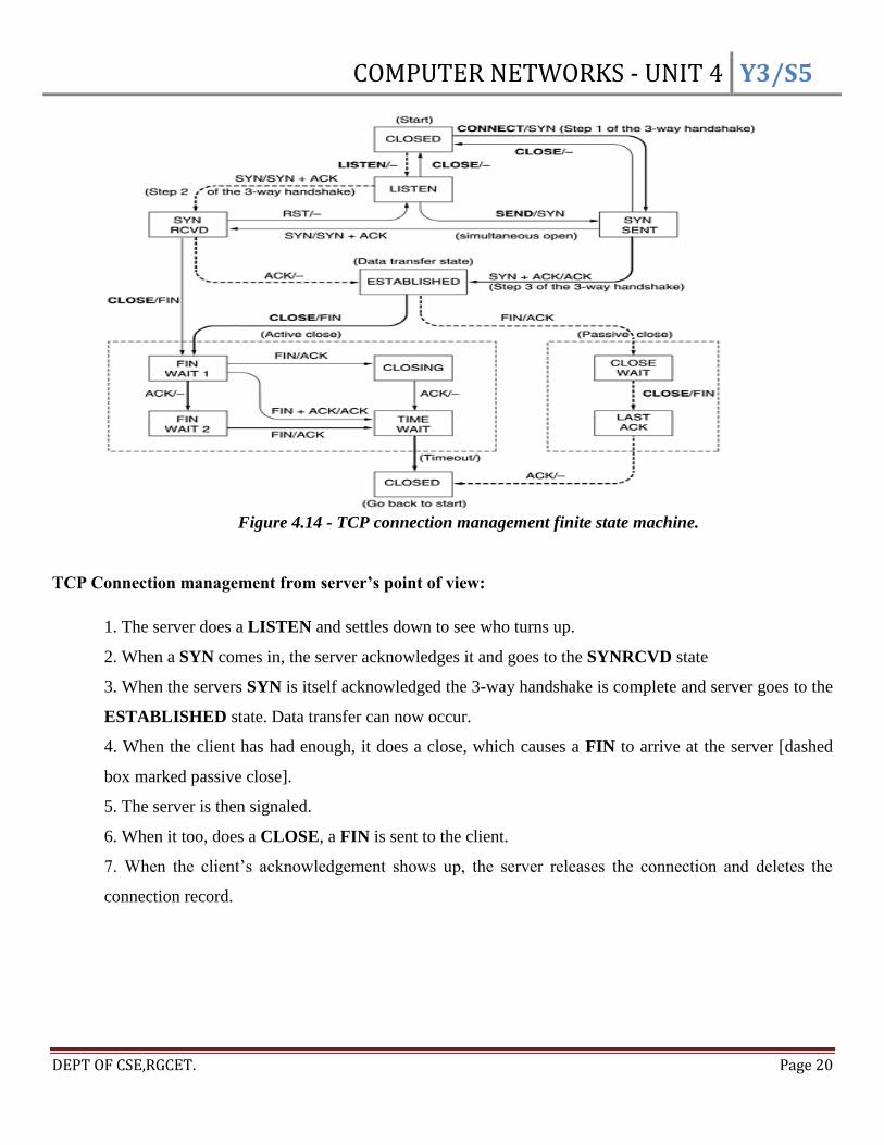
Figure 4.14 - TCP connection management finite state machine.
TCP Connection management from server’s point of view:
1. The server does a LISTEN and settles down to see who turns up.
2. When a SYN comes in, the server acknowledges it and goes to the SYNRCVD state
3. When the servers SYN is itself acknowledged the 3-way handshake is complete and server goes to the
ESTABLISHED state. Data transfer can now occur.
4. When the client has had enough, it does a close, which causes a FIN to arrive at the server [dashed
box marked passive close].
5. The server is then signaled.
6. When it too, does a CLOSE, a FIN is sent to the client.
7. When the client’s acknowledgement shows up, the server releases the connection and deletes the
connection record.
COMPUTER NETWORKS - UNIT 4 Y3/S5
DEPT OF CSE,RGCET. Page 21
TCP Transmission Policy
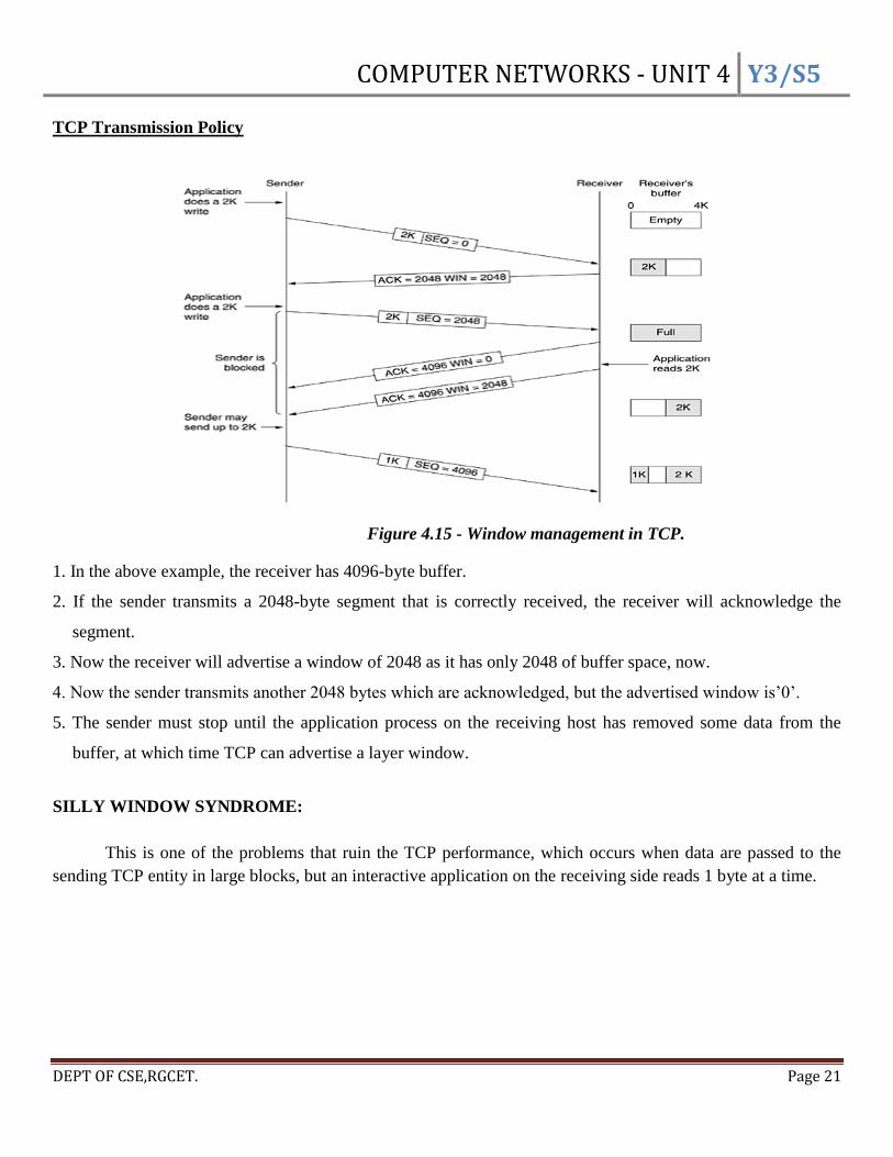
Figure 4.15 - Window management in TCP.
1. In the above example, the receiver has 4096-byte buffer.
2. If the sender transmits a 2048-byte segment that is correctly received, the receiver will acknowledge the
segment.
3. Now the receiver will advertise a window of 2048 as it has only 2048 of buffer space, now.
4. Now the sender transmits another 2048 bytes which are acknowledged, but the advertised window is’0’.
5. The sender must stop until the application process on the receiving host has removed some data from the
buffer, at which time TCP can advertise a layer window.
SILLY WINDOW SYNDROME:
This is one of the problems that ruin the TCP performance, which occurs when data are passed to the
sending TCP entity in large blocks, but an interactive application on the receiving side reads 1 byte at a time.
COMPUTER NETWORKS - UNIT 4 Y3/S5
DEPT OF CSE,RGCET. Page 22
Initially the TCP buffer on the receiving side is full and the sender knows this(win=0)
Then the interactive application reads 1 character from tcp stream.
Now, the receiving TCP sends a window update to the sender saying that it is all right to send 1 byte.
The sender obligates and sends 1 byte.
The buffer is now full, and so the receiver acknowledges the 1 byte segment but sets window to zero.
This behavior can go on forever.
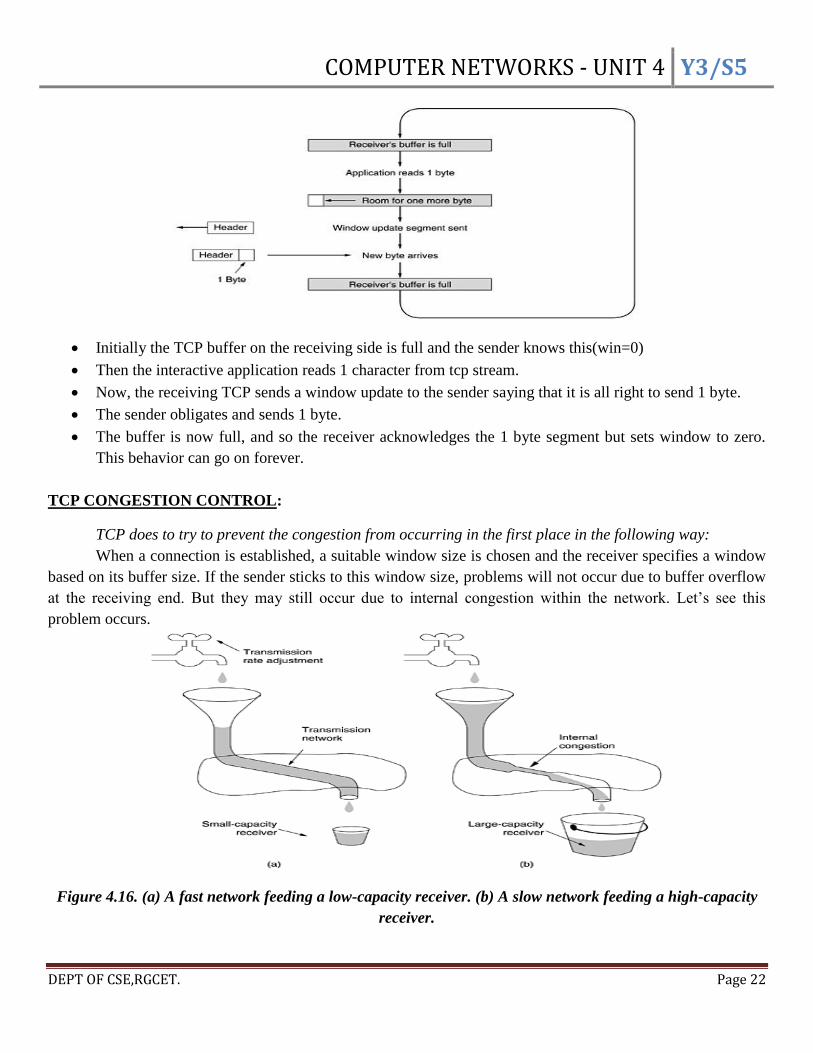
TCP CONGESTION CONTROL:
TCP does to try to prevent the congestion from occurring in the first place in the following way:
When a connection is established, a suitable window size is chosen and the receiver specifies a window
based on its buffer size. If the sender sticks to this window size, problems will not occur due to buffer overflow
at the receiving end. But they may still occur due to internal congestion within the network. Let’s see this
problem occurs.
Figure 4.16. (a) A fast network feeding a low-capacity receiver. (b) A slow network feeding a high-capacity
receiver.
COMPUTER NETWORKS - UNIT 4 Y3/S5
DEPT OF CSE,RGCET. Page 23
In fig (a): We see a thick pipe leading to a small- capacity receiver. As long as the sender does not send more
water than the bucket can contain, no water will be lost.
In fig (b): The limiting factor is not the bucket capacity, but the internal carrying capacity of the n/w. if too
much water comes in too fast, it will backup and some will be lost.
When a connection is established, the sender initializes the congestion window to the size of the max
segment in use our connection.
It then sends one max segment .if this max segment is acknowledged before the timer goes off, it adds
one segment s worth of bytes to the congestion window to make it two maximum size segments and
sends 2 segments.
As each of these segments is acknowledged, the congestion window is increased by one max segment
size.
When the congestion window is ‘n’ segments, if all ‘n’ are acknowledged on time, the congestion
window is increased by the byte count corresponding to ‘n’ segments.
The congestion window keeps growing exponentially until either a time out occurs or the receiver’s
window is reached.
The internet congestion control algorithm uses a third parameter, the “threshold” in addition to receiver
and congestion windows.
Different congestion control algorithms used by TCP are:
RTT variance Estimation.
Exponential RTO back-off Re-transmission Timer Management
Karn’s Algorithm
Slow Start
Dynamic window sizing on congestion
Fast Retransmit Window Management
Fast Recovery
TCP TIMER MANAGEMENT:
TCP uses 3 kinds of timers:
1. Retransmission timer
2. Persistence timer
3. Keep-Alive timer.
1. Retransmission timer: When a segment is sent, a timer is started. If the segment is acknowledged before the
timer expires, the timer is stopped. If on the other hand, the timer goes off before the acknowledgement comes
in, the segment is retransmitted and the timer is started again. The algorithm that constantly adjusts the time-out
interval, based on continuous measurements of n/w performance was proposed by JACOBSON and works as
follows:
COMPUTER NETWORKS - UNIT 4 Y3/S5
DEPT OF CSE,RGCET. Page 24
for each connection, TCP maintains a variable RTT, that is the best current estimate of the round trip
time to the destination inn question.
When a segment is sent, a timer is started, both to see how long the acknowledgement takes and to
trigger a retransmission if it takes too long.
If the acknowledgement gets back before the timer expires, TCP measures how long the measurements
took say M
It then updates RTT according to the formula
RTT = αRTT + ( 1-α ) M
Where α = a smoothing factor that determines how much weight is given to
the old value. Typically, α =7/8
Retransmission timeout is calculated as
D = α D + ( 1-α ) | RTT-M |
Where D = another smoothed variable, Mean RTT = expected acknowledgement value
M = observed acknowledgement value
Timeout = RTT+(4*D)
2. Persistence timer:
It is designed to prevent the following deadlock:
The receiver sends an acknowledgement with a window size of ‘0’ telling the sender to wait later, the
receiver updates the window, but the packet with the update is lost now both the sender and receiver are
waiting for each other to do something
when the persistence timer goes off, the sender transmits a probe to the receiver the response to the
probe gives the window size
if it is still zero, the persistence timer is set again and the cycle repeats
if it is non zero, data can now be sent
3. Keep-Alive timer: When a connection has been idle for a long time, this timer may go off to cause one side
to check if other side is still there. If it fails to respond, the connection is terminated.
_________________