Embed Size (px)
Citation preview
RMK College of Engineering and Technology
CS 6551
Computer Networks
Department of
Electronics and Communication Engineering
Unit 1
Fundamentals and
Link Layers
Prepared by
Jai Ganesh S
Asst.Professor - ECE
Syllabus
• Building a network
• Requirements
• Layering and protocols
• Internet architecture
• Network software performance
• Link layer services
• Framing
• Flow control and Error Control
• Error detection
Recalling the past….
• Before jumping in the syllabus lets revise some fundamentals of computer
networks
• Characteristics of computer communication systems.
• Components of data communication
• Transmission modes

1. Characteristics of computer communication
Correct
Delivery
Accuracy
Timely
Delivery
Jitter
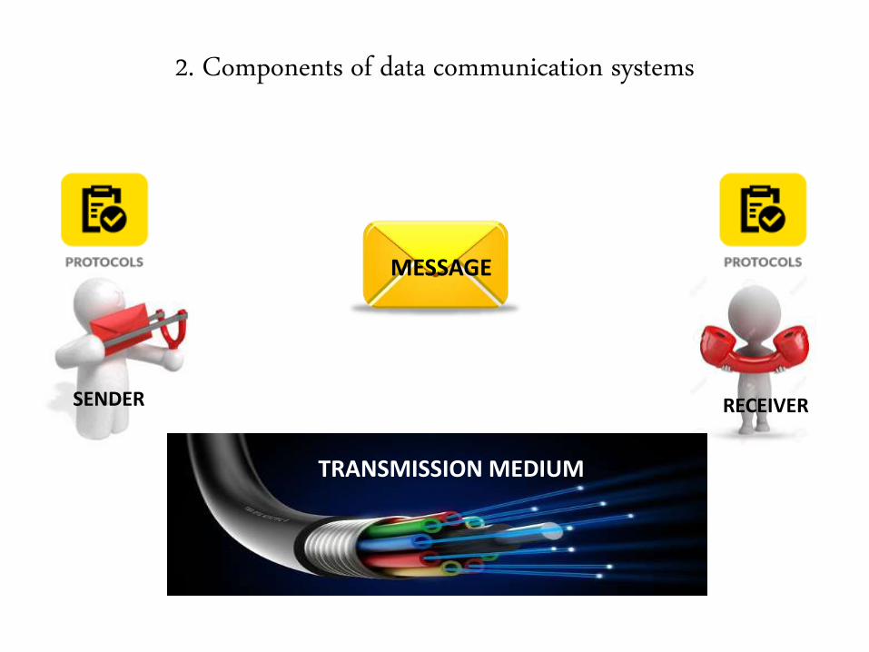
2. Components of data communication systems
MESSAGE
SENDER RECEIVER
TRANSMISSION MEDIUM
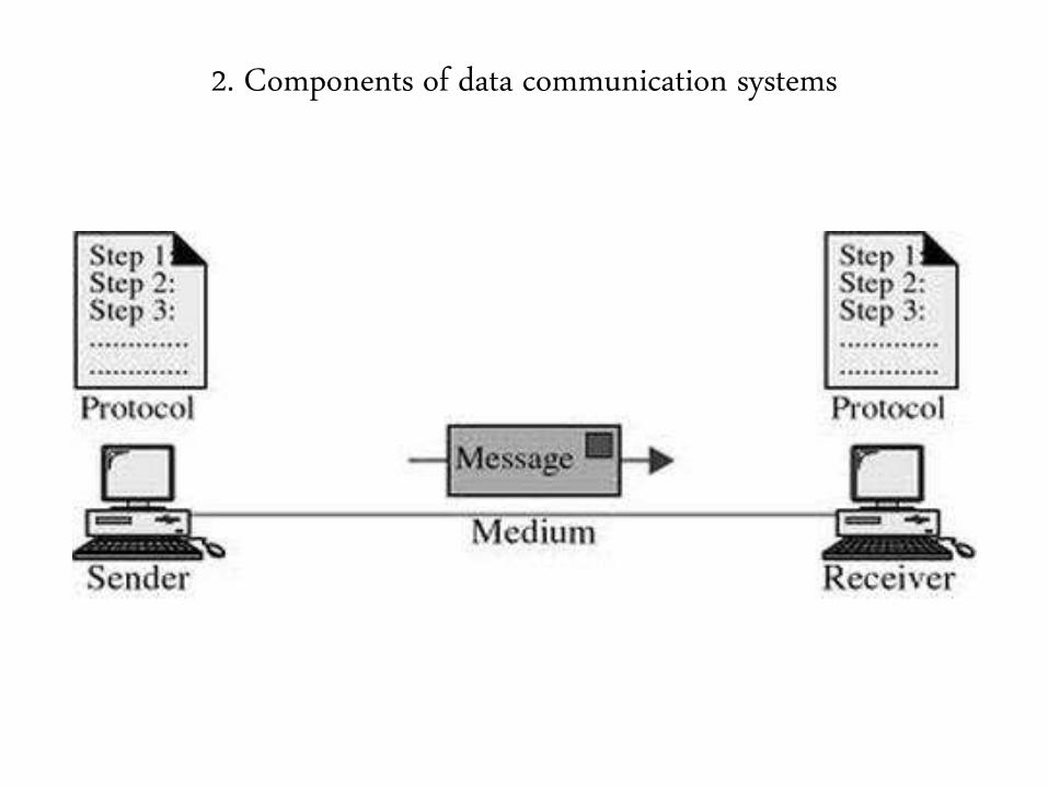
2. Components of data communication systems
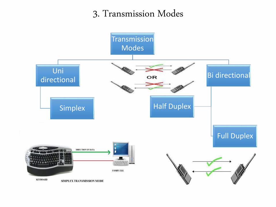
3. Transmission Modes
Transmission Modes
Unidirectional
Simplex
Bi directional
Half Duplex
Full Duplex

Getting Inside the syllabus
Fundamentals Syllabus
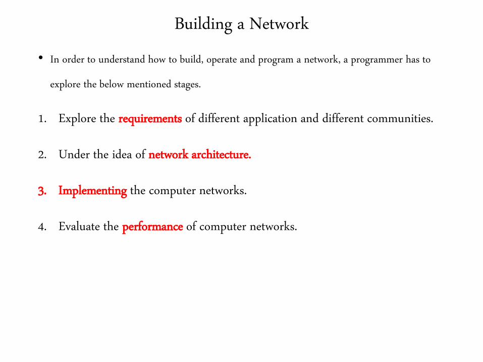
Building a Network
• In order to understand how to build, operate and program a network, a programmer has to
explore the below mentioned stages.
1. Explore the requirements of different application and different communities.
2. Under the idea of network architecture.
3. Implementing the computer networks.
4. Evaluate the performance of computer networks.
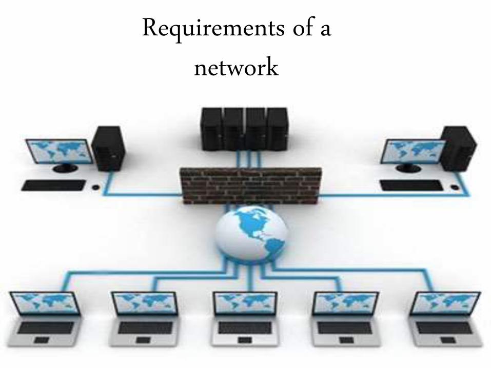
Requirements of a network

Requirements of a Network
• It is based on various aspects mentioned below
1. Perspectives
2. Scalable connectivity
3. Cost effective resource sharing
4. Support for common services
5. Reliability
6. Manageability
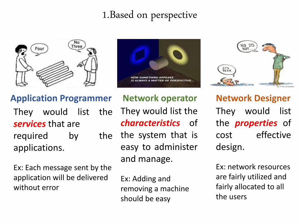
1.Based on perspective
Application Programmer Network DesignerNetwork operator
They would list theservices that arerequired by theapplications.
Ex: Each message sent by the application will be delivered without error
They would list thecharacteristics ofthe system that iseasy to administerand manage.
Ex: Adding and removing a machine should be easy
They would listthe properties ofcost effectivedesign.
Ex: network resources are fairly utilized and fairly allocated to all the users
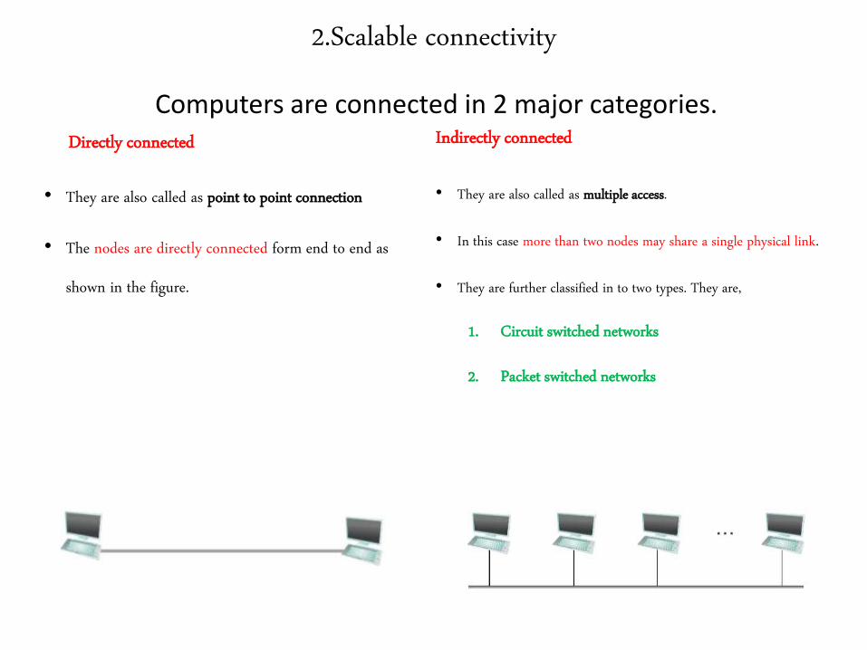
2.Scalable connectivity
Directly connected
• They are also called as point to point connection
• The nodes are directly connected form end to end as
shown in the figure.
Indirectly connected
• They are also called as multiple access.
• In this case more than two nodes may share a single physical link.
• They are further classified in to two types. They are,
1. Circuit switched networks
2. Packet switched networks
Computers are connected in 2 major categories.
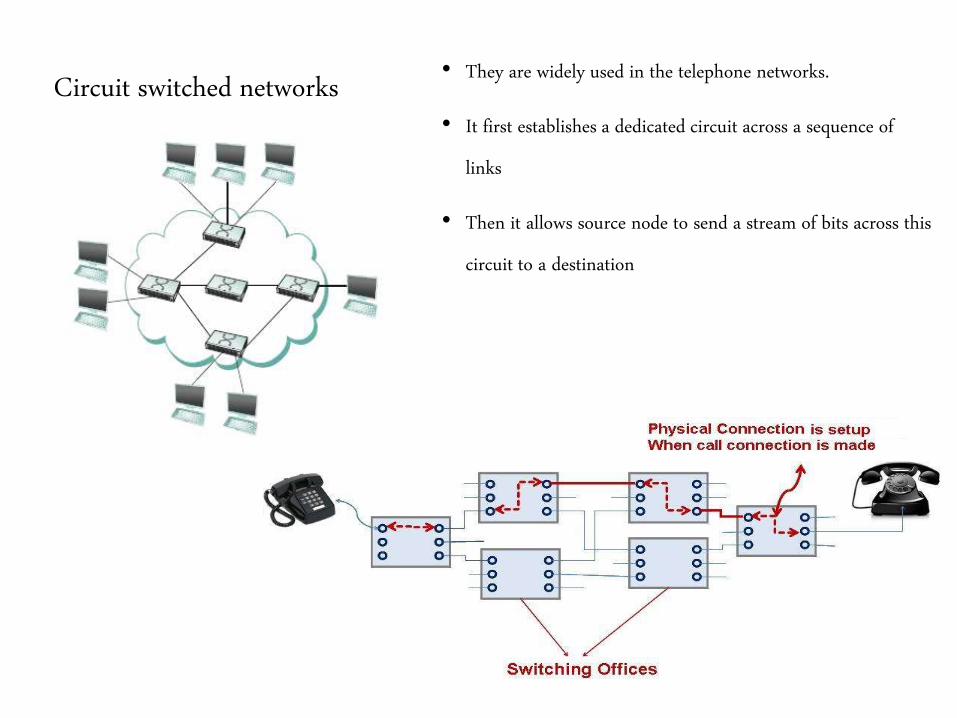
Circuit switched networks• They are widely used in the telephone networks.
• It first establishes a dedicated circuit across a sequence of
links
• Then it allows source node to send a stream of bits across this
circuit to a destination
Packet switched networks
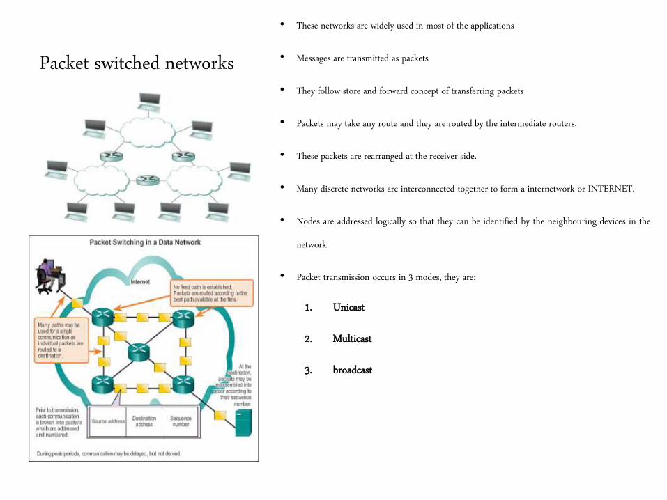
• These networks are widely used in most of the applications
• Messages are transmitted as packets
• They follow store and forward concept of transferring packets
• Packets may take any route and they are routed by the intermediate routers.
• These packets are rearranged at the receiver side.
• Many discrete networks are interconnected together to form a internetwork or INTERNET.
• Nodes are addressed logically so that they can be identified by the neighbouring devices in the
network
• Packet transmission occurs in 3 modes, they are:
1. Unicast
2. Multicast
3. broadcast
3.Cost Effective Resource Sharing
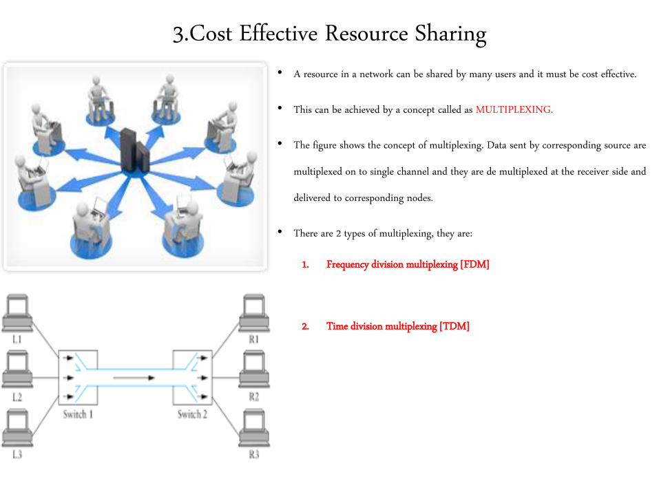
• A resource in a network can be shared by many users and it must be cost effective.
• This can be achieved by a concept called as MULTIPLEXING.
• The figure shows the concept of multiplexing. Data sent by corresponding source are
multiplexed on to single channel and they are de multiplexed at the receiver side and
delivered to corresponding nodes.
• There are 2 types of multiplexing, they are:
1. Frequency division multiplexing [FDM]
2. Time division multiplexing [TDM]
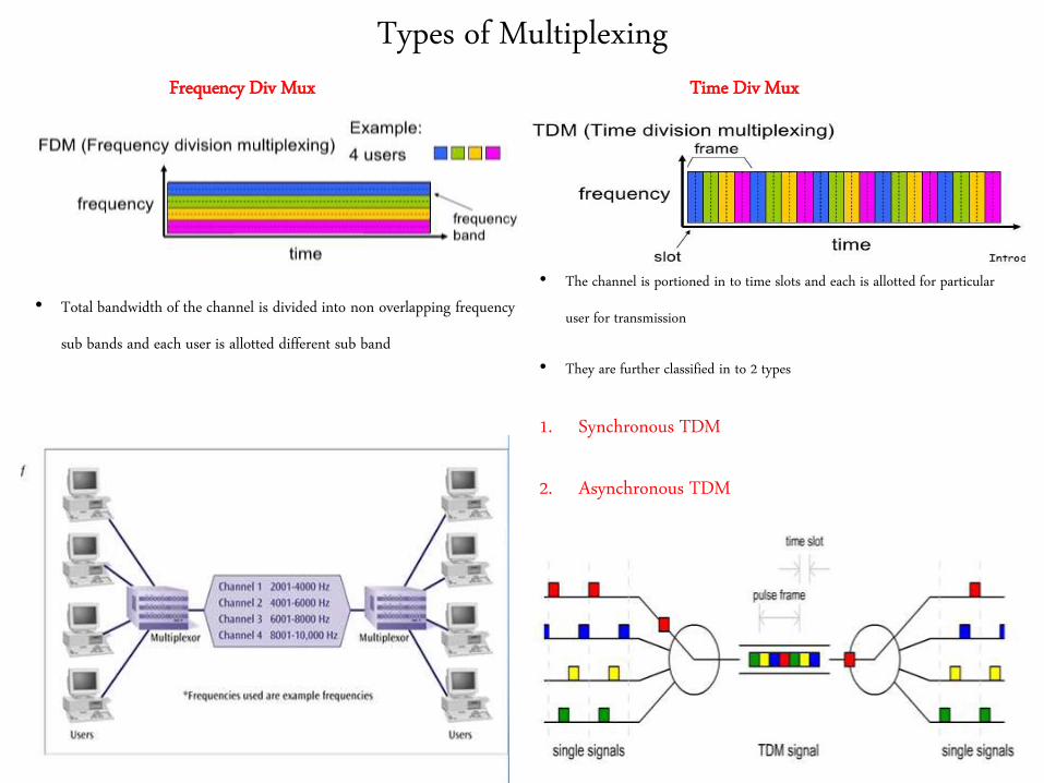
Types of MultiplexingFrequency Div Mux
• Total bandwidth of the channel is divided into non overlapping frequency
sub bands and each user is allotted different sub band
Time Div Mux
• The channel is portioned in to time slots and each is allotted for particular
user for transmission
• They are further classified in to 2 types
1. Synchronous TDM
2. Asynchronous TDM
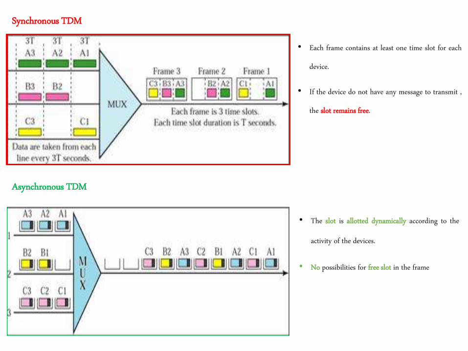
Synchronous TDM
• Each frame contains at least one time slot for each
device.
• If the device do not have any message to transmit ,
the slot remains free.
Asynchronous TDM
• The slot is allotted dynamically according to the
activity of the devices.
• No possibilities for free slot in the frame
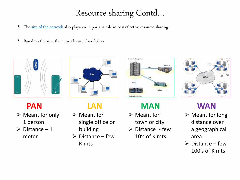
Resource sharing Contd…• The size of the network also plays an important role in cost effective resource sharing.
• Based on the size, the networks are classified as
PAN LAN MAN WAN Meant for only
1 person Distance – 1
meter
Meant for single office or building
Distance – few K mts
Meant for town or city
Distance - few 10’s of K mts
Meant for long distance over a geographical area
Distance – few 100’s of K mts
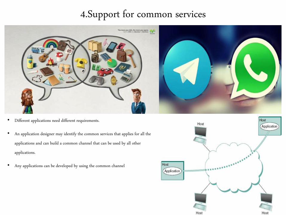
4.Support for common services
• Different applications need different requirements.
• An application designer may identify the common services that applies for all the
applications and can build a common channel that can be used by all other
applications.
• Any applications can be developed by using the common channel
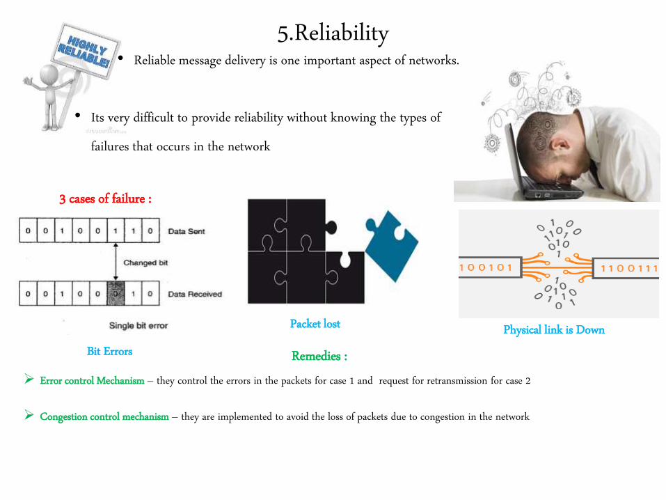
• Its very difficult to provide reliability without knowing the types of
failures that occurs in the network
5.Reliability• Reliable message delivery is one important aspect of networks.
3 cases of failure :
Remedies :Bit Errors
Packet lost Physical link is Down
Error control Mechanism – they control the errors in the packets for case 1 and request for retransmission for case 2
Congestion control mechanism – they are implemented to avoid the loss of packets due to congestion in the network
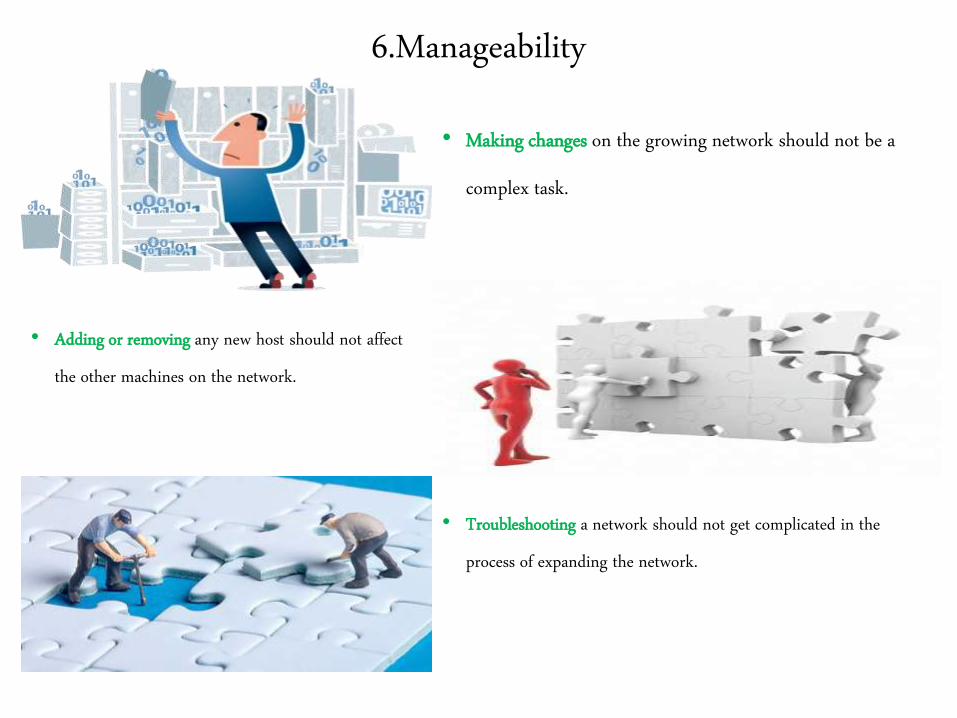
6.Manageability
• Making changes on the growing network should not be a
complex task.
• Adding or removing any new host should not affect
the other machines on the network.
• Troubleshooting a network should not get complicated in the
process of expanding the network.
Final Verdict
• Thus a computer network must provide a general, cost effective, fair and robust
connectivity among the group of computers.
• It must also deal with the varying environments to adopt the changes and latest
technologies.
• They must be manageable by any humans with varying skill sets.
End of
Requirements

Network Architecture
Network Architecture
• Building a network with all the pre discussed requirements is not an easy job.
• To get rid of this complexity the networks are given some architecture. They
are referred to as Blue Prints.
• There are 2 most widely used network architectures. They are as follows
1. OSI Architecture
2. Internet Architecture
Features of Architectures
• The architectural design provides 2 main features, they are:
It decomposes the problem of building a network into more components
- Several layers are added and each is assigned with different functionality.
It provides a more modular design
- Making modifications becomes easier.
- If any new services wanted to be added , then the modifications can be done only at 1 respective
layer. Other layers can be reused as such
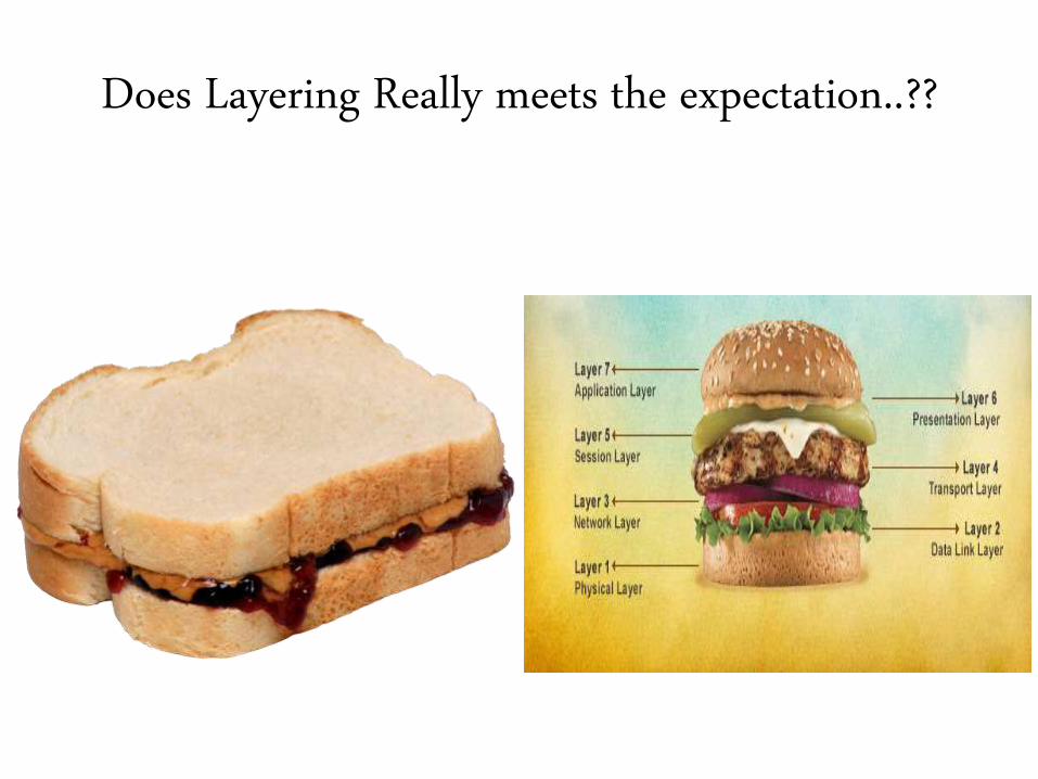
Does Layering Really meets the expectation..??
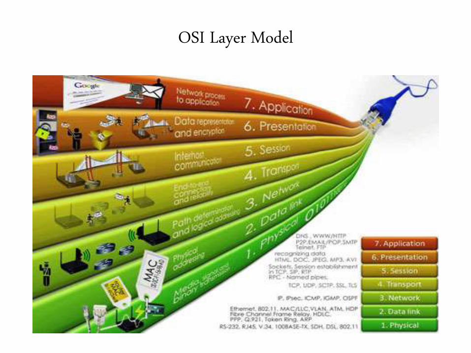
OSI Layer Model
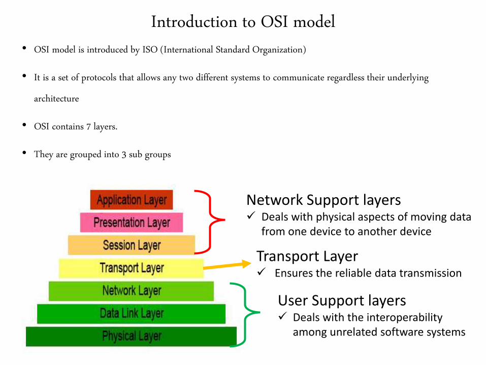
Introduction to OSI model• OSI model is introduced by ISO (International Standard Organization)
• It is a set of protocols that allows any two different systems to communicate regardless their underlying
architecture
• OSI contains 7 layers.
• They are grouped into 3 sub groups
Network Support layers Deals with physical aspects of moving data
from one device to another device
User Support layers Deals with the interoperability
among unrelated software systems
Transport Layer Ensures the reliable data transmission
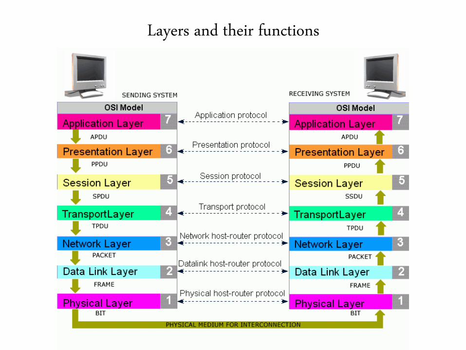
Layers and their functions
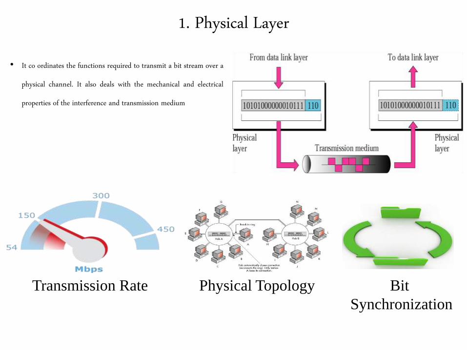
1. Physical Layer
• It co ordinates the functions required to transmit a bit stream over a
physical channel. It also deals with the mechanical and electrical
properties of the interference and transmission medium
Transmission Rate Bit
Synchronization
Physical Topology
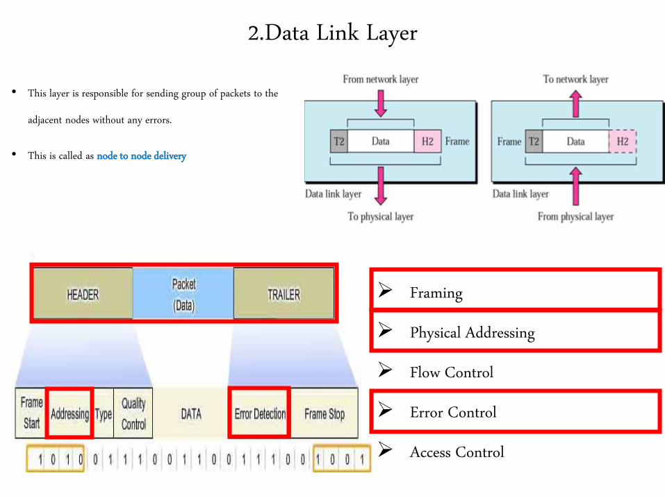
2.Data Link Layer
• This layer is responsible for sending group of packets to the
adjacent nodes without any errors.
• This is called as node to node delivery
Framing
Physical Addressing
Flow Control
Error Control
Access Control
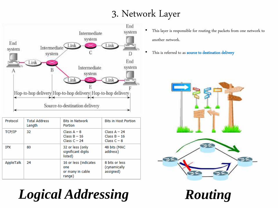
3. Network Layer
• This layer is responsible for routing the packets from one network to
another network.
• This is referred to as source to destination delivery
Logical Addressing Routing
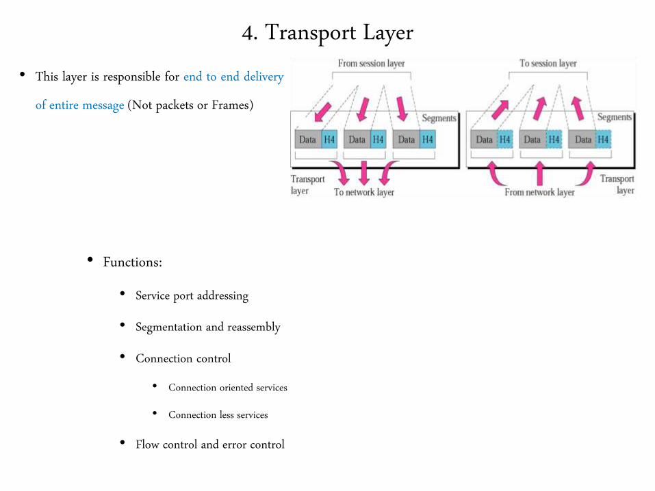
4. Transport Layer
• This layer is responsible for end to end delivery
of entire message (Not packets or Frames)
• Functions:
• Service port addressing
• Segmentation and reassembly
• Connection control
• Connection oriented services
• Connection less services
• Flow control and error control
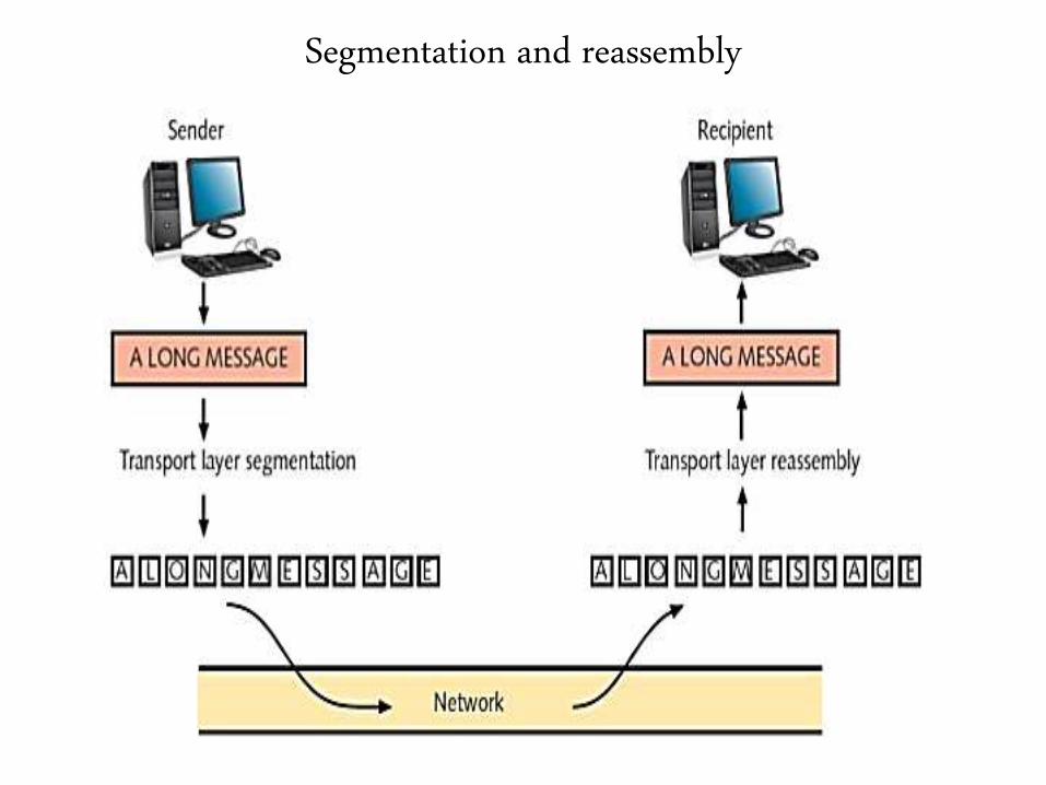
Segmentation and reassembly

Service Port addressing
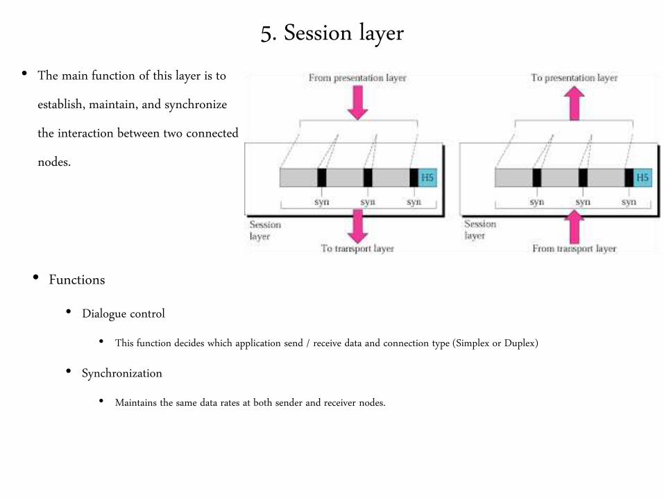
5. Session layer
• The main function of this layer is to
establish, maintain, and synchronize
the interaction between two connected
nodes.
• Functions
• Dialogue control
• This function decides which application send / receive data and connection type (Simplex or Duplex)
• Synchronization
• Maintains the same data rates at both sender and receiver nodes.
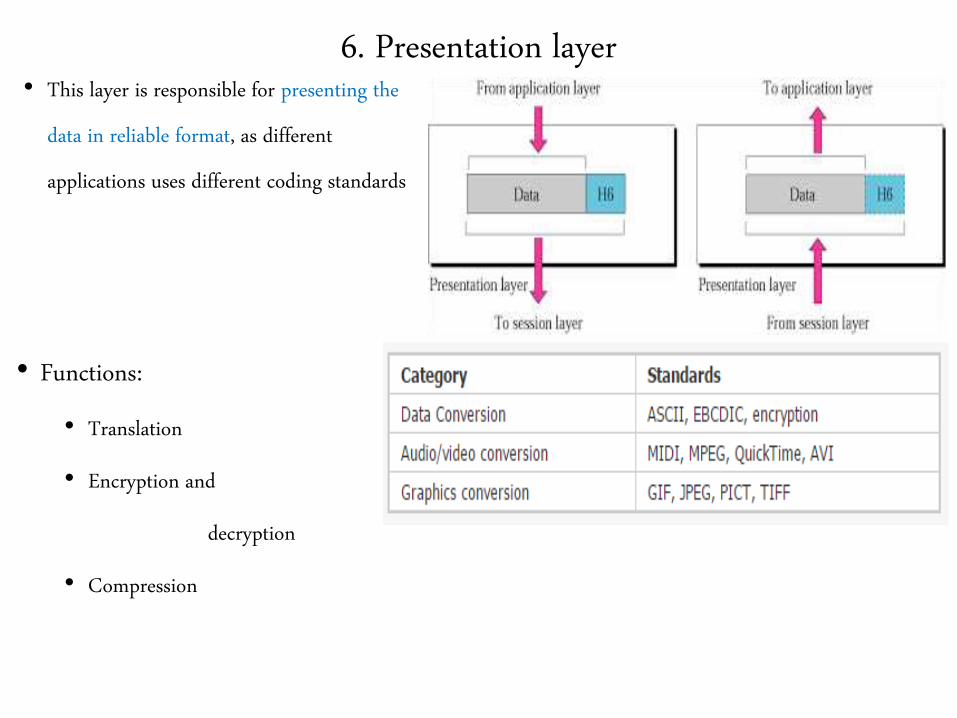
6. Presentation layer• This layer is responsible for presenting the
data in reliable format, as different
applications uses different coding standards
• Functions:
• Translation
• Encryption and
decryption
• Compression
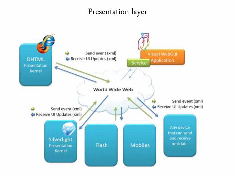
Presentation layer
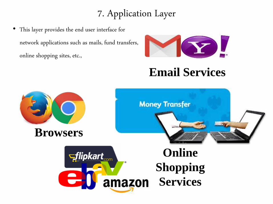
7. Application Layer
• This layer provides the end user interface for
network applications such as mails, fund transfers,
online shopping sites, etc.,
Email Services
Browsers
Online
Shopping
Services

End of
OSI Model

Internet Architecture
Internet Architecture
• They are also called as TCP / IP Architecture or TCP / IP Protocol Suite.
• This model uses various protocols at different layers. They are discussed
in up coming slides.
TCP / IP Protocol suite
1. Network interface layer
• The physical and datalink layer of the OSI model are jointly known as Network
Interface layer in TCP / IP Model
• There is no specific protocols in this layers and they supports all standards
• They particularly deals with the physical connection between the nodes

2. Network Layer
• They are also called as Internet layer.
• This layer defines the official packet format.
• Protocol used is Internet Protocol (IP)
• They are responsible for successful delivery of packets from one host to
another host
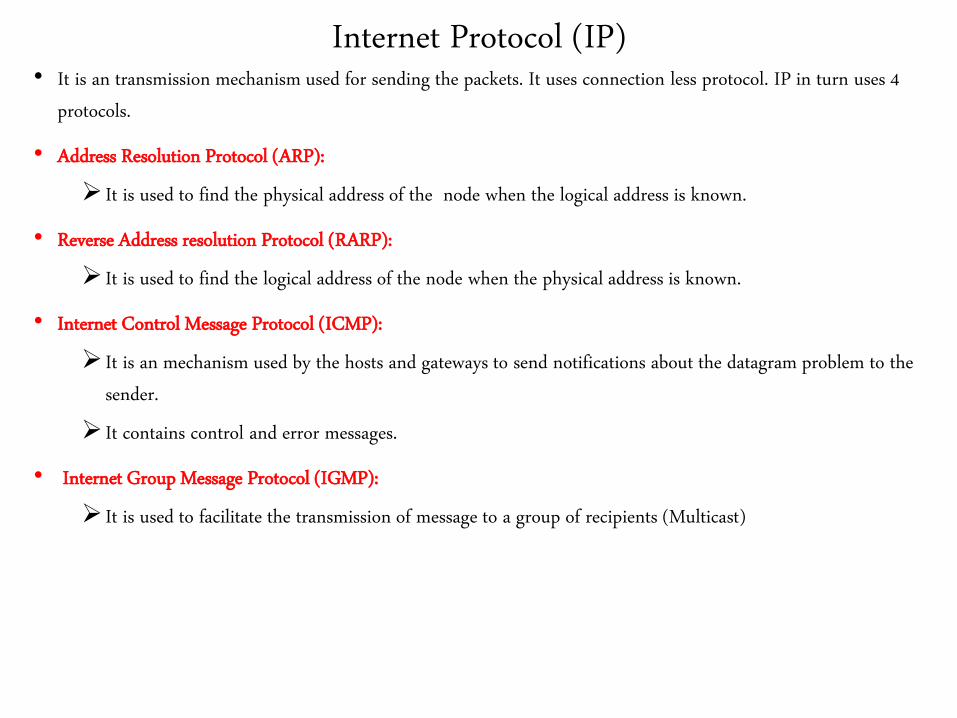
Internet Protocol (IP)• It is an transmission mechanism used for sending the packets. It uses connection less protocol. IP in turn uses 4
protocols.
• Address Resolution Protocol (ARP):
It is used to find the physical address of the node when the logical address is known.
• Reverse Address resolution Protocol (RARP):
It is used to find the logical address of the node when the physical address is known.
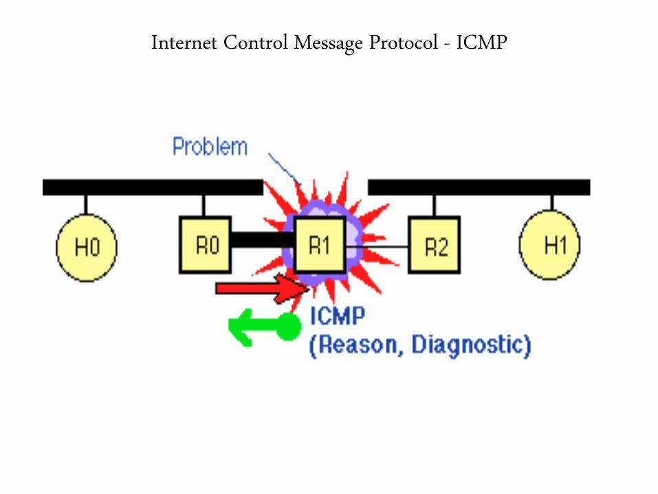
• Internet Control Message Protocol (ICMP):
It is an mechanism used by the hosts and gateways to send notifications about the datagram problem to the
sender.
It contains control and error messages.
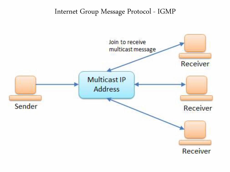
• Internet Group Message Protocol (IGMP):
It is used to facilitate the transmission of message to a group of recipients (Multicast)
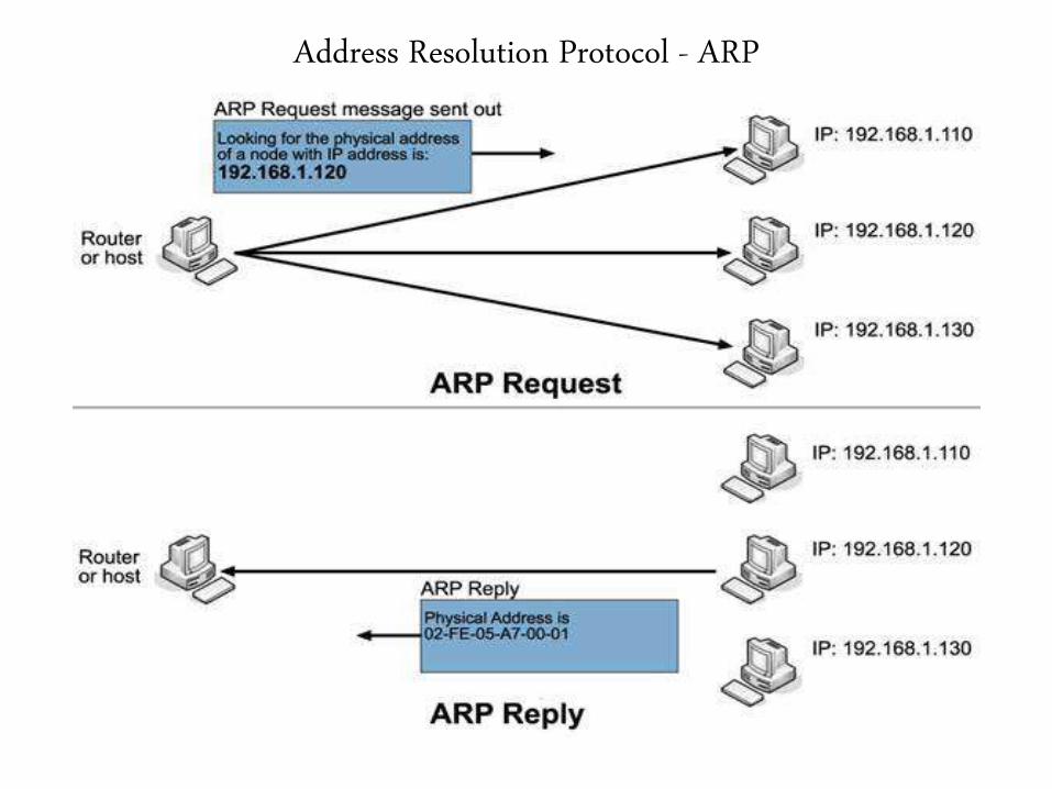
Address Resolution Protocol - ARP
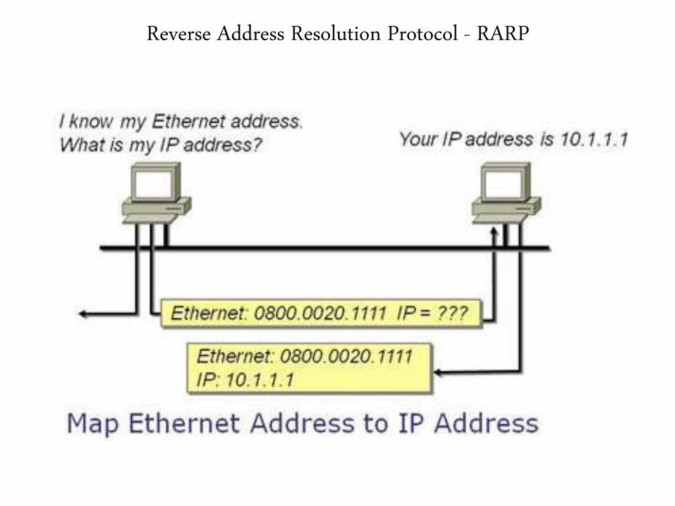
Reverse Address Resolution Protocol - RARP
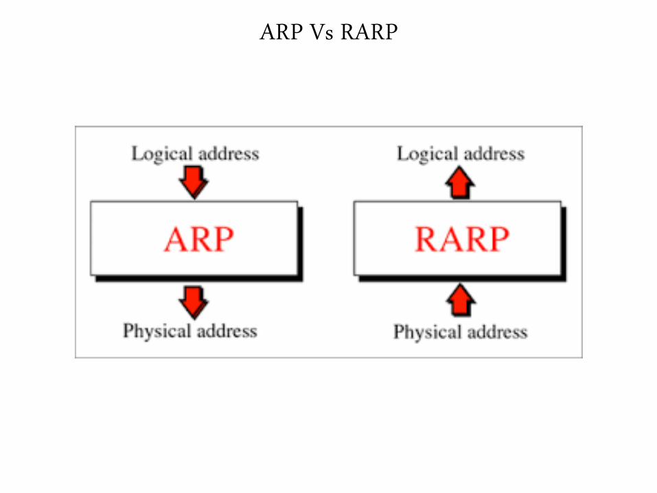
ARP Vs RARP
Internet Control Message Protocol - ICMP
Internet Group Message Protocol - IGMP
3. Transport layer
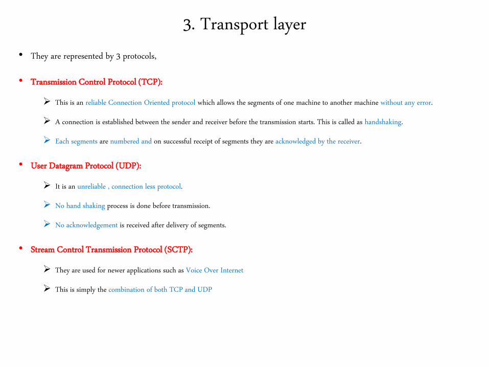
• They are represented by 3 protocols,
• Transmission Control Protocol (TCP):
This is an reliable Connection Oriented protocol which allows the segments of one machine to another machine without any error.
A connection is established between the sender and receiver before the transmission starts. This is called as handshaking.
Each segments are numbered and on successful receipt of segments they are acknowledged by the receiver.
• User Datagram Protocol (UDP):
It is an unreliable , connection less protocol.
No hand shaking process is done before transmission.
No acknowledgement is received after delivery of segments.
• Stream Control Transmission Protocol (SCTP):
They are used for newer applications such as Voice Over Internet
This is simply the combination of both TCP and UDP
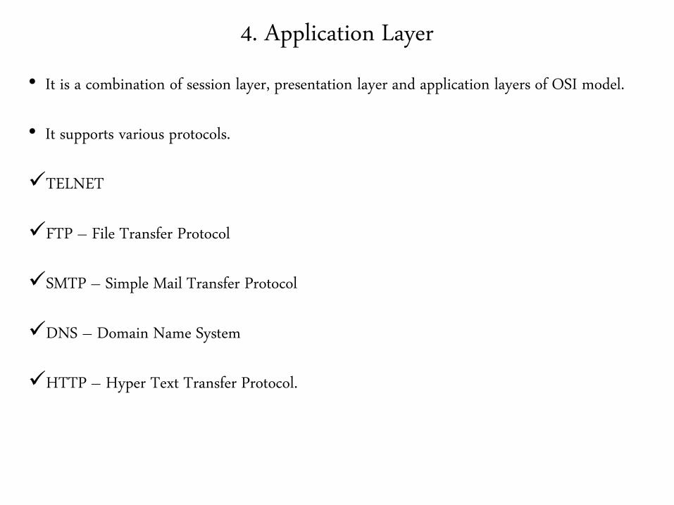
4. Application Layer
• It is a combination of session layer, presentation layer and application layers of OSI model.
• It supports various protocols.
TELNET
FTP – File Transfer Protocol
SMTP – Simple Mail Transfer Protocol
DNS – Domain Name System
HTTP – Hyper Text Transfer Protocol.
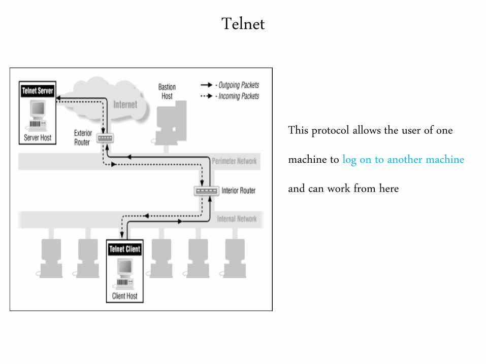
Telnet
This protocol allows the user of one
machine to log on to another machine
and can work from here
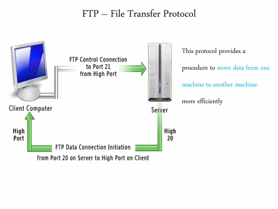
FTP – File Transfer Protocol
This protocol provides a
procedure to move data from one
machine to another machine
more efficiently
SMTP – Simple Mail Transfer Protocol
This protocol is mainly used for mail
transfers from various servers.

DNS – Domain Name System
This protocol is helpful in
mapping their host name with
their network address
HTTP – Hyper Text Transfer Protocol
This protocol is used in fetching the
webpages on the world wide web
and other functionalities as well
End of TCP / IP Model
&End of
Network Architecture
Network Performance
Network Performance
• One important aspect of a network is to measure How good it is?..
• This is referred to as network performance.
• There are 4 major performance measuring parameters.
Bandwidth
Throughput
Latency
Bandwidth and delay product
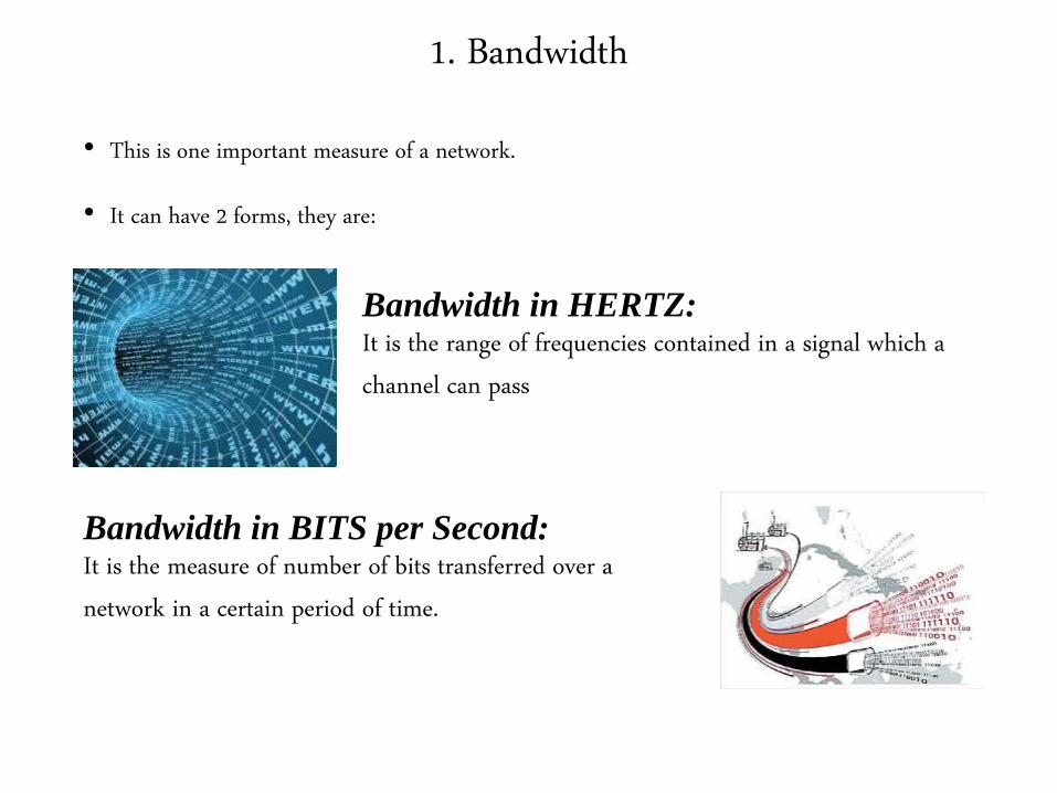
1. Bandwidth
• This is one important measure of a network.
• It can have 2 forms, they are:
Bandwidth in HERTZ:It is the range of frequencies contained in a signal which a
channel can pass
Bandwidth in BITS per Second:It is the measure of number of bits transferred over a
network in a certain period of time.
2. Throughput
• Throughput is the rate of successful message delivery over a communication
channel.
• This decides how fast we can send the data.
• A link may have bandwidth of “B” bits per second but we can transmit only “T”
bits per second trough this link.
• Where T is always less than B.
• A link may be a 1Mbps Line but we can send data only at the speed of 200Kbps.
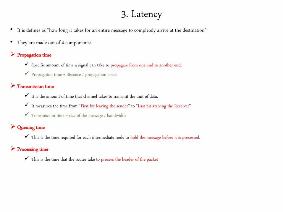
3. Latency • It is defines as “how long it takes for an entire message to completely arrive at the destination”
• They are made out of 4 components:
Propagation time
Specific amount of time a signal can take to propagate from one end to another end.
Propagation time = distance / propagation speed
Transmission time
It is the amount of time that channel takes to transmit the unit of data.
It measures the time from “First bit leaving the sender” to “Last bit arriving the Receiver”
Transmission time = size of the message / bandwidth
Queuing time
This is the time required for each intermediate node to hold the message before it is processed.
Processing time
This is the time that the router take to process the header of the packet
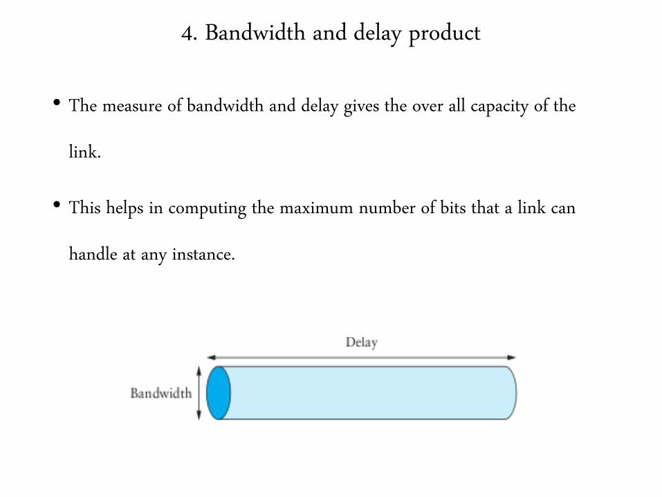
4. Bandwidth and delay product
• The measure of bandwidth and delay gives the over all capacity of the
link.
• This helps in computing the maximum number of bits that a link can
handle at any instance.
End of
Network Performance

Link Layer Services
Link Layer Services
• The main functions of data link layer are as follows,
1. Framing
2. Flow control
3. Error control
4. Error detection
1. Framing
• It is the process in which the packets received from the network layer are
divided into smaller parts called as frames.
• There are 2 types of framing
Fixed length framing.
Variable length framing.
• The challenging task is to identify the start and end of the frame.
Fixed length framing
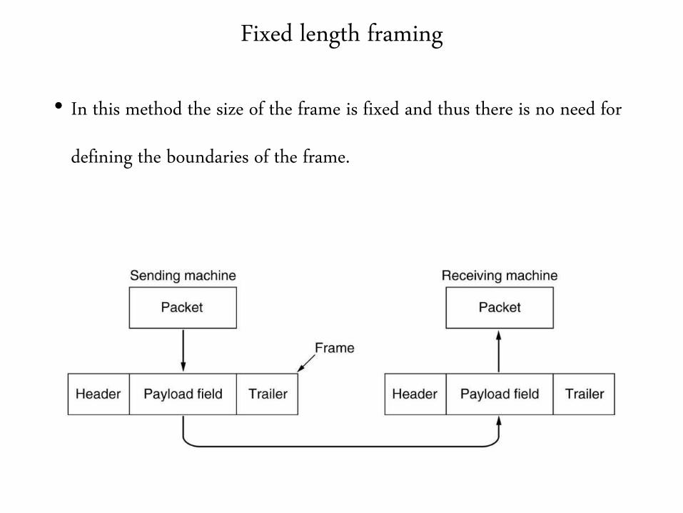
• In this method the size of the frame is fixed and thus there is no need for
defining the boundaries of the frame.
Variable Length Framing
• The size of the frame is not fixed. (Varies).
• Hence we need a way to define the frame boundaries.
• There are 3 approaches
Byte oriented framing
Bit oriented framing
Clock based framing

Byte Oriented Framing
• Normally the frame from the upper layer comes with the header and trailer information .
• Header contains source and destination address
• Trailer contains error detection and correction information
• In order to identify the frame boundaries an 8 bit flag is added at both the ends
• These flag may contain protocol dependent special characters.
Problems with Flags
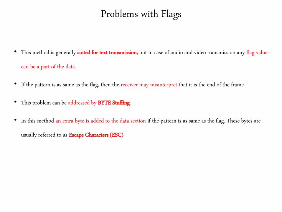
• This method is generally suited for text transmission, but in case of audio and video transmission any flag value
can be a part of the data.
• If the pattern is as same as the flag, then the receiver may misinterpret that it is the end of the frame
• This problem can be addressed by BYTE Stuffing.
• In this method an extra byte is added to the data section if the pattern is as same as the flag. These bytes are
usually referred to as Escape Characters (ESC)
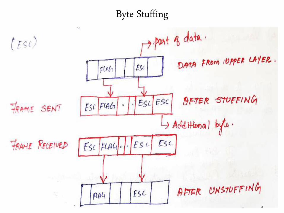
Byte Stuffing

Example for Byte Stuffing
• The universal codes that we use now a days may conflict with the 8 bit
characters of the flag.
• The Protocols that uses this approach are BISYNC, PPP, DDCMP Etc.,
• Hence we move towards an another approach called as Bit stuffing.
Bit Oriented Framing
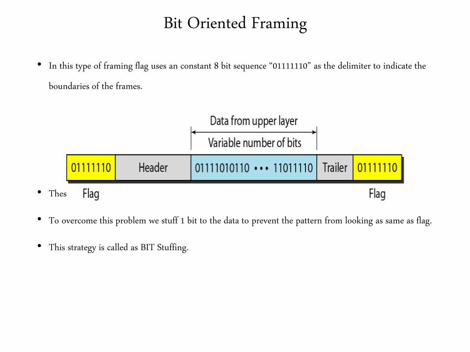
• In this type of framing flag uses an constant 8 bit sequence “01111110” as the delimiter to indicate the
boundaries of the frames.
• These flags may also create the same problem as Byte oriented protocols.
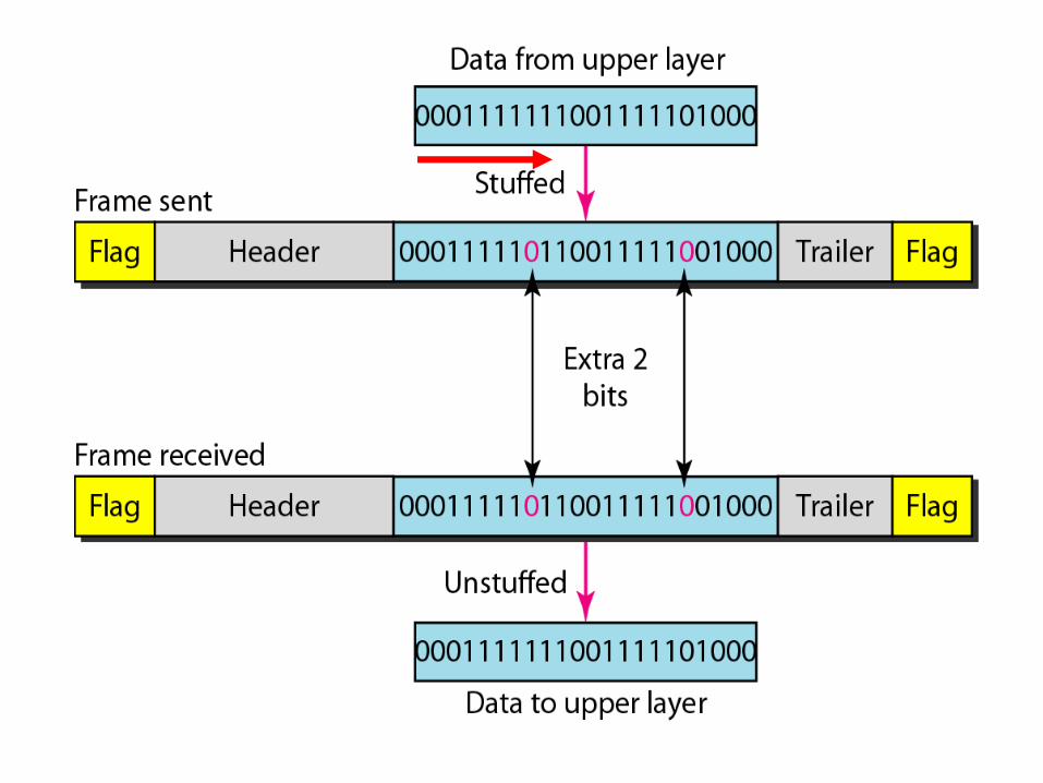
• To overcome this problem we stuff 1 bit to the data to prevent the pattern from looking as same as flag.
• This strategy is called as BIT Stuffing.
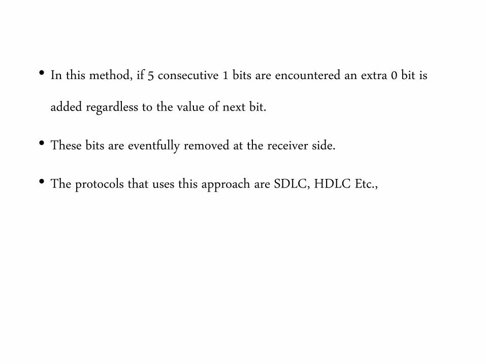
• In this method, if 5 consecutive 1 bits are encountered an extra 0 bit is
added regardless to the value of next bit.
• These bits are eventfully removed at the receiver side.
• The protocols that uses this approach are SDLC, HDLC Etc.,
Clock Based Framing
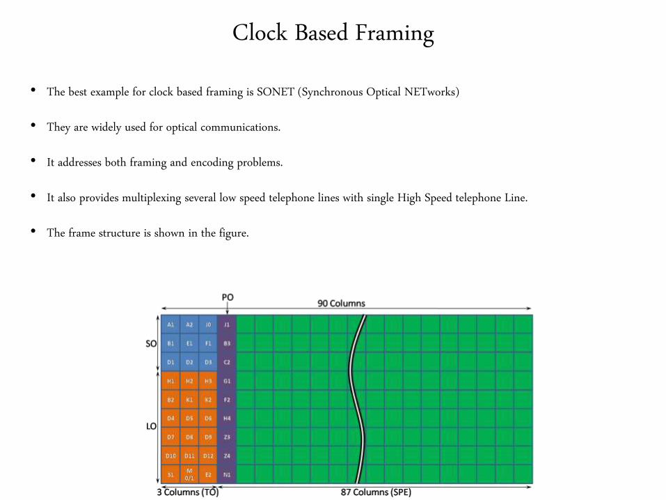
• The best example for clock based framing is SONET (Synchronous Optical NETworks)
• They are widely used for optical communications.
• It addresses both framing and encoding problems.
• It also provides multiplexing several low speed telephone lines with single High Speed telephone Line.
• The frame structure is shown in the figure.
• It contains 9 rows of 90 bytes each
• First 3 bytes of each row is overhead and the rest is available for data
• The first 2 bytes of each frame contains the special bit pattern and these pattern are used for
determining the start and stop of the frame by the receiver.
• The receiver checks for this bit pattern once in every 810 bytes (9*90 = 810 bytes)
• The overhead bytes are encoded using NRZ and the bit pattern is scrambled.
• Scrambling is done by ExOR ing the data bits with well known bit patterns.

End of
Framing
2. Flow Control
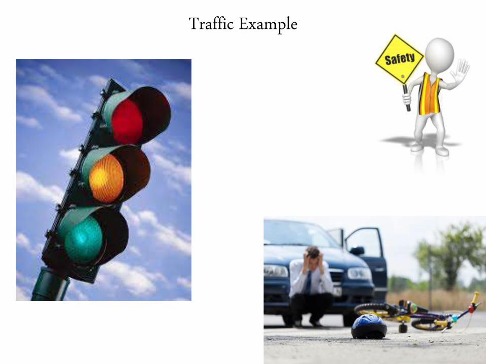
Traffic Example
Flow Control
• It co ordinates the amount of data that can be sent before receiving and
acknowledgement.
• They are widely used in the synchronizing purpose. At any case the flow of
transmitter should not overwhelm the flow of receiver.
• The two main protocols that are used for flow control are
Stop and wait Protocol
Sliding window Protocol
Stop and Wait Protocol
• This is used for sending one frame at a time.
• They are simple and easy to implement
• This protocol sends one frame at a time and waits for the acknowledgement (ACK)
from the receiver.
• Next frame is sent only if receiver acknowledges the previous frame. If ACK is not
received then the transmission is stopped temporarily.
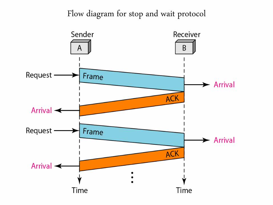
Flow diagram for stop and wait protocol
Merits and Demerits
• Merits
• Each frame is acknowledged individually
• No loss of frames during transmission
• Demerits
• Very inefficient
• Transmission is very slow.
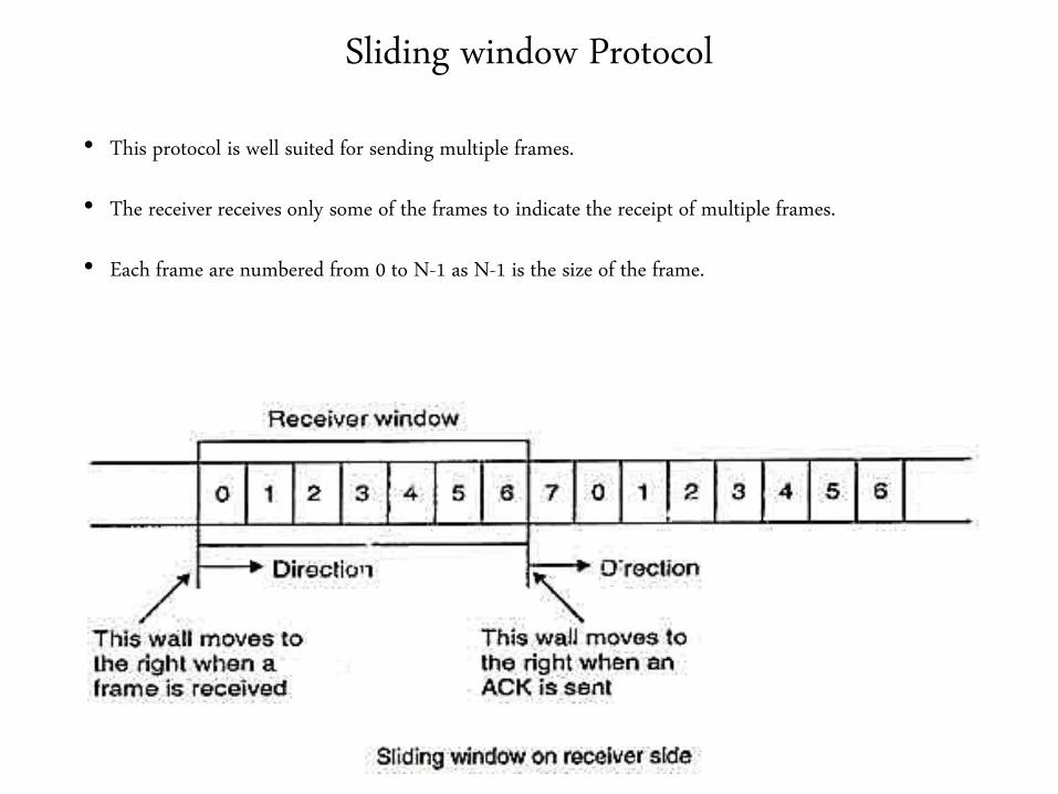
Sliding window Protocol
• This protocol is well suited for sending multiple frames.
• The receiver receives only some of the frames to indicate the receipt of multiple frames.
• Each frame are numbered from 0 to N-1 as N-1 is the size of the frame.
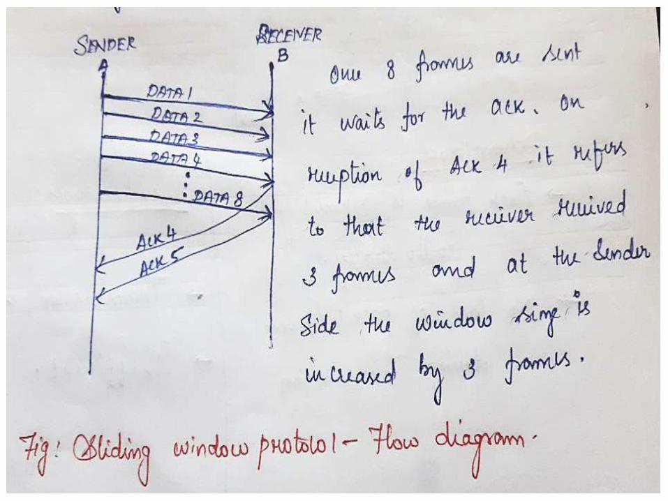

Sliding window form Sender and Receiver Prespective
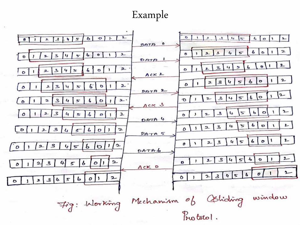
Example

End of
Flow Control

3. Error Control
Error Control
• Most of the channels used in the real time communications are noisy channels
• These noise in the channel causes errors in the passing data.
• Thus a special mechanism is required to control these errors.
• Error control Protocols are categorised as
Stop and wait ARQ
Sliding window ARQ
Go back n ARQ
Selective Repeat ARQ (Selective Reject ARQ)
Stop and Wait ARQ
• ARQ – Automatic Repeat Request
• This protocol adds simple errorcontrol mechanism to ordinary stop and wait protocol.
• After transmitting one frame the sender waits for an acknowledgement before sending the next packet.
• If the ACK is not received within a predefined time period then the frame is retransmitted by the sender.
• Various scenarios,
Frame delivered , ACK received on time.
Frame delivered, ACK is lost
Frame is lost
Frame Delivered , ACK Received after Time out.
Flow Diagram for different scenarios
Drawback
• The major draw back in the stop and wait ARQ is that, in case (b) and (d) the frame is
retransmitted even though the first frame is delivered successfully.
• This creates duplicate copies of frames at the receiving side.
• This can be overcome by adding sequence numbers to the frames and acknowledgements.
• By this the receiver could identify either the frame is duplicated frame or Original frame.
Sliding window ARQ
• These protocols are designed to transmit multiple frames at a time.
• They are further classified into 2 types,
Go Back n ARQ
Selective Repeat ARQ
Go Back n ARQ
• In order to improve the channel efficiency multiple frames are transmitted and a copy
is retained until they are acknowledged.
• The different scenarios are,
Damaged frame
Lost frame
Lost ACK
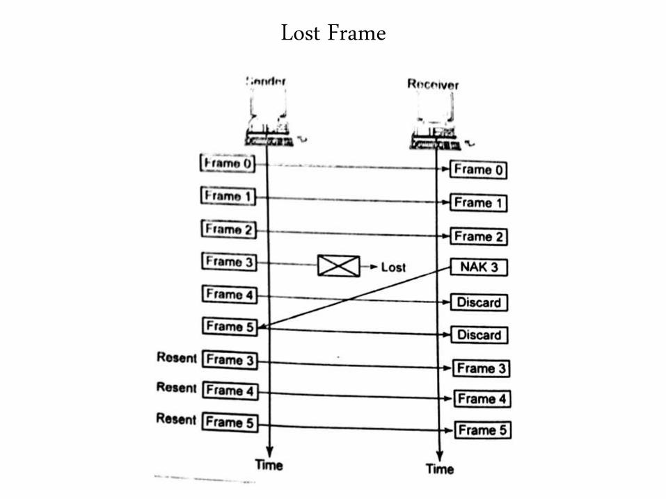
Lost Frame
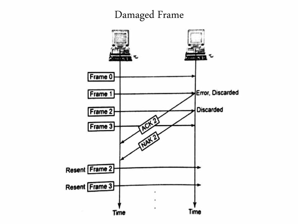
Damaged Frame
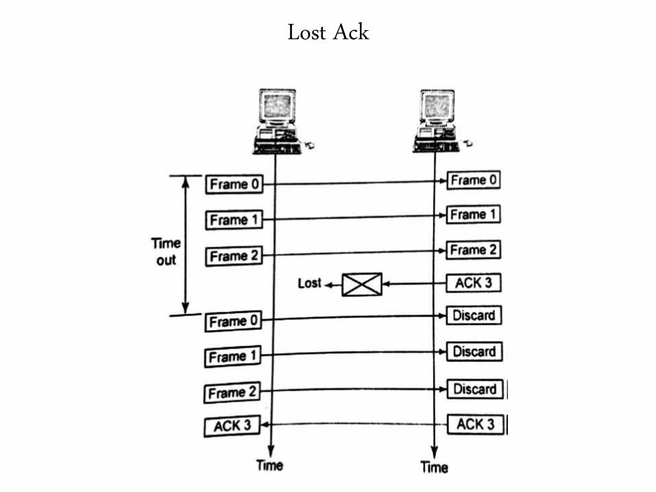
Lost Ack
Drawback of Go Back n ARQ
• In case of lost frame or lost ack all the frames are retransmitted, which again
creates the duplication of frames at the receiver side.
• Hence to overcome this we go for another type called as Selective Repeat ARQ.
Selective Repeat ARQ
• In this protocol only the specific damaged or lost frames are retransmitted.
• This protocol can re arrange the sequence of frames at the receiver based on the
sequence numbers.
• The flow diagram for various cases are shown in the upcoming slides.
Damaged frame
Lost frame
Lost ACK
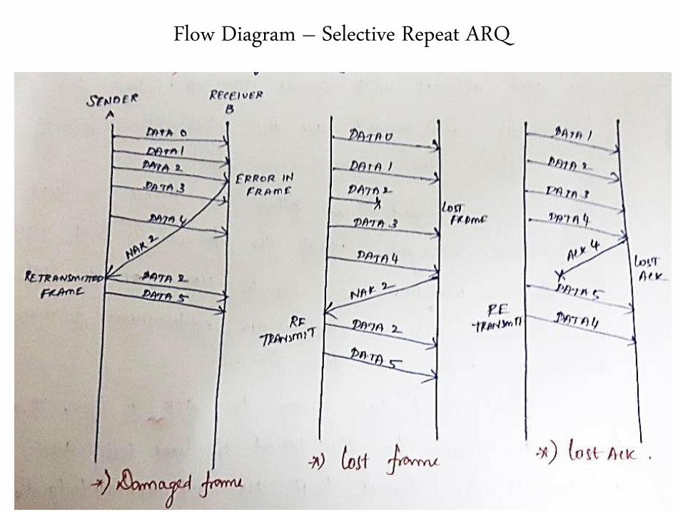
Flow Diagram – Selective Repeat ARQ
End of
Error Control
4. Error Detection
Error Detection
• For controlling the errors the errors are to be identified first.
• Errors are introduced in to the channel due to thermal noise and electrical
interference.
• We hereby discuss 3 approaches for error detection.
Two Dimensional Parity
Checksum
Cyclic Redundancy Check (CRC)
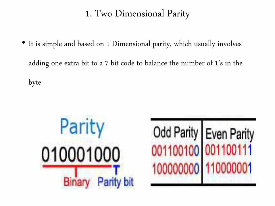
1. Two Dimensional Parity
• It is simple and based on 1 Dimensional parity, which usually involves
adding one extra bit to a 7 bit code to balance the number of 1’s in the
byte
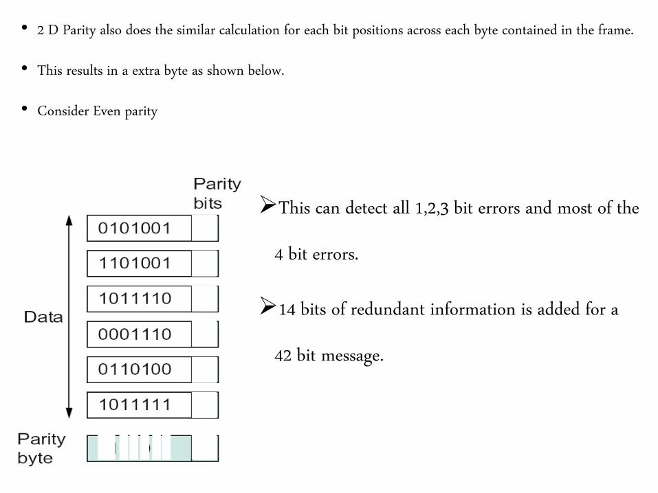
• 2 D Parity also does the similar calculation for each bit positions across each byte contained in the frame.
• This results in a extra byte as shown below.
• Consider Even parity
This can detect all 1,2,3 bit errors and most of the
4 bit errors.
14 bits of redundant information is added for a
42 bit message.
2. Checksum
• These codes are based on addition
• This method uses summing algorithm.
• The idea behind this method is add up all the words that are transmitted and then transmit
the result of that sum.
• This result is referred to as checksum.
• The receiver performs the same operation and compares the result with the checksum
transmitted.
• Based on the result the receiver identifies the presence of error.
Sender Site Algorithm
The message is divided in to 16 bit words.
The value of checksum word is set to “0”
All words including checksum are added using 1’s Complement addition
The sum is complemented to get checksum
The check sum is sent along with the data.
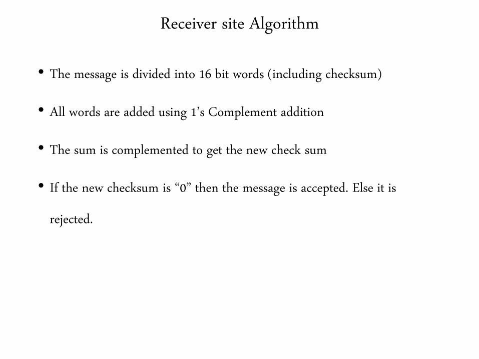
Receiver site Algorithm
• The message is divided into 16 bit words (including checksum)
• All words are added using 1’s Complement addition
• The sum is complemented to get the new check sum
• If the new checksum is “0” then the message is accepted. Else it is
rejected.
Example
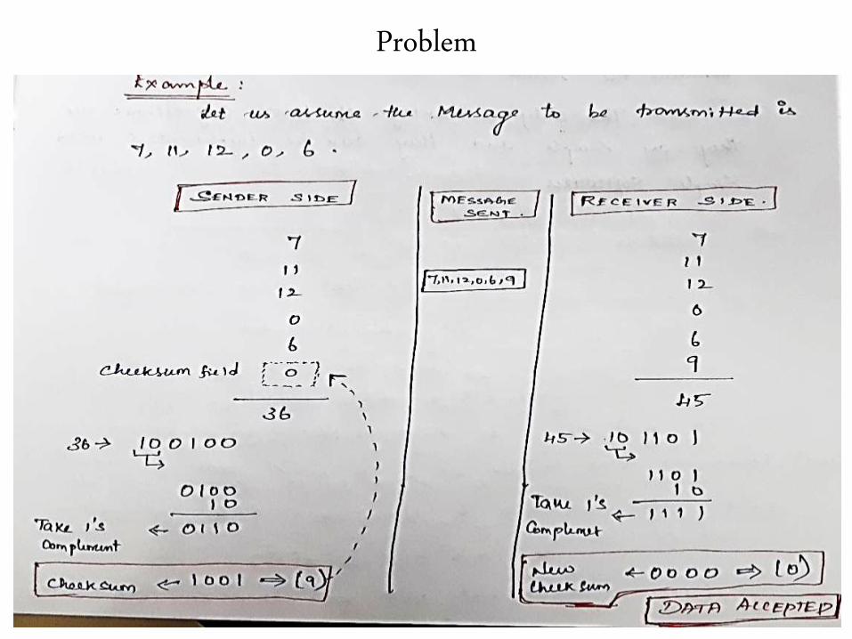
Problem
• This alg is better than the parity bits as the redundancy bits are 16 for any
length of the data
• They do not provide error detection if one bit increase by some value and
other bit reduces by the same value.
• This alg is advantageous by their simple design and easy to implement.
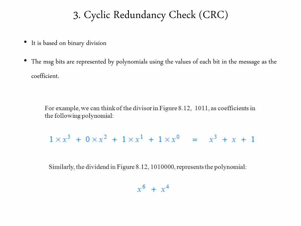
3. Cyclic Redundancy Check (CRC)
• It is based on binary division
• The msg bits are represented by polynomials using the values of each bit in the message as the
coefficient.
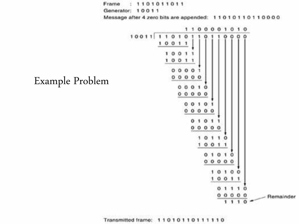
Example Problem

Versions of CRC
End of
Error Detection
End of
UNIT 1