Embed Size (px)
Citation preview

ZENSOL A U T O M A T I O N I N C .
www.zensol.com Man-1we.doc Rév 5
COMPUTERIZED TEST EQUIPMENT
ZENSOL CIRCUIT BREAKER PERFORMANCE ANALYZER
CBA-32P
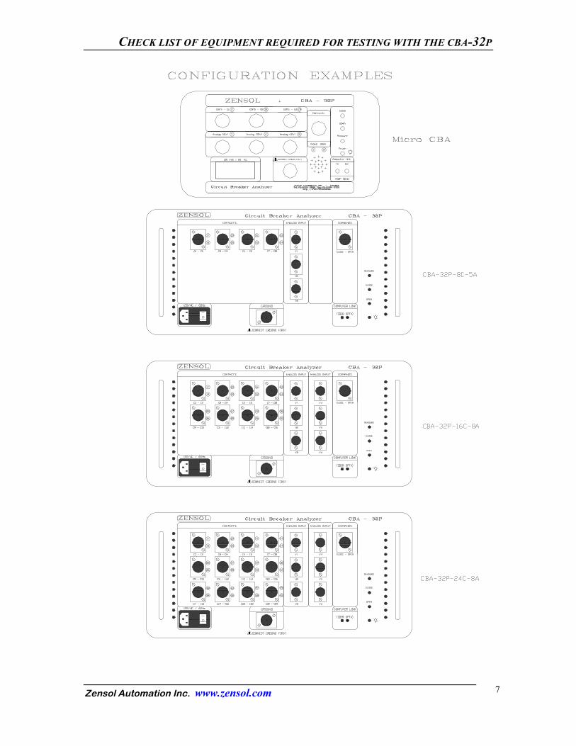
Micro CBA
MANUAL 1W E OPERATOR’S GUIDE
Version 1.70 January 2001
CBA-32 OPERATOR’S GUIDE
Zensol Automation Inc. www.zensol.com 2
TABLE OF CONTENTS OVERVIEW OF THE CBA-32P................................................................................. 3 Overview........................................................................................................... 4 Required computer............................................................................................ 4 Required printer................................................................................................ 4 Checklist of equipment required for testing with the CBA-32P................................. 5 Required equipment.......................................................................................... 5 Required cables................................................................................................. 5 Manuals............................................................................................................. 5 Additional cables required for testing with the CBA-32 in the field................ 6 Optional accessories.......................................................................................... 6 Configuration examples............................................................................................... 7 BREAKER CONNECTIONS...................................................................................... 8 Connecting the CBA-32P to the breaker........................................................... 9 Connecting ground............................................................................................ 9 Connecting power............................................................................................. 9 Connecting the personal computer.................................................................... 9 Connecting command outputs........................................................................... 11 Wiring principle for DC-DC coils......................................................... 12 Wiring principle for AC-AC coils......................................................... 13 Wiring principle for AC-DC coils......................................................... 14 Internal diagram of the CBA-32P......................................................... 15 Connecting contact inputs................................................................................. 16 Connecting linear displacement transducers..................................................... 18 Connecting other 0-10 VDC transducers.......................................................... 18 Oil breaker connections.................................................................................. 19 Testing four single-phase breakers connected in series............................... 20 Testing four three-phase breakers connected in series................................ 21 ANSWERS TO VARIOUS QUESTIONS................................................................... 22

Zensol Automation Inc. www.zensol.com 3
OVERVIEW OF THE CBA-32P
OVERVIEW OF THE CBA-32P
Zensol Automation Inc. www.zensol.com 4
OVERVIEW
The CBA-32 is a portable or desktop testing and measuring instrument that rapidly carries out timing tests on circuit breakers of all types typically installed in electric utility substations. The breakers may range from distribution level voltage models up to 800 kV environment. The CBA-32 connects to a personal computer with a color screen via a high speed optical fiber link. The computer runs the Cba Win© test software, which automates and controls the whole test procedure.
The CBA-32 is equipped with breaker command signal generators, digital inputs to measure main and resistive contact close/open states, and a number of analog inputs for measuring command coil current, linear displacement, pressure, etc.
Required computer
The following characteristics are strongly recommended for the computer running Cba Win©:
� Pentium processor and above
� Windows 95 or 98. � 16 Mb RAM minimum
� VGA monitor and graphics adapter � 3.5’’ floppy disk drive
� 1 serial port � 1 hard disk drive
Required printer
For field testing, we recommend:
� HP 340 portable printer, color and black and white.
For other purposes, any Windows-compatible printer is acceptable. Computer and Printer can be supplied with the equipment. (prices are available on request)
CHECK LIST OF EQUIPMENT REQUIRED FOR TESTING WITH THE CBA-32P
Zensol Automation Inc. www.zensol.com 5
CHECK LIST OF EQUIPMENT REQUIRED FOR TESTING WITH THE CBA-32
Required equipment
� 1 CBA-32 system with power cable � 1 computer with power cable
� Cba Win© (supplied with the equipment at no extra charge) � 1 fiber optic module (supplied with the equipment at no extra charge) including 1 RS232 to fiber optic adapter, 10’ (3 m) fiber optic cable. � 1 power bar 120VAC
Required cables
The cables described below are the Zensol 10’ (3 m) standard cables. Each of them can be fitted either with our standard clips or type car battery clips. All these cables except from the 52A and 52B cables are supplied with the CBA-32P at no extra charge.
� 1 CBA-32 ground cable
� 3, 4, 8 or 12 three-conductor 10’ contact input cables for models equipped with 8, 16 or 24 contact inputs respectively. Each cable connect to 2 breaker contacts via a wire for each and a common return � 3 or 6 three conductor 10’ displacement cables with small clips (3 for a 5 Analog model, 6 for a 6 analog model)
� 1 four conductor 25’ (7 m) command cable with clips (close, open, close, open) � 52A, 52B contact cables (optional)
Manuals
Manual 1-2-3 are supplied with the CBA-32P are no extra charge. Manual 4 comes with the internal module for dynamic contact resistance measurement. (Prices available on request- please specify when purchasing the CBA-32P) Manual 5 requires to attend one of our advanced courses: “Calculation File Designer”. (Prices and availability on request) Under CBA-Soft, the following manuals are available:
� Manual 1: Operator’s guide
� Manual 2: Installation, Analysis and test set-up guide
Under CBA-Win, the following manuals are available:
� Manual 1W – Breaker Connections
� Manual 2W – Cba Win version 1.21 user’s manual.
CHECK LIST OF EQUIPMENT REQUIRED FOR TESTING WITH THE CBA-32P
Zensol Automation Inc. www.zensol.com 6
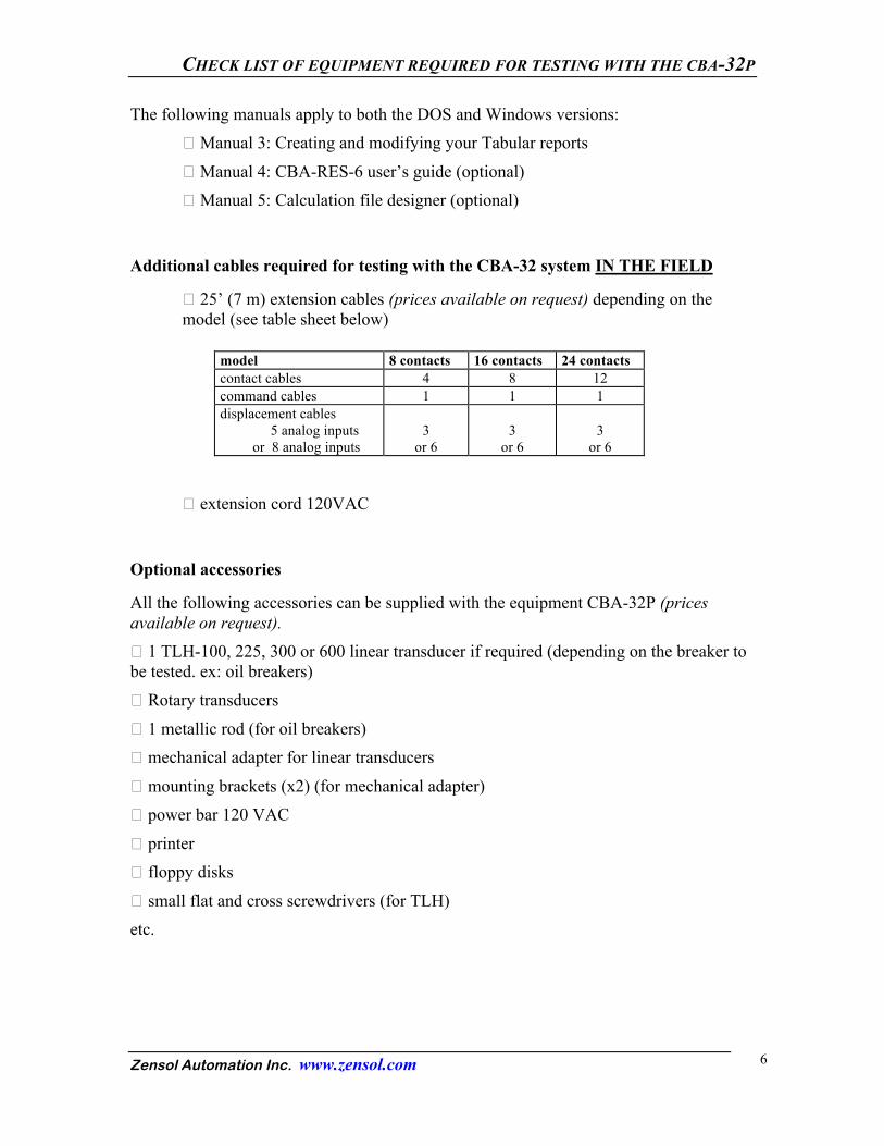
The following manuals apply to both the DOS and Windows versions: � Manual 3: Creating and modifying your Tabular reports
� Manual 4: CBA-RES-6 user’s guide (optional) � Manual 5: Calculation file designer (optional)
Additional cables required for testing with the CBA-32 system IN THE FIELD
� 25’ (7 m) extension cables (prices available on request) depending on the model (see table sheet below)
model 8 contacts 16 contacts 24 contacts contact cables 4 8 12 command cables 1 1 1 displacement cables 5 analog inputs or 8 analog inputs
3
or 6
3
or 6
3
or 6
� extension cord 120VAC
Optional accessories
All the following accessories can be supplied with the equipment CBA-32P (prices available on request). � 1 TLH-100, 225, 300 or 600 linear transducer if required (depending on the breaker to be tested. ex: oil breakers) � Rotary transducers
� 1 metallic rod (for oil breakers) � mechanical adapter for linear transducers
� mounting brackets (x2) (for mechanical adapter) � power bar 120 VAC
� printer � floppy disks
� small flat and cross screwdrivers (for TLH) etc.
CHECK LIST OF EQUIPMENT REQUIRED FOR TESTING WITH THE CBA-32P
Zensol Automation Inc. www.zensol.com 7

Zensol Automation Inc. www.zensol.com 8
BREAKER CONNECTIONS
BREAKER CONNECTIONS
Zensol Automation Inc. www.zensol.com 9
CONNECTING THE CBA-32P TO THE BREAKER
The ground, power and computer connection is illustrated on the next page.
Connecting ground
■ Connect a ground wire from the earth, building or cabinet ground to the CBA-32 input jack at the bottom center of the front panel.
High voltage environment! For your security, always make sure to work with the
CBA-32 connected to a reliable ground.
Connecting power
The CBA-32 requires 120V/60Hz power or 220V/50Hz power (please specify when ordering). A power input jack is available at the bottom left of the front panel.
■ Connect the CBA-32P to a 120VAC source with the power cable supplied.
Connecting the personal computer (see next page)
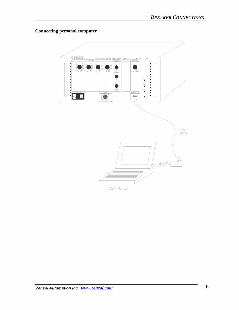
The personal computer and the Cba Win software package accompanying the CBA-32 system conducts the entire test procedure. It coordinates the acquisition of all test data. The operator may then store it on disk.
■ Connect both terminals of one end of the fiber optic cable to the front panel of the CBA-32. ■ Connect both terminals of the other end of the fiber optic cable to the RS232 to fiber optic adapter. ■ Connect the 9-pin electrical connector from the RS232 to fiber optic adapter to a free serial port on your PC.
High Speed Communication Module The High Speed Communication module is now powered by the serial port of the host computer. No external adapters are required. To connect the fiber optic cable between the CBA-32P and the Communication Module, connect the fiber optic cable marked T to the TX jacks and the cable marked R to the RX jacks on both the CBA-32P and the Communication Module.
Note to users of the externally-powered communication module: the schematic on the following page is incomplete and does not show the external 7.5 volts DC adapter required to power the module. It must be plugged into the corresponding receptacle and the polarity of the plug must be negative (-) on the center conductor and positive (+) on the outer conductor.
BREAKER CONNECTIONS
Zensol Automation Inc. www.zensol.com 10
Connecting personal computer

BREAKER CONNECTIONS
Zensol Automation Inc. www.zensol.com 11
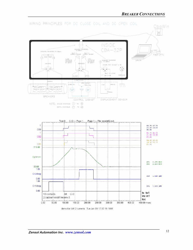
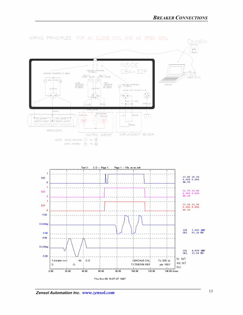
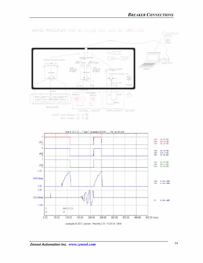
Connecting command outputs
Every breaker test requires a connection to the command coil. See the schematic examples according to your breaker controls (DC or AC).
example 1: DC, DC; example 2: AC, AC;
example 3: AC, DC.
BREAKER CONNECTIONS
Zensol Automation Inc. www.zensol.com 12
BREAKER CONNECTIONS
Zensol Automation Inc. www.zensol.com 13
BREAKER CONNECTIONS
Zensol Automation Inc. www.zensol.com 14
BREAKER CONNECTIONS
Zensol Automation Inc. www.zensol.com 15
BREAKER CONNECTIONS
Zensol Automation Inc. www.zensol.com 16
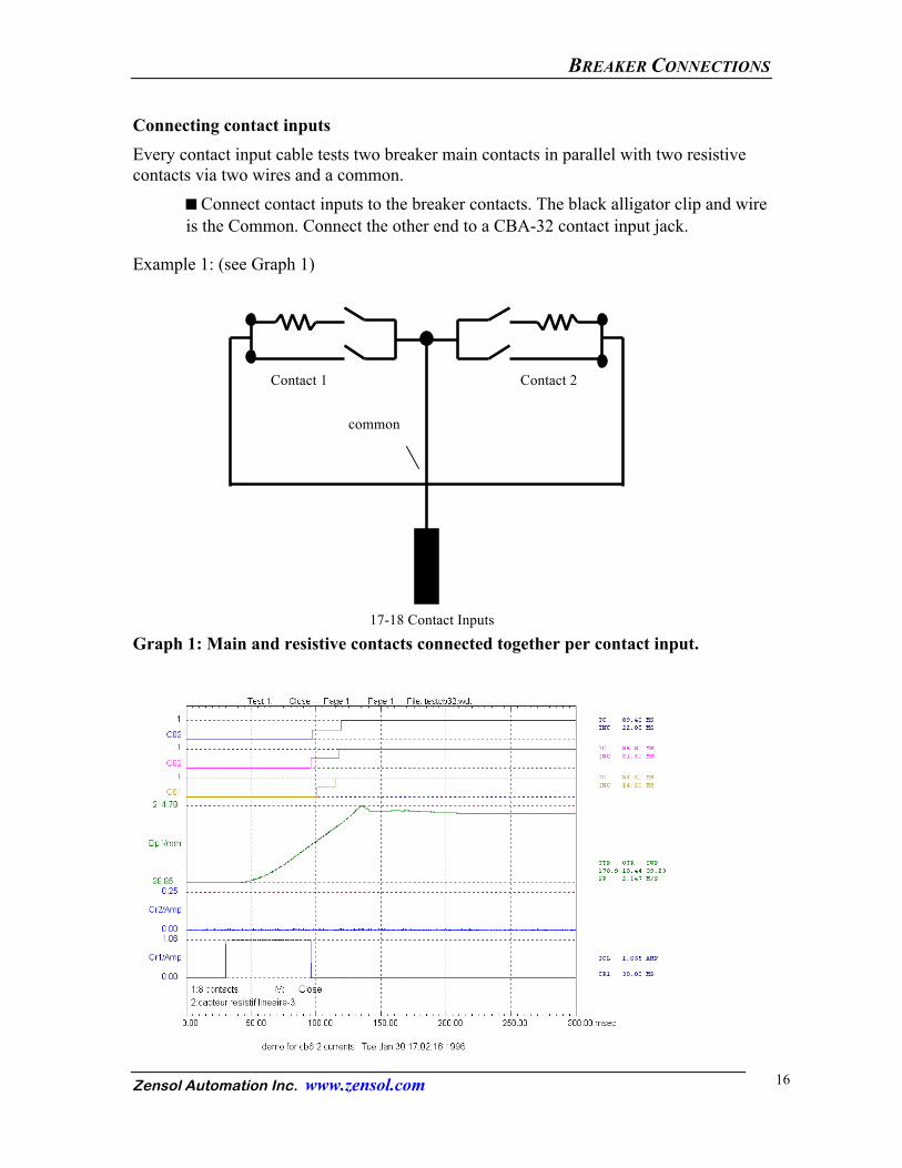
Connecting contact inputs Every contact input cable tests two breaker main contacts in parallel with two resistive contacts via two wires and a common.
■ Connect contact inputs to the breaker contacts. The black alligator clip and wire is the Common. Connect the other end to a CBA-32 contact input jack.
Example 1: (see Graph 1)
Graph 1: Main and resistive contacts connected together per contact input.
common
Contact 1 Contact 2
17-18 Contact Inputs
BREAKER CONNECTIONS
Zensol Automation Inc. www.zensol.com 17
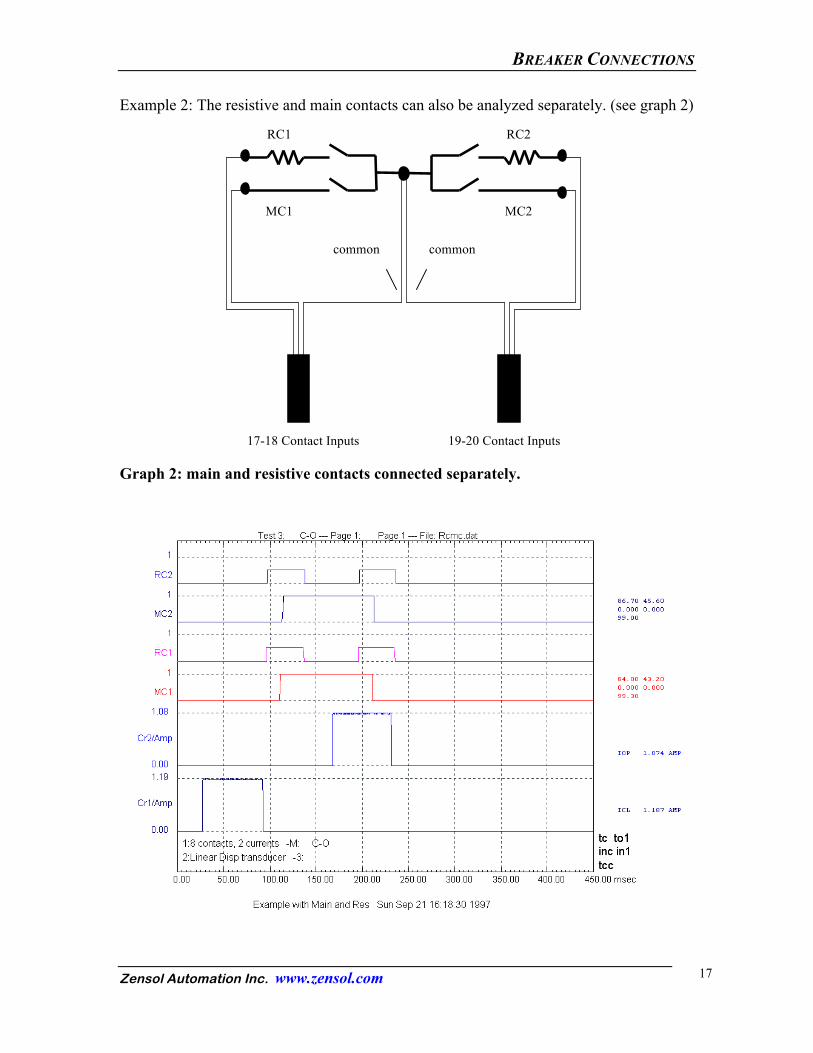
Example 2: The resistive and main contacts can also be analyzed separately. (see graph 2)
Graph 2: main and resistive contacts connected separately.
common common
RC1 RC2
MC1 MC2
17-18 Contact Inputs 19-20 Contact Inputs
BREAKER CONNECTIONS
Zensol Automation Inc. www.zensol.com 18
Connecting linear displacement transducers
■ Attach the linear displacement transducer to the breaker control rod.
■ Connect the linear displacement transducer cable to a 0-10VDC analog input jack on the CBA-32.
Connecting other 0-10VDC transducers
■ Connect any transducer with a 0-10VDC analog output.
You can use any type of transducers such as voltage, pressure, current, moisture, temperature, displacement, velocity, acceleration, etc. Please make sure to have a O-10VDC
BREAKER CONNECTIONS
Zensol Automation Inc. www.zensol.com 19
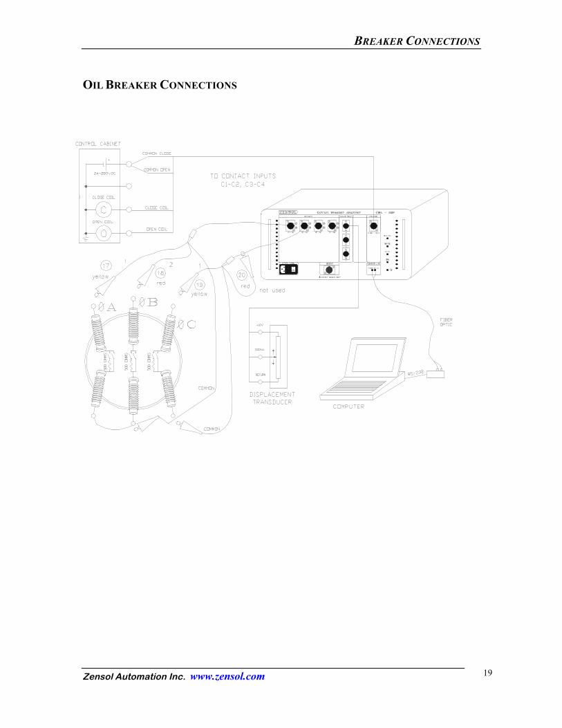
OIL BREAKER CONNECTIONS
BREAKER CONNECTIONS
Zensol Automation Inc. www.zensol.com 20
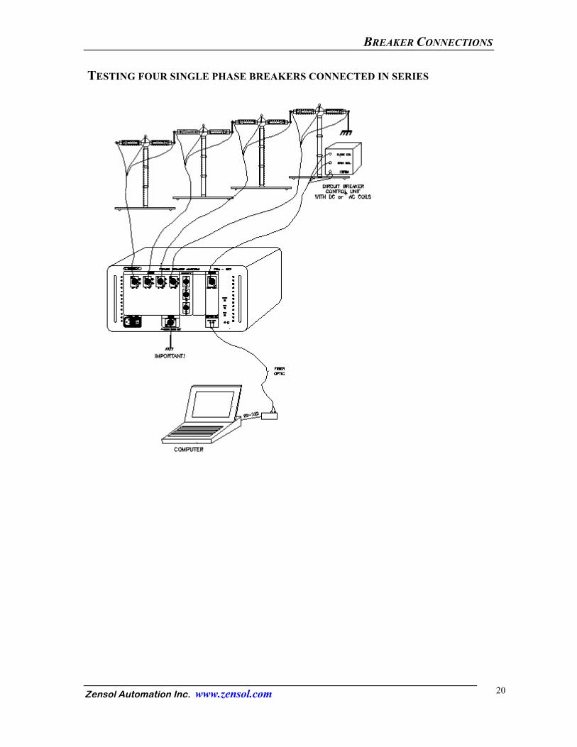
TESTING FOUR SINGLE PHASE BREAKERS CONNECTED IN SERIES
BREAKER CONNECTIONS
Zensol Automation Inc. www.zensol.com 21
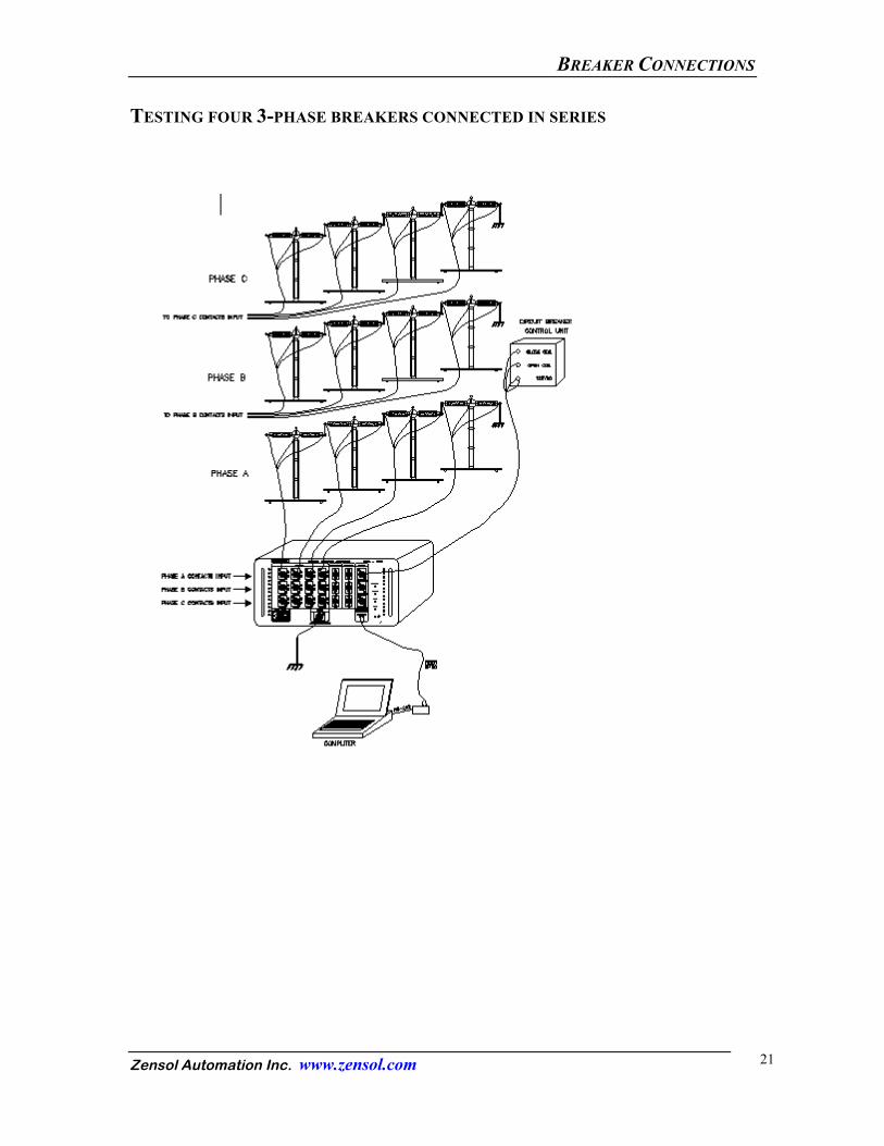
TESTING FOUR 3-PHASE BREAKERS CONNECTED IN SERIES

Zensol Automation Inc. www.zensol.com 22
BREAKER CONNECTIONS

ANSWERS TO VARIOUS QUESTIONS
Zensol Automation Inc. www.zensol.com 23
ANSWERS TO VARIOUS QUESTIONS 1 - Are CBA current sensors shunts? 2 - What is an analog signal in the CBA Win© and the CBA-32P?
3 - Are the contacts suitable for recording? 4 - Can the contacts be viewed?
5 - Can the contacts be named? 6 - Can the analog inputs be named?
7 - Can you choose your own parameters for the analog inputs? 8 - Can the adjustments on the displacement contacts (such as the ones required on the
CSD CBT-4) be avoided? 9 - Can transducers of different lengths be used?
10- What is the purpose of the Relative and the Autoamplification controls in the analog properties dialog?
11- Can the Close and Open (TTL) commands be viewed on the Close and Open relays? 12- How can an analog signal such as displacement be recorded?
13- Can other signals be recorded? 14- Why can only a limited part of the recorded signals be viewed during an Open or
Close command?
15- How to increase the precision of the recordings and see contact bouncing? 16- How to increase the precision on a particular signal?
17- Is it possible to use the recorded values to calculate other parameters? 18- Can a user prepare his own calculation files?
19- Can a user prepare his own tabular reports? 20- Can the fiber optic connection be checked?
21- Can we check the validity of the contacts? 22- How can the analog inputs be checked?
23- How to calibrate the current?
ANSWERS TO VARIOUS QUESTIONS
Zensol Automation Inc. www.zensol.com 24
1- Are CBA current sensors shunts? No. Instead of shunts are powerful current sensors with Hall effect which have been calibrated to 20 amperes. The current is measured by magnetic induction when it goes through these sensors (just like amperemetric cables without contact).
2- What is an analog signal in CBA Win© and the CBA-32P ?
The analog signals in the CBA are identified by their physical and symbolic symbols: Close current is measured by channel number 1 Open current is measured by channel number 2 Displacement inputs are measured by channel numbers 3 to 8.. Note: as the current sensors are built in the CBA-32P, current input numbers 1 and 2 can not be reached by the user.
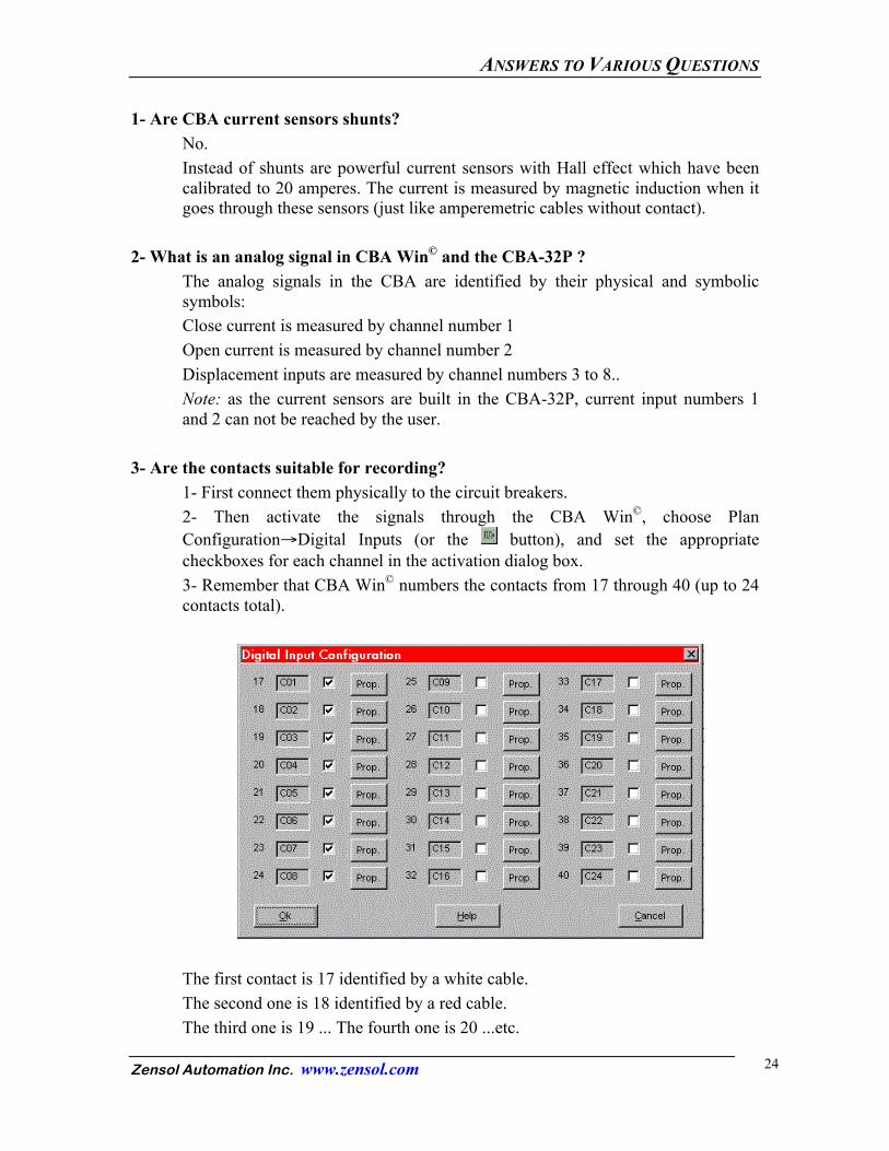
3- Are the contacts suitable for recording?
1- First connect them physically to the circuit breakers. 2- Then activate the signals through the CBA Win©, choose Plan Configuration→Digital Inputs (or the button), and set the appropriate checkboxes for each channel in the activation dialog box. 3- Remember that CBA Win© numbers the contacts from 17 through 40 (up to 24 contacts total).
The first contact is 17 identified by a white cable. The second one is 18 identified by a red cable. The third one is 19 ... The fourth one is 20 ...etc.
ANSWERS TO VARIOUS QUESTIONS
Zensol Automation Inc. www.zensol.com 25
4- Can the contacts be viewed?
Yes. 1- First connect them physically to the circuit breakers. 2- Then activate the signals through CBA Win© 3- Choose Plan Configuration→Processing (or the button) and enter the numbers of the contact inputs to be viewed (17, 18, 19, etc.) 4- Click OK to apply the changes, and click OK in the Processing dialog box. The changes are instantly applied.
5- Can the contacts be named?
Yes. Choose Plan Configuration→Digital Inputs in the menu (or the button), then click on the Prop button of the desired contact signal.. Now name the contacts such as for example PhA, PhB, PhC, 52a, 52b, etc.
6- Can the analog inputs be named?
Yes. Choose Plan Configuration→Analog Inputs in the menu (or the button), and click on the Properties button of the desired analog signal. Now name the contacts such as for example Cr1, Ope or Dp1, Dp2 or Pr, etc.
7- Can you choose your own parameters for the analog inputs?
Yes. Choose Plan Configuration→Analog Inputs in the menu (or the button), and click on the Properties button of the desired analog signal. Then enter Amp for the current unit, mm (millimeter) for the displacement unit, etc. in the Units entry box of the Analog Properties dialog box.
8- Can the adjustments on the displacement contacts (such as the ones required on the CBT-4) be avoided?
Yes (See answer to question 9).
ANSWERS TO VARIOUS QUESTIONS
Zensol Automation Inc. www.zensol.com 26
9- Can transducers of different lengths be used? 1- Choose Plan Configuration→Analog Inputs in the menu (or the button), and click on the Properties button of the desired analog signal. 2- then enter 0 as a minimum and 225 as a maximum (or 600 if the transducer is a 600 mm one). Example: The Novotechnik transducers used by Zensol are 10 volt linear potentiometers (the current required is supplied by the CBA-32P) through our 10V calibrated power supply. The voltage created by the transducer displacement is read by the displacement input (3 to 8) and automatically translated in an absolute or relative value of the precise displacement. (see answer to question 10)
10- What is the purpose of the Relative and Autoamplification controls in the Analog Properties dialog?
Thanks to the Analog Properties, you may choose: - the full scale (autoamplification) option; - 0 is the minimal position in Relative mode (checkbox on). In absolute mode (checkbox off) the signal is visualized as on a voltmeter or an amperemeter; - The numbers between 2 and 9 (Prop. Space) indicate the proportion each signal will take compared to the others. - The numbers between 0 and 5 (Filtering) indicate the amount of graphic filtering (the data are not affected) to remove noise. A filtering setting of 0 means the signal will be displayed as is, while a filter setting of 5 means that the signal will be strongly filtered. Example: 1- Load the demoil.wdt file to observe the effects of the parameters, especially with current and displacement signals. It is preferable: - to enter the current in absolute value and choose the autoamplification option in order to take advantage of the amplifier capabilities of the software, especially in cases of low currents. - Use Relative and Autoamplification for displacement signals. In effect, one is interested solely in the relative position of the transducer with respect to its starting position, and not its absolute position. - Entering a higher number for the Proportional Space of a displacement signal is more useful because a higher area is used to display the signal with better quality.
ANSWERS TO VARIOUS QUESTIONS
Zensol Automation Inc. www.zensol.com 27
11- Can the Close and Open (TTL) commands be viewed on the Close and Open relays ?
For the moment, CBA Win cannot display the Close and Open commands. 12- How can an analog signal such as displacement be recorded?
1- Connect physically the resistive transducer to 3 pins just like a potentiometer. The current required for the transducer is automatically supplied by the CBA-32P. 2- Fix the ground of the potentiometer and the mid-point. 3- be careful of the indications related to the connection entries. 4- Then activate the number related to analog signal which is in this particular case between 3.and 8.
13- Can other signals be registered?
Yes. Every transducer which requires 0-10 volts DC is suitable for recording. Example: The pressure transducers which are 10 volt VDC can be directly connected to the CBA-32P.
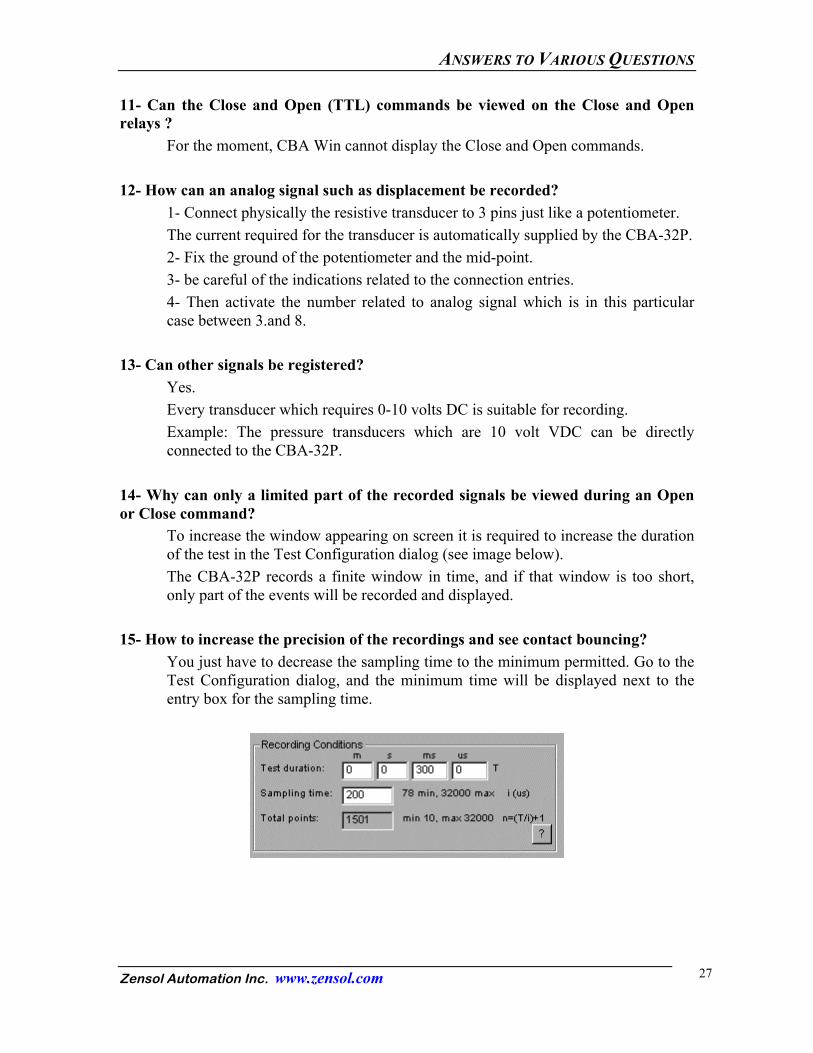
14- Why can only a limited part of the recorded signals be viewed during an Open or Close command?
To increase the window appearing on screen it is required to increase the duration of the test in the Test Configuration dialog (see image below). The CBA-32P records a finite window in time, and if that window is too short, only part of the events will be recorded and displayed.
15- How to increase the precision of the recordings and see contact bouncing?
You just have to decrease the sampling time to the minimum permitted. Go to the Test Configuration dialog, and the minimum time will be displayed next to the entry box for the sampling time.

ANSWERS TO VARIOUS QUESTIONS
Zensol Automation Inc. www.zensol.com 28
16- How to increase the precision on a particular signal? Deactivate all the unnecessary signals then decrease the sampling time. (CBA Win© automatically calculates the minimum sampling time allowed) Please take note of the following: - Signal number 1 is permanently activated; - If one deactivates signal number 3 while signal number 4 is still activated, the minimum sampling time will not be affected since the signals are recorded in their numerical order.
17- Is it possible to use the recorded values to calculate other parameters?
Yes. You just have to pre-prepare the calculus files and to select them via the Processing dialog.by entering the calculus file number in the box title Calculus.
18- Can a user prepare his own calculation files?
Yes. A manual has been especially designed. A training session is also available at Zensol if required. To more information or to arrange this training, please contact us.
19- Can a user prepare his own tabular reports?
Yes. A manual has been especially designed. A training session is also available at Zensol if required. To arrange this training, please call Zensol at the following number (514) 334-5900.
20- Can the fiber optic connection be checked?
1- Connect the RS-232 adapter (fiber optic connection -little black box-) to the PC. 2- Pay attention of the red and black connectors (marked T and R) which have to go through the right RS-232 adapter connections (marked Tx and Rx). 3- Then disconnect the fiber optic cable from the CBA-32P. 4- Do Tests→Test Link in the menu (or the button). 5- A light must appear in one of the fiber optic wires.
ANSWERS TO VARIOUS QUESTIONS
Zensol Automation Inc. www.zensol.com 29
21- Can we check the validity of the contacts? Two simple manipulations can be used: 1- without any connection to the CBA-32P a permanent 0 for Open states must appear on every graph visualized. 2- By provoking a short circuit between the terminals (white or red) and the common terminal, a permanent 1 for Close state must appear on every graph viewed. 3- By connecting a 500 Ohm or a 100 Ohm resistor between the common terminal and the terminals (white or red), a 0.5 state will appear on the related graph. 4- Using the same arrangement as in step 2, do Tests→Test Cables in the menu (or the button) and click OK at the warning message. A window will appear showing which contacts are valid/short-circuited (check boxes on with a white background) or open (check boxes off with white background). Note that only the activated contact signals will be tested.
22- How can the analog inputs be checked?
1- Choose the signal which is going to be checked, from 3 to 8, and connect a cable. 2- Activate the required signal in the Analog activation screen and in the Properties dialog of that signal, set the Min (0V) to 0 and the Max (10V) to 10. 3- Apply a 0 volt voltage by making a short circuit between the Signal and Common wires of the analog signal tested. 4- Execute a test with CBA Win. 5- View the graph (displayed instantly after the test). 6- Check that 0 volts appears on the graph of the tested signal using the Examine tool. 7- Apply a 10 volt signal by disconnecting the Signal wire from the Common and connecting the Signal to the 10 volt wire. 8- Repeat steps 4 through 6 and check for 10 volts on the signal tested.
23- How to calibrate the currents? Choose Plan Configuration→Analog Inputs from the menu (or the x button) and click on the Properties button of either signal 1 or signal 2 (the current sensors). Enter the following allowable combinations of values into the Min (0V) and Max (10V) entry boxes: Min (0V) 0 -5 0 -10 0 -20 Max (10V) 5 5 10 10 20 20