Embed Size (px)
Citation preview
1
Conceptual design of a multi-mirror system for asteroid deflection
By Massimiliano VASILE1), Christie Alisa MADDOCK1) and Leopold SUMMERER2)
1)Space Advanced Research Team, Dept. of Aerospace Engineering, University of Glasgow, United Kingdom
2)Advanced Concepts Team, European Space Agency ESA/ESTEC, The Netherlands
This paper presents the conceptual design of multiple spacecraft system for the use of deflecting Near Earth Asteroids. Each spacecraft is equipped with a solar concentrator assembly, which focuses the solar light, and a beaming system that projects a beam of light onto the surface of the asteroid. When the beams from each spacecraft are superimposed, the temperature on the surface is enough to sublimate the rock, creating a debris plume with enough force to slowly alter the orbit of Apophis. An overview of the dynamics, control and navigation strategies are presented along with simulated results of the deviation distance achieved for various mission configurations.
Key Words: Asteroid deflection, solar sublimation, formation flying
Nomenclature
a : semi-major axis, km A : area, m2 c : speed of light, 299792.458 km/s Cineq : inequality constraint function Cr : concentration ratio d : diameter e : eccentricity f : true anomaly F, F : force, N H : enthalpy of sublimation, J h : height, m i : inclination, rad J : objective function jC : jet constant k : set of Keplerian orbital elements k : Boltzmann constant, 1.3807E-23 J/K M : mean anomaly, rad M : molecular mass, kg m : mass, kg n : normal vector P : power, W Q : heat loss, J r, r : position, km rAU : distance at 1 AU, 149597870.7 km S0 : solar flux at 1 AU, 1367 W/m2 T : orbital period, days or temperature, K t : time, s u : perturbing acceleration vector, km/s2 v, v : velocity, km/s ! : albedo " : degradation factor, % # : efficiency, % $ : true latitude (f + %), rad
& : adiabatic index ! : scattering factor ' : gravitational constant, km3/s2 ( : density, kg/m3 ) : absorption coefficient " : elevation angle, rad ! : angle of reflection, rad % : argument of periapsis, rad # : right ascension of ascending node, rad
Subscripts 0 : initial A : asteroid or NEO cnd : condensation cond : conduction dev : deviation exp : expelled (debris) lim : limit M : mirror pert : perturbations rad : radiation sc : spacecraft spot : spot on the asteroid surface srp : solar radiation pressure subl : sublimation sun : Sun sys : system thrust : thrust produced by deviation action warn : warning before a epoch
1. Introduction
In 2004, astronomers first sighted the asteroid Apophis. Based on tracking data, it is known that in 2029 the asteroid will have a close approach with the Earth. Depending on the interaction with the Earth’s gravity field, Apophis might be put into a resonant return orbit with the first potential impact

2
in 2036. Apophis is only one of 6190 Near Earth Objects (NEO) detected, with 1053 listed as potentially hazardous by the IAU Minor Planet Center*. Due the danger posed by an impact, many scientists in the last few decades have proposed several deflection methods. Based on a quantitative comparison of the various options for NEO deflection 1), one of the more interesting and promising methods, initially proposed by Melosh and Nemchinov 2) in 1993, and later assessed by Kahle et al. 3), employs solar sublimation to actively deviate the orbit of the asteroid. The original concept envisioned a single large reflector; this idea was expanded by the authors to a formation of spacecraft orbiting in the vicinity of the NEO, each equipped with a smaller concentrator assembly coupled with solar pumped laser capable of focusing a beam of light at a distance around 1 km and greater. This relieved the strict constraint on the proximity to the asteroid surface, mitigating the effects of the inhomogeneous gravity field, the contamination due to the debris plume, as well as temperature concerns by the high magnification ratio.
The following paper presents results of a hypothetical deflection mission of the NEO Apophis including the orbital dynamics, control and navigation strategies, accounting for solar radiation pressure, the gravity field of the asteroid, and the deviation of the NEO orbit. Trade-offs are presented based on the warning time, thrust period, and total deviation distance achieved versus a number of system design parameters.
2. Focusing and beaming system
In order to sublimate the rock, the asteroid surface must be heated to a minimum temperature of 1800 K; the sublimation temperature of forsterites 1). A number of different system configurations were examined that concentrates the solar flux (S0 = 1367 W/m2) to the power density required on the surface. The system used in the following analysis consists of a primary paraboloidic reflector which focuses the solar radiation onto an indirect-pumped laser system, which is then re-directed onto a specific spot on the NEO by a small directional mirror. The concentration ratio, Cr, is defined as the ratio between the total surface area of the primary mirror normal to the Sun vector, and the surface area of the spot on the NEO. The laser system is composed of a semi-conductor laser, which while at a lower technology readiness level (TRL) than solid-state lasers offers potentially much higher power conversion efficiencies, which is powered by a set of solar arrays. Using a laser plug efficiency 4) of 73% and a solar cell efficiency 5) of 50%, the total efficiency would be 36.5%. To be conservative, a value of !sys = 25% was used for the simulations 6). The laser system, directional mirror and radiators are placed in the shadow of the primary mirror to help reduce excess heat.
3. Proximal motion dynamics and control
The formation orbits are based on the proximal motion equations 7) for a chief-deputy arrangement.
* IAU Minor Planet Center, http://www.cfa.harvard.edu/iau/mpc.html
( )22 3
23
3
( ) 2
( ) 2
( )
A sun sunA A A
A A sc
A sunA A
A sc
sun
sc
rx t f y xf r x
r r r
ry t f x yf y
r r
z t zr
µ µ
µ
µ
! "= ! + + ! +# $
% &
! "= ! ! + !# $
% &
= !
!! !!!
!! !!!
!!
(1)
Adapted to this case, the chief orbit is that of the NEO, and the deputy orbit is the one of the spacecraft. The NEO-spacecraft vector is given by [ ], ,x y z" =r in radial-transverse-normal directions.
Fig. 1 Dual reflector system with an indirect-pumped rear laser system. The arrows show the direction of solar radiation pressure on each surface.
Nonlinear equations for the relative position in the local Hill reference frame were developed as a function the difference between the angular Keplerian elements of the NEO and those of the spacecraft 8).
( ) ( )
cos sin( ) cos sin
cos sin sin sinf
i
# $ % $" % $ # $
$ "$ " & $ "$
+' () *= ! +) *) *! ! ' + !+ ,
r (2)
( )
cos cos( ) cos( )sin sin( )cos sin( ) cos cos( )sincos cos( )sin
cos cos( )cos sin( )sin sin( )
i ii i i i i ii
i i i i i i
# " "$ $ " " "$ $& " " "% "$ $ "
" " " "$ $
= ! ' ! + ! ' != ! + ' != ! '+ ' ! ! ! !
At small distances (i.e., Ar r" " ), these are equivalent to the linearised set of relative motion equations developed by Schaub 7).
The same nonlinear proximal motion equations were used to calculated the total deflection distance of the asteroid !rdev, using the change in Keplerian between the original and deviated orbits at a given time, in this case the time at which a minimum orbit interception distance (MOID) occurs 9).
The set of orbital element differences,
[ ]0sc A a e i M" " " " " "( "= ! = = 'k k k (3)
was optimized based on two different sets of objective functions. The difference in semi-major axis is set to zero to ensure the periodicity of the two orbits (i.e. spacecraft and NEO).
x
y
M1
M3
M2
L
3
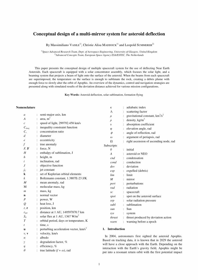
Fig. 2. Set of 20 Pareto-optimal orbits for objective functions J1, J2.
The first optimization aimed to maintain a constant distance !r from the NEO subject to a constraint to ensure that the spacecraft remain outside a limiting sphere based on the gravitational field of the NEO 8).
2 21 2, ,
min , min subject to ineq limf fJ r J x z C r r
! !! != = + = >
k k (4)
The optimal direction of thrust, given a suitable warning time, is along the direction of velocity, or in this case along the y-axis. Given the possible wide scattering of the debris, the second set aims instead to maximize the allowable region for the debris plume through the centre of the orbit.
3 2 2,min arctan subject to minineq limf
yJ C y r
x z!
! "= = ># $
+% &k(5)
Fig. 3. Set of 25 optimized orbits for objective function J3.
Two major disturbances to the orbits are the solar radiation pressure (SRP) acting on the mirror surfaces, and the gravitation effect of the asteroid. The orbits were intentionally situated at a distance far enough away such that the gravity field can be considered as a point source. In order to maintain the orbit, a feedback control law in employed which minimizes the difference between the actual and desired orbit element differences vector, !k. The control law also compensates for the continual deviation of the NEO 10).
The orbits of the spacecraft and asteroid were propagated by integrating Gauss’ form of the variational equations 11). The acceleration produced by the deflection method is a direct
0 10 20
-0.2
-0.1
0
" a
(m)
0 10 20
-10-505
x 10-3
" e
(10--
9 )
0 10 20
-10
-5
0x 10
-4
" i (
10--
9 rad)
0 10 20
-4
-2
0
x 10-3
"# (1
0--9 ra
d)
0 10 20-0.02
-0.01
0
"$ (1
0--9 ra
d)
Mission duration (days)
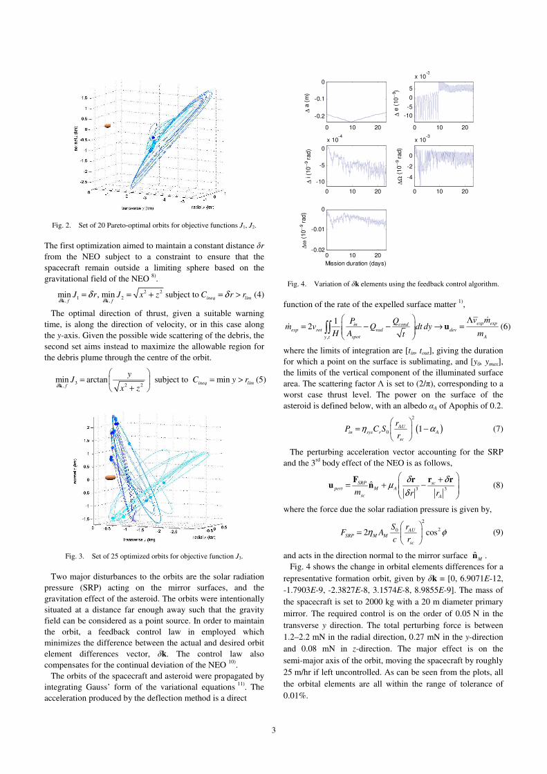
Fig. 4. Variation of !k elements using the feedback control algorithm.
function of the rate of the expelled surface matter 1),
,
12 exp expin condexp rot rad dev
spot Ay t
v mP Qm v Q dt dy
H A mt
! " %= & & ' =# $# $
% &'' u
!
! (6)
where the limits of integration are [tin, tout], giving the duration for which a point on the surface is sublimating, and [y0, ymax], the limits of the vertical component of the illuminated surface area. The scattering factor ! is set to (2/"), corresponding to a worst case thrust level. The power on the surface of the asteroid is defined below, with an albedo "A of Apophis of 0.2.
( )2
0 1AUin sys r A
sc
rP C S
r( )! "
= &# $% &
(7)
The perturbing acceleration vector accounting for the SRP and the 3rd body effect of the NEO is as follows,
3 3ˆSRP scpert M A
sc Am r r
! !µ!
! "+# $= + &# $% &
F r r ru n (8)
where the force due the solar radiation pressure is given by,
2
202 cosAUSRP M M
sc
S rF A
c r( *! "
= # $% &
(9)
and acts in the direction normal to the mirror surface ˆ Mn . Fig. 4 shows the change in orbital elements differences for a
representative formation orbit, given by !k = [0, 6.9071E-12, -1.7903E-9, -2.3827E-8, 3.1574E-8, 8.9855E-9]. The mass of the spacecraft is set to 2000 kg with a 20 m diameter primary mirror. The required control is on the order of 0.05 N in the transverse y direction. The total perturbing force is between 1.2–2.2 mN in the radial direction, 0.27 mN in the y-direction and 0.08 mN in z-direction. The major effect is on the semi-major axis of the orbit, moving the spacecraft by roughly 25 m/hr if left uncontrolled. As can be seen from the plots, all the orbital elements are all within the range of tolerance of 0.01%.
4
4. Navigation
A key requirement for the successful implementation of the multi-mirror approach is that each spacecraft must know their position relative to both the NEO and the other spacecraft in the formation, and be able to find and maintain the direction of the beam onto a precise spot on the surface of the asteroid.
The navigation strategy is based on the attitude measurements, given by an onboard star tracker, the inertial position of each spacecraft, and the 2D image from a rotating onboard camera. Once the formation is deployed in the vicinity of the NEO, one spacecraft is temporarily designated as leader and searches the predicted location of the NEO until it is within the field of view of the camera. Using simple geometry, the centroid of the image is determined and aligned with the boresight of the camera. The pointing vector from the lead spacecraft is then relayed to the whole formation. Once all the spacecraft have acquired the centre of the NEO, the spacecraft-asteroid range can be triangulated 6).
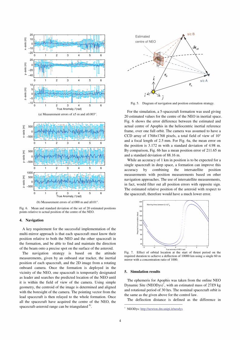
Fig. 5. Diagram of navigation and position estimation strategy.
For the simulation, a 5-spacecraft formation was used giving 20 estimated values for the centre of the NEO in inertial space. Fig. 6 shows the error difference between the estimated and actual centre of Apophis in the heliocentric inertial reference frame, over one full orbit. The camera was assumed to have a CCD array of 1768!1768 pixels, a total field of view of 10° and a focal length of 2.5 mm. For Fig. 6a, the mean error on the position is 3.172 m with a standard deviation of 4.98 m. By comparison, Fig. 6b has a mean position error of 211.65 m and a standard deviation of 88.16 m.
While an accuracy of 1 km in position is to be expected for a single spacecraft in deep space, a formation can improve this accuracy by combining the intersatellite position measurements with position measurements based on other navigation approaches. The use of intersatellite measurements, in fact, would filter out all position errors with opposite sign. The estimated relative position of the asteroid with respect to the spacecraft, therefore would have a much lower error.
!3 !2 !1 0 1 2 3
40
60
80
100
120
140
160
180
200
220
Warning times between [4, 6] TA
True anomaly of NEO (rad)
Req
uire
d th
rust
dur
atio
n (d
ays)
Fig. 7. Effect of orbital location at the start of thrust period on the required duration to achieve a deflection of 10000 km using a single 60 m mirror with a concentration ratio of 1000.
5. Simulation results
The ephemeris for Apophis was taken from the online NEO Dynamic Site (NEODys)†, with an estimated mass of 27E9 kg and rotational period of 30 hrs. The nominal spacecraft orbit is the same as the given above for the control law.
The deflection distance is defined as the difference in † NEODys: http://newton.dm.unipi.it/neodys
0 1 2 3 4 5 6!20
!10
0
10
20
x!ax
is (m
)
0 1 2 3 4 5 6
!40
!20
0
20
y!ax
is (m
)
0 1 2 3 4 5 6!10
!5
0
5
10
True Anomaly, f (rad)
z!ax
is (m
)
(a) Measurement errors of ±5 m and ±0.003°.
0 1 2 3 4 5 6
!500
0
500
x!ax
is (m
)
0 1 2 3 4 5 6
!500
0
500
y!ax
is (m
)
0 1 2 3 4 5 6
!500
0
500
1000
True Anomaly, f (rad)
z!ax
is (m
)
(b) Measurement errors of ±1000 m and ±0.01°.
Fig. 6. Mean and standard deviation of the set of 20 estimated positions points relative to actual position of the centre of the NEO.
s/c B
s/c A
Estimated centre of NEO
k
i j
AB!r
Br
Ar

5
position vector from the Earth to Apophis at the true anomaly of the MOID. For the following, the simulations use the MOID at tMOID =13252.06736 MJD2000 (13 April 2036). The start of the thrust leg is given by ( )MOID WARNt t! for a duration of !tthrust. Due to the eccentricity of the orbit of Apophis (eA = 0.1912), the effect of the thrust on the deflection distance changes depending on the orbital location. For an equal
comparison therefore, the warning and thrust times are given as multiples of the orbital period of the NEO (TA = 323.56 days) so the starting true anomaly is always the same, in this case 2.6908MOIDf = ! rad. Fig. 7 shows the difference in required thrust time for a set of warning times of 1294-1941 days.
Fig. 8 to Fig. 10 show the achieved deflection distance at the MOID with the Earth in 2036 varying the number of satellites, concentration ratios and warning time/thrust duration. The limit on the effectiveness of increasing the concentration ratio can also be seen from both graphs.
Fig. 11 shows the total mass of the expelled debris from the NEO versus a fixed system concentration ratio of 3000, i.e. the number of spacecraft times the concentration ratio of each individual spacecraft. The thrust magnitude depends on the input power and surface area illuminated by the beam. As the concentration ratio increases, the area, for a fixed size mirror, decreases and therefore the thrust does not improve. On the other hand, superimposing the beams increases the power density and leaves the size of the spot area unchanged. Therefore, rather than increasing the concentration ratio, the ideal strategy would be to increase the number of beams with constant concentration ratio. 5.1. Mirror contamination and degradation
The contamination of the mirror surfaces due to the debris plume was modelled based on the work by Kahle et al. 3) The study is based on a number of initial assumptions regarding the expansion of the plume and sublimation process. The first assumption holds that the sublimation process is comparable to the generation of tails in comets. The asteroid is assumed to contain a reservoir of material underneath the surface, with the gas expanding both outwards as expected, and inwards through a throat into vacuum within the asteroid itself. This assumption holds true, for example, for a loose rubble-pile asteroid model. The second assumption is that the plume expansion is similar to the expansion of gas of a rocket engine outside the nozzle.
The density of the gas is computed analytically,
( )
( ) 21
2
2( , ) cos2
exp spotexp C
spot exp spot
m dr j
A v r d"# $ != %
+
!
(10)
where r is the distance from the spot on the surface of the asteroid, and 2 max&$ $% = where ! is the elevation angle of
Concentration ratio
Num
ber o
f spa
cecr
aft
Deflection distance (km)
10001000
10001000
20002000
20002000
3000
3000
3000
4000
40004000
5000
5000
5000
6000
6000
7000
7000
8000
8000
9000
500 1000 1500 2000 2500 30001
2
3
4
5
6
7
8
9
10
1000
2000
3000
4000
5000
6000
7000
8000
9000
10000
Fig. 8. Deflection distance (km) including mirror degradation for a 20 m diameter primary mirror, a warning time and thrust period of 2TA.
10000
10000
1000010000
20000
20000
20000
30000
30000
30000
40000
40000
40000
50000
50000
60000
60000
70000
70000
80000
80000
90000
90000
100000110000
120000130000
Warning time, twarn
= thrust time, tthrust
(multiples of TA)
Num
ber o
f spa
cecr
aft
Deflection distance (km)
1 2 3 4 5 6 7 81
3
5
7
9
11
13
15
2
4
6
8
10
12
14x 10
4
Fig. 9. Deflection distance including mirror degradation for a 20 m diameter primary mirror, with concentration factor Cr of 2000.
1000
1000
1000
2000
2000
2000
3000
3000
3000
4000
4000
5000
5000
6000
6000
7000
70008000
90001000011000
12000
Warning time, twarn
= thrust time, tthrust
(multiples of TA)
Num
ber o
f spa
cecr
aft
Deflection distance (km)
1 2 3 4 5 6 7 81
3
5
7
9
11
13
15
2000
4000
6000
8000
10000
12000
14000
Fig. 10. Deflection distance including mirror degradation for a 5 m diameter primary mirror, with concentration factor Cr of 2000.
1x3000 2x1500 3x1000 4x750 5x6000
1
2
3
4
5
6x 10
6
(n spacecraft) x (concentration ratio)
Tota
l mas
s of
exp
elle
d de
bris
(kg)
Fig. 11. Mass of asteroid debris expelled by sublimation versus a fixed system concentration ratio, assuming each spacecraft has 40 m diameter mirror, thrusting for a duration of 2TA, equal to the warning time.
6
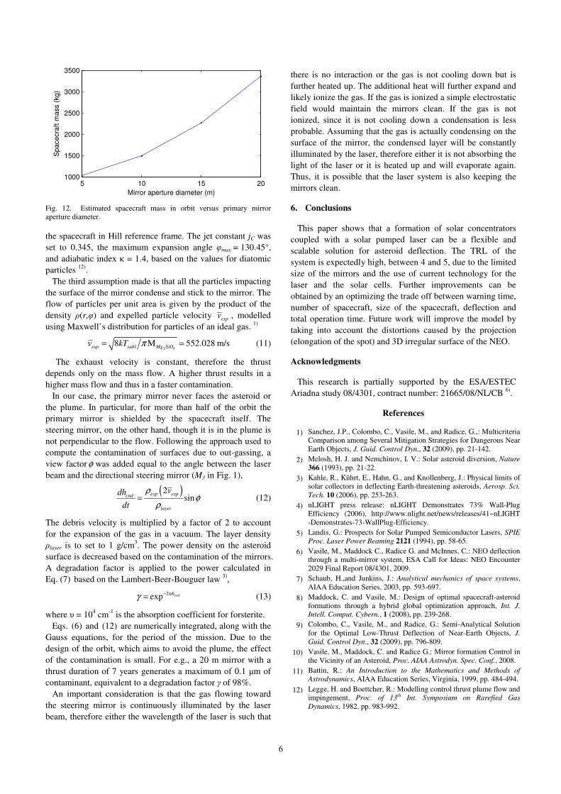
the spacecraft in Hill reference frame. The jet constant jC was set to 0.345, the maximum expansion angle !max = 130.45°, and adiabatic index ! = 1.4, based on the values for diatomic particles 12).
The third assumption made is that all the particles impacting the surface of the mirror condense and stick to the mirror. The flow of particles per unit area is given by the product of the density "(r,!) and expelled particle velocity expv , modelled using Maxwell’s distribution for particles of an ideal gas. 1)
2 4
8 552.028 m/sexp subl Mg SiOv kT != " ! (11)
The exhaust velocity is constant, therefore the thrust depends only on the mass flow. A higher thrust results in a higher mass flow and thus in a faster contamination.
In our case, the primary mirror never faces the asteroid or the plume. In particular, for more than half of the orbit the primary mirror is shielded by the spacecraft itself. The steering mirror, on the other hand, though it is in the plume is not perpendicular to the flow. Following the approach used to compute the contamination of surfaces due to out-gassing, a view factor# was added equal to the angle between the laser beam and the directional steering mirror (M3 in Fig. 1),
( )2
sinexp expcnd
layer
vdhdt
$#
$= (12)
The debris velocity is multiplied by a factor of 2 to account for the expansion of the gas in a vacuum. The layer density "layer is to set to 1 g/cm3. The power density on the asteroid surface is decreased based on the contamination of the mirrors. A degradation factor is applied to the power calculated in Eq. (7) based on the Lambert-Beer-Bouguer law 3),
2exp cndh%& '= (13)
where " = 104 cm-1 is the absorption coefficient for forsterite. Eqs. (6) and (12) are numerically integrated, along with the
Gauss equations, for the period of the mission. Due to the design of the orbit, which aims to avoid the plume, the effect of the contamination is small. For e.g., a 20 m mirror with a thrust duration of 7 years generates a maximum of 0.1 #m of contaminant, equivalent to a degradation factor # of 98%.
An important consideration is that the gas flowing toward the steering mirror is continuously illuminated by the laser beam, therefore either the wavelength of the laser is such that
there is no interaction or the gas is not cooling down but is further heated up. The additional heat will further expand and likely ionize the gas. If the gas is ionized a simple electrostatic field would maintain the mirrors clean. If the gas is not ionized, since it is not cooling down a condensation is less probable. Assuming that the gas is actually condensing on the surface of the mirror, the condensed layer will be constantly illuminated by the laser, therefore either it is not absorbing the light of the laser or it is heated up and will evaporate again. Thus, it is possible that the laser system is also keeping the mirrors clean.
6. Conclusions
This paper shows that a formation of solar concentrators coupled with a solar pumped laser can be a flexible and scalable solution for asteroid deflection. The TRL of the system is expectedly high, between 4 and 5, due to the limited size of the mirrors and the use of current technology for the laser and the solar cells. Further improvements can be obtained by an optimizing the trade off between warning time, number of spacecraft, size of the spacecraft, deflection and total operation time. Future work will improve the model by taking into account the distortions caused by the projection (elongation of the spot) and 3D irregular surface of the NEO.
Acknowledgments
This research is partially supported by the ESA/ESTEC Ariadna study 08/4301, contract number: 21665/08/NL/CB 6).
References
1) Sanchez, J.P., Colombo, C., Vasile, M., and Radice, G.,: Multicriteria Comparison among Several Mitigation Strategies for Dangerous Near Earth Objects, J. Guid. Control Dyn., 32 (2009), pp. 21-142.
2) Melosh, H. J. and Nemchinov, I. V.: Solar asteroid diversion, Nature 366 (1993), pp. 21-22.
3) Kahle, R., Kührt, E., Hahn, G., and Knollenberg, J.: Physical limits of solar collectors in deflecting Earth-threatening asteroids, Aerosp. Sci. Tech. 10 (2006), pp. 253-263.
4) nLIGHT press release: nLIGHT Demonstrates 73% Wall-Plug Efficiency (2006), http://www.nlight.net/news/releases/41~nLIGHT -Demonstrates-73-WallPlug-Efficiency.
5) Landis, G.: Prospects for Solar Pumped Semiconductor Lasers, SPIE Proc. Laser Power Beaming 2121 (1994), pp. 58-65.
6) Vasile, M., Maddock C., Radice G. and McInnes, C.: NEO deflection through a multi-mirror system, ESA Call for Ideas: NEO Encounter 2029 Final Report 08/4301, 2009.
7) Schaub, H.,and Junkins, J.: Analytical mechanics of space systems, AIAA Education Series, 2003, pp. 593-697.
8) Maddock, C. and Vasile, M.: Design of optimal spacecraft-asteroid formations through a hybrid global optimization approach, Int. J. Intell. Comput. Cybern., 1 (2008), pp. 239-268.
9) Colombo, C., Vasile, M., and Radice, G.: Semi-Analytical Solution for the Optimal Low-Thrust Deflection of Near-Earth Objects, J. Guid. Control Dyn., 32 (2009), pp. 796-809.
10) Vasile, M., Maddock, C. and Radice G.: Mirror formation Control in the Vicinity of an Asteroid, Proc. AIAA Astrodyn. Spec. Conf., 2008.
11) Battin, R.: An Introduction to the Mathematics and Methods of Astrodynamics, AIAA Education Series, Virginia, 1999, pp. 484-494.
12) Legge, H. and Boettcher, R.: Modelling control thrust plume flow and impingement, Proc. of 13th Int. Symposium on Rarefied Gas Dynamics, 1982, pp. 983-992.
5 10 15 201000
1500
2000
2500
3000
3500
Mirror aperture diameter (m)
Spa
cecr
aft m
ass
(kg)
Fig. 12. Estimated spacecraft mass in orbit versus primary mirror aperture diameter.


![[DGD] - Hyper Asteroid](https://img.pdfslide.net/doc/110x75/563db95d550346aa9a9ca4a3/dgd-hyper-asteroid.jpg)

