Embed Size (px)
Citation preview
ASSESSMENT OF TWO BWR ACCIDENT MANAGEMENT STRATEGIES*
S. A. Hodge, M. Petek
Oak Ridge National LaboratoryOak Ridge, Tennessee 37831
CONF-9U079--2
DE92 002318
ABSTRACT
Candidate mitigative strategies for management of in-vessel events during the late phase(after core degradation has occurred) of postulated BWR severe accidents wereconsidered at Oak Ridge National Laboratory (ORNL) during 1990. The identificationof new strategies was subject to the constraint that they should, to the maximum extentpossible, make use of the existing equipment and water resources of the BWR facilitiesand not require major equipment modifications or additions. As a result of this effort,two of these candidate strategies were recommended for additional assessment. Thefirst is a strategy for containment flooding to maintain the core and structural debriswithin the reactor vessel in the event that vessel injection cannot be restored to terminatea severe accident sequence. The second strategy pertains to the opposite case, forwhich vessei injection would be restored after control blade melting had begun; itspurpose is to provide an injection source of borated water at the concentration necessaryto preclude criticality upon recovering a damaged BWR core.
Assessments of these two strategies have been performed during 1991 under theauspices of the Detailed Assessment of BWR In-Vessel Strategies Program. This paperprovides a discussion of the motivation for and purpose of these strategies and thepotential for their success.
1. INTRODUCTION
Boiling Water Reactors (BWRs) have unique features that would cause their behavior undersevere accident conditions to differ significantly from that expected for the pressurized waterreactor design1'5. Consequently, it has been necessary to analyze BWR accident sequencesseparately, and the NRC has sponsored programs at ORNL for this purpose since 19806. Theobjective of these BWR severe accident programs has been to perform analyses of a spectrum ofaccident sequences beyond the design basis for typical specific U.S. BWR reactor designs. Theaccident sequences selected for analysis have been in general those identified as dominant inleading to core melt for BWRs by the methods of probabilistic risk assessment (PRA) as carriedout by other programs. The specific plants modeled and the accident sequences considered wereselected by the process of nomination by the ORNL program manager and approval by the NRCtechnical monitors.
'Research sponsored by the Office of NuclearRegulatory Research, U.S. Nuclear RegulatoryCommission under Interagency AgreementNo. 1886-8045-2B with the U.S. Department ofEnergy under contract DE-AC05-64OR21400 withMartin Marietta Energy Systems, Inc.
'The submitted manuscript has been authored bya contractor ol the U.S. Government undercontract No. DE-AC05-84OR21400. Accordingly,the U.S. Government retain* a nonexclusive,royalty-free license to publish or reproduce Ihepublished form ot this contribution, or allowothers to do so, for U.S. Government purposes.*
DISTRIBUTION OF THIS DOCUMENT IS UNLIMITED

The detailed analyses of the dominant severe accident sequences identified by PRA have beenperformed in recognition that PRA, by the basic nature of its requirements to consider everypossible accident sequence, cannot enter into matters of detail. The purpose of the detailedanalyses has been either to confirm the adequacy of or to challenge the simplifying assumptionsnecessarily applied to each accident sequence in the PRA and to provide a realistic appraisal of thesequence of events and the aftermath. Further preventive measures that might be taken to decreasethe probability of each severe accident sequence studied and accident management procedures thatmight be implemented to reduce the consequences have been addressed. Feedback of the results ofthe detailed analyses has always been provided to the other facilities performing the PRA; mostrecently, this has involved close cooperation with the NUREG-1150 effort7 at Saadia NationalLaboratories (SNL).
With the comprehensive information provided by NUREG-1150 concerning the relativeprobabilities of BWR severe accident sequences and with the knowledge and experience gainedfrom the series of detailed accident analyses8"22, the next logical step was to consider the facets ofBWR severe accident management in a structured process, with the goal of identifying potentialnew strategies and enhancements. This was accomplished by means of an assessment of thecurrent status of accident management procedures with respect to effective mitigation of thedominant BWR severe accident sequences. The accident sequences considered were StationBlackout and Anticipated Transient Without Scram (ATWS), which have been consistentlyidentified by PRA to be the predominant contributors to the overall calculated core damagefrequency for BWR internally-initiated accidents. There are two primary categories of StationBlackout, each leading to severe core damage if unmitigated, but at widely separated times. Forthe short-term case, reactor vessel injection capability is lost at the inception of the accident andcore damage begins during the second hour after scram. For the long-term case, vessel injection islost only after battery failure and core damage occur more than ten hours after scram. For ATWSas in Station Blackout, core damage would occur as a result of loss of vessel injection capability;this, however, is not expected to occur unless the ATWS involves reactor vessel isolation [closureof the main steam isolation valves (MSIVs)] and is compounded by failure of the plant boroninjection system (or systems). The timing of core damage for an ATWS accident sequence thatprogressed this far would be determined by the effectiveness of the delaying actions taken by theplant operators.
The BWR Owners' Group Emergency Procedure Guidelines (EPGs)23 were examined fromthe standpoint of their application to Station Blackout and ATWS. This was done for two reasons.The first objective was to determine the extent to which the EPGs currently implement the intent ofthe BWR accident management strategies that have been suggested in the report24 Assessment ofCandidate Accident Management Strategies (NUREG/CR-5474), published in March 1990. Thesecond objective was to determine the extent to which the current operator actions specified by theEPGs would be effective in unmitigated severe accident situations. It was found that many of therecommended strategies are included in the current version (Revision 4) of the EPGs and that withone exception, the remaining involve plant-specific considerations to die extent that they may bemore appropriate for inclusion within local plant emergency procedures than within the genericsymptom-oriented EPGs. The exception is a strategy for injection of boron following core damageand control blade relocation, which clearly would be appropriate for the EPGs.
With respect to the second objective, the EPGs do not include guidelines for the late phase in-vessel events that would occur only after the onset of significant core damage. Instead, theguidance terminates with the specification of alternate methods for injecting water into the reactorvessel. The conclusions of this examination of the EPGs a.c documented in Reference 25; the

primary conclusions are that more can be done to provide guidance for late-phase operator actionsand that the greatest potential for improvement of the existing BWR emergency procedurestrategies lies in the area of severe accident management, both for determining the extent ofongoing damage to the in-vessel structures and for attempting to terminate the accident
Based upon the results of these analyses, a second in-vessel severe accident managementstudy26 was undertaken to propose new strategies for mitigation of the late-phase events and toprovide a discussion of the motivation for these strategies and a general description of the methodsby which they might be carried out. Four candidate late accident mitigation strategies wereproposed. These are:
1. Keep the Reactor Vessel Depressurized. Reactor vessel depressurization is importantshould an accident sequence progress to the point of vessel bottom head penetration failure becauseit would preclude direct containment heating (DCH) and reduce the initial threat to containmentintegrity. This candidate strategy would provide an alternate means of reactor vessel ventingshould the safety/relief valves (SRVs) become inoperable because of loss of control air or DCpower. PRAs based upon the existing BWR facilities consistently include accident sequencesinvolving loss of DC power and control air among the dominant sequences leading to core melt forBWRs.
2. Restore Injection in a Controlled Manner. Late accident mitigation implies actions tobe taken after core melting, which requires at least partial uncovering of the core, which occursbecause of loss of reactor vessel injection capability. BWRs have so many electric motor-driveninjection systems that loss of injection capability implies loss of electrical power. (This is whyStation Blackout is consistently identified by PRAs to be the dominant core melt precursor forBWRs.) If electric power were restored while core damage is in progress, then the automaticinjection by the low-pressure, high-capacity pumping systems could be more than two hundredtimes greater than that necessary to remove the decay heat This strategy would provide forcontrolled restoration of injection and would be particularly important if the control blades hadmelted and relocated bcm the core.
3. Inject Boron if Control Blade Damage Has Occurred. This strategy would providethat the water used to fill the reactor vessel after vessel injection capability was restored wouldcontain a concentration of the boron-10 isotope sufficient to preclude criticality, even if none of diecontrol blade neutron poison remained in the core region. This candidate strategy is closely relatedto Item 2, above.
4. Containment Flooding to Maintain Core and Structural Debris In-Vessel. Thiscandidate strategy was proposed as a means to maintain the core residue within the reactor vessel inthe event that vessel injection cannot be restored as necessary to terminate the severe accidentsequence. Containment flooding to above the level of the core is currently incorporated within the^ G s as an alternative method of providing a water source to the vessel in the event of design-
asis LOCA (the water would flow into the vessel from the drywell through the break). Here it isrecognized that containment flooding might also be effective in preventing the release of moltenmaterials from the reactor vessel for the risk-dominant non-LOCA accident sequences such asStation Blackout.
Finally, these four candidate strategies were evaluated for the purpose of selecting those thatrequire and have sufficient potential to justify detailed quantitative assessment27
DISCLAIMER
This report vas prepared as an account of work sponsored by an agency of the United SlatesGovernment Neither the United States Government nor any agency thereof, nor any of theiremployees, makes any warranty, express or implied, or assumes any legal liability or responsi-bility for the accuracy, completeness, or usefulness of any information, apparatus, product, orprocess disclosed, or represents that its use would not infringe privaiely owned rights. Refer-ence herein to any specific commercial product, process, or service by trade name, trademark,manufacturer, or otherwise does not necessarily constitute or imply its endorsement, recom-mendation, or favoring by the United States Government or any agency thereof The viewsand opinions of authors expressed herein do not necessarily state or reflect those of theUnited States Government or any agency thereof.

The candidate strategy to keep the reactor vessel depressurized was not recommended forfurther assessment because it is believed far more practical to improve the reliability of the controlair and DC power supplies for the CRVs than to invent alternative methods for venting the reactorvessel under severe accident conditions. Nevertheless, consideration of the reliability of control airand DC power should be an important part of the individual plant examination (IPE) process28*29
since loss of these systems is inherent in the risk-dominant sequences leading to core meltconsistently identified for BWRs by the PRA process.
The candidate strategy for containment flooding was recommended for further assessment.This proposed strategy has the potential of serving not only as a first-line defense in preventing therelease of core and structural debris from the reactor vessel, but also as a second-line defense inpreventing failure of the Mark I drywell shell if debris release from the reactor vessel did occur.All current considerations of the Mark I shell melt-through issue are bised upon an assumption thatthe depth of water over the drywell floor would be limited to about 0.6 m (2 feet), the height atwhich overflow to the pressure suppression pool would occur. However, drywell flooding tosurround the lower portion of the reactor vessel with water would provide more than 9 m (30 ft) ofwater over the floor. This would preclude direct shell failure considerations and, therefore, has thepotential to be an excellent late mitigation strategy.
The candidate strategies for restoration of injection in a controlled manner and injection ofboron if control blade damage has occurred were recommended to be combined into a singlestrategy for "Controlled Injection of Boron for Reactor Vessel Refill." This would provide for theaddition of boron together with the injected flow being used to recover the core, in sufficientquantity to preclude criticality as the water level rises within the reactor vessel. A recentassessment by Pacific Northwest Laboratories30 (PNL) indicates that criticality is probable shouldthe BWR reactor vessel be reflooded after debris bed relocation has occurred, but suggests that thedirect consequences might be controlled. On the other hand, criticality after core degradation and ashifting of the nature of the accident sequence is clearly undesirable.
It is the purpose of this paper to discuss the results of the detailed analyses of the twocandidate strategies recommended for further assessment. The strategy for containment flooding isdiscussed in Section 2, while the strategy for controlled boron injection during vessel refill isdescribed in Section 3.
2. DRYWELL FLOODING AS A LATE ACCIDENT MITIGATIONSTRATEGY
As described in the Introduction, candidate mitigative strategies for management ofin-vessel events during the late phase (after core degradation has occurred) of postulated BWRsevere accidents have been considered at Oak Ridge National Laboratory (ORNL). Thisidentification of new strategies was subject to the constraint that they should, to the maximumextent possible, make use of the existing equipment and water resources of the BWR facilities andnot require major equipment modifications or additions. One of the recommendations developedby this Program for Detailed Assessment of BWR In-Vessel Strategies calls for additionalassessment of a strategy for containment flooding to maintain the core and structural debris within

the reactor vessel in the unlikely event that vessel injection could not be restored as necessary toterminate a severe accident sequence.
Geometric effects of reactor vessel size dictate that the effectiveness of external cooling ofthe vessel bottom head as a means to remove decay heat from an internal debris pool would be leastfor the largest vessels. Considering also that the motivation for maintaining any core and structuraldebris within the reactor vessel is greatest for the Mark I drywells, the primary focus of thisassessment was upon the largest BWR Mark I containment facilities such as Peach Bottom orBrowns Ferry.
The immediate goal of the considered strategy for containment flooding would be tosurround the lower portion of the reactor vessel with water, thereby protecting both the instrumentguide tube penetration assemblies and the vessel bottom head itself from failure byovertemperature. The threat would be provided by the increasing temperature of the lower plenumdebris bed after dryout. First, molten liquids forming within the bed would relocate downwardinto the instrument guide tubes challenging their continued integrity. Subsequently, heating of thevessel bottom head by conduction from the debris would threaten global failure of the wall bycreep rupture.
Nevertheless, it seems beyond question that all portions of the reactor vessel pressureboundary (including the instrument guide tubes) that are contacted by water on their outer surfaceswould survive any challenge imposed by a lower plenum debris bed or its relocated liquids. Thereis a problem, however, in that most of the upper portion of the reactor vessel could not be coveredby water and, more significant in the short term, much of the outer surface of the vessel bottomhead would be dry as well.
That the upper portion of the reactor vessel could not be covered is due to the locationwithin the containment of the drywell vents. Since low-pressure pumping systems would be usedfor flooding, the drywell would have to be vented during filling and the water level could not riseabove the elevation of the vents, at about two-thirds vessel height. That much of the outer surfaceof the reactor vessel bottom head would be dry is due to the gas pocket that would be trappedwithin the vessel support skirt during the process of raising the water level within the drywell.Figure 1 indicates the approximate size of this gas pocket for the Browns Ferry reactor vessel,with the assumption that gas leakage through the manhole access cover does not occur.
The results of this assessment demonstrate that the existence of a trapped gas pocketbeneath the vessel skirt attachment would ultimately prove fatal to the integrity of the bottom headwall. Nevertheless, the most important attribute of drywell flooding, that of preventing earlyfailure of the instrument guide tube penetration assemblies, would be realized. These results areamong those listed in Table 1 where it is shown (first entry) that in the absence of water,penetration assembly failures would be expected at about 250 minutes after scram. If penetrationfailures did not occur, then creep rupture of the bottom head would be expected after 10 hours ifthe bottom head is dry and after 13 hours if the drywell is flooded. However, since penetrationfailures are expected to occur in the absence of water, the important contribution of drywellflooding is to shift the expected failure mode from penetration failures (Table 1 first entry) tobottom head creep rupture (Table 1 third entry).

ORNL-DWG91M-2517D ETD
LZ7
Fig. 1. The water level within the vessel skirt would be limited by the trapping of a portion of thedrywell atmosphere.

Table 1. Estimated failure times for the reactor vessel bottom headpressure boundary for Peach Bottom/Browns Ferry
short-term station blackout
DrywellFlooded
No
No
Yes
FailureMechanism
Penetration Assemblies
Bottom Head Creep Rupture
Bottom Head Creep Rupture
Time toMinutes
250
600-640
780-840
FailureHours
4.2
10.0- 10.7
13.0 - 14.0
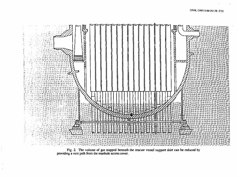
The effectiveness of drywell flooding could be improved if the reactor vessel support skirtwere vented in order to reduce the trapped gas volume and increase the fraction of bottom headsurface area contacted by water. Partial venting could be achieved by loosening the cover on thesupport skirt manhole access. This would increase the covered portion of the bottom head from55% to 73% of the total outer surface area, which delays the predicted time of bottom head creeprupture by about one hour. (The reduced gas pocket for this case is illustrated in Figure 2.) Thepredicted failure times for the basic case without skirt venting and for the case of partial venting atthe manhole access are indicated in the first two entries of Table 2.
Table 2. Effect of skirt venting upon time to failure of the bottomheac pressure boundary for Peach Bottom/Browns Ferry
short-term station blackout with drywell flooding
SkirtVented
No
Partial
Complete
FailureMechanism
Bottom Head Creep Rupture
Bottom Head Creep Rupture
Melting of Upper Vessel Wall
Time toMinutes
780-840
840-900
>1200
FailureHours
13.0- 14.0
14.0 - 15.0
>20.0
Complete venting of the reactor vessel support skirt would provide 100% water coverageof the vessel bottom head but would require special measures such as the drilling of small holes atthe upper end of the skirt, just below the attachment weld. This is not considered to be i practicalsuggestion for the existing BWR facilities, but complete venting might be attainable for theadvanced BWR designs. As indicated by the last entry in Table 2, 100% water coverage of thevessel bottom head would convert the failure mechanism from bottom head creep rupture tomelting of the upper vessel wall and would delay the predicted time of failure to more than 20hours after scram.
ORNL-DWG91M-2517B ETD
I f
Fig. 2. The volume of gas trapped beneath the reactor vessel support skirt can be reduced byproviding a vent path from the manhole access cover.

In summary, all portions of the reactor vessel wall that are covered by water would beadequately protected against failure by melting or creep rupture. For the cases with no venting orpartial venting of the support skirt, the creep rupture failure is predicted to occur in the portion ofthe vessel wall adjacent to the trapped gas pocket beneath the skirt. Partial venting would reducethe size of the gas pocket and delay the predicted time of failure, but the failure mechanism wouldstill be creep rupture beneath the skirt attachment weld. With complete venting, however, therewould be no gas pocket and this failure mechanism would be eliminated.
What cannot be eliminated, however, is the radiative heat transfer upward within the reactorvessel from the surface of the lower plenum debris bed. About one-half to two-thirds of all energyrelease within the bed would be radiated upward after bottom head dryout. Initially, the primaryheat sink for this radiation would be the water trapped in the downcomer region between the coreshroud and the vessel wall above the debris bed. It is the heating of this water that creates the onlysteam source within the reactor vessel after lower plenum dryouL
After the water in the downcomer region became exhausted, the upward radiative heattransfer from the debris surface would serve to increase the temperature of the upper reactor vesselinternal structures. For calculations with the existence of a gas pocket beneath the skirt, bottomhead creep rupture is predicted to occur while the temperature of these internal stainless steel heatsinks remains below the melting point. If bottom head creep rupture did not occur, however, thedebris would remain within the vessel, the upward radiation would continue, and the upper internalstructures would melt.
The mass of the BWR internal structures (core shroud, steam separators, dryers) is large.Melting of these stainless steel structures under the impetus of the upward debris pool radiation(more than 14 hours after scram) would occur over a long period of time. Nevertheless, decayheating of the debris pool and the associated upward radiation would be relentless and, afterexhaustion of the stainless steel, the only remaining internal heat sink above the pool surface wouldbe the carbon steel of the upper vessel wall. All portions of the wall cooled by water on their outersurfaces would remain intact, but those upper portions of the vessel exposed to the drywellatmosphere would ultimately reach failure temperatures.
It should be obvious from this discussion of the effect of water upon cooling of the vesselwall that it would be desirable to have a dr, ..ell flooding strategy that would completely submergethe reactor vessel. This could not be achieved in existing facilities because of the limitation that theheight of water within the drywell cannot exceed the elevation of the drywell vents. Futuredesigns, however, might provide for complete coverage of the reactor vessel as a severe accidentmitigation technique.
Table 3 provides a summary of the calculated failure times and release mechanisms for allof the cases considered in this study. These include the cases previously discussed in connectionwith Tables 1 and 2, plus one additional case (third entry) in which it is assumed that reactorvessel pressure control is lost at the time of drywell flooding, because of the submergence of thesafety/relief valves. [The location of these valves (SRVs) within the Browns Ferry drywell isshown in Figures 3 and 4.] The increased wall tensile stress associated with this case wouldcause the wall creep rupture to occur at a lower temperature, advancing the time of failure by abouttwo hours over the depressurized case (compare the third and fourth entries in Table 3).

-REACTOR VESSEL
MAIN STEAM LINE
RECIRCULATIONPUMP
TORUS ORWETWELL
CONCRETE FLOOROFDRYWELL
VENT PIPE
DOWNCOMER:
PRESSURESUPPRESSIONPOOL
Fig. 3. The reactor vessel safety/relief valves are located on the horizontal runs of the mainsteam lines, near the bottom of the vessel.
I REflCTOR PRESSUREVESSEL
DRYHELL
QUENCHER
Fig. 4. Location of a typical safety/relief valve and its tailpipe within the BWR Mark Icontainment.

Table 3. Effect of drywell flooding upon time of debris release from thereactor vessel for the short-term station blackout accident sequence
based upon Peach Bottom/Browns Ferry
DrywellFlooded
No
No
Yes
Yes
Yes
Yes
SkirtVented
—
—
No
No
Partial
Complete
Reactor VesselDepress urized
Yes
Yes
No
Yes
Yes
Yes
ReleaseMechanism
PenetrationFailures
Bottom HeadCreep Rupture
Bottom HeadCreep Rupture
Bottom HeadCreep Rupture
Bottom HeadCreep Rupture
Melting ofUpper Vessel
Wall
TimetcMinutes
250
600-640
660-700
780-840
840-900
>1200
) FailureHours
4.2
10.0 - 10.7
11.0- 11.7
13.0 - 14.0
14.0 - 15.0
>20.0
The most important disadvantage of a drywell flooding strategy for existing plants is therequirement for venting to the external atmosphere while the containment is being filled by the low-pressure pumping systems and during the subsequent steaming from the water surrounding thereactor vessel bottom head. Because of this, implementation of the drywell flooding strategywould initiate a noble gas release to the surrounding atmosphere as well as a limited escape offission product particulates. All paniculate matter released from the reactor vessel prior to failureof the vessel wall would enter the pressure suppression pool via the safety/relief valve T-quenchersand would be scrubbed by passage through the water in both the werwell and drywell. Therefore,the concentration of particulates in the drywell atmosphere and any release through the drywellvents would remain small as long as the reactor vessel wall remained intact
Creep rupture of the vessel bottom head beneath the support skirt attachment would releasedebris into the water-filled pedestal region to fall downward onto the drywell floor. Sincecontainment flooding would provide a water depth of more than 9 m (30 ft) over the drywellfloor, the paniculate matter released from the debris mass should be adequately scrubbed provided,

of course, that violent steam explosions do not occur. Furthermore, the large volume of water inthe drywell would protect the drywell shell from failure in Mark I containment facilities.
The advantages and disadvantages of a drywell flooding strategy for existing BWRfacilities are summarized in Table 4. The listed advantages involve significant contributions toaccident mitigation, which have previously been discussed. The listed disadvantages, however,are also important and will be discussed in the following paragraphs.
Table 4. Advantages and disadvantages of a drywell flooding strategy forsevere accident mitigation in existing BWR facilities
Advantages
Disadvantages
1. Prevent failure of the bottom head penetrations andvessel drain
2. Increased scrubbing of fission product particulate matter
3. Delay creep rupture of the reactor vessel bottom head
4. Prevent failure of the Mark I drywell shell wLen coredebris does leave the vessel
1. Requires availability of power source and pump capableof filling the drywell to the level of the vessel bottomhead within 150 minutes under station blackoutconditions.
2. Requires that the drywell be vented.
First, implementation of the proposed strategy would require equipment modifications andadditions. Although there may be plant-specific exceptions, containment flooding with the existingpumping systems would require too much rime; furthermore, the existing systems would not beavailable for the dominant station blackout accident sequences. What is needed is a reliable abilityto sufficiently flood the drywell within a short period of time, since it would be unrealistic toexpect that emergency procedures would call for containment flooding (and the associatedundesirable effects upon installed drywell equipment) until after core degradation had begun. If thewater did not reach the vessel bottom head until after lower plenum debris bed dryout and the initialheating of the vessel wall, it would be too late to prevent penetration assembly failures.
The second disadvantage, that the drywell vents would have to be opened to permitflooding of the containment, is particularly undesirable since it would involve early release of thefission product noble gases, beginning soon after the onset of core degradation. After the waterhad contacted the vessel bottom head, a continuous steam generation would begin within the
drywell that would be released to the outside atmosphere by means of the open vents. This wouldtend to sweep any paniculate matter from the drywell atmosphere through the vents. The amountof paniculate matter reaching the drywell atmosphere would, however, be limited by waterscrubbing as long as the reactor vessel wall remained intact above the water level in the drywell.This is expected to be the case for the existing BWR facilities where the ultimate failure of the wallwould occur by creep rupture beneath the skin attachment weld.
It is interesting, however, to briefly consider the potential benefits of application of adrywell flooding strategy to future BWR facilities, where the disadvantages listed in Table 4 mightbe avoided by appropriate plant design. Much less water would be required since the reactorvessel would be located in a cavity instead of suspended high above a flat drywell floor. Provisioncould be made for complete venting of the reactor vessel support skirt so that all of the bottom headwould be in contact with water. This would preclude creep rupture of the vessel bottom head,shifting the potential failure mode to melting of the upper vessel wall, above the water level in thedrywell.
For the existing BWR facilities, failure of the upper reactor vessel wall would provide adirect path from the upper surface of the debris pool to the open drywell vents without the benefitof water scrubbing. This corresponds to the last entry in Table 3, which is based upon completeventing of the vessel support skirt (not considered practical for the existing facilities). For futureplant designs, the potential for a direct release pathway could be avoided in two ways. First,complete vessel submergence would preclude failure of the upper vessel wall. Second, therequirement for containment venting could be eliminated by provision of an adequate water sourcewithin the containment and provision for condensation of the generated steam. Both of theseapproaches are within the scor": of design features currently under consideration for the advancedpassive design.
This study of the effectiveness of drywell flooding is currently documented by letter report(ORNL/NRC/LTR-91/9). However, it is anticipated that these results will be incorporated into aNUREG/CR report during 1992.
3. POISONING THE INJECTION SOURCE
The second recommendation developed as a result of the consideration of candidate mitigativestrategies for in-vessel events during the late phase (after core degradation has occurred) ofpostulated BWR severe accidents addresses the prevention of undesired criticality.
If significant control blade melting and relocation were to occur during a period of temporarycore uncovering, then criticality would follow restoration of reactor vessel injection capability if thecore were rapidly recovered with unborated water using the high-capacity low-pressure injectionsystems. If the relatively slow Standby Liquid Control System (SLCS) were simultaneouslyinitiated to inject sodium pentaborate solution, then the core would remain critical until sufficientboron for shutdown reached the core region. It would be preferable, if control blade melting andrelocation has occurred, to inject only a boron solution provided that this car. be done at a ratesufficient to provide core cooling and terminate core damage.

The specific goal of the proposed strategy is to provide for the addition of the boron-10isotope together with the injected flow being used to recover the core, in sufficient quantity topreclude criticality as the water level rises within the reactor vessel. It is expected that this could beaccomplished using only existing plant equipment. One way to do this would be to mix the borondirectly with the water in the condensate storage tank and then take suction on the condensatestorage tank with the low-pressure system pump to be used for vessel injection. It is, however,not a simple matter to invoke this strategy and preplanning a<id training would be required.
With respect to the rationale for incorporation of this strategy, a recent Pacific NorthwestLaboratory (PNL) report30 establishes that criticality upon reflooding with unborated water islikely for either standing fuel rods or for a debris bed subsequently formed in the core region. It isnot unreasonable that this prediction alone should provide sufficient motivation for incorporation ofa boration strategy since there is a strong potential for operator surprise and confusion should, forexample, a station blackout accident sequence be converted into an ATWS-type sequence uponrestoration of reactor vessel injection capability. However, the PNL report makes the conclusionthat
"— it appears that a super prompt-critical excursion (in which some fuelvaporization, dispersal of molten fuel debris, rapid molten fuel-coolant interaction,and the production of a large pressure pulse capable of directly failing the vesseland/or containment occurs) is not credible under conditions of reflooding a hot,degraded core; even under conditions of maximum reflood rate. Doppler feedback,in itself, appears to be adequate to limit the energetics of reflood recriticality to alevel below which the vessel would be threatened by a pressure pulse. It is morelikely that the reactor would either achieve a quasi-steady power level or enter anoscillatory mode in which water periodically enters and is expelled from the coredebris. In either case, the average power level achieved is determined by thebalance between reactivity added and the feedback mechanisms. Criticality indebris beds will probably produce power levels no larger than 10 to 20 percent ofnormal power. At these levels, the coolant makeup systems could provide adequatecoolant to remove the heat generated within the debris bed."
Thus, one might conclude that the criticality attendant to reflooding could be controlled in thesame manner as an ATWS, that it could be terminated by normal means [use of the SLCS], andthat no dedicated strategy for preventing the criticality is required.
Nevertheless, criticality produced by reflooding after core damage has characteristics verydifferent from those associated with ATWS, including not being addressed by current procedures,the probable lack of nuclear instrumentation, and the factor of operator surprise. The configurationof the critical masses in the core region might be standing fuel rods alone, a combination ofstanding fuel rods (outer core) and debris beds (central core), or a core-wide debris bed.Consultation with Dr. Jose March-Leuba of ORNL, who has recently performed a series of B WRstability calculations31, reveals that there is a potential for much more serious consequences ofcriticality by rapid reflooding than those indicated by the PNL report. While he does notrecommend any further attempts at this time to calculate a power-vs-time profile for refloodingwithout control blades (the state of the art would not permit a definitive result), he does believe thatthe current state of knowledge, based upon available information from previous calculations,supports a conclusion that preventative measures are desirable.

The PNL report provides the estimate that a boron-10 concentration of between 700 and1000 ppm would be required within the reactor vessel to preclude criticality once control blademelting had occurred. The next Section describes the concentration achievable with the SLCS.
3.1 INJECTION WITH THE STANDBY LIQUID CONTROL SYSTEM
The normal means of adding boron to the reactor vessel is by dedicated injection by theStandby Liquid Control System (SLCS). While this system is designed to inject sufficientneutron-absorbing sodium pentaborate solution into the reactor vessel to shut down the reactorfrom full power (independent of any control rod motion) and to maintain the reactor subcriticalduring cooldown to ambient conditions, the SLCS is not intended to provide a backup for the rapidshutdown normally achieved by scram.
As indicated in Figure 5, the basic system comprises a heated storage tank, two 100%capacity positive displacement pumps, and, as the only barrier to injection to the reactor vessel,two explosive squib valves. In most of the current BWR facilities, the sodium pentaboratesolution enters the reactor vessel via a single vertical sparger located at one side of the lowerplenum just below the core plate as indicated in Figures 6 and 7. An effort to improve the mixingand diffusion of the injected solution (which has a specific gravity of about 1.3) throughout thecore region has lead some BWR facilities to provide a third positive displacement pump and tocause the injected solution to enter the reactor vessel via the core spray line and sparger.
For the purpose of reducing the time required for reactor shutdown for the ATWS accidentsequence, the NRC has recently required that the SLCS injection be at a rate equivalent to 86 gpmof 13-weight percent sodium pentaborate solution, the boron being in its natural state with 19.8atom percent of the boron-10 isotope.* This requirement is established by the "ATWS rule,"which states, in part:
"Each boiling water reactor must have a standby liquid control system (SLCS)wiih a minimum flow capacity and boron content equivalent in control capacity to86 gallons per minute of 13-weight percent sodium pentaborate solution."32
Since the original SLCS standard design provided for single-pump operation at a rate of43 gpm, the ATWS rule permits the requirement for the increased equivalent control capacity to besatisfied by simultaneous operation of both of the installed pumps, by increasing the concentrationof sodium pentaborate solution, or by enriching the boron within the sodium pentaborate solutionin the isotope boron-10. Different BWR facilities have taken different approaches.
The sodium pentaborate solution is normally prepared by dissolving stoichiometric quantitiesof borax and boric acid within hot demineralized water according to the reaction**
Na2B4O7 • 10H2O + 6H3BO3 -» Na2B10Oi6 • 10H2O + 9H2O.
As an illustrative example based upon a representative volume of the standby liquid controlsolution tank, 4076 lbs of borax and 3963 lbs of boric acid crystals dissolved within
* It is the jB 1 0 isotope thai has the large absorption cross section (3840 barns). The reaction is5B )0 +on1 -> jLi' + jHe*.
** As written, the reaction shows equivalent sodium pentaborate as a product.

SERVICt*M
CHEMICALADIIiriON
AND SAMPLEMATCH
DCMIN.WATgft
SLCSTOHAOE
TANK
CLECTRICHEATED |
-AAA/4
^pr LO
LO
SLCPUMP
A
ACCUMULATOR
LO
ACCUMULATOR/
CKJ
LO
SLCPUMP
B
SPOOLPIECt
LO
REACIOflVESSEL
o •
cLO
it o .
EXPLOSIVEVALVE
EXPLO3I«VALVE
Fig. 5. Abbreviated schematic of the typical BWR standby liquid control system (SLCS). Forclarity, all piping exclusively dedicated to system testing has been deleted from this drawing.

OHNL-DWO 84-4624 6TD
••OKICOM /ri>TE IMP s
IT»NM» UCOIOCOHTKOL
SHROUD
INCOAE INSTRUMENTHOUSINGS
Fig. 6. Location of standby liquid control systeminjection sparger within the BWR-4 reactor vessei.
Fig. 7. The differential pressure and standby liquidcontrol system injection line enters th« reactor vessel as twoconcentric pipes, which separate in tl»e lower plenum. Theinner pipe, which terminates with a perforated length belowthe core plate is used during normal operation to sense thebelow-olate pressure and is used for sodium pentaborateinjection when required. The outer pipe terminatesimmediately above the core plate and senses the pressure inthe interstitial region of the core.

4608 gallons of water will produce an aqueou» solution containing 6305 lbs of sodiumpentaborate. This is 13.6% sodium pentaborate by weight. The tank contains 1155 lbs of boronand, assuming that the boron is in its natural state (not enriched), 228.5 lbs of the boron-10isotope.
Continuing the example, the SLC tank contains 46,360 lbs of solution so the concentrationof natural boron within the tank would be 24,900 ppm. Since the mass of water within the reactorvessel (at normal water level and operating temperature) is 628,300 lbs,** the concentration ofnatural boron within the reactor vessel after the contents of the SLC tank had been added would beapproximately 1840 ppm (the concentration of the boron-10 isotope would be abc it 360 ppm).
After the reactor had been brought subcritical, thft next steps toward complete shutdownwould involve cooldown and vessel filling. The reactor vessel water mass with normal water levelat 70°F would be 850,000 lbs so that water addition during cooldown would reduce theconcentration of natural boron to 1360 ppm. Finally, with the vessel completely filled aftercooldown, the water mass would be 1,400,000 lbs and the natural boron concentration would be825 ppm. With the boron in its natural state, the concentration of the boron-10 isotope would be163 ppm, which is sufficient to maintain the core shutdown in the cold, xenon-free condition.
Thus, the basic operational concept of the SLCS for ATWS control is that the very highconcentration of boron in the relatively small SLC tank is diluted to the desired value when pumpedinto the much larger reactor vessel and mixed with the vessel water inventory.
Where BWR facilities have chosen to enrich the sodium pentaborate solution in the boron-10isotope rather than to increase the pumping rate, it is the boric acid constituent that is enriched,typically to 92 atom percent. This approach maintains the SLCS redundancy of having twopumps capable of independent operation.
Under severe accident conditions, injection of neutron poison may be required for a situationvery different than that normally associated with ATWS. If significant control blade melting andrelocation from the core region were to occur during a period of temporary core uncovering, thencriticality should be expected if reactor vessel injection capability is restored and the core is thencovered with cold unborated water.30 This situation is most likely to occur with restoration ofelectrical power after a period of station blackout. If the SLCS were used to inject the sodiumpentaborate solution at a relatively slow rate while the core was rapidly covered using the high-capacity low-pressure injection systems, then criticality would occur and the core would remaincritical until sufficient boron for shutdown reached the core region.
It would be preferable, if control blade melting and relocation has occurred, to reflood thevessel from an injection source such as the condensate storage tank containing a premixed solutionof neutron poison so that there would be no threat of criticality as the core was recovered. Thismust be achievable, however, at a rate sufficient to provide immediate core cooling and, thereby,terminate core damage. The major diagnostic concern with respect to this strategy is that theoperators would have no direct means of knowing whether or not significant control blade meltingand relocation had occurred Therefore, either the injection source would have to be poisoned afterany non-trivial period of core uncovering or reliance would have to be made on precalculatedvalues of time to control blade melting for the various accident situations.
** Water mass for a 251-inch ID BWR 3/4 reactor vessel, including the recirculaiion loops at the hot ratedcondition.

3.2 AN ALTERNATIVE METHOD OF FORMING THE POISON SOURCE
On two counts, operation of the SLCS would not prevent criticality upon vessel refloodfollowing a period of temporary core uncovering with control blade melting. First, the injection ofpoison by this system would be too slow. Second, the amount of poison injected would beinsufficient Based upon the recent PNL analysis,30 a concentration of 700-1000 ppm of theboron-10 isotope would be required to ensure that criticality would not occur as the damaged corewas covered. As discussed in Section 3.1, the concentration provided by operation of the SLCSis less than 200 ppm.
In addition, formation of sodium pentaborate by the normal method of separately addingborax and boric acid crystals would not be feasible at low temperatures and without mechanicalmixing. Information concerning an alternative boron form was obtained by contacting the U.S.Borax Company at Montvale, NJ. The Company produces a disodium octaborate tetrahydrate(Na2BgOi3 • 4H2O) in readily soluble powder form, under the tradename Polybor. Boronconstitutes 20.97% of the total weight of Polybor, as opposed to 18.32% of the weight of sodiumpentaborate. Using Polybor, the total amount of material needed to form a given concentration ofnatural boron is significantly (about one-third) less than for borax and boric acid. For example,preparation of a concentration of 24,900 ppm within 4,608 gallons of water (as in the example ofSection 3.1) would require the addition of 8,039 lbs of borax and boric acid, but only 5,171 lbsof Polybor. Much of the difference lies in the excess water added with the borax(Na2B4O7 • 10H2O).
The chief industrial use of Polybor is for fire retardant treatment of lumber by heavy sprayapplication or by immersion of decorative and other cellulosic materials. It readily dissolves inwater, forming supersaturated solutions. The following Table, supplied by the U.S. BoraxCompany, indicates its superior solubility (under equilibrium conditions) in water.
Table 5. Solubility of Polybor in water and correspondingconcentrations of B2O3 compared with Borax
at the same temperature
TemperatureK °F
111
283
293
303
313
323
333
348
367
32
50
68
86
104
122
140
167
201
weight %Polybor
2.4
4.5
9.5
21.9
27.8
32.0
35.0
39.3
45.3
% Concentration of B2O3in saturated solutions of:
Polybor Borax
1.6
3 0
6.3
14.5
18.4
21.2
23.2
26.0
30.0
0.73
1.13
1.72
2.63
4.10
6.54
11.07
14.67
21.00

Polybor dissolves even in cool water to give supersaturated solutions of considerably higherconcentration than indicated in Table 5. Simple table-top experiments at Oak Ridge havedemonstrated that Polybor dissolves much more readi'y in water than does the normally usedmixture of borax and boric acid crystals. (There is no need for two separate powders to interact inthe case of Polybor.) This is of interest because the accident management strategy underconsideration must be capable of use under station blackout conditions, when the water in thecondensate storage tank may have cooled significantly at the time the borated solution was to beprepared and mechanical mixing of the tank contents would not be available.
3.3 PREPARING THE INJECTION SOURCE
The condensate storage tank is an important source of water to the reactor vessel injectionsystems. As indicated in Figure 8 (based upon the Browns Ferry arrangement), it is the normalsuction source for the steam turbine-driven high pressure coolant injection (HPCI) and reactor coreisolation cooling (RCIC) systems and the alternate source for the electric motor-driven residual heatremoval (RHR) and core spray (CS) pumps. Other BWR facilities also have at least one motor-driven reactor vessel injection system capable of taking suction upon the condensate storage tank(CST). At least one BWR facility currently has in place a procedure for adding borax and boricacid crystals directly to the (partially drained) CST, for use as backup to the SLCS if needed in theevent of ATWS.33
As discussed previously, a much higher concentration of boron would be required for theprevention of criticality for the case of a degraded core than would be required for the control ofATWS. The requirement stated in Reference 30 is for a concentration of 700-1000 ppm of theboron-10 isotope, which is 4 to 6 times greater than the reactor vessel concentration (163 ppm)obtained by operation of the SLCS.
During normal reactor operation, the CST provides makeup flow to the main condenserhotwells via an internal tank standpipe, as indicated on Figure 9. Any practical strategy for directpoisoning of the CST must provide for partial draining of this tank, particularly if boron-10concentrations greater than 700 ppm are to be achieved. The CST could be gravity-drainedthrough the standpipe under station blackout conditions. The residual water volume would beplant-specific, but a representative value for a 1060 MWe BWR-4 facility such as Browns Ferry is135,000 gal (511 m3).
Even with partial CST draining, however, the amount of powder required to obtain aboron-10 concentration of 1000 ppm is large. Assuming the use of Polybor to take advantage ofits greater solubility, 27,775 lbs (12,600 kg) would have to be added to the partially drained tank.[If borax/boric acid were used, the requirement would be 41,000 lbs (18,600 kg).] Clearly, thisis too much to be manhandled [50-lb (23-kg) bags] to the top of the tank and poured in. Thepractical way to poison the CST would be to prepare a slurry of extremely high concentration in asmaller tank at ground level; then to pump the contents of this small tank into the upper opening ofthe CST. (As indicated in Table 5, extremely high concentrations can be achieved with Polybor.)To avoid any requirement for procurement of additional plant equipment, a fire engine with itsportable suction tank might be employed to perform the pumping function.

ORNl-DWG 83-5616 0TDNORMAL SOURCEALTERNATE SOURCE
-RECIRCULATIONPUMP
•RHR HEATf EXCHANGERS (4)
CRDHYDRAULIC _ _
PUMPRHR
(4 PUMPSjl
CORE SPRAY(« PUMPS)
Fig. 8. The condensate storage tank is an important source of water for use in accidentsequences other than large-break LOCA.
R ( RHRSW r 1(-
RHR
» TO FWI TURBI^C
TURBINE
Fig. 9. The condensate storage tank can be drained to the main condenser hotwells via theinternal standpipe, leaving a sufficient volume for reactor vessel injection.

4. SUMMARY
A recently completed Oak Ridge effort proposes two management strategies for mitigation ofthe events that might occur in-vessel after the onset of significant core damage in a BWR severeaccident. While the probability of such an accident is extremely low, there may be-effective yetinexpensive mitigation measures that could be implemented employing the existing plant equipmentand requiring only additions to the plant emergency procedures. In this spirit, accidentmanagement strategies have been proposed for use of a borated solution for reactor vessel refillshould control blade damage occur during a period of temporary core dryout and for containmentflooding to maintain the core debris within the reactor vessel if the injection systems cannot berestored.
The proposed severe accident management strategy for poisoning of the water used for vesselreflood should injection systems be restored after control blade damage has occurred has greatpromise for practical implementation. It could be accomplished using only the existing plantequipment but employing a different chemical form for the boron poison. Available informationconcerning the poison concentration required indicates that much more boron would have to beinjected than is available in the Standby Liquid Control System. Furthermore, the dominant BWRsevere accident sequence is Station Blackout and without means for mechanical stirring or heatingof the injection source, the question of being able to form the poisoned solution under accidentconditions becomes of supreme importance. Hence the need for the alternate chemical form.
On the other hand, the proposed strategy for drywell flooding to cool the reactor vesselbottom head and prevent the core and structure debris from escaping to the drywell holds lesspromise. Although drywell flooding would preclude bottom head penetration failures and therebygreatly delay the release of debris, the bottom head would eventually fail by creep rupture. This isa consequence of not being able to completely surround the bottom head with water because of thegas pocket that would be trapped beneath the vessel support skirt Since the drywell vents wouldhave to remain open during and after the flooding process, the ultimate failure of the vessel wallwould open a direct pathway for escape of fission products to the atmosphere. This strategy does,however, have potential for future plant designs for which gas release pathways might be providedfor the vessel skirt and passive methods might be employed to completely submerge the reactorvessel under severe accident conditions without the need for containment venting.
5. REFERENCES
1. Greene, S. R., Realistic Simulation of Severe Accidents in BWRs - ComputerModeling Requirements, NUREG/CR-2940, ORNL/TM-8517, Oak Ridge National Laboratory,April 1984.
2. Ott, L. J., "Advanced Severe Accident Response Models for BWR Application,"Nuclear Engineering and Design, No. 115,1989, p. 289-303.
3. Hodge, S. A., "Thermalhydraulic Processes in the Reactor Coolant System of aBWR Under Severe Accident Conditions," Procsedings, ICHMT International Seminar on Heatand Mass Transfer Aspects of Fission Product Releases, Dubrovnik, Yugoslavia, May 1989.
4. Hodge, S. A., "BWR Reactor Vessel Bottom Head Failure Modes," Proceedings,ICHMT International Seminar on Heat and Mass Transfer Aspects of Fission Product Releases,Dubrovnik, Yugoslavia, May 1989.
5. Hodge, S. A. and Harrington, R. M., Considerations Regarding Certain Aspects ofSevere Accident Mitigation Afforded by Operation of Shoreham at Reduced Power, letter repon.(ORNL/M-1011) to Mr. S. Singh Bajwa, Risk Applications Branch, NRR, USNRC, dated June12, 1987.
6. Hodge, S. A., Hyman, C. R., and Ott, L. J., Boiling Water Reactor SevereAccident Technology at Oak Ridge - Purpose and Goals -, letter repon (ORNL/M-1017) toDr. Thomas J. Walker, Accident Evaluation Branch, Division of Systems Research, RES,USNRC, dated December 6, 1988.
7. Severe Accident Risks: An Assessment for Five U.S. Nuclear Power Plants,NUREG-1150, December 1990.
8. Cook, D. H. et al., Station Blackout at Browns Ferry Unit One - AccidentSequence Analysis, Vol. 1, NUREG/CR-2182, ORN1VNUREG/TM-455/V1, November 1981.
9. Wichner, R. P. et al., Station Blackout at Browns Ferry Unit One - Iodine andNoble Gas Distribution and Release, Vol. 2, NUREG/CR-2182, ORNL/NUREG/TM-455/V2,August 1982.
10. Condon, W. A. et al., SBLOCA Outside Containment at Browns Ferry Unit One -Accident Sequence Analysis, Vol. 1, NUREG/CR-2672, ORNI7TM-8119/V1, October 1982.
11. Wichner, R. P. et al., SBLOCA Outside Containment at Browns Ferry Unit One -Iodine, Cesium, and Noble Gas Distribution and Release, Vol. 2, NUREG/CR-2672, ORNL/TM-8119/V2, September 1983.
12. Cook, D. H. et al., Loss ofDHR Sequences at Browns Ferry Unit One - AccidentSequence Analysis, Vol. 1, NUREG/CR-2973, ORNL/TM-8532, May 1983.
13. Harrington, R. M. and Ott, L. J,, The Effect of Small-Capacity, High-PressureInjection Systems on TQUV Sequences at Browns Ferry Unit One, NUREG/CR-3179,ORN1/TM-8635, September 1983.
14. Harrington, R. M. and Hodge, S. A., ATWS at Browns Ferry Unit One - AccidentSequence Analysis, NUREG/CR-3470, ORNL/TM-8902, July 1984.
15. Wichner, R. P. et al., Noble Gas Iodine, and Cesium Transport in a PostulatedLoss of Decay Heat Removal Accident at Browns Ferry, NUREG/CR-3617, ORNL/TM-9028,August 1984.
16. Harrington, R. M., Evaluation of Operator Action Strategies for Mitigation ofMSIV-Closure Initiated ATWS, letter report to Dr. Thomas J. Walker, Accident EvaluationBranch, Division of Systems Research, RES, USNRC, dated November 11,1985.
17. Harrington, R. M., The Effect of Reactor Vessel Pressure and Water Level onEquilibrium BWR Core Thermal Power During MSIV-Closure-Initiated ATWS, letter report toDr. Thomas J. Walker, Accident Evaluation Branch, Division of Systems Research, RES,USNRC, dated January 10,1986.
18. Harrington, R. M. and Hodge, S. A., Loss of Control Air at Browns Ferry UnitOne - Accident Sequence Analysis, NUREG/CR-4413, ORNL/TM-9826, January 10, 1986.
19. Harrington, R. M. and Hodge, S. A., Containment Venting as a Severe AccidentMitigation Technique for BWR Plants with Mark 1 Containment, letter report to Dr. Thomas J.Walker, Accident Evaluation Branch, Division of Systems Research, RES, USNRC, datedJune 26, 1986.
20. Ott, L. J. and Hodge, S. A., Modeling of Time-Dependent Emergence of CoreDebris from a Boiling Water Reactor Under Severe Accident Conditions, letter report (ORNL/M-

1015), to Dr. Thomas J. Walker, Accident Evaluation Branch, Division of Systems Research,RES, USNRC, dated April 22, 1988.
21. Hodge, S. A., Failure Modes of the BWR Reactor Vessel Bottom Head, letterreport (ORNL/M-1019), to Dr. Thomas J. Walker, Accident Evaluation Branch, Division ofSystems Research, RES, USNRC, dated May 10, 1989.
22. Hodge, S. A. and Git, L. J., "BWRSAR Calculations of Reactor Vessel DebrisPours for Peach Bottom Short-Term Station Blackout," Nuclear Engineering and Design, No.121, 1990, p. 327-339.
23. BWR Owners' Group Emergency Procedure Guidelines, Revision 4, GeneralElectric Topical Report NEDO-31331, March 1987.
24. Lucas, W. J., Vandenkieboom, J. J., and Lehner, J. R., Assessment of CandidateAccident Management Strategies, NUREG/CR-5474, BNL-NUREG-52221, March 1990.
25. Hodge, S. A., Accident Management jor Critical BWR Severe AccidentSequences-Assessment of Current Status, letter report ORNL/NRC/LTR-90/12 to Dr. James T.Han, Reactor and Plant Systems Branch, Division of Systems Research RES, USNRC, May 31,1990.
26. Hodge, S. A., BWR (In-Vessel) Late Accident Mitigation Strategies, lettfr reportORNL/NRC/LTR-90/18 to Dr. James T. Han, Reactor and Plant Systems Branch, r\v i sion ofSystems Research, RES, USNRC, September 15, 1990.
27. Hodge, S. A., Recommendations for Further Assessment of Certain BWR (!n-Vessel) Late Accident Mitigation Strategies, letter report ORNL/NRC/LTR-90/19 to Dr. James T.Han, Reactor and Plant Systems Branch, Division of Systems Research, RES, USNRC,September 25,1990.
2 8. Individual Plant Examination for Severe Accident Vulnerabilities - 10CFR50J4(f),USNRC Generic Letter No. 88-20, November 23,1988.
29. Individual Plant Examination: Submittal Guidance, NUREG-I335, USNRC, FinalReport, August 1989.
30. Scott, W. B., et al., Recriticality in a BWR Following a Core Damage Event,NUREG/CR-5653, PNL-7476, December 1990.
31. March-Leuba, J., Stability Calculations for the Grand Gulf-I and Susquehanna-2Boiling Water Reactors, letter report (ORNL/NRC/LTR-87/08) to Mr. T. L. Huang, Office ofNuclear Reactor Regulation, USNRC, September 1987.
32. 10 CFR 50.62, Requirements for Reduction of Risk from Anticipated TransientsWithout Scram (ATWS) Events for Light-Water-Cooled Nuclear Power Plants, Paragraph (c) (4).
33. NRC Inspection Report No. 50-416191-02, enclosure to letter fromThomas A. Peebles, Chief Operations Branch, Division of Reactor Safety to Mr. W. T. Cottle,Vice President Operations-Grand Gulf, Entergy Operations, Inc., Subject: NRC Inspection ReportNo. 50-416/91-02, dated Feoruary 14, 1991.


![IA conf QRT 2802-v3[2]](https://img.pdfslide.net/doc/110x75/62025ebf15fda437256e43fc/ia-conf-qrt-2802-v32.jpg)