Embed Size (px)
Citation preview

C-C
F-20
17 ©
2017
SIM
PS
ON
STR
ON
G-T
IE C
OM
PAN
Y IN
C.
Connectors for Cold-Formed Steel Construction
47
FCB Bypass Framing Fixed-Clip Connector
The FCB clip is an economical, high-performance fixed-clip connector that can be used for a variety of framing applications. It is rated for tension, compression, shear and in-plane loads and offers the Designer the flexibility of specifying different screw and anchorage patterns that conform to desired load levels.
Features:
• Rated for tension, compression, shear and in-plane loads
• Provides design flexibility with varying screw and anchorage patterns that achieve different load levels
• Strategically placed stiffeners, embossments and anchor holes maximize connector performance
Material: 54 mil (16 ga.)
Finish: Galvanized (G90)
Installation:
• Use the specified type and number of anchors.
• Use the specified number of #12 self-drilling screws to CFS framing. Note that #10 self-drilling screws can be used per the load tables given on pp. 54, 55.
Codes: See p. 11 for Code Reference Key Chart
Ordering Information:
FCB43.5-R25, FCB45.5-R25, FCB47.5-R25, FCB49.5-R25, and FCB411.5-R25 contain:
• Box of 25 connectors (screws not included)
Typical FCB Installation for Roof Rafters
F2 F3
F4
Typical FCB Installation at Bypass Framing
F2F3
F4 F1
Typical FCB Installation at the Base of a 6" Jamb Stud
F2 F3
F4
Typical FCB Installation at Sprandrel Studs and Kickers
F4
F2F3
F3 F2
F1
F4
FCB43.5
FCB45.5
FCB47.5U.S. Patent 8,555,592
FCB49.5
FCB411.5
This product is preferable to similar connectors because of a) easier installation, b) higher loads, c) lower installed cost, or a combination of these features.
Rig
id C
onn
ecto
rs
C-C
F-20
17 ©
2017
SIM
PS
ON
STR
ON
G-T
IE C
OM
PAN
Y IN
C.
Connectors for Cold-Formed Steel Construction
48
FCB Bypass Framing Fixed-Clip Connector
½" min.
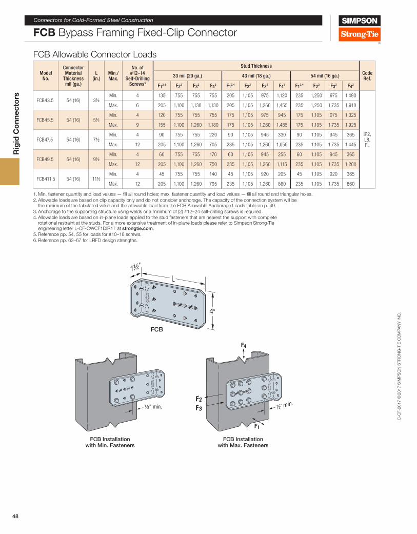
FCB Installation with Min. Fasteners
F2F3
F4
F1
½ min."
FCB Installation with Max. Fasteners
FCB Allowable Connector Loads
Model No.
Connector Material
Thickness mil (ga.)
L (in.)
Min./ Max.
No. of #12–14
Self-Drilling Screws5
Stud ThicknessCode Ref.33 mil (20 ga.) 43 mil (18 ga.) 54 mil (16 ga.)
F13,4 F22 F32 F42 F13,4 F22 F32 F42 F13,4 F22 F32 F42
FCB43.5 54 (16) 3½Min. 4 135 755 755 755 205 1,105 975 1,120 235 1,250 975 1,490
IP2, L8, FL
Max. 6 205 1,100 1,130 1,130 205 1,105 1,260 1,455 235 1,250 1,735 1,910
FCB45.5 54 (16) 5½Min. 4 120 755 755 755 175 1,105 975 945 175 1,105 975 1,325
Max. 9 155 1,100 1,260 1,180 175 1,105 1,260 1,485 175 1,105 1,735 1,925
FCB47.5 54 (16) 7½Min. 4 90 755 755 220 90 1,105 945 330 90 1,105 945 365
Max. 12 205 1,100 1,260 705 235 1,105 1,260 1,050 235 1,105 1,735 1,445
FCB49.5 54 (16) 9½Min. 4 60 755 755 170 60 1,105 945 255 60 1,105 945 365
Max. 12 205 1,100 1,260 750 235 1,105 1,260 1,115 235 1,105 1,735 1,200
FCB411.5 54 (16) 11½Min. 4 45 755 755 140 45 1,105 920 205 45 1,105 920 365
Max. 12 205 1,100 1,260 795 235 1,105 1,260 860 235 1,105 1,735 860
1. Min. fastener quantity and load values — fill all round holes; max. fastener quantity and load values — fill all round and triangular holes.2. Allowable loads are based on clip capacity only and do not consider anchorage. The capacity of the connection system will be
the minimum of the tabulated value and the allowable load from the FCB Allowable Anchorage Loads table on p. 49.3. Anchorage to the supporting structure using welds or a minimum of (2) #12–24 self-drilling screws is required.4. Allowable loads are based on in-plane loads applied to the stud fasteners that are nearest the support with complete
rotational restraint at the studs. For a more extensive treatment of in-plane loads please refer to Simpson Strong-Tie engineering letter L-CF-CWCF1DIR17 at strongtie.com.
5. Reference pp. 54, 55 for loads for #10–16 screws. 6. Reference pp. 63–67 for LRFD design strengths.
Rigid Connectors
4"
1½"
L
FCB
Rig
id C
onn
ecto
rs
C-C
F-20
17 ©
2017
SIM
PS
ON
STR
ON
G-T
IE C
OM
PAN
Y IN
C.
Connectors for Cold-Formed Steel Construction
49
FCB Bypass Framing Fixed-Clip Connector
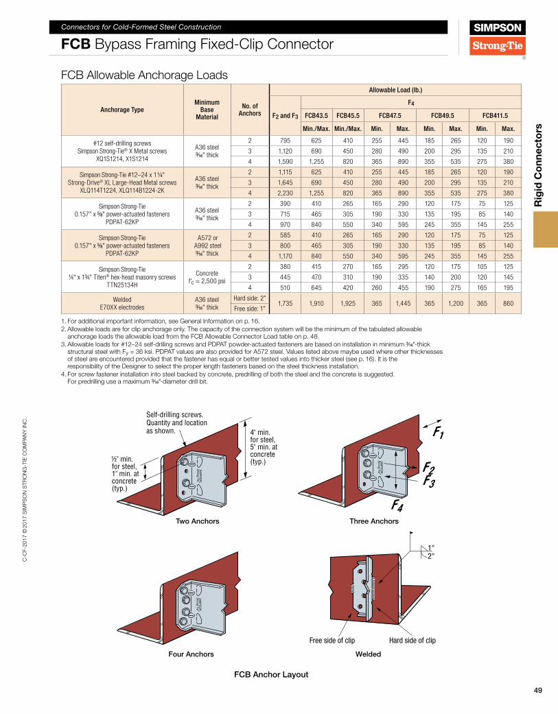
Four Anchors
1"2"
Hard side of clipFree side of clip
Welded
Self-drilling screws. Quantity and location as shown.
½" min. for steel, 1" min. at concrete (typ.)
4" min. for steel, 5" min. at concrete (typ.)
Two Anchors
FCB Anchor Layout
F2F3
F4
F1
Three Anchors
FCB Allowable Anchorage Loads
Anchorage TypeMinimum
Base Material
No. of Anchors
Allowable Load (lb.)
F2 and F3
F4
FCB43.5 FCB45.5 FCB47.5 FCB49.5 FCB411.5
Min./Max. Min./Max. Min. Max. Min. Max. Min. Max.
#12 self-drilling screws Simpson Strong-Tie® X Metal screws
XQ1S1214, X1S1214
A36 steel 3/16" thick
2 795 625 410 255 445 185 265 120 190
3 1,120 690 450 280 490 200 295 135 210
4 1,590 1,255 820 365 890 355 535 275 380
Simpson Strong-Tie #12–24 x 1 1/4" Strong-Drive® XL Large-Head Metal screws
XLQ114T1224, XLQ114B1224-2K
A36 steel 3/16" thick
2 1,115 625 410 255 445 185 265 120 190
3 1,645 690 450 280 490 200 295 135 210
4 2,230 1,255 820 365 890 355 535 275 380
Simpson Strong-Tie 0.157" x 5/8" power-actuated fasteners
PDPAT-62KP
A36 steel 3/16" thick
2 390 410 265 165 290 120 175 75 125
3 715 465 305 190 330 135 195 85 140
4 970 840 550 340 595 245 355 145 255
Simpson Strong-Tie 0.157" x 5/8" power-actuated fasteners
PDPAT-62KP
A572 or A992 steel 3/16" thick
2 585 410 265 165 290 120 175 75 125
3 800 465 305 190 330 135 195 85 140
4 1,170 840 550 340 595 245 355 145 255
Simpson Strong-Tie ¼" x 1¾" Titen® hex-head masonry screws
TTN25134H
Concrete f'c = 2,500 psi
2 380 415 270 165 295 120 175 105 125
3 445 470 310 190 335 140 200 120 145
4 510 645 420 260 455 190 275 165 195
Welded E70XX electrodes
A36 steel 3/16" thick
Hard side: 2”1,735 1,910 1,925 365 1,445 365 1,200 365 860
Free side: 1”
1. For additional important information, see General Information on p. 16.2. Allowable loads are for clip anchorage only. The capacity of the connection system will be the minimum of the tabulated allowable
anchorage loads the allowable load from the FCB Allowable Connector Load table on p. 48. 3. Allowable loads for #12–24 self-drilling screws and PDPAT powder-actuated fasteners are based on installation in minimum 3/16"-thick
structural steel with Fy = 36 ksi. PDPAT values are also provided for A572 steel. Values listed above maybe used where other thicknesses of steel are encountered provided that the fastener has equal or better tested values into thicker steel (see p. 16). It is the responsibility of the Designer to select the proper length fasteners based on the steel thickness installation.
4. For screw fastener installation into steel backed by concrete, predrilling of both the steel and the concrete is suggested. For predrilling use a maximum 3/16"-diameter drill bit.
Rig
id C
onn
ecto
rs

C-C
F-20
17 ©
2017
SIM
PS
ON
STR
ON
G-T
IE C
OM
PAN
Y IN
C.
Connectors for Cold-Formed Steel Construction
50
FCB Supplemental Information
The following FCB supplemental information is given to help Designers with value-engineered solutions for our FCB connectors. Loads are given for fastener patterns other than our standard “min.” (fill all round holes) and “max.” (fill all round and triangle holes). In addition, the tables give LRFD loads and loads for #10 screws as well as #12 screws.
Table 1: FCB Screw Patterns
SIM
PSON
Stro
ng-T
ie
SIM
PSON
Stro
ng-T
ie
SIM
PSON
Stro
ng-T
ie
SIM
PSON
Stro
ng-T
ie
SIM
PSON
Stro
ng-T
ie
SIM
PSON
Stro
ng-T
ie
SIM
PSON
Stro
ng-T
ie
SIM
PSON
Stro
ng-T
ie
SIM
PSON
Stro
ng-T
ie
SIM
PSON
Stro
ng-T
ie
SIM
PSON
Stro
ng-T
ie
SIM
PSON
Stro
ng-T
ie
SIM
PSON
Stro
ng-T
ie
SIM
PSON
Stro
ng-T
ie
SIM
PSON
Stro
ng-T
ie
SIM
PSON
Stro
ng-T
ie
SIM
PSON
Stro
ng-T
ie
SIM
PSON
Stro
ng-T
ie
SIM
PSON
Stro
ng-T
ie
SIM
PSON
Stro
ng-T
ie
SIM
PSON
Stro
ng-T
ie
SIM
PSON
Stro
ng-T
ie
SIM
PSON
Stro
ng-T
ie
SIM
PSON
Stro
ng-T
ie
Pattern “Min.” Pattern “Max.”
Pattern “Min.” Pattern “Max.”Pattern 1 Pattern 2
FCB43.5
FCB45.5
FCB47.5
FCB49.5
FCB411.5
Pattern “Min.”
Pattern “Min.”
Pattern “Min.”
Pattern 9
Pattern 13 Pattern 14
Pattern 10
Pattern 11 Pattern 12
Pattern 7 Pattern 8
Pattern “Max.”
Pattern “Max.”
Pattern “Max.”
Pattern 3 Pattern 4 Pattern 5 Pattern 6
Rig
id C
onn
ecto
rs

C-C
F-20
17 ©
2017
SIM
PS
ON
STR
ON
G-T
IE C
OM
PAN
Y IN
C.
Connectors for Cold-Formed Steel Construction
51
FCB Supplemental Information
Footnotes for Tables 2, 3, 4 and 51. Calculated values are per AISI RP15-2, AISI S-100, or generally accepted industry standards.
Shaded values for #12–14 screws are tabulated in this catalog and are based on testing per ICC-ES AC261. For #12–14 screws unshaded tabulated values are conservatively based on the maximum value from calculations and from the minimum (4-screw) tested values.
2. The tabulated values do not account for anchorage to the support. Anchor strength must be calculated separately and may reduce the capacity of the connection when compared to the tabulated values.
3. Tabulated values do not include shear, web crippling, buckling or other local effects in the member. The Designer must check member limit states separately.
4. For load combinations that include F1 and/or F2 and/or F3, use an appropriate interaction equation.
5. #10–16 screws shall have Pss ≥ 1,620 lb. #12–14 screws shall have Pss ≥ 2,520. Calculated values are per AISI S-100. Screws must be installed with three (min.) exposed threads.
6. The number of screws listed is for one clip leg that is attached to the supported stud.
7. For the minimum screw pattern, fill all round holes. For the maximum screw pattern fill all round and triangle holes. Reference Table 1 on p. 50.
8. Reference p. 48 for load direction definitions.
9. In addition to calculations of net and gross section tension, and screw shear of the clip leg attached to the stud, F2 values are also calculated for weak-axis bending of the anchored clip leg with the line of bending at the holes farthest from the bend radius of the angle. The Designer is responsible for calculating pull-over, pullout and tension strength of the anchors and this may reduce F2 strength compared to the tabulated values.
10. F3 values are computed using the plate buckling provisions of AISI RP15-2.
11. For the F4 values it is assumed that all of the connection eccentricity is taken by screws in the supported stud. F4 values are also limited by plate shear buckling per AISI RP15-2. The Designer is responsible for calculating the shear capacity of the anchorage which may reduce F4 strength compared to the tabulated values.
12. In addition to the limit states given in notes 9, 10 and 11, F2, F3 and F4 are also limited by screw shear according to the thinnest connected part of the connector and stud.
13. Where test data is not available, service load limits for F2 and F3 are not given since there are no generally accepted industry methods available to compute these values. Calculated F4 service load limits are based on AISI Research Report RP15-2 for 1⁄8" deflection.
14. For 50 ksi studs, 68 mil (14 ga.) and thicker, use tabulated values for 54 mil (16 ga.) — 50 ksi studs.
Rig
id C
onn
ecto
rs
C-C
F-20
17 ©
2017
SIM
PS
ON
STR
ON
G-T
IE C
OM
PAN
Y IN
C.
Connectors for Cold-Formed Steel Construction
52
FCB Supplemental Information
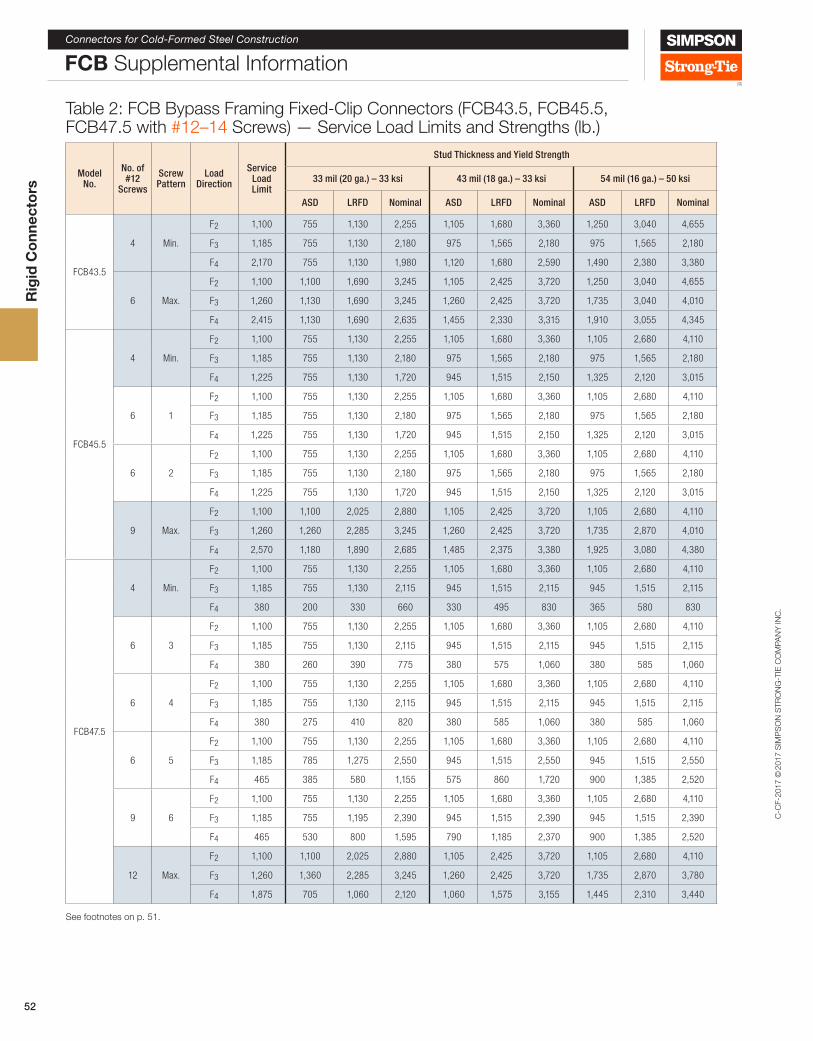
Table 2: FCB Bypass Framing Fixed-Clip Connectors (FCB43.5, FCB45.5, FCB47.5 with #12–14 Screws) — Service Load Limits and Strengths (lb.)
Model No.
No. of #12
Screws
Screw Pattern
Load Direction
Service Load Limit
Stud Thickness and Yield Strength
33 mil (20 ga.) – 33 ksi 43 mil (18 ga.) – 33 ksi 54 mil (16 ga.) – 50 ksi
ASD LRFD Nominal ASD LRFD Nominal ASD LRFD Nominal
FCB43.5
4 Min.
F2 1,100 755 1,130 2,255 1,105 1,680 3,360 1,250 3,040 4,655
F3 1,185 755 1,130 2,180 975 1,565 2,180 975 1,565 2,180
F4 2,170 755 1,130 1,980 1,120 1,680 2,590 1,490 2,380 3,380
6 Max.
F2 1,100 1,100 1,690 3,245 1,105 2,425 3,720 1,250 3,040 4,655
F3 1,260 1,130 1,690 3,245 1,260 2,425 3,720 1,735 3,040 4,010
F4 2,415 1,130 1,690 2,635 1,455 2,330 3,315 1,910 3,055 4,345
FCB45.5
4 Min.
F2 1,100 755 1,130 2,255 1,105 1,680 3,360 1,105 2,680 4,110
F3 1,185 755 1,130 2,180 975 1,565 2,180 975 1,565 2,180
F4 1,225 755 1,130 1,720 945 1,515 2,150 1,325 2,120 3,015
6 1
F2 1,100 755 1,130 2,255 1,105 1,680 3,360 1,105 2,680 4,110
F3 1,185 755 1,130 2,180 975 1,565 2,180 975 1,565 2,180
F4 1,225 755 1,130 1,720 945 1,515 2,150 1,325 2,120 3,015
6 2
F2 1,100 755 1,130 2,255 1,105 1,680 3,360 1,105 2,680 4,110
F3 1,185 755 1,130 2,180 975 1,565 2,180 975 1,565 2,180
F4 1,225 755 1,130 1,720 945 1,515 2,150 1,325 2,120 3,015
9 Max.
F2 1,100 1,100 2,025 2,880 1,105 2,425 3,720 1,105 2,680 4,110
F3 1,260 1,260 2,285 3,245 1,260 2,425 3,720 1,735 2,870 4,010
F4 2,570 1,180 1,890 2,685 1,485 2,375 3,380 1,925 3,080 4,380
FCB47.5
4 Min.
F2 1,100 755 1,130 2,255 1,105 1,680 3,360 1,105 2,680 4,110
F3 1,185 755 1,130 2,115 945 1,515 2,115 945 1,515 2,115
F4 380 200 330 660 330 495 830 365 580 830
6 3
F2 1,100 755 1,130 2,255 1,105 1,680 3,360 1,105 2,680 4,110
F3 1,185 755 1,130 2,115 945 1,515 2,115 945 1,515 2,115
F4 380 260 390 775 380 575 1,060 380 585 1,060
6 4
F2 1,100 755 1,130 2,255 1,105 1,680 3,360 1,105 2,680 4,110
F3 1,185 755 1,130 2,115 945 1,515 2,115 945 1,515 2,115
F4 380 275 410 820 380 585 1,060 380 585 1,060
6 5
F2 1,100 755 1,130 2,255 1,105 1,680 3,360 1,105 2,680 4,110
F3 1,185 785 1,275 2,550 945 1,515 2,550 945 1,515 2,550
F4 465 385 580 1,155 575 860 1,720 900 1,385 2,520
9 6
F2 1,100 755 1,130 2,255 1,105 1,680 3,360 1,105 2,680 4,110
F3 1,185 755 1,195 2,390 945 1,515 2,390 945 1,515 2,390
F4 465 530 800 1,595 790 1,185 2,370 900 1,385 2,520
12 Max.
F2 1,100 1,100 2,025 2,880 1,105 2,425 3,720 1,105 2,680 4,110
F3 1,260 1,360 2,285 3,245 1,260 2,425 3,720 1,735 2,870 3,780
F4 1,875 705 1,060 2,120 1,060 1,575 3,155 1,445 2,310 3,440
See footnotes on p. 51.
Rig
id C
onn
ecto
rs
C-C
F-20
17 ©
2017
SIM
PS
ON
STR
ON
G-T
IE C
OM
PAN
Y IN
C.
Connectors for Cold-Formed Steel Construction
53
FCB Supplemental Information
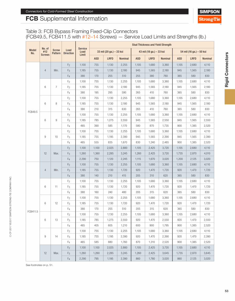
Table 3: FCB Bypass Framing Fixed-Clip Connectors (FCB49.5, FCB411.5 with #12–14 Screws) — Service Load Limits and Strengths (lb.)
Model No.
No. of #12
Screws
Screw Pattern
Load Direction
Service Load Limit
Stud Thickness and Yield Strength
33 mil (20 ga.) – 33 ksi 43 mil (18 ga.) – 33 ksi 54 mil (16 ga.) – 50 ksi
ASD LRFD Nominal ASD LRFD Nominal ASD LRFD Nominal
FCB49.5
4 Min.
F2 1,100 755 1,130 2,255 1,105 1,680 3,360 1,105 2,680 4,110
F3 1,185 755 1,130 2,180 945 1,565 2,180 945 1,565 2,180
F4 380 170 255 510 255 380 760 365 580 830
6 7
F2 1,100 755 1,130 2,255 1,105 1,680 3,360 1,105 2,680 4,110
F3 1,185 755 1,130 2,180 945 1,565 2,180 945 1,565 2,180
F4 380 195 295 590 265 410 760 365 580 830
6 8
F2 1,100 755 1,130 2,255 1,105 1,680 3,360 1,105 2,680 4,110
F3 1,185 755 1,130 2,180 945 1,565 2,180 945 1,565 2,180
F4 380 210 315 630 265 410 760 365 580 830
6 9
F2 1,100 755 1,130 2,255 1,105 1,680 3,360 1,105 2,680 4,110
F3 1,185 785 1,275 2,550 945 1,565 2,550 945 1,565 2,550
F4 465 390 585 1,170 580 870 1,735 900 1,385 2,520
9 10
F2 1,100 755 1,130 2,255 1,105 1,680 3,360 1,105 2,680 4,110
F3 1,185 755 1,195 2,390 945 1,565 2,390 945 1,565 2,390
F4 465 555 835 1,670 830 1,240 2,485 900 1,385 2,520
12 Max.
F2 1,100 1,100 2,025 2,880 1,105 2,425 3,720 1,105 2,680 4,110
F3 1,260 1,360 2,285 3,245 1,260 2,425 3,720 1,735 2,870 4,010
F4 2,290 750 1,120 2,245 1,115 1,670 3,020 1,200 2,125 3,020
FCB411.5
4 Min.
F2 1,100 755 1,130 2,255 1,105 1,680 3,360 1,105 2,680 4,110
F3 1,185 755 1,130 1,720 920 1,470 1,720 920 1,470 1,720
F4 380 140 210 415 205 310 620 365 580 830
6 11
F2 1,100 755 1,130 2,255 1,105 1,680 3,360 1,105 2,680 4,110
F3 1,185 755 1,130 1,720 920 1,470 1,720 920 1,470 1,720
F4 380 160 240 480 205 315 620 365 580 830
6 12
F2 1,100 755 1,130 2,255 1,105 1,680 3,360 1,105 2,680 4,110
F3 1,185 755 1,130 1,720 920 1,470 1,720 920 1,470 1,720
F4 380 170 255 510 205 315 620 365 580 830
6 13
F2 1,100 755 1,130 2,255 1,105 1,680 3,360 1,105 2,680 4,110
F3 1,185 785 1,275 2,550 920 1,470 2,550 920 1,470 2,550
F4 465 405 605 1,210 600 900 1,795 900 1,385 2,520
9 14
F2 1,100 755 1,130 2,255 1,105 1,680 3,360 1,105 2,680 4,110
F3 1,185 755 1,195 2,390 920 1,470 2,390 920 1,470 2,390
F4 465 585 880 1,760 870 1,310 2,520 900 1,385 2,520
12 Max.
F2 1,100 1,100 2,025 2,880 1,105 2,425 3,720 1,105 2,680 4,110
F3 1,260 1,260 2,285 3,245 1,260 2,425 3,645 1,735 2,870 3,645
F4 2,290 795 1,195 2,390 860 1,780 3,020 860 2,125 3,020
See footnotes on p. 51.
Rig
id C
onn
ecto
rs

C-C
F-20
17 ©
2017
SIM
PS
ON
STR
ON
G-T
IE C
OM
PAN
Y IN
C.
Connectors for Cold-Formed Steel Construction
54
FCB Supplemental Information
Table 4: FCB Bypass Framing Fixed-Clip Connectors (FCB43.5, FCB45.5, FCB47.5 with #10–16 Screws) — Service Load Limits and Strengths (lb.)
Model No.
No. of #10
Screws
Screw Pattern
Load Direction
Service Load Limit
Stud Thickness and Yield Strength
33 mil (20 ga.) – 33 ksi 43 mil (18 ga.) – 33 ksi 54 mil (16 ga.) – 50 ksi
ASD LRFD Nominal ASD LRFD Nominal ASD LRFD Nominal
FCB43.5
4 Min.
F2 — 490 735 815 490 735 815 490 735 815
F3 — 440 715 1,430 440 715 1,430 440 715 1,430
F4 465 340 515 1,025 530 795 1,585 900 1,385 2,520
6 Max.
F2 — 490 735 815 490 735 815 490 735 815
F3 — 660 1,075 2,145 660 1,075 2,145 660 1,075 2,145
F4 465 415 620 1,240 640 960 1,915 900 1,385 2,520
FCB45.5
4 Min.
F2 — 490 735 815 490 735 815 490 735 815
F3 — 660 990 1,980 670 1,085 2,170 670 1,085 2,170
F4 350 270 410 815 420 630 1,260 700 1,075 1,955
6 1
F2 — 490 735 815 490 735 815 490 735 815
F3 — 625 1,015 2,035 625 1,015 2,035 625 1,015 2,035
F4 350 350 525 1,055 545 815 1,630 700 1,075 1,955
6 2
F2 — 490 735 815 490 735 815 490 735 815
F3 — 670 1,085 2,170 670 1,085 2,170 670 1,085 2,170
F4 — 370 555 1,110 570 855 1,710 700 1,075 1,955
9 Max.
F2 — 490 735 815 490 735 815 490 735 815
F3 — 625 1,015 2,035 625 1,015 2,035 625 1,015 2,035
F4 350 460 690 1,380 700 1,065 1,955 700 1,075 1,955
FCB47.5
4 Min.
F2 — 490 735 815 490 735 815 490 735 815
F3 — 455 735 1,470 455 735 1,470 455 735 1,470
F4 175 195 290 580 300 450 895 380 585 1,060
6 3
F2 — 490 735 815 490 735 815 490 735 815
F3 — 425 690 1,380 425 690 1,380 425 690 1,380
F4 175 245 365 730 375 565 1,060 380 585 1,060
6 4
F2 — 490 735 815 490 735 815 490 735 815
F3 — 455 735 1,470 455 735 1,470 455 735 1,470
F4 175 260 390 775 380 585 1,060 380 585 1,060
6 5
F2 — 490 735 815 490 735 815 490 735 815
F3 — 785 1,275 2,550 785 1,275 2,550 785 1,275 2,550
F4 465 365 545 1,090 560 845 1,685 900 1,385 2,520
9 6
F2 — 490 735 815 490 735 815 490 735 815
F3 — 735 1,195 2,390 735 1,195 2,390 735 1,195 2,390
F4 465 500 750 1,505 775 1,165 2,325 900 1,385 2,520
12 Max.
F2 — 490 735 815 490 735 815 490 735 815
F3 — 735 1,195 2,390 735 1,195 2,390 735 1,195 2,390
F4 465 620 930 1,855 900 1,385 2,520 900 1,385 2,520
See footnotes on p. 51.
Rig
id C
onn
ecto
rs

C-C
F-20
17 ©
2017
SIM
PS
ON
STR
ON
G-T
IE C
OM
PAN
Y IN
C.
Connectors for Cold-Formed Steel Construction
55
FCB Supplemental Information
Table 5: FCB Bypass Framing Fixed-Clip Connectors (FCB49.5, FCB411.5 w/ #10–16 Screws) — Service Load Limits and Strengths (lb.)
ModelNo. of #10
Screws
Screw Pattern
Load Direction
Service Load Limit
Stud Thickness and Yield Strength
33 mil (20 ga.) – 33 ksi 43 mil (18 ga.) – 33 ksi 54 mil (16 ga.) – 50 ksi
ASD LRFD Nominal ASD LRFD Nominal ASD LRFD Nominal
FCB49.5
4 Min.
F2 — 490 735 815 490 735 815 490 735 815
F3 — 360 585 1,175 360 585 1,175 360 585 1,175
F4 115 150 225 450 230 345 690 265 410 745
6 7
F2 — 490 735 815 490 735 815 490 735 815
F3 — 340 550 1,100 340 550 1,100 340 550 1,100
F4 115 185 280 560 265 410 745 265 410 745
6 8
F2 — 490 735 815 490 735 815 490 735 815
F3 — 360 585 1,175 360 585 1,175 360 585 1,175
F4 115 200 295 595 265 410 745 265 410 745
6 9
F2 — 490 735 815 490 735 815 490 735 815
F3 — 785 1,275 2,550 785 1,275 2,550 785 1,275 2,550
F4 465 365 550 1,100 570 850 1,705 900 1,385 2,520
9 10
F2 — 490 735 815 490 735 815 490 735 815
F3 — 735 1,195 2,390 735 1,195 2,390 735 1,195 2,390
F4 465 525 790 1,575 810 1,220 2,435 900 1,385 2,520
12 Max.
F2 — 490 735 815 490 735 815 490 735 815
F3 — 735 1,195 2,390 735 1,195 2,390 735 1,195 2,390
F4 465 655 985 1,965 900 1,385 2,520 900 1,385 2,520
FCB411.5
4 Min.
F2 — 490 735 815 490 735 815 490 735 815
F3 — 210 320 375 210 320 375 210 320 375
F4 90 120 180 365 190 280 565 205 315 575
6 11
F2 — 490 735 815 490 735 815 490 735 815
F3 — 210 320 375 210 320 375 210 320 375
F4 90 150 225 450 205 315 575 205 315 575
6 12
F2 — 490 735 815 490 735 815 490 735 815
F3 — 210 320 375 210 320 375 210 320 375
F4 90 160 240 480 205 315 575 205 315 575
6 13
F2 — 490 735 815 490 735 815 490 735 815
F3 — 785 1,275 2,550 785 1,275 2,550 785 1,275 2,550
F4 465 380 570 1,140 585 880 1,760 900 1,385 2,520
9 14
F2 — 490 735 815 490 735 815 490 735 815
F3 — 735 1,195 2,390 735 1,195 2,390 735 1,195 2,390
F4 465 555 830 1,660 855 1,285 2,520 900 1,385 2,520
12 Max.
F2 — 490 735 815 490 735 815 490 735 815
F3 — 735 1,195 2,390 735 1,195 2,390 735 1,195 2,390
F4 465 695 1,045 2,090 900 1,385 2,520 900 1,385 2,520
See footnotes on p. 51.
Rig
id C
onn
ecto
rs

C-C
F-20
17 ©
2017
SIM
PS
ON
STR
ON
G-T
IE C
OM
PAN
Y IN
C.
Connectors for Cold-Formed Steel Construction
63
Supplemental Information for Slide-Clip and Rigid Connector
Does your project require DoD-compliant blast design?Although Allowable Strength Design (ASD) is widely used by Designers of Cold-Formed Steel (CFS) construction, some projects require additional connector limit states beyond the typical ASD values that are normally tabulated in our load tables. For example, many Department of Defense (DoD) projects require blast design of exterior wall framing and connections. Such projects may require the LRFD strength or nominal strength for the blast calculations. For a more comprehensive background on blast design please reference the Simpson Strong-Tie® Structural Engineering Blog at seblog.strongtie.com and enter the search term “DoD”.
Not finding what you need? Please contact Simpson Strong-Tie.
Table 1: SCB/MSCB Bypass Framing Slide-Clip Connector — Service Load Limits, LRFD Design Strengths and Nominal Strengths
Model No.
Dimensions (in.) No. of
#14 Shldr.
Screws
Load Dir.
Stud Thickness
33 mil (20 ga.) 43 mil (18 ga.) 54 mil (16 ga.) 68 mil (14 ga.)
L S
Service Load Limit (lb.)
LRFD Design
Strength (lb.)
Nominal Strength
(lb.)
Service Load Limit (lb.)
LRFD Design
Strength (lb.)
Nominal Strength
(lb.)
Service Load Limit (lb.)
LRFD Design
Strength (lb.)
Nominal Strength
(lb.)
Service Load Limit (lb.)
LRFD Design
Strength (lb.)
Nominal Strength
(lb.)
SCB43.5 3 1/2 1 1/2 2F2 860 830 1,180 975 975 1,475 990 1,215 1,795 990 1,215 1,795
F3 1,260 830 1,180 1,260 1,105 1,570 1,260 1,565 2,180 1,260 1,565 2,180
SCB45.5 5 1/2 2
2F2 860 785 1,115 975 975 1,475 990 1,215 1,795 990 1,215 1,795
F3 1,260 830 1,180 1,260 1,105 1,570 2,360 1,565 2,180 2,360 1,565 2,180
3F2 860 1,080 1,535 975 1,605 2,280 990 2,205 3,135 990 2,205 3,135
F3 1,260 1,080 1,535 1,260 1,605 2,280 1,260 2,025 2,825 1,260 2,025 2,825
MSCB45.5 5 1/2 2
2F2 860 785 1,115 990 1,245 1,770 1,055 1,855 2,640 1,195 1,920 2,730
F3 1,260 830 1,180 1,260 1,105 1,570 2,210 1,925 2,685 2,195 2,360 2,760
3F2 860 1,080 1,535 1,105 1,715 2,435 1,220 2,570 3,655 1,365 2,575 3,660
F3 1,260 1,080 1,535 1,260 1,605 2,280 2,910 3,090 3,610 2,910 3,090 3,610
SCB47.5 7 1/2 4
2F2 860 785 1,115 975 975 1,475 990 1,215 1,795 990 1,215 1,795
F3 1,260 830 1,180 1,260 1,105 1,570 2,260 1,515 2,115 2,260 1,515 2,115
3F2 860 1,080 1,535 975 1,605 2,280 990 2,205 3,135 990 2,205 3,135
F3 1,260 1,080 1,535 1,260 1,605 2,280 2,750 2,025 2,825 2,750 2,025 2,825
MSCB47.5 7 1/2 4
2F2 860 785 1,115 990 1,245 1,770 1,055 1,855 2,640 1,195 1,920 2,730
F3 1,260 830 1,180 1,260 1,105 1,570 2,210 1,925 2,685 2,195 2,360 2,760
3F2 860 1,080 1,535 1,105 1,715 2,435 1,220 2,570 3,655 1,365 2,575 3,660
F3 1,260 1,080 1,535 1,260 1,605 2,280 2,910 3,090 3,610 2,910 3,090 3,610
SCB49.5 9 1/2 6
2F2 860 785 1,115 975 1,105 1,570 990 1,215 1,795 990 1,215 1,795
F3 860 830 1,180 860 1,105 1,570 2,295 1,565 2,180 2,295 1,565 2,180
3F2 860 1,080 1,535 975 1,605 2,280 990 2,205 3,135 990 2,205 3,135
F3 860 1,080 1,535 1,260 1,605 2,280 2,620 2,025 2,710 2,620 2,025 2,710
SCB411.5 11 1/2 8
2F2 860 785 1,115 860 1,105 1,570 990 1,690 2,405 990 1,690 2,405
F3 860 830 1,180 860 1,105 1,570 1,890 1,470 1,720 1,890 1,470 1,720
3F2 860 1,080 1,535 860 1,605 2,280 990 2,205 3,135 990 2,205 3,135
F3 860 1,080 1,535 1,260 1,605 2,280 2,335 2,025 2,375 2,335 2,025 2,375
1. Tabulated values are for the connector and attachment to the stud-wall framing. The assembly strengths are the minimum of those listed and the anchorage values listed in Table 5 on p. 66.
2. Service Load Limit is the load at 1⁄8" deflection for use in evaluating the performance under service-level loads.3. LRFD Design Strength is the Nominal Strength multiplied by a resistance factor, φ.4. Nominal Strength is defined in AISI S100-07.
Rig
id C
onn
ecto
rs

C-C
F-20
17 ©
2017
SIM
PS
ON
STR
ON
G-T
IE C
OM
PAN
Y IN
C.
Connectors for Cold-Formed Steel Construction
64
Table 2: SCW Head-of-Wall Slide-Clip Connector — Service Load Limits, LRFD Design Strengths and Nominal Strengths
Model No. W (in.)
No. of #14
Shldr. Screws
Load Direction
Stud Thickness
33 mil (20 ga.) 43 mil (18 ga.) 54 mil (16 ga.)
Service Load Limit
(lb.)
LRFD Design Strength
(lb.)
Nominal Strength
(lb.)
Service Load Limit
(lb.)
LRFD Design Strength
(lb.)
Nominal Strength
(lb.)
Service Load Limit
(lb.)
LRFD Design Strength
(lb.)
Nominal Strength
(lb.)
SCW3.25 3 1/4 2 F4 935 730 865 1,030 1,010 1,175 1,095 1,200 1,680
SCW5.5 5 1/22 F4 1,125 730 1,020 1,655 1,010 1,580 1,950 1,590 2,220
3 F4 1,125 730 1,020 1,655 1,010 1,580 2,630 1,950 2,725
1. Tabulated values are for the connector and attachment to the stud-wall framing. The assembly strengths are the minimum of those listed and the anchorage values listed in Table 6 on p. 67.
2. Service Load Limit is the load at 1⁄8" deflection for use in evaluating the performance under service-level loads.3. LRFD Design Strength is the Nominal Strength multiplied by a resistance factor, φ.4. Nominal Strength is defined in AISI S100-07.
Supplemental Information for Slide-Clip and Rigid Connector
Table 3A: SSB Bypass Framing Slide-Clip Strut Connector — Service Load Limits, LRFD Design Strengths and Nominal Strengths
Model No.
No. of #14
Shldr. Screws
Load Direction
Stud Thickness
33 mil (20 ga.) 43 mil (18 ga.) 54 mil (16 ga.)
Service Load Limit
(lb.)
LRFD Design Strength
(lb.)
Nominal Strength
(lb.)
Service Load Limit
(lb.)
LRFD Design Strength
(lb.)
Nominal Strength
(lb.)
Service Load Limit
(lb.)
LRFD Design Strength
(lb.)
Nominal Strength
(lb.)
SSB3.518
2F2 1,085 830 1,185 1,220 1,105 1,570 1,830 1,715 2,440
F3 1,085 830 1,185 1,220 1,105 1,570 2,240 1,540 2,150
3F2 1,815 1,305 1,855 1,500 1,650 2,345 1,365 2,140 3,280
F3 1,815 1,305 1,855 2,650 1,730 2,415 2,915 1,960 3,050
See footnotes below.
Table 3B: FSB Bypass Framing Fixed-Clip Connector — Service Load Limits, LRFD Design Strengths and Nominal Strengths
Model No.
No. of #10–16 Screws
Load Direction
Stud Thickness
33 mil (20 ga.) 43 mil (18 ga.) 54 mil (16 ga.)
Service Load Limit
(lb.)
LRFD Design Strength
(lb.)
Nominal Strength
(lb.)
Service Load Limit
(lb.)
LRFD Design Strength
(lb.)
Nominal Strength
(lb.)
Service Load Limit
(lb.)
LRFD Design Strength
(lb.)
Nominal Strength
(lb.)
FSB3.518
4
F2 1,850 1,060 2,115 2,540 1,575 3,150 3,165 2,670 4,090
F3 2,045 1,060 2,115 2,855 1,575 3,150 3,405 2,585 3,965
F4 160 875 1,285 210 875 1,285 210 875 1,285
9
F2 2,815 2,385 4,770 3,900 3,550 7,095 4,170 4,090 6,075
F3 2,515 2,140 2,420 3,820 3,485 4,130 3,955 3,485 4,130
F4 160 875 1,285 210 875 1,285 260 875 1,285
1. Tabulated values are for the connector and attachment to the stud-wall framing. The assembly strengths are the minimum of those listed and the anchorage values listed in Table 5A and 5B on p. 66.
2. Service Load Limit is the load at 1⁄8" deflection for use in evaluating the performance under service-level loads.3. LRFD Design Strength is the Nominal Strength multiplied by a resistance factor, φ.4. Nominal Strength is defined in AISI S100-07.
Rig
id C
onn
ecto
rs

C-C
F-20
17 ©
2017
SIM
PS
ON
STR
ON
G-T
IE C
OM
PAN
Y IN
C.
Connectors for Cold-Formed Steel Construction
65
Supplemental Information for Slide-Clip and Rigid Connector
Table 4: FCB Bypass Framing Fixed-Clip Connector — Service Load Limits, LRFD Design Strengths and Nominal Strengths
Model No.
Dimensions (in.) Min.
or Max.
No. of #12–14
Self-Drilling Screws
Load Direction
Stud Thickness
33 mil (20 ga.) 43 mil (18 ga.) 54 mil (16 ga.)
L Smin SmaxService
Load Limit (lb.)
LRFD Design Strength
(lb.)
Nominal Strength
(lb.)
Service Load Limit
(lb.)
LRFD Design Strength
(lb.)
Nominal Strength
(lb.)
Service Load Limit
(lb.)
LRFD Design Strength
(lb.)
Nominal Strength
(lb.)
FCB43.5 3 1/2 1 1/2 1 1/2
Min. 4
F2 1,100 1,130 2,255 1,120 1,680 3,360 1,250 3,040 4,655
F3 1,185 1,130 2,180 1,185 1,565 2,180 1,185 1,565 2,180
F4 2,170 1,130 1,980 2,515 1,680 2,590 3,360 2,380 3,380
Max. 6
F2 1,100 1,690 3,245 1,120 2,425 3,720 1,250 3,040 4,655
F3 1,260 1,690 3,245 1,260 2,425 3,720 3,365 3,040 4,010
F4 2,415 1,690 2,635 2,860 2,330 3,315 2,865 3,055 4,345
FCB45.5 5 1/2 2 2
Min. 4
F2 1,100 1,130 2,255 1,120 1,680 3,360 1,105 2,680 4,110
F3 1,185 1,130 2,180 1,185 1,565 2,180 1,185 1,565 2,180
F4 1,225 1,130 1,720 1,500 1,515 2,150 2,100 2,120 3,015
Max. 9
F2 1,100 2,025 2,880 1,120 2,425 3,720 1,105 2,680 4,110
F3 1,260 2,285 3,245 1,260 2,425 3,720 3,365 2,870 4,010
F4 2,570 1,890 2,685 2,965 2,375 3,380 3,505 3,080 4,380
FCB47.5 7 1/2 4 1 1/2
Min. 4
F2 1,100 1,130 2,255 1,120 1,680 3,360 1,105 2,680 4,110
F3 1,185 1,130 2,115 1,185 1,515 2,115 1,185 1,515 2,115
F4 380 330 660 380 495 830 380 580 830
Max. 12
F2 1,100 2,025 2,880 1,120 2,425 3,720 1,105 2,680 4,110
F3 1,260 2,285 3,245 1,260 2,425 3,720 4,170 2,870 3,780
F4 1,875 1,060 2,120 1,875 1,575 3,155 1,875 2,3w10 3,440
FCB49.5 9 1/2 6 1 1/2
Min. 4
F2 1,100 1,130 2,255 1,120 1,680 3,360 1,105 2,680 4,110
F3 1,185 1,130 2,180 1,185 1,565 2,180 1,185 1,565 2,180
F4 380 255 510 380 380 760 380 580 830
Max. 12
F2 1,100 2,025 2,880 1,120 2,425 3,720 1,105 2,680 4,110
F3 1,260 2,285 3,245 1,260 2,425 3,720 4,345 2,870 4,010
F4 2,290 1,120 2,245 2,290 1,670 3,020 2,290 2,125 3,020
FCB411.5 11 1/2 8 1 1/2
Min. 4
F2 1,100 1,130 2,255 1,120 1,680 3,360 1,105 2,680 4,110
F3 1,185 1,130 1,720 1,185 1,470 1,720 1,185 1,470 1,720
F4 380 210 415 380 310 620 380 580 830
Max. 12
F2 1,100 2,025 2,880 1,120 2,425 3,720 1,105 2,680 4,110
F3 1,260 2,285 3,245 1,260 2,425 3,645 4,015 2,870 3,645
F4 2,290 1,195 2,390 2,290 1,780 3,020 2,290 2,125 3,020
1. Tabulated values are for the connector and attachment to the stud-wall framing. The assembly strengths are the minimum of those listed and the anchorage values listed in Table 5 and 6 on pp. 66, 67.
2. Service Load Limit is the load at 1⁄8" deflection for use in evaluating the performance under service-level loads.3. LRFD Design Strength is the Nominal Strength multiplied by a resistance factor, φ.4. Nominal Strength is defined in AISI S100-07.
Rig
id C
onn
ecto
rs

C-C
F-20
17 ©
2017
SIM
PS
ON
STR
ON
G-T
IE C
OM
PAN
Y IN
C.
Connectors for Cold-Formed Steel Construction
66
Supplemental Information for Slide-Clip and Rigid Connector
Table 5A: Anchor Values (lb.) in the F2 and F3 Direction for SCB, FCB, MSCB and SSB
Anchorage TypeMinimum
Base Material
No. of Anchors
SCB and FCB MSCB SSB
LRFD Design Strength
Nominal Strength
LRFD Design Strength
Nominal Strength
LRFD Design Strength
Nominal Strength
#12 self-drilling screws Simpson Strong-Tie® X Metal screws
XQ1S1214, X1S1214
A36 steel 3/16" thick
2 1,270 2,010 1,635 2,505 1,875 3,280
3 1,790 2,745 2,440 3,740 2,140 3,280
4 2,540 4,015 3,265 5,005 — —
Simpson Strong-Tie #12–24 x 1¼" Strong-Drive® XL Large-Head Metal screws
XLQ114T1224, XLQ114B1224-2K
A36 steel 3/16" thick
2 1,780 2,730 2,175 3,330 — —
3 2,630 4,035 3,260 5,000 — —
4 3,565 5,465 4,345 6,660 — —
Simpson Strong-Tie 0.157" x 5/8" power-actuated fasteners
PDPAT-62KP
A36 steel 3/16" thick
2 700 1,130 830 1,710 1,980 3,435
3 935 1,550 1,250 2,430 2,240 3,435
4 1,430 2,175 1,665 3,415 — —
Simpson Strong-Tie 0.157" x 5/8" power-actuated fasteners
PDPAT-62KP
A572 or A992 steel 3/16" thick
2 935 1,435 975 1,710 — —
3 1,275 2,000 1,465 2,430 — —
4 1,875 2,870 1,950 3,415 — —
Simpson Strong-Tie ¼" x 1¾" Titen® Hex-Head Masonry screws
TTN25134H
Concrete f'c = 2,500 psi
2 605 1,515 605 1,515 — —
3 710 1,775 710 1,775 — —
4 815 2,035 815 2,035 — —
Welded E70XX electrodes
A36 steel 3/16" thick
Hard side: 2"Free side: 1"
2,780 4,265 3,265 5,005 3,320 5,085
See footnotes below.
Table 5B: Anchor Values (lb.) in F1, F2, F3, and F4 Direction for FSB
Anchorage Type No. of Anchors
FSB
F1 F2 / F3 F4
LRFD Design Strength
Nominal Strength
LRFD Design Strength
Nominal Strength
LRFD Design Strength
Nominal Strength
#12–14 self-drilling screws2 435 495 1,875 3,200 875 1,285
4 435 495 3,745 6,075 875 1,285
Simpson Strong-Tie 0.157" x 5/8" power-actuated fasteners
PDPAT-62KP
2 — — 1,310 2,530 — —
4 435 495 2,620 6,075 875 1,285
WeldedHard side: 2"Free side: 1"
435 495 5,330 6,020 875 1,285
1. Tabulated values are for the anchorage only. The assembly strengths are the minimum of those listed above and the connector capacity and attachment to the stud-wall framing listed in Tables 1–4 on pp. 63–65.
2. LRFD Design Strength is the Nominal Strength multiplied by a resistance factor, φ.3. Nominal Strength is defined in AISI S100-07.4. For the Service Load Limit, use the values listed for the connectors in Tables 1–4 on pp. 63–65.
Rig
id C
onn
ecto
rs

C-C
F-20
17 ©
2017
SIM
PS
ON
STR
ON
G-T
IE C
OM
PAN
Y IN
C.
Connectors for Cold-Formed Steel Construction
67
Supplemental Information for Slide-Clip and Rigid Connector
Table 6: Anchor Values (lb.) in the F4 Direction
Anchorage Type No. of Anchors Load
Type
FCB43.5 FCB45.5 FCB47.5 FCB49.5 FCB411.5
SCW3.25 SCW5.5Min./Max.
Min./Max. Min. Max. Min. Max. Min. Max.
#12–24 self-drilling
screws
2
LRFD Design Strength
1,000 655 410 710 295 425 190 305 1,020 1,875
Nominal Strength 1,530 1,005 625 1,090 455 650 295 465 1,565 2,945
3
LRFD Design Strength
1,105 720 450 785 320 470 215 335 1,330 —
Nominal Strength 1,690 1,105 685 1,200 490 725 330 515 2,040 —
4
LRFD Design Strength
2,010 1,310 785 1,425 570 855 440 610 — 2,295
Nominal Strength 3,075 2,010 915 2,180 665 1,310 515 930 — 3,805
Simpson Strong-Tie®
0.157" PDPAT powder-actuated
fasteners
2
LRFD Design Strength
655 425 265 465 190 280 120 200 830 1,470
Nominal Strength 1,005 650 405 710 295 430 185 305 1,270 2,255
3
LRFD Design Strength
745 490 305 530 215 310 135 225 895 —
Nominal Strength 1,140 745 465 810 330 480 210 345 1,370 —
4
LRFD Design Strength
1,345 880 545 950 390 570 230 410 — 2,385
Nominal Strength 2,060 1,350 835 1,460 600 870 355 625 — 3,660
Simpson Strong-Tie ¼" x 1¾"
Titen® hex-head screws
2
LRFD Design Strength
580 380 230 415 170 245 300 175 — —
Nominal Strength 1,660 1,080 660 1,180 480 700 400 500 — —
3
LRFD Design Strength
660 435 265 470 195 280 140 205 — —
Nominal Strength 1,880 1,240 700 1,340 515 800 400 580 — —
4
LRFD Design Strength
905 590 365 635 265 385 390 275 — —
Nominal Strength 2,580 1,680 915 1,820 670 1,100 525 780 — —
WeldedHard side: 2"Free side: 1"
LRFD Design Strength
5,070 3,320 1,265 3,210 910 1,920 720 1,375 — —
Nominal Strength 7,765 5,085 1,475 3,750 1,065 2,245 1,280 1,610 — —
1. Tabulated values are for the anchorage only. The assembly strengths are the minimum of those listed above and the connector capacity and attachment to the stud-wall framing listed in Tables 1–4 on pp. 63–65.
2. LRFD Design Strength is the Nominal Strength multiplied by a resistance factor, φ.3. Nominal Strength is defined in AISI S100-07.4. For the Service Load Limit, use the values listed for the connectors in Tables 1–4 on pp. 63–65.
Rig
id C
onn
ecto
rs