Embed Size (px)
Citation preview

GE Oil & Gas
GE Data Classification : Public
Consolidated* AP1000 3707S Edition of Nuclear 3700 Series Safety ValveMaintenance Manual

2 | GE Oil & Gas © 2017 General Electric Company. All rights reserved.
NOTICE!
For valve configurations not listed in this manual, please contact your local Green Tag* Center for assistance.
Conversion TableAll the USCS values are converted to
metric values using the following conversion factors:
USCS Unit Conversion Factor Metric Unit
in. 25.4 mm
lb. 0.4535924 kg
in2 6.4516 cm2
ft3/min 0.02831685 m3/min
gal/min 3.785412 L/min
lb/hr 0.4535924 kg/hr
psig 0.06894757 barg
ft lb 1.3558181 Nm
°F 5/9 (°F-32) °C

Consolidated AP1000 3707S Edition Safety Valve Maintenance Manual | 3© 2017 General Electric Company. All rights reserved.
Table of ContentsTable of Contents ..................................................................................................................................................................................3
I. Product Safety Sign and Label System .................................................................................................................5
II. Safety Alerts ......................................................................................................................................................................6
III. Introduction .......................................................................................................................................................................7
IV. Design Features and Considerations ....................................................................................................................8
1. Materials ........................................................................................................................................................................8
2. Design Life .....................................................................................................................................................................8
3. Thermal Compensation ..........................................................................................................................................8
4. Thermodisc ...................................................................................................................................................................8
5. Blowdown ......................................................................................................................................................................8
6. Operating Gap .............................................................................................................................................................8
V. Nomenclature ..................................................................................................................................................................8
VI. Terminology for Safety Valves ............................................................................................................................... 12
VII. 3700 Series Safety Valve Principles and Relationship to Plant Conditions ....................................... 13
VIII. Recommended Installation Practice .................................................................................................................. 15
IX. Handling, Storage and Pre-installation ............................................................................................................. 20
X. Pre-maintenance and Post-maintenance Testing ....................................................................................... 21
A. System Hydrostatic Testing ............................................................................................................................... 21
B. Set Pressure and Function ability Testing ................................................................................................... 22
XI. Valve Removal ............................................................................................................................................................... 24
XII. Removal and Reassembly of the AP1000 3707S Series Valve Bonnet Assembly with Jacking Device without affecting the set pressure ........................................................................... 25
A. Removal Instructions ............................................................................................................................................ 25
B. Reassembly Instructions ..................................................................................................................................... 25
XIII. Disassembly and Inspection................................................................................................................................... 26
XIV. Maintenance .................................................................................................................................................................. 29
A. Lapping Procedure ................................................................................................................................................ 29
B. Spindle Runout ......................................................................................................................................................... 38
C. Disc Replacement and Disc-Spindle Bearing Requirements ............................................................. 38
D. Lapping Compression Screw or Adaptor .................................................................................................... 39
E. Lapping Lower Spring Washer ......................................................................................................................... 39
XV. Repair ................................................................................................................................................................................ 41
A. Re-machining Nozzle Seats ............................................................................................................................... 41
B. VTL Set-up .................................................................................................................................................................. 41

4 | GE Oil & Gas © 2017 General Electric Company. All rights reserved.
Table of Contents C. Nozzle Removal ................................................................................................................................................................... 41
D. Lathe Set-Up for Machining of Nozzle when Removed from Base ............................................................. 41
E. Machining of Nozzle Seat ................................................................................................................................................ 41
F. Nozzle Installation ............................................................................................................................................................... 42
G. Yoke Rod Replacement .................................................................................................................................................... 42
H. Extended Wear Modification ........................................................................................................................................ 42
XVI. Reassembly ................................................................................................................................................................................ 43
XVII. Field Settings .............................................................................................................................................................................. 48
XVIII. Sealing Valves after Test ...................................................................................................................................................... 48
XIX. Gagging Procedure ................................................................................................................................................................. 48
XX. Setting the valve set pressure using the AP1000 3707S Hydraulic Set Device .......................................... 49
XXI. Using the AP1000 3707S Hydraulic Set Device as an auxiliary lift device to check the set pressure of the valve during service or with bench testing ......................................................................... 51
XXII. Troubleshooting ....................................................................................................................................................................... 53
XXIII. Maintenance Tools and Supplies ..................................................................................................................................... 54
XXIV. Replacement Parts .................................................................................................................................................................. 54
Manufacturer’s Field Service and Repair Program ........................................................................................................................ 55

Consolidated AP1000 3707S Edition Safety Valve Maintenance Manual | 5© 2017 General Electric Company. All rights reserved.
DANGER — Immediate hazards that WILL result in severe personal injury or death.
WARNING — Hazards or unsafe practices that COULD result in severe personal injury or death.
CAUTION — Hazards or unsafe practices that COULD result in minor personal injury.
ATTENTION — Hazards or unsafe practices that COULD result in product or property damage
If and when required, appropriate safety labels have been included in the rectangular margin blocks throughout this manual. Safety labels are vertically oriented rectangles as shown in the representative examples (left and below), consisting of three panels encircled by a narrow boarder. The panels can contain four messages that communicate:
• The level of hazard seriousness.
• The nature of the hazard.
• The consequence of human, or product, interaction with the hazard.
• The instructions, if necessary, on how to avoid the hazard.
The top panel of the format contains a single word (DANGER, WARNING,
CAUTION or ATTENTION) that communicates the level of hazard seriousness.
The center panel contains a pictorial that communicates the nature of the hazard, and the possible consequence of human or product interaction with the hazard. In some instances of human hazards the pictorial may depict what preventive measures to take, such as wearing protective equipment.
The bottom panel may contain an instruction message on how to avoid the hazard. In the case of human hazard, this message may also contain a more precise definition of the hazard, and the consequences of human interaction with the hazard, than can be communicated solely by the pictorial.
I. Product Safety Sign and Label System
Do not remove bolts if pressure in line, as this will result in severe personal
injury or death.
Know all valve exhaust/leakage points to avoid
possible severe personal injury or death.
Wear necessary protective equipment to prevent
possible injury
Do not drop or strike.
1
2
3
4
1 2 3 4

6 | GE Oil & Gas © 2017 General Electric Company. All rights reserved.
Danger AlertsA DANGER alert describes actions that may cause severe personal injury or death. In addition, it may provide preventive measures to avoid severe personal injury or death.
DANGER alerts are not all-inclusive. GE cannot know all conceivable service methods nor evaluate all potential hazards. Dangers include:
• High temperature/pressure can cause injury. Ensure all system pressure is absent before repairing or removing valves.
• Do not stand in front of a valve outlet when discharging. STAND CLEAR OF VALVE to avoid exposure to trapped, corrosive media.
• Exercise extreme caution when inspecting a pressure relief valve for leakage.
• Allow the system to cool to room temperature before cleaning, servicing, or repairing. Hot components or fluids can cause severe personal injury or death.
• Always read and comply with safety labels on all containers. Do not remove or deface container labels. Improper handling or misuse could result in severe personal injury or death.
• Never use pressurized fluids/gas/air to clean clothing or body parts. Never use body parts to check for leaks, flow rates, or areas. Pressurized fluids/gas/air injected into or near the body can cause severe personal injury or death.
• It is the owner’s responsibility to specify and provide protective wear to protect persons from pressurized or heated parts. Contact with pressurized or heated parts can result in severe personal injury or death.
II. Safety Alerts Read – Understand – Practice
• Do not work or allow anyone under the influence of intoxicants or narcotics to work on or around pressurized systems. Workers under the influence of intoxicants or narcotics are a hazard to themselves and other employees. Actions taken by an intoxicated employee can result in severe personal injury or death to themselves or others.
• Always perform correct service and repair. Incorrect service and repair can result in product or property damage or severe personal injury or death.
• Always use the correct tool for a job. The misuse of a tool or the use of an improper tool can result in personal injury, damage to product or property.
• Ensure the proper “health physics” procedures are followed, if applicable, before starting operation in a radioactive environment.
Caution AlertsA CAUTION alert describes actions that may result in a personal injury. In addition, they may describe preventive measures that must be taken to avoid personal injury. Cautions include:
• Heed all service manual warnings. Read installation instructions before installing valve(s).
• Wear hearing protection when testing or operating valves.
• Wear appropriate eye and clothing protection.
• Wear protective breathing apparatus to protect against toxic media.

Consolidated AP1000 3707S Edition Safety Valve Maintenance Manual | 7© 2017 General Electric Company. All rights reserved.
GE’s 3700 Series Safety Valves are spring-loaded safety valves for steam service. The 3700 Series Safety Valves are provided in accordance with the requirements of the ASME Code III, Division 1, Class 1 and 2, for materials, design, fabrication, examinations, pressure testing and overpressure protection. In addition these valves are provided in accordance with the Owner's Design Specification.
Every effort has been made to provide a design which can be readily serviced in the field and which has a high degree of reliability to meet the stringent needs of our Nuclear Power customers.
3700 Series Safety Valves are capacity certified, including demonstration of function under Section III of the ASME Code for application in Nuclear Power Systems and ASME PTC 25 (Power Test Code).
Safety valves are carefully tested, set and adjusted on saturated steam to verify set pressure, popping action, and seat tightness in accordance with the ASME Code Section III and ASME Code OM, Appendix I.
Inlet and outlet connections of each valve are protected for shipment and storage. These flange protectors must remain intact to prevent sand or dirt from accumulating in either inlet or outlet connections. Accumulations of sand, dirt, etc. in safety valve inlet ports will be carried across the seat while the valve is in operation and is frequently the case of seat leaks and unsatisfactory operation. Upon removal of flange protectors, check for any material inside the valve inlet nozzle or body bowl.
Safety valves must be connected on full sized vessel nozzles as shown in Figure 1. No stop valve can be placed between the pressure vessel and the safety valve as specified by ASME Code regulations. The valve should be installed in a vertical position only. Inlet bolts must be drawn down evenly to protect distortion of the valve body and inlet nozzle. Refer to Table 1A (pg 20) and the GA drawing for proper torquing values at inlet and outlet flanges.
The size of the discharge piping as shown in Figure 1 should never be less than the valve outlet size. The arrangement should be as short and direct as possible, and should be designed and installed to eliminate all possible piping strains on the valve.
Installation of safety valves and the design of inlet and outlet piping should comply with the requirements of the applicable ASME Code Section II.
Figure 1: Typical Valve Installation
III. Introduction

8 | GE Oil & Gas © 2017 General Electric Company. All rights reserved.
1. MaterialsMaterials of construction are mandated by the ASME Code Section III and ASME Code Section II, Part D, and the Owner's Design Specification. Actual materials of construction are specific on the applicable as-built construction drawing.
2. Design LifeFor most service conditions, pressure retaining parts and parts subject to mechanical stresses, such as valve necks, yoke rods, etc. are designed for a design life equivalent to the reactor unit life.
3. Thermal CompensationThe yoke rod design, together with proper selection of yoke rod and spindle materials, renders the valve relatively free from changes in pressure settings due to inlet temperature variations. High ambient temperatures adjacent to the valve spring and yoke rods may cause set pressure variations and need to be considered when adjusting the valve. Temperature stabilization is always necessary prior to adjusting a valve for set pressure.
4. ThermodiscThe Thermodisc design in providing for the rapid equalization of temperature around the valve seat, provides a high degree of tightness. Selection of materials
provide “Thermal Flexibility” and “Mechanical Flexibility.” Thermodisc are now giving excellent results at 5500 psi (374 bar) and 1150°F (621°C).
5. Blowdown3700 Series Safety Valves are capable of 5% blowdown. Blowdown requirements are dependent on the applicable edition and addenda of ASME Code Section III and the Owner's Design Specification. If blowdown testing is not mandatory, then the adjusting rings are set by the proration method for 3-9% blowdown. Because of the limited capacity of the in-house test system, if blowdown testing is mandatory, testing is performed out-of-house at a suitable test facility. Blowdown testing is required when 5% blowdown is mandatory or when blowdown testing is required by the applicable ASME Code Section III.
6. Operating GapConsolidated Safety Valves are tested and proven tight for operation gaps of 6%, operating gap being defined as the difference between operating pressure and the set pressure of the low set safety valve. Although tightness is a function of design, it should be realized that with smaller operating gaps it is necessary to increase maintenance. Increases in incidents of seat leakage, simmer, etc., can be expected because of less allowance for system pressure transients and other variables.
IV. Design Features and Considerations
V. NomenclatureFigure 2A (pg 9) shows a typical 3700 Series Safety Valve, designs RT21 through RT24. Figure 2B (pg 10) shows a typical RT25 design. Figure 2C (pg 11) shows a typical AP1000 RT25 design.
The compression screw-to-top spring washer interface in the 3700 Series safety valves may come with a thrust bearing or a thrust washer. See Figures 19 through 24 (pg 40).
This manual should be used in conjunction with the applicable as-built construction drawing. Nomenclature may vary between this manual and the construction drawing depending on the generation of the drawing.
Refer to the as-built construction for mounting dimensions, materials of construction and optional features such as:
• Extended wear parts
• Double outlets
• Block bodies
• Butt welding ends
• Manual lifting levers
• Auxiliary devices
• Bottom guided nozzles
CAUTION: Manual lifting levers are not required by the ASME Code Section III for safety valves and are not recommended to be installed during plant operation.

Consolidated AP1000 3707S Edition Safety Valve Maintenance Manual | 9© 2017 General Electric Company. All rights reserved.
Ref. No. Qty. Nomenclature
1 Base Assembly
1A 1 Base
1B 1 Nozzle
1C 10 Base Stud
1D 10 Base Stud Nut
2 1 Yoke
3 2 Yoke Rod
3A 1 Cover
4 4 Yoke Rod Nut
5 1 Disc
6 Spring Assembly
6A 1 Top Spring Washer
6B 1 Bottom Spring Washer
6C 1 Spring
7 1 Compression Screw
7A 1 Compression Screw Locknut
8 1 Spindle
8A 1 Lift Stop (not in all designs)
8B 1 Lift Stop Cotter Pin
9 1 Upper Adj. Ring
10 1 Lower Adj. Ring
11 1 Upper Ring Pin
11A 1 Lower Ring Pin
12 1 Disc Holder
13 1 Disc Collar
13A 1 Disc Collar Cotter Pin
14 1 Guide
15 1 Cap
15A 1 Cap Locking Screw
16 1 Release Nut
16A 1 Release Nut Cotter Pin
17 1 Top Lever
17A 1 Top Lever Pin
18 1 Drop Lever
18A 1 Drop Lever Pin
19 2 Lever Cotter Pin
Figure 2A: Basic Safety Valve: RT21 through RT24
V. Nomenclature (Contd.)
Figure 2A Note: For dimensions refer to the as-built construction drawing.

10 | GE Oil & Gas © 2017 General Electric Company. All rights reserved.
Figure 2B: Basic Safety Valve: RT25
V. Nomenclature (Contd.)
Figure 2B NOTE: For dimensions refer to the as-built
construction drawing.
Ref. No. Qty. Nomenclature
1 Base Assembly
1A 1 Outlet Flange
1B 1 Weld Rod
1C 16 Nozzle
1D 16 Base Stud
1E 16 Pin
2 1 Yoke
3 2 Yoke Rod
4 4 Yoke Rod Nut
5 1 Disc
6 Spring Assembly
6A 1 Top Spring Washer
6B 1 Bottom Spring Washer
6C 1 Spring
8 1 Compression Screw
10 1 Spindle
10A 1 Hardface
20 1 Lower Ring Pin
21 1 Upper Ring Pin
22 1 Lower Adj. Ring
23 1 Upper Adj. Ring
24 1 Lift Stop
25 1 Disc Collar
26 1 Disc Holder
27 1 Guide
28 1 Yoke Rod Support
29 1 Drop Lever
30 1 Drop Lever Pin
31 1 Top Lever
32 1 Release Nut
33 1 Cap
34 1 Top Lever Pin
35 1 Locknut
36 16 Stud Nuts
37 1 Cotter Pin Rel. Nut
38 2 Service Port Plugs
39 1 Set Screw
40 1 Cotter Pin Rel. Nut
40A 1 Cotter Pin Disc. Col
41 2 Lever Cotter Pins
53 1 Warning Tag

Consolidated AP1000 3707S Edition Safety Valve Maintenance Manual | 11© 2017 General Electric Company. All rights reserved.
V. Nomenclature (Contd.)
Ref. No. Qty. Nomenclature
1 1 Base Inlet Facing
1A 1 Base1B 1 Nozzle3 1 Bonnet
4 1 Spindle
5 1 Disc
6 1 Disc Collar7 1 Disc Holder8 1 Lower Adjusting Ring
9 1 Upper Adjusting Ring10 1 Spring and Washers Assembly
10A 1 Spring
10B 1 Bottom Spring Washer10C 1 Top Spring Washer
11 1 Compression Screw12 4 Cap Screw13 1 Plunger
14 1 Bolted Cap15 1 Disc Guide16 1 Compression Screw Locknut17 10 Stud
18 2 Stud19 14 Nut20 1 Cover Plate
21 1 Limit Switch Assembly22 1 Bracket Kit23 1 Upper Adjusting Ringpin24 1 LOwer Adjusting Ringpin
25 1 Drain Plug26 1 Lift Stop27 2 Cotter Pin
28 12 Inlet Stud
29 12 Inlet Stud Nut30 32 Outlet Stud
31 32 Outlet Stud Nut32 1 Gag Plug
33 1 Gag Bolt34 1 Nameplate Section III
35 1 Tag Plate
36 1 Seal Wire37 1 Seal
38 4 Nameplate/Tag Plate Screw
39 1 Inlet Gasket40 2 Outlet Gasket
41 1 Tag Plate
NOTE: For dimensions refer to the as-built construction drawing.
Figure 2C: AP1000 3707S Safety Valve
Figure 2C

12 | GE Oil & Gas © 2017 General Electric Company. All rights reserved.
1. Back Pressure
Back pressure is the static pressure existing at the outlet of a safety device due to pressure in the discharge system.
2. Blowdown
Blowdown is the difference between actual popping pressure of a safety valve and actual reseating pressure expressed as a percentage of set pressure or in pressure units.
3. Bore Area
Bore area is the minimum cross-sectional area of the nozzle.
4. Bore Diameter
Bore diameter is the minimum diameter of the nozzle.
5. Chatter
Chatter is abnormal rapid reciprocating motion of the moveable parts of a safety valve in which the disc contacts the seat.
6. Closing Pressure
Closing pressure is the value of decreasing inlet static pressure at which the valve disc reestablishes contact with the seat or at which lift becomes zero.
7. Disc
A disc is the pressure containing moveable element of a pressure safety valve which effects closure.
8. Inlet Size
Inlet size is the nominal pipe size of the inlet of a pressure relief valve, unless otherwise designated.
9. Lift
Lift is the actual travel of the disc away from closed position when a valve is relieving.
10. Lifting Device
A lifting device is a device for manually opening a safety device by the application of external force to lessen the spring loading which holds the valve closed.
11. Nozzle
A nozzle is the pressure containing element which constitutes the inlet flow passage and includes the fixed portion of the seat closure.
12. Outlet Size
Outlet size is the nominal pipe size of the outlet of a safety valve, unless otherwise designated.
13. Overpressure
Overpressure is a pressure increase over the set pressure of a safety valve, usually expressed as a percentage of set pressure.
14. Popping Pressure
Popping pressure is the value of increasing inlet static pressure at which the disc moves in the opening direction of a faster rate as compared with corresponding movement at higher or lower pressures. It applies only to safety or safety relief valves on compressible fluid service.
15. Pressure Containing Member
A pressure containing member of a safety valve is a part which is in actual contact with the pressure media in the protected vessel.
16. Pressure Retaining Member
A pressure retaining member of a safety valve is a part which is stressed due to its function in holding one or more pressure containing members in position.
17. Rated Lift
Rated lift is the design lift at which a valve attains its rated relieving capacity.
18. Safety Valve
A safety valve is a pressure relief valve actuated by inlet static pressure and characterized by rapid opening or pop action.
19. Set Pressure
Set pressure is the value of increasing inlet static pressure at which a safety valve displays the operational characteristics as defined under “Popping Pressure.” It is one value of pressure stamped on the safety valve.
20. Seat
A seat is the pressure containing contact between the fixed and moving portions of the pressure containing elements of a valve.
VI. Terminology for Safety Valves(Terminology unique to safety devices are published in Section 2 of ASME: PTC25 and ANSI B95.1)

Consolidated AP1000 3707S Edition Safety Valve Maintenance Manual | 13© 2017 General Electric Company. All rights reserved.
21. Seat Tightness Pressure
Seat tightness pressure is the specified inlet static pressure at which a quantitative seat leakage test is performed in accordance with a standard procedure.
22. Seat Diameter
Seat diameter is the smallest diameter of contact between the fixed and moving portions of the pressure containing elements of a valve.
23. Simmer
Simmer is the audible or visible escape of fluid between the seat and disc at an inlet static pressure below the popping pressure and at no measurable capacity. It applies to safety or safety valves on compressible fluid service.
24. Warn
See “Simmer.”
VI. Terminology for Safety Valves (Contd.)
VII. Safety Valve Operating Principles and Relationship to Plant ConditionsTo properly understand how different conditions affect valve operation, it is important to understand the basics of valve design. Refer to terminology for safety valves, Section IV for more specific definition of terms relative to the valve under discussion throughout this manual.
The particular features that affect valve performance can generally be described as:
1. popping pressure
2. lift
3. overpressure
4. closing pressure
5. seat tightness pressure
Referring to Figure 3 (pg 15), the popping pressure is that pressure where the valve disc begins to lift when system pressure has increased to the point where the force generated by the system pressure times the disc seat area will equal the spring load. The spring force is adjustable by turning of the compression screw.
Lift is the amount of disc travel upward along the valve center-line during valve opening or closing. Beyond a point known as “Full Rated Lift,” capacity is a function of overpressure since the nozzle orifice is controlling the flow.
Overpressure is a value of pressure increase above the valve popping pressure. The overpressure at which the valve is flowing is designated as accumulation. The valve must be at full rated lift at 3% accumulation so that the nozzle will control the flow. For overpressure greater than 3%, capacity increases linearly. For overpressure less than 3%, nothing specifically can be stated except that the valve is probably not in full rated lift . Experience has shown that the 3700 Series when opening on steam will reach approximately 70% of full rated lift at 0% overpressure.
Closing pressure is that pressure at which the valve will reseat. This is generally specified as minimum reseat
pressure or as percent blowdown as expressed by the following equation:
Popping pressure minus closing pressurePercent blowdown = ___________________ X 100 Popping pressure
In all valves used for compressible fluid services, the valves are equipped with adjusting rings. Adjusting rings are mechanical devices incorporated in the valve to change the distribution of forces on the disc and disc holder controlling the valve lift and the valve closing pressure. Adjusting ring positions should be located as specified in this maintenance manual unless proper full capacity testing can justify different ring positions.
The valve “seat tightness pressure” is that pressure at which the steam will be prevented from seeping through the nozzle and disc seat interface. If seats are properly conditioned, the valve can be shown to be tight to 94% of its set pressure. The thermodisc design, low spindle bearing point plus a top guided nozzle, all combine with other special features to provide the most perfect vertical alignment of internal valve components possible. Valve tightness is also a function of bearing stress between seats. This bearing stress decreases with increasing inlet pressure, therefore, increasing the possibility of seat leakage. The proper alignment of components in a vertical plane has a major impact on tightness. A change in the valve spring load caused by outside influences will also cause leakage at pressures lower than the seat tightness pressure established when the outside influences are not present.
Factors which contribute to causing leakage can be categorized as follows:
a. Large piping loads on the valve outlet – body deformations which cause misalignment of components may cause valve seating forces to be reduced.
14 | GE Oil & Gas © 2017 General Electric Company. All rights reserved.
b. Vibrations – movements and acceleration forces in the horizontal and vertical planes may cause spring forces in the vertical plane to be reduced.
c. Inlet Temperature – valve testing without the proper stable inlet temperature does not allow thermal expansions in the valve to stabilize and define the seat area. Additionally, a reduction in spring force due to material relaxation or insufficient thermal growth of components in the axial plane along the valve inlet centerline may also cause reduced seating forces.
d. Ambient Temperatures – the same effect as noted in “Inlet Temperature” will result if proper reactor ambient conditions are not simulated.
e. A combination of any of the above may contribute to a drop in valve pop or seating tightness pressure.
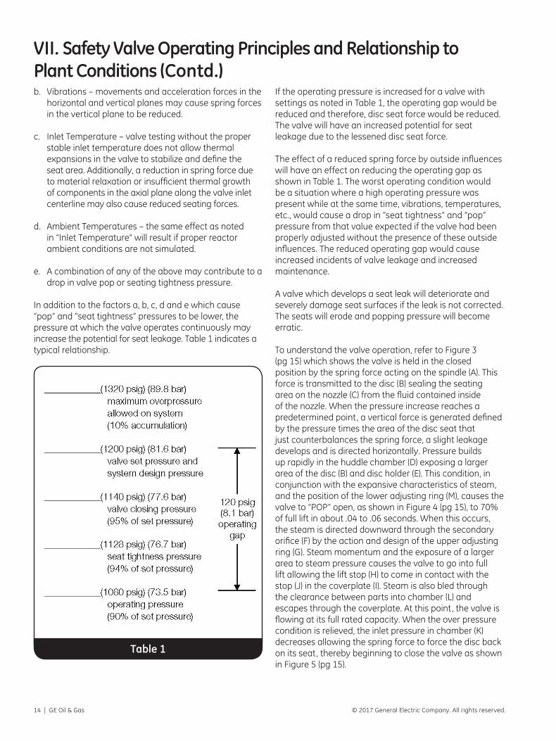
In addition to the factors a, b, c, d and e which cause “pop” and “seat tightness” pressures to be lower, the pressure at which the valve operates continuously may increase the potential for seat leakage. Table 1 indicates a typical relationship.
Table 1
If the operating pressure is increased for a valve with settings as noted in Table 1, the operating gap would be reduced and therefore, disc seat force would be reduced. The valve will have an increased potential for seat leakage due to the lessened disc seat force.
The effect of a reduced spring force by outside influences will have an effect on reducing the operating gap as shown in Table 1. The worst operating condition would be a situation where a high operating pressure was present while at the same time, vibrations, temperatures, etc., would cause a drop in “seat tightness” and “pop” pressure from that value expected if the valve had been properly adjusted without the presence of these outside influences. The reduced operating gap would cause increased incidents of valve leakage and increased maintenance.
A valve which develops a seat leak will deteriorate and severely damage seat surfaces if the leak is not corrected. The seats will erode and popping pressure will become erratic.
To understand the valve operation, refer to Figure 3 (pg 15) which shows the valve is held in the closed position by the spring force acting on the spindle (A). This force is transmitted to the disc (B) sealing the seating area on the nozzle (C) from the fluid contained inside of the nozzle. When the pressure increase reaches a predetermined point, a vertical force is generated defined by the pressure times the area of the disc seat that just counterbalances the spring force, a slight leakage develops and is directed horizontally. Pressure builds up rapidly in the huddle chamber (D) exposing a larger area of the disc (B) and disc holder (E). This condition, in conjunction with the expansive characteristics of steam, and the position of the lower adjusting ring (M), causes the valve to “POP” open, as shown in Figure 4 (pg 15), to 70% of full lift in about .04 to .06 seconds. When this occurs, the steam is directed downward through the secondary orifice (F) by the action and design of the upper adjusting ring (G). Steam momentum and the exposure of a larger area to steam pressure causes the valve to go into full lift allowing the lift stop (H) to come in contact with the stop (J) in the coverplate (I). Steam is also bled through the clearance between parts into chamber (L) and escapes through the coverplate. At this point, the valve is flowing at its full rated capacity. When the over pressure condition is relieved, the inlet pressure in chamber (K) decreases allowing the spring force to force the disc back on its seat, thereby beginning to close the valve as shown in Figure 5 (pg 15).
VII. Safety Valve Operating Principles and Relationship toPlant Conditions (Contd.)

Consolidated AP1000 3707S Edition Safety Valve Maintenance Manual | 15© 2017 General Electric Company. All rights reserved.
The lower adjusting ring (M) is an adjustable device that also cushions the disc when the valve closes. Improper adjustment can cause the disc to seat with such force that the disc is damaged thereby causing the valve to leak. The lower ring also eliminates simmer at the valve popping pressure and allows for adjustment in obtaining a clean popping and lifting valve.
VIII. Recommended Installation Practice1. Safety valves need not be installed directly on
components within the system which they serve to protect. Pressure relief valves should be installed at a location in the system as close as practicable to the major source of service pressure loading anticipated to arise within the pressure containing boundary of the system.
NOTE: The design of the mating inlet and outlet piping and the installation requirements of applicable ASME Code Section III are mandatory.
VII. Safety Valve Operating Principles and Relationshipto Plant Conditions (Contd.)
Figure 3: Valve Closed
Figure 4: Valve in Full Lift
Figure 5: Valve Closing

16 | GE Oil & Gas © 2017 General Electric Company. All rights reserved.
2. The safety valve shall be connected to the header independent of any other connection, and attached as close as possible to the header, without any intervening pipe or fitting.
3. No valve of any description should be placed between the required pressure relief valve and the header, nor on the discharge pipe between the pressure relief valve and the atmosphere.
4. In no case may the inlet piping to the valve have a bore less than the nominal size of the valve inlet.
NOTE: It may be possible that the special designs dictate a different requirement. This should be cleared with GE Engineering prior to valve installation. In a similar manner, outlet pipe size should not be restricted to a size less than the nominal valve outlet size.
5. Excessive pressure loss at the inlet of the safety valve will cause extremely rapid opening and closing of the valve, which is known as “chattering.” Chattering may result in lowered capacity as well as damage to the seating surface of the valve. Severe chattering can also cause damage to other parts of the valve.
The following recommendations will assist in eliminating the factors that produce chatter:
a. The diameter of the header nozzle should be at least equivalent to the diameter of the inlet size of the valve. For example, a six inch (152.4 mm) valve should be mounted on a header nozzle which has a minimum bore of six inches (152.4 mm). The header nozzle should be as short as possible.
b. Header nozzle corners must be rounded to a radius of not less than ¼ of the opening diameter.
c. Pressure drop due to friction flow to the inlet of the valve should not be greater than 50% of the expected blowdown of the safety valve.
d. To decrease the effects of a phenomena known as “sonic vibrations,” the following recommendations are made:
(1) Safety valves should be installed at least eight to ten pipe diameters downstream from any bend in a steam line. This distance should be increased if the direction of the change of the steam flow is from vertical upwards to horizontal in such a manner as to increase density of the flow in the area directly beneath the safety valve nozzles.
(2) Safety valves should not be installed closer than eight to ten pipe diameters either upstream or downstream from diverging or converging “Y” fittings.
(3) In cases where piping configuration renders the above two recommendations impractical or impossible, the downstream corners of the header nozzle inlets should be rounded to a greater extent than the upstream corners. The header nozzle entrance should be rounded so the radius at the downstream corner will be equal to a minimum of ¼ of the nozzle diameter. The radius should be reduced gradually, leaving only a small portion of the upstream corner with a smaller radius.
(4) Safety valve nozzles should never be installed in a steam line in a position directly opposite a branch line of equivalent size on the lower side of the steam line.
6. Excessive steam line vibrations are known to produce shifts in pressure relief valve set pressures. Results of sizeable vibrations may possibly introduce chatter with ultimate damage to the valve in addition to reduced capacity. This vibration also contributes to increased incidents of seat leakage. Considerations should be given to eliminating this problem prior to installing the valves on the unit.
7. Steam flowing vertically out a discharge elbow produces a downward reaction on the elbow. Bending stresses in the valve are determined by the amount of this reactive force and the moment arm between the point of steam exhaust and the section being analyzed for bending stresses. The effects of reaction force, vibration, and seismic loads on all valve components and discharge piping should be considered when designing the valve system.
VIII. Recommended Installation Practice (Contd.)

Consolidated AP1000 3707S Edition Safety Valve Maintenance Manual | 17© 2017 General Electric Company. All rights reserved.
8. For optimum performance, safety valves must be serviced regularly and maintained. So that servicing can be properly performed, valves should be located for easy access. Sufficient working space should be provided around the valve to permit access to adjusting rings. If two or more valves are located close together, the outlets should be paralleled to offer as much protection as possible to personnel repairing or working close to the safety valve.
9. Because foreign material passing into and through a safety valve is damaging, the system on which the valve is tested and finally installed must also be inspected and cleaned. New systems are prone to contain welding beads, pipe scale, and other foreign material which are inadvertently trapped during construction and destroy the valve seating surfaces the first few times the valve opens. The system should be purged thoroughly before the safety valve is installed.
10. For weld-end inlet valves, completely assembled valves may be installed without necessity for disassembly at the time of welding. During welding, the valve neck should be insulated to reduce thermal stresses. When stress relieving, insulation should also be utilized to reduce thermal stresses. In service, the valve neck should be insulated at least to the inlet neck valve body bowl juncture.
11. Safety valves should be installed in a vertical position. Nominal tolerance on vertical installation is ±1°.
12. The area of the outlet piping from a pressure relief valve should be not less than the area of the outlet connection. Where more than one pressure relief valve is connected to a common outlet pipe, the area of the pipe should not be less than the aggregate area of the outlet connections to the safety valves.
13. All safety valve discharges should be piped so that the effluent is discharged clear from running boards or platforms. Ample provision for gravity drain shall be made in the discharge pipe at or near each pressure relief valve where water or condensation may collect. Each valve has an open gravity drain through the body below the level of the valve seat and this drain should be piped to a safe discharge area.
14. If a silencer is used on a safety valve, it should have sufficient outlet area to prevent back pressure from interfering with the proper operation and discharge capacity of the valve. The silencer or other devices should be so constructed as to avoid a possibility of restriction of the steam passages due to corrosion deposits.
15. Exhausts, drains and vents must be installed so that they will not impose undue stresses on the safety valve. These stresses can produce body distortion and leakage. The following recommendations are provided:
a. Discharge piping should not be supported by the valve. The maximum weight on the outlet of the valve should not exceed the weight of a short radius elbow and flange plus a twelve (12) inch (304.8 mm) straight length of standard weight thickness pipe.
b. Clearance between the valve exhaust piping and the discharge stack should be sufficient to prevent contact when considering thermal expansion of the header, valve, and discharge stack. Movements due to vibration, temperature changes, and valve reaction forces should also be considered to ensure adequate exhaust piping to discharge stack clearance.
c. Flexible metal hoses are not generally recommended, but if used to connect valve outlets to discharge stacks, must have sufficient length and be designed and installed in such a manner that they will not become “solid” in any position. Better results are obtained if the hoses are installed so that they will permit movement by bending, rather than stretching and compressing along their length.
16. In no case should discharge piping be of smaller size than the valve outlet. The length of the discharge stack will govern its size and with increased lengths, stack diameters may have to be increased. When several valves exhaust into a common header, the header should be designed to accommodate the capacity of all the valves relieving simultaneously.
17. When lifting the valve, the valve should always remain in a vertical position. The valve may be lifted by using a sling around the valve yoke and the valve outlet neck. In no case should the valve be lifted by the lifting lever.
VIII. Recommended Installation Practice (Contd.)

18 | GE Oil & Gas © 2017 General Electric Company. All rights reserved.
18. At the time of installation, all covers on the valve inlet and outlet should be removed. The internals of the valve are to be checked for cleanliness. No foreign matter is permitted at the valve inlet or outlet since it may possibly damage the valve components or be dropped into the header.
All face surfaces which will seal pressure with gaskets shall be inspected for cleanliness or any defects that can cause leakage. Burrs, mashed serrations, uneven surfaces, etc., are all possible leakage producing items. Proper gasket sizes and pressure ratings should be checked prior to starting valve installation.
19. It is of utmost importance that the gasketing used be dimensionally correct for the specific flange and that it fully clears the valve inlet and outlet openings. Gasket, flange facings, and bolting should meet the service requirements for the pressure and temperature involved. Other considerations for installing the valve include:
a. When installing flanged valves, the flange bolts must be pulled down evenly to prevent body distortion and consequent misalignment and leakage.
b. Install the inlet gasket, if applicable, on the header mounting flange. Check for cleanliness, etc. When possible, inlet studs on the mounting flange should be used to guide the valve onto the header mounting flange. Inlet studs should be lubricated with an acceptable (approved for nuclear) lubricant.
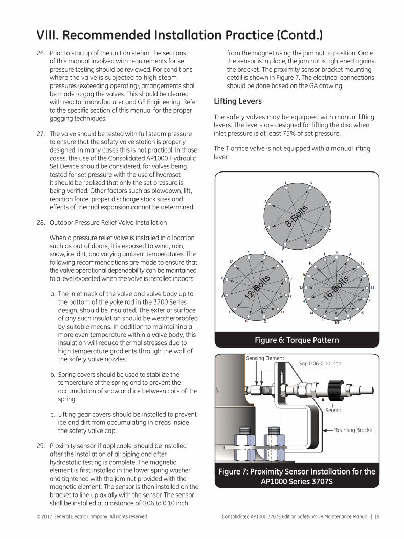
c. When in position, install the stud nuts until the nuts are finger tight. Referring to Figure 6, an initial value of torque is to be placed on each
stud in the sequence specified. The second sequence of increasing torque is to be applied in the same bolting sequence. This process is to be continued until the final torque load, as specified in the GA drawing, is applied. Upon completion, recheck each stud torque.
As an extra precaution, the gap between the two mating flanges should be checked during the torquing process to ensure that the flanges are being pulled together evenly. Calipers may be used for this verification. A final inspection and review should be made to verify that all of the requirements for bolting the valve inlets have been implemented.
d. In a like manner, the outlet piping may now be installed. A complete inspection of components and their cleanliness is to be made prior to further work. Studs are to be lubricated with the approved lubricant.
e. Install the outlet gasket and studs with nuts. Stud nuts are to be pulled down finger tight. Referring to Table 2 (pg 20) and the GA drawing, an initial value of torque is to be applied. The procedures outlined in step (c) are to be followed.
20. After assurances that the valve is properly installed, the drainage piping from the valve body bowl is to be connected. This line must also be flexible so it will not create loads on the valve at operating conditions.
21. Prior to completion of the installation, a visual check should be made to ensure that the valve lifting lever, if applicable, is free to operate.
22. At the time of installation, an inspection of the valve should be made to confirm that all adjustments are properly locked and sealed as required by ASME Code Section III.
23. Flanged valves should be installed without insulation.
24. When hydrostatic testing (1.5 x design) is required on the valve inlet, the valve is to be removed and a blank flange used in place of the valve.
25. For operational hydrostatic tests at the valve inlet which do not exceed valve set pressure (1.0 x design) the valves may be gagged. Refer to specific sections of this manual for proper techniques. Ensure that the gag is removed upon completion of the inlet hydro.
Note: The AP1000 3707S series valves is designed to be gag tested at 1.25 x design pressure (1500-1550 psig)
VIII. Recommended Installation Practice (Contd.)
Know all valve exhaust/leakage points to avoid
possible severe personal injury or death.
Consolidated AP1000 3707S Edition Safety Valve Maintenance Manual | 19© 2017 General Electric Company. All rights reserved.
26. Prior to startup of the unit on steam, the sections of this manual involved with requirements for set pressure testing should be reviewed. For conditions where the valve is subjected to high steam pressures (exceeding operating), arrangements shall be made to gag the valves. This should be cleared with reactor manufacturer and GE Engineering. Refer to the specific section of this manual for the proper gagging techniques.
27. The valve should be tested with full steam pressure to ensure that the safety valve station is properly designed. In many cases this is not practical. In those cases, the use of the Consolidated AP1000 Hydraulic Set Device should be considered, for valves being tested for set pressure with the use of hydroset, it should be realized that only the set pressure is being verified. Other factors such as blowdown, lift, reaction force, proper discharge stack sizes and effects of thermal expansion cannot be determined.
28. Outdoor Pressure Relief Valve Installation
When a pressure relief valve is installed in a location such as out of doors, it is exposed to wind, rain, snow, ice, dirt, and varying ambient temperatures. The following recommendations are made to ensure that the valve operational dependability can be maintained to a level expected when the valve is installed indoors:
a. The inlet neck of the valve and valve body up to the bottom of the yoke rod in the 3700 Series design, should be insulated. The exterior surface of any such insulation should be weatherproofed by suitable means. In addition to maintaining a more even temperature within a valve body, this insulation will reduce thermal stresses due to high temperature gradients through the wall of the safety valve nozzles.
b. Spring covers should be used to stabilize the temperature of the spring and to prevent the accumulation of snow and ice between coils of the spring.
c. Lifting gear covers should be installed to prevent ice and dirt from accumulating in areas inside the safety valve cap.
29. Proximity sensor, if applicable, should be installed after the installation of all piping and after hydrostatic testing is complete. The magnetic element is first installed in the lower spring washer and tightened with the jam nut provided with the magnetic element. The sensor is then installed on the bracket to line up axially with the sensor. The sensor shall be installed at a distance of 0.06 to 0.10 inch
VIII. Recommended Installation Practice (Contd.)from the magnet using the jam nut to position. Once the sensor is in place, the jam nut is tightened against the bracket. The proximity sensor bracket mounting detail is shown in Figure 7. The electrical connections should be done based on the GA drawing.
Lifting Levers
The safety valves may be equipped with manual lifting levers. The levers are designed for lifting the disc when inlet pressure is at least 75% of set pressure.
The T orifice valve is not equipped with a manual lifting lever.
Figure 6: Torque Pattern
Figure 7: Proximity Sensor Installation for the AP1000 Series 3707S
Sensing Element Gap 0.06-0.10 inch
Sensor
Mounting Bracket

20 | GE Oil & Gas © 2017 General Electric Company. All rights reserved.
VIII. Recommended Installation Practice (Contd.)
Table 2: Suggested Minimum Torque Values for Inlet and Outlet Flanged Joints
Nominal Pipe Size
ANSI B16.5
Flange Class
Stud Size Torque ft/lb
3 150 5/8 60
6 150 3/4 100
8 150 3/4 100
10 150 7/8 160
6 300 3/4 100
8 300 7/8 160
10 300 1 245
2.5 1500 1 245
3 1500 1-1/8 355
4 1500 1-1/4 500
6 1500 1-3/8 680
8 1500 1-5/8 1100
IX. Handling, Storage and Pre-Installation1. The safety valve, either crated or uncrated, should
always be kept with the inlet flange down, i.e., never laid on its side, to prevent possible misalignment and damage to internals.
2. Safety valves should be stored in a dry environment to protect them from the weather. They should not be removed from the skids or crates until immediately prior to installation.
3. Flange protectors and sealing plugs should not be removed until the valve is ready to be bolted into the installation, i.e., both inlet and outlet.
4. Safety valves, either crated or uncrated, should never be subjected to sharp impact. This would be most likely to occur by bumping or dropping during loading or unloading from a truck or while moving with a power conveyor, such as fork lift truck. While hoisting to the installation, care should be exercised to prevent bumping the valve against steel structures and other objects.
5. Uncrated safety valves should be moved or hoisted by wrapping a chain or sling around discharge neck, then around the valve yoke in such manner to ensure the valve is in vertical position during lift , i.e., not lifted in horizontal position. Never lift the valve by the lifting
lever. Crated valves should always be lifted with the inlet flange down, i.e., same as installation position. Lifting instructions for the 3707T and the 3707S series safety valves are given in Section IX.10 and IX1.11 respectively.
6. When safety valves are uncrated and the flange protectors removed immediately prior to installation, meticulous care should be exercised to prevent dirt and other foreign materials from entering the inlet and outlet ports while bolting in place.
7. “Short-Term Storage” is defined as storage not exceeding six months from date of shipment. “Long-Term Storage” is defined as storage not exceeding one year from date of shipment. “Extended Storage” is defined as storage exceeding one year from date of shipment.
a. For “Short-Term Storage,” the storage requirements are the same as those specified for long term storage.
b. For “Long-Term Storage,” items shall be stored indoors or equivalent with all provisions and requirements as set forth in extended storage items except that heat and temperature control is not required. Level C storage requirements as specified
Notes:1. Caution: torque values are suggested minimum. Maximum torque
is the responsibility of the user.2. The bolt stress is approximately 30,000 psi when the torque load is
applied.3. Values are based on clean, lubricated threads and bearing surfaces. 4. Values are based on ASME SA193 Grade B7 bolting, coarse series
threads.5. Caution: bolting shall comply with the requirements of ANSI B16.5
and the applicable ASME Code Section III.6. Calibrated torque wrenches shall be used. 7. Spiral wound stainless steel gaskets with filler is recommended. Filler
shall be suitable for steam service. 8. Caution: flanged joints should be designed with facings to
control gasket compression within the gasket manufacturers’ recommendations.
9. Lubricant is the responsibility of the user. No specific lubricant is recommended.
10. For the AP1000 3707S Series Safety Valve, see the GA drawing for minimum torque requirements, gasket type and size, and lubricant requirements.

Consolidated AP1000 3707S Edition Safety Valve Maintenance Manual | 21© 2017 General Electric Company. All rights reserved.
IX. Handling, Storage and Pre-Installation (Contd.)9. For any reason, should it be necessary to store the
valve in an uncrated condition, the valve shall be stored in an upright position on the inlet flange, making certain the inlet flange is protected from damage. Never lay the valve on its side as damage to the internals and misalignment may be incurred. The valve when removed from the shipping container, to prevent entrance of foreign material, shall have the protectors left intact. Use every precaution to prevent the entrance of dirt and foreign material into the valve.
10. For the 3707T safety valve, lift the valve using eye bolt, 3/4" (196 mm) minimum size, installed in outlet flange bolt holes and with non-wire rope (cloth preferred), slings or chokers around the yoke. Rig for a three-point lift. A chain fall or a come-a-long will permit lifting the valve in a vertical upright position and provide for ease of balancing. The crated weight of the “T” orifice valve is approximately 3200 pounds (1451 kg). The net weight is approximately 3000 pounds (1360 kg). Although smaller orifice valves weigh slightly less, handling gear should be sized for the larger valve. Refer to the construction drawing for the center of gravity location.
11. For the AP1000 3707S Series Safety Valve, lift the valve using three (3x) eye bolts, 1.00-8 UNC size, installed in the bonnet. Rig for a three-point lift. The crated weight of the AP1000 3707S Series Safety Valve is approximately 3300 lbs (1497 kg) and valve weight is 2750 lbs (1250 kg). Handling gear should be rated for 3300 lbs. Refer to the construction drawing for the center of gravity location.
in NQA-1, Part II, Subpart 2.2, shall apply.
c. For “Extended Storage,” items shall be stored within a fire resistant, tear resistant, weather tight, and well ventilated building or equivalent enclosure. Precautions shall be taken against vandalism. This area shall be situated and constructed so that it will not be subjected to flooding; the floor shall be paved or equal, and well drained. Items shall be placed on pallets or shoring to permit air circulation. The area shall be provided with uniform heating and temperature control or its equivalent to prevent condensation and corrosion. Minimum temperature shall be 40°F (4.5°C) and maximum temperature shall not exceed 140°F (60°C). Valves or parts shall be stored in the original shipping container. The shipping container shall be kept in an upright position as indicated by the markings on the crate. DO NOT STACK. Level B storage requirements as specified in NQA-1, Part II, Subpart 2.2, shall apply. All material, upon receipt, should be inspected and all coatings and packaging damage during shipping and handling shall be put into condition before storing.
8. The Nuclear Power Plant owner or his agent is responsible for providing a program to protect the cleanliness level of the valves and their spare parts at the construction site in compliance with ANSI NQA-1, Part II, Subpart 2.1, Cleanliness Level B.
X. Pre-Maintenance and Post-Maintenance TestingThe various phases of testing to which the valve will be subjected in its lifetime consists of the following:
1. System Hydrostatic Testinga. 1½ times designb. Operational
2. Set Pressure & Functionability Testinga. Bench testingb. In place testing on header.
In all cases, Quality Assurance requirements should be established prior the start of testing.
A. System Hydrostatic Testing
1. For those conditions where the safety valve is installed and the system hydrostatic test pressure
exceeds the set pressure of the valve, the valve is to be removed and the piping connection blanked. Although the valve is designed and tested to industry standards acceptable to the nuclear industry, that testing was previously conducted on component parts or a partially assembled valve. In those cases where the valve cannot be removed, a hydrostatic test plug must be installed.
2. For those conditions where an operational hydrostatic test is implemented on the main steam line and the inlet pressure does not exceed the valve set pressures, the valves shall be gagged. The AP1000 3707S Series Safety Valves are designed for hydrostatic testing at 1.25 x design pressure (1500 -1550 psig maximum) with the gagging device. Refer to applicable sections of this maintenance manual for gagging techniques. It is

22 | GE Oil & Gas © 2017 General Electric Company. All rights reserved.
X. Pre-Maintenance and Post-Maintenance Testing (Contd.)possible for steam valves to open on cold fluid at pressures less than the nameplate pressure and therefore, also leak at pressures less than that experienced on steam. The valve gag will apply sufficient force to the disc to maintain tightnes.
B. Set Pressure and Functionability Testing
The design and functionability of the valve is proven by years of field experience, prototype testing and maintenance history. During assembly the valve components are visually inspected and if recommended maintenance techniques are followed, a functional valve will develop. Since the basic design principle of a valve is to keep all forces acting in a vertical straight line path, any potential problems resulting from errors in assembly of the valve will be immediately apparent by an erratic valve set pressure or valve leakage. Therefore, in addition to determining the proper opening valve pressure, any set pressure testing will also verify proper valve assembly.
All functional testing should be performed in accordance with ASME Code OM, Appendix I, and this manual.
1. Bench Testing
Steam valves must be tested on steam. These valves relieve large quantities of steam, therefore, it is impractical to bench test the valves at full steam pressure, temperature and capacity. Since many other factors such as downtime, decontamination, etc. affect availability of steam systems, the one practical solution to retesting of valves on steam is by the use of a small bench test facility. Bench testing, with approved and calibrated hydraulic assist equipment is an acceptable method to determine the popping point of the valve. The Consolidated AP1000 3707S Hydraulic Set device is the only hydraulic assist device approved for use by GE on the AP1000 3707S Series Safety Valve. If a bench test facility has sufficient steam pressure and substantial capacity, then the assist device may not be required, but the use of a lift restrictor, Figure 8 (pg 23) or equivalent, is mandatory to prevent damage to valve seats. For the AP1000 3707S Series Safety Valve, the gag plug may be used as lift restrictor. The lift restrictor should be adjusted after the valve has become thermally stable and immediately before the test is conducted. Considerations should be given to the actual ambient temperature and environment to which the valve will be subjected since this will affect overall valve performance.
Bench testing ensures that the valve is capable of being set pressure adjusted and is leak tight.
Nuclear power plants perform testing in accordance with ASME Code OM, Appendix I. During plant scheduled shutdowns, set pressure and seat tightness are verified on certain valves. Safety valves that fail to meet the acceptance criteria are usually sent off-site for “as-receive” testing, refurbishment, and “as-left” testing. During plant startup, set pressure and seat tightness may be re-verified.
A typical test procedure guideline is given below. The test facility shown in Figure 9 (pg 24) is only representative, and the schematic is not intended to define all requirements for an adequate test facility.
a. Upon proper reconditioning and reassembly of a valve in accordance with the applicable section of the maintenance manual, the valve should then be properly mounted for bench testing as shown in Figure 9 (pg 24).
When preparing to test a valve and valve set pressure is not accurately known, precautions should be taken to ensure that no danger exists to personnel or equipment should the
valve lift at a pressure less than required by the
nameplate. If a double outlet design is applicable,
one outlet should be blanked during testing.

Consolidated AP1000 3707S Edition Safety Valve Maintenance Manual | 23© 2017 General Electric Company. All rights reserved.
X. Pre-Maintenance and Post-Maintenance Testing (Contd.)b. After installation on the test facility, open the
by-pass valving slowly to equalize the pressure between the accumulator and the safety valve. Inlet pressure should be not more than 80% of expected set pressure. Open the gate valve fully and allow a minimum of 30 minutes heat up time before attempting to adjust the set pressure of the valve. Heat up the safety valve until the valve is thermally stabilized as determined by checking the valve body temperature with a contact pyrometer.
c. After “heat up time” the valve shall be set to pop at the required pressure using The AP1000 3707S Hydraulic Set Device or full inlet steam pressure with a lift restrictor. If a lift restrictor is used, it should be adjusted for lift restriction after the valve is heated and thermally stable.
d. After the set up pressure has been attained, pop the valve three additional times with a waiting period of ten minutes between pops. Record each pop. Pops should not trend in one direction. At least one pop should turn around. Trending in one direction may indicate the valve is not thermally stable.
e. A check of the safety valve seat for leakage should be performed by pressurizing the accumulator to a pressure equal to the system operation pressure or the specified leak test pressure, whichever is applicable. If the facility has insufficient pressure to accomplish this requirement, it is permissible to utilize existing accumulator steam pressure and the AP1000 3707S Hydraulic Set Device to assist in obtaining the desired leak test pressure.
After allowing sufficient time for the condensate to evaporate (30 minutes minimum) the
seat shall be checked for leakage by placing a polished stainless steel rod, whose temperature is not to exceed 100°F, (38°C), 2” to 3” (50.8 to 76.7 mm) away from the seat. If detectable beads of moisture are formed on the rod, the valve should be considered as leaking and should be reconditioned prior to installation on the unit.
f. Upon satisfactory completion of testing, which ensures compliance with ASME Code requirements, complete valve assembly and then seal all external adjustments.
Figure 8: Restrictor Arrangement
Do not stand near the valve outlet to
prevent injury should the valve accidentally open. If a double outlet design is applicable, one outlet
should be blanked.

24 | GE Oil & Gas © 2017 General Electric Company. All rights reserved.
X. Premaintenance and Post-Maintenance Testing (Contd.)2. In Place Testing on the Main Steam Header
To verify the set pressure on the installation, the valve should be installed in its normal operation condition. It is preferable that the system be over pressured and the valve blown so that the valve adjustments and station design adequacy can be verified. If this is not possible, then the set pressure only can be adjusted using the Consolidated AP1000 3707S Hydraulic Set Device. The AP1000 3707S Series valves require the use of the Hydraulic Set Device. The adjusting rings should be set at the positions outlined in this manual. To ensure accuracy, all pressure gauges should be accurately calibrated along with the hydroset device. At the time that final adjustments are made to the valve, the inlet temperature and ambient temperature should be typical of that expected in service. The valve should be monitored to ensure that it is thermally stable prior to final adjustment. A seat tightness check should be conducted at the conclusion of the set pressure testing. Upon completion of testing, which ensures compliance with ASME Code requirements, complete valve assembly and then seal all external adjustments.
Figure 9: Bench Test Schematic
XI. Valve RemovalAlthough proper maintenance can be performed with the valve in place, system cleanliness requirements generally dictates that the valve should be removed. If applicable, refer to “Safety Notice” and “Safety Precautions,” then proceed as outlined in this section.
1. Remove pressure from the pressure relief valve before loosening any bolting. To make certain that no pressure remains under the valve disc, the system dump valve (or similar device) should be actuated.
2. Remove the discharge piping attached to the outlet flange of the valve. Discard outlet gasket.
3. Remove any other connections to the valve, such as drain piping, insulation, etc.
4. Attach appropriate lifting gear to the valve as outlined in other parts of this manual. Never lift the valve by the lifting lever. See Section VII, Step 10, of this manual.
5. Remove inlet bolting, then increase the load on the lifting gear until the valve is clear of the mating flange. Use care to prevent bumping the valve against any superstructure or dropping the valve. Remove and discard inlet gasket.
6. After removal, clean the valve exterior as required. Refer to Section X of this manual for further disassembly.
The lifting lever is not designed to lift the disc when the pressure
is less than 75% of the valve set pressure. Failure to relieve the
pressure under the disc could cause injury to
personnel.

Consolidated AP1000 3707S Edition Safety Valve Maintenance Manual | 25© 2017 General Electric Company. All rights reserved.
Figure 10: Disassembly by jacking of the bonnet assembly
XII. Removal and Reassembly of the AP1000 3707S Series Valve Bonnet Assembly with Jacking Device without af-fecting the set pressureNOTE: This procedure details the removal of the bonnet assembly without affecting the spring load.
NOTE: The bonnet cap seals will need to be broken that compromises the factory set of the valve.
A. Removal Instructions
1. Remove the four (4x) Bonnet Cap Screws from the bonnet
2. Remove the Bonnet Cap to expose the top of the spindle and the compression screw.
3. Screw a 1-3/4-8 UN-2B Heavy Hex Nut to the threads of the spindle till it makes contact with the compression screw.
4. If the threads on the spindle are not long enough to thread the heavy hex nut till it makes contact with the compression screw, a spacer may be used between the top of the compression screw and the heavy hex nut.
5. Using a wrench with sufficient leverage or a wrench with torque multiplier, apply enough force to tighten the 1-3/4- 8 UN heavy hex nut to 1/8 turn.
6. This causes the disc to lift off the nozzle seat and the loads acting on the bonnet mounting bolting is now transferred to the 1-3/4-8 UN heavy hex nut.
7. Loosen and remove the limit switch mounting bracket nuts. After disconnecting the limit switch wiring, remove the limit switch/bracket assembly and place it in a safe location.
8. Use 3 1-1/2 inch eyebolts on the bonnet holes to lift the bonnet assembly vertically up. Care should be taken not to cock the assembly to bind the disc holder and the guide.
NOTE: The bonnet assembly will have the seating surface of the disc exposed at the bottom. Care should be taken not to damage the disc seating surface while material handling of the bonnet assembly.
9. Place the bonnet assembly on a wooden skid such that the disc seating area is not resting on any surfaces that may damage the seat area.. It is recommended to prepare the skid to receive the
bonnet flange. The skid should have an opening in the center that is large enough and deep enough to receive the disc holder and disc.
10. Now the disc and nozzle seating surfaces are accessible to perform preventive maintenance. If the nozzle sealing surface needs to be reconditioned, remove the adjusting ring pin and record the position of the lower adjusting relative to the nozzle seat per instructions in Section XIII-15 and Figure 16 (pg 28). Lower the adjusting ring below the seat surface before reconditioning the seat. Other critical surfaces are also accessible for inspection.
B. Reassembly Instructions
11. After repair and reconditioning, lower the bonnet assembly vertically into the valve body bowl.
12. Screw the bonnet nuts and torque to the appropriate torque requirements identified in the GA drawing.
13. Install the limit switch – bracket assembly at the appropriate location per the installation instruction from Section VIII.
14. With the bonnet assembly assembled securely, loosen the 1-3/4- 8 UN heavy hex nut to relieve the tension in the spindle and rest the disc back on the nozzle.
1-3/4 Jack Nut
Spacer
Seat access for lapping

26 | GE Oil & Gas © 2017 General Electric Company. All rights reserved.
Parts from one valve should not be
interchanged with parts from another valve.
1. Remove the four (4x) Bonnet Cap Screws from the bonnet.
2. Remove the Bonnet Cap to expose the top of the spindle and the compression screw.
3. Remove the top lever cotter pin, top lever pin and top lever. Discard the cotter pin.
4. Loosen cap set screw and lift off cap and drop lever assembly.
5. Remove the release nut cotter pin and release nut. Discard the cotter pin. Measure the height of the spindle protruding outside the compression screw (dimension A) and record that dimension so that the approximate valve set pressure can be reestablished later in the event the compression screw is removed. Refer to Figure 11 (pg 27).
For valves with extended wear parts, Figure 31 (pg 43), the TeflonTM bushing must first be removed. A 5/32" Allen wrench is required. Remove the cap screws and lock washers that lock the retainer to the head of the compression screw. Remove the split bushing from the head of the compression screw.
6. Removal of the valve yoke differs with the type of valve design.
For AP1000 3707S design, the following steps should be followed:
(1) Remove the proximity switch wiring and remove the proximity switch and store them carefully.
(2) Install the AP1000 3707S hydraulic set device as described in Section XX.
(3) Compress the valve spring so that the top spring
washer is not in contact with the compression screw.
(4) Rotate the compression screw counter-clockwise until it no longer projects through the bottom side of the valve yoke.
(5) Slowly release hydraulic pressure on the pump and allow the spring to extend itself so that it no longer generates a compressive force on the compression screw.
(6) Loosen and remove the bonnet nuts. Using three (3x) 1.00-8 UNC eye bolts with a three point rigging, lift the bonnet assembly and set aside. Continue disassembly from Step 8.
7. The yoke is lifted up carefully over the spindle and away from the valve followed by the bearing assembly, if applicable, and the top spring washer. Prior to removing the compression screw from the yoke, measure the length of projection from the bottom side of the yoke to the bottom side of the compression screw. This will be used in the reassembly procedure.
8. Remove the yoke rod support or cover-plate stud nuts, as applicable.
9. If the yoke rod support is applicable to the design, place two eyebolts into the holes at the top of the yoke rod support to be used as lifting lugs. The yoke rod support, spring and lower spring washer are lifted up over the spindle as a unit. Take care not to allow the yoke rod support to rub against the spindle or yoke rods.
10. If the cover-plate is applicable to the design, lift the spring, and then the bottom spring washer. Remove the cover-plate by hand.
11. The spindle, disc and disc holder can then be removed from the valve. Take care to ensure that the disc seating surface is not damaged when the assembly is rested on the floor or work table.
12. The spindle, disc, and disc holder assembly should be placed into a vise as shown in Figure 13 (pg 28). Lift the disc holder and remove the disc by unscrewing it from the coarse right hand thread (turn counter-clockwise) on the spindle. Remove the cotter pins from the disc collar and lift stop (when provided with lift stop) and remove the disc collar and lift stop from spindle so the threads can be inspected.
13. Remove the upper adjusting ring pin located in the valve base. The guide and upper adjusting ring assembly can now be removed from the base by
XIII. Disassembly & Inspection

Consolidated AP1000 3707S Edition Safety Valve Maintenance Manual | 27© 2017 General Electric Company. All rights reserved.
lifting it straight up. Bench mark the position of the upper adjusting ring on the guide. Then measure the overall height of the guide and upper adjusting ring assembly as shown in Figure 14 (pg 28), Dimension C, and record this information.
14. Measure and record height from the valve nozzle to the recess in the base where the guide would normally rest as shown in Figure 15 (pg 28), Dimension D. Remove the lower ring pin.
15. Remove the lower adjusting ring pin located on the valve base. Mark the lower ring in line with the lower ring pin hole. Now place a straight edge or a ring lap across the top of the nozzle seat and count the number of notches until contact with the lap as the lower ring is rotated counter-clockwise. Reference Figure 16 (pg 28). Record this information for reassembly.
16. Normally the yoke rods do not have to be removed from the valve base. If it is necessary they be removed, the following procedures should be followed.
(A) Except for valve type 3707T the yoke rod nut torque wrench (Tool P) and the socket (Tool Q) are placed on the yoke rod nuts and used to loosen the nuts. Remove the nuts and then pull up on the yoke rod removing it from the Base. Identify the yoke rods as to where they are located with respect to the valve base.
(B) For the valve type 3707T, lower yoke rod nuts are not utilized. Reference Figure 17 (pg 28). Force the yoke rod downward until the split rings disengage the valve body. Cut the split ring wire retainers and then remove the wire and two halves of the split ring. Pull up on the yoke rod removing it from the base. Identify the yoke rods and split rings as to where they are located with respect to the valve base.
17. Inspect parts in accordance with Chart X.1.
Figure 11: Compression Screw Measurement
XIII. Disassembly and Inspection (Contd.)

28 | GE Oil & Gas © 2017 General Electric Company. All rights reserved.
XIII. Disassembly and Inspection (Contd.)
Figure 17: Removal of Yoke Rod
Figure 16: Checking Position of Lower Adjusting Ring
Figure 14: Checking Position of Upper Adjusting Ring
Figure 13: Disc-Spindle Assembly
Figure 15: Nozzle Height Measurement
Figure 12: Hydraulic Assembly Tool
LIFT STOP

Consolidated AP1000 3707S Edition Safety Valve Maintenance Manual | 29© 2017 General Electric Company. All rights reserved.
XIV. MaintenanceASME Code OM mandates the testing schedule of safety valves. Consolidated recommends that valve safety be disassembled and inspected for maintenance approximately every 60 months in accordance with scheduled outages.
The tools listed in Section XXIII (pg 54) – Maintenance Tools and Supplies are recommended for this work.
These tools can be procured from GE’s Jacksonville, FL factory. It may not be necessary to use all of the ring-laps at any one time, but having a sufficient supply on hand will save the time of reconditioning them during an outage. After the unit is back on the line, the ring-laps should be reconditioned on the flat lapping plate, or returned to the factory for reconditioning at a nominal cost, on a special lapping machine. A lap should not be used on more than one valve without being reconditioned.
Valves that have been leaking should be disassembled in accordance with prior instructions. Since the position of the adjusting rings has been recorded, the rings can be disassembled for cleaning if necessary. Parts for each valve should be kept together or marked to make sure that they are replaced in the same valve.
Reconditioning of the seat surfaces of the disc and seat is accomplished by lapping with a flat cast iron-ring lap as outlined in the Lapping Procedure Section.
A. Lapping Procedure
To lap the seats of the Series 3700 Safety Valve, the following items must be available for each valve.
(1) Four laps known to be flat per tool list. See Note 2 in Section XXIII (pg 54) - Maintenance.
(2) 1A Clover Grinding Compound per tool list.
(3) 1000 Grit Grinding Compound (either Kwik-Ak- Shun or KM-50A) per tool list.
(4) Clean, lint free cotton rags, alcohol, and demineralized water.
To Lap Nozzle Seat
Cover the seat lap face with a light coating of 1-A Clover Compound and gently place the lap on the valve nozzle seat.
A heavy coat of lapping tends to round off
the edges of the seat.
Lap, using a “figure 8” motion in all directions while holding the lap loosely fingers, allowing the weight of the lap to rest on the seat surface. Control the motion of the lap to prevent either the inside or outside edge of the lap from touching the nozzle seat surface. If either edge touches the seat surface the seat can become scratched and rounded.
Care should be used not to run off the seating
surface with the lap as this will cause the seats to
become uneven.
Do not lap more than five minutes with any one lap. Use new lap if further lapping is required to remove any defect in the seat. To finish lapping the nozzle seat apply a light coating of #1000 Grit Compound to the face of a new lap and repeat the above lapping motion for ten (10) seconds.
Remove the lap and wipe the lap surface with clean, lint free cloth leaving compound on the nozzle seat.
Replace the lap on the seat and lap as above but without adding compound. Repeat this operation until the seat has a mirror finish.

30 | GE Oil & Gas © 2017 General Electric Company. All rights reserved.
X.1.1 Adjusting Rings
Inspection Point Action or Rejection Criteria
Threads
Torn, stripped, galled or flattened threads. No more than one broken thread in the zone of thread engagement is permissible. Deformation of threads to the extent that disassembly is impaired is unacceptable. Localized corrosion that reduces the thread profile is unacceptable.
Notches Broken or missing.
Bottom Surface of Middle Ring Steam cuts or pitting due to corrosion is not permitted.
Top Surface of Lower Ring (Sharp Point and Angles)
Steam cuts or pitting due to corrosion is not permitted.
Figure X1.1A
Lower Adjusting Ring Middle Adjusting Ring
X.1.2 Adaptor, Compression Screw or Bearing Adaptor (See Figures 20, 22 and 23)
Inspection Point Action or Rejection Criteria
General Condition Heavily corroded, pitted or galled.Note: Minor galling or pitting that can be removed by polishing is acceptable.
X.1.3 Base Assembly
Inspection Point Action or Rejection Criteria
Head Flange Surface rust on machine surfaces is normal. Surfaces are to be clean of rust scale.
Inlet Nozzle Gasket Face
Outlet Gasket Face SurfacesNicks or cuts greater than 1/32" in depth that extend across the gasket face or greater than 3/8" length.
Studs In Head Flanges
If studs in the head flange are removed for any reason, the threads in the tapped holes are to be inspected. Torn, stripped or galled threads are not acceptable.
Note: in products prior to 1997, the stud-base was an interference fit. If any stud is loose, the hole in the base is to be re-tapped and the stud is to be replaced. After 1997, the fit was changed to a class 2. The studs may come with the nut. If this happens, remove the nut from the stud. Re-installing the stud into the base is acceptable.
Anti-rotation Pin (If applicable) Bent pin.
Chart X.1: Inspection Plan
If, for any reason, a mirror finish cannot be attained by using this method, then the use of polishing paper placed between a new flat lap and the nozzle seat will produce a mirror finish when the lap and polishing paper are carefully rotated on the nozzle seat. Polishing paper “Carborudum Flexbac Polishing Paper No. C135 E” is to be used. This is designated as GE Part Number 8002265. Visual inspection of the seat with 5X magnification will reveal any defects. Any evidence of defects such as gray areas or scratches will require a repeat of the whole lapping procedure until a mirror finish is attained.
Refer to paragraph X.1.15, Nozzle, in Chart X.1 regarding nozzle replacement. Seat height should be verified after lapping.
To Lap Disc Seat
The above lapping method is also used on the disc seat. To check disc seat flatness, the donut shaped optical flat is used which fits over the nose of the disc. When lapping the disc seat, the disc should be held stationary, but not rigidly and the lap moved as above using care not to strike the cone of the disc as this would cause the seat to be high on the inside.
XIV. Maintenance (Contd.)

Consolidated AP1000 3707S Edition Safety Valve Maintenance Manual | 31© 2017 General Electric Company. All rights reserved.
Chart X.1: Inspection Plan (Contd.)
Threads on Yoke Rods
Torn, stripped, galled or flattened threads.
No more than one broken thread in the zone of thread engagement is permissible. Deformation of threads to the extent that disassembly is impaired is unacceptable. Localized corrosion that reduces the thread profile is unacceptable.
Figure X1.3A Note: RT25 designs do not have upper ears.
X.1.4 Bearing, Thrust (Friction Washer) (See Figures 22, 24 & 25)
Inspection Point Action or Rejection Criteria
BearingsBalls or rollers are to be free of corrosion. Clean bearing of old lubrication before inspection. Acceptable bearings are to be re-packed.
Thrust Washer
Washer is to be free of corrosion and galled metal. Clean of old lubrication before inspection. Re-lubricate during assembly.
Note: this part is porous bronze impregnated with TeflonTM.
X.1.5 Bonnet (See Figures 2C)
Inspection Point Action or Rejection Criteria
Bonnet Flange Surface rust on machine surfaces is normal. Surfaces are to be clean of rust scale.
Threads Torn, stripped or galled threads are not acceptable.
X.1.6 Bonnet Cap (See Figures 2C)
Inspection Point Action or Rejection Criteria
Bonnet Flange Surface rust on machine surfaces is normal. Surfaces are to be clean of rust scale.
Threads Torn, stripped or galled threads are not acceptable.
X.1.7 Cap (See Figures 2A and 2B)
Inspection Point Action or Rejection Criteria
General Condition Free of gross corrosion.
Hole for Locking Screw
Old caps have one (1) hole. New caps have two (2) holes, 120 degrees apart. Old caps may be reworked to add second tapped hole.
Threads should not be torn, sheared, galled or flattened.
X.1.8 Collar, Disc
Inspection Point Action or Rejection Criteria
Turrets Bent or Broken
Bottom Face (End Opposite Turrets) Surface should be flat. A convex surface with flaring at the outer edge is not acceptable.
Threads (If Removed From Spindle). Torn, stripped, galled or flattened.
Figure X1.8A
Picture is typical. Outside profile may be straight or may be stepped.
Note: the collar may be made from a casting or machined from bar.

32 | GE Oil & Gas © 2017 General Electric Company. All rights reserved.
Seat Height
Figure X.1.10A
Replace disc height with less than the following minimum:
Valve Min, in (mm) Valve Min, in (mm)
3737 0.006 (.152) 3787 0.012 (.305)
3747 0.008 (.203) 3707R 0.012 (.305)
3767 0.010 (.254) 3707RR 0.012 (.305)
3777Q 0.012 (.305) 3707S 0.017 (.432)
Height is to be measured after lapping, but prior to oxidization, when seat is to be oxidized.
Caution: Do not let the depth micrometer ride on the radius at the seat outside diameter when measuring.
X.1.11 Extended Wear Group (Figure 31)
Inspection Point Action or Rejection Criteria
General Condition The TeflonTM wear bushing and the lock washers are to be replaced
Cap Screws Torn, stripped, galled or flattened threads or distortion of the Allen head socket
Retainer A twisted or deformed retainer is not acceptable
Tap Holes in head of compression Screw
Torn, stripped, galled or flattened threads
X.1.12 Guide (Figure 14)
Inspection Point Action or Rejection Criteria
General Condition
Free of gross contamination
Note: this material is porous and is large grained. It is normal to find holes that have washed out during service. Rounded indications 1/16 inch and smaller are acceptable provided there is no visual evidence of cracks.
Inside Diameter Spalling (displaced or rolled metal). Note: minor galling or wear marks are normal. These areas can be hand polished with 1000 grit emery cloth or equal.
Lower Thin Section that Fits Into the Adjusting Ring
Bent inward
Threads Torn, stripped, galled or flattened threads. No more than one broken thread in the zone of thread engagement is permissible. Deformation of threads to the extent that disassembly is impaired is unacceptable. Localized corrosion that reduces the thread profile is unacceptable.
X.1.13 Holder, Disc
Inspection Point Action or Rejection Criteria
Porosity
This material is porous and is large grained and may have a blemished appearance. It is normal to find holes that have washed out during service. Rounded indications 1/16 inch and smaller are acceptable on the bottom surface and the outside diameter provided there is no visual evidence of cracks.
Turrets on Top End Bent or broken
Disc Alignment Pads Surfaces should be flat and not convex with flaring at the outer edges
Disc Collar/Disc Holder InterfaceSurface should be flat and not convex. Impression of the disc collar on the surface is acceptable, but the surface should be flat. A concave surface is not acceptable.
Chart X.1: Inspection Plan (Contd.)
X.1.9 Cover (Figure 2A, 2C) and Yoke Rod Support (Figure 2B)
Inspection Point Action or Rejection Criteria
General Condition Free of gross corrosion. Surfacing rusting of machine surfaces is normal, but rust scale should be removed.
X.1.10 Disc
Inspection Point Action or Rejection Criteria
Seating Surfaces Nicks or cuts that cannot be removed by lapping.

Consolidated AP1000 3707S Edition Safety Valve Maintenance Manual | 33© 2017 General Electric Company. All rights reserved.
Outside Diameters
Spalling (displaced or rolled metal).
Note: minor galling or wear marks are normal. These areas can be hand polished with 1000 grit emery cloth or equal.
Figure X.1.13A
X.1.14 Levers, Lifting (Drop and Top Levers) (Figure 2A & 2B)
Inspection Point Action or Rejection Criteria
General Condition Free of gross contamination.
Drop Lever / Top Lever Bent or distorted.
Holes For Pivot Pins Free of corrosion.
X.1.15 Nozzle (Figure 28)
Inspection Point Action or Rejection Criteria
Seat Height and Replacement Minimum permissible heights. If D height is less than minimum, the nozzle must be scrapped. If F height is less than minimum; the seat can be re-machined.
Height Valve Min F Height, in. (mm) Min D Height, in. (mm)
Figure X.1.15A
3737 0.010 (.254) 3/8 (9.5)
3747 0.010 (.254) 1/2 (12.7)
3767 0.030 (.762) 5/8 (15.9)
3777Q 0.030 (.762) 5/8 (15.9)
3787 0.030 (.762) 5/8 (15.9)
3707R 0.030 (.762) 5/8 (15.9)
3707RR 0.030 (.762) 5/8 (15.9)
3707T 0.030 (.762) 7/8 (22.2)
3707S 0.030 (.762) 13/16 (20.6)
D height can be measured with a machinist scale, 1/64 increments.
Lower Adjusting Ring Threads Torn, stripped, galled or flattened threads.
Nozzle-Base Thread (Only If Nozzle Is Removed From Base)
Torn, stripped, galled or flattened threads.
No more than one broken thread in the zone of thread engagement is permissible. Deformation of threads to the extent that disassembly is impaired is unacceptable. Localized corrosion that reduces the thread profile is unacceptable.
X.1.16 Nuts, Cover and Yoke Support Stud (Figure 2A & 2B)
Inspection Point Action or Rejection Criteria
Threads Torn, stripped or galled
Corners of Hexagonal Sheared corners
Washer Face Galled or torn
X.1.17A Nuts, Yoke Rod (Figure 2A & 2B)
Inspection Point Action or Rejection Criteria
Threads Torn, stripped or galled
Corners of Hexagonal Sheared corners
Washer Face Galled or torn
Chart X.1: Inspection Plan (Contd.)

34 | GE Oil & Gas © 2017 General Electric Company. All rights reserved.
X.1.17B Pins, Adjusting Ring
Inspection Point Action or Rejection Criteria
Shaft Bend, broken, or shaft is too short.
Hex. Head Sheared
Threads Torn, stripped or galled flattened threads.
Figure X.1.17B
X.1.18 Rod Yoke (If rods are removed from the base)
Inspection Point Action or Rejection Criteria
Straightness Visually bent.
Threads
Torn, stripped, galled or flattened threads.
No more than one broken thread in the zone of thread engagement is permissible. Deformation of threads to the extent that disassembly is impaired is unacceptable. Localized corrosion that reduces the thread profile is unacceptable.
Figure X.1.18A: RT21 to RT24 & RT25 with Thrust Bearing
Figure X.1.18B: RT25 without Thrust Bearing Except in 3707T
Figure X.1.18C: 3707T
X.1.19 Pins, Cotter Pins (Figures 2A & 2B)
Inspection Point Action or Rejection Criteria
Replace Replace all cotter pins with new pins.
X.1.20 Pins, Lever
Inspection Point Action or Rejection Criteria
Drop Lever Pin / Top Lever Pin A bent lever or heavy corroded lever is not acceptable.
X.1.21 Plunger
Inspection Point Action or Rejection Criteria
Bearing PointGalled surface is not acceptableUpset nose radius is not acceptable
X.1.22 Proximity Sensor
Inspection Point Action or Rejection Criteria
Sensing ElementBent or broken sensor is unacceptable. If sensing element blocked with debris, it is acceptable to remove the debris and use
Lock Nut Torn, stripped or galled flattened threads are to be replaced
Bearing PointGalled surface is not acceptableUpset nose radius is not acceptable
Chart X.1: Inspection Plan (Contd.)

Consolidated AP1000 3707S Edition Safety Valve Maintenance Manual | 35© 2017 General Electric Company. All rights reserved.
X.1.23 Proximity Sensor Bracket
Inspection Point Action or Rejection Criteria
General Condition Free of gross distortion
Weld Free of visible weld defects
X.1.24 Screw, Cap Locking Screw
Inspection Point Action or Rejection Criteria
Type of Cap screw Slotted head machine screws are to be replaced with a square head set screw with knurled cup point.
Figure X.1.23A
Threads Torn, stripped or galled flattened threads.
Head Sheared or broken head.
X.1.25 Screw, Compression
Inspection Point Action or Rejection Criteria
Threads
Torn, stripped, galled or flattened threads.
No more than one broken thread in the zone of thread engagement is permissible. Deformation of threads to the extent that disassembly is impaired is unacceptable. Localized corrosion that reduces the thread profile is unacceptable.
Localized general corrosion that reduces the thread profile is unacceptable.
NOTE: in the unloaded condition, the compression screw will be loose in the yoke upon assembly or disassembly. This is normal. By design because of the long thread engagement, there is an intentional looseness between the threads of the assembly.
Head: Hexagonal Distorted and shear wrenching surfaces.
Head: Round Distorted and shear head.
Tip: Spherical Tip Severe galling that cannot be lapped out.
Tip: Square Bearing surfaces are to free of galled metal.
Figure X1.24A
Spherical tip compression screws are used in valves without thrust bearings.
Rounded head compression screws are used in the RT25 valve that does not have a thrust bearing bearing and on the AP1000 3707S series valves.
Square tip compression screws are used in valves with thrust bearings or thrust washers.
X.1.26 Spindle
Inspection Point Action or Rejection Criteria
Threads, except disc dropout thread
Torn, stripped, galled or flattened threads.
No more than one broken thread in the zone of thread engagement is permissible. Deformation of threads to the extent that disassembly is impaired is unacceptable. Localized corrosion that reduces the thread profile is unacceptable.
Disc Dropout Threads This thread is not critical. The spindle threads through the corresponding disc thread and drops into a pocket becoming completely disengaged. Deformation of threads to the extent that disassembly is impaired is unacceptable.
3-Piece Spindle If the stem is loose in the head, the spindle must be replaced.
Chart X.1: Inspection Plan (Contd.)

36 | GE Oil & Gas © 2017 General Electric Company. All rights reserved.
X.1.26 Spindle (Cont’d)
Straightness
Spindle of 304/316 stainless steel are to be checked for straightness per Figure 20. Out of tolerance 304/316 spindles may be straightened per paragraph B
Caution: It is not a requirement to check spindle of X-750 and N07718 nickel steel for straightness. Do not attempt to straighten these hardened spindles.
Spindle Tip
Older spindles are full radius and may be hard-faced on the larger valves. Newer spindles are cone shaped and 316 stainless spindles may be hard-faced. Hardened nickel steel spindles are not hard-faced.
Galled or upset radius is not acceptable.
Figure X.1.25A
1-piece spindle
3-piece spindle
Figure X.1.25B
X.1.27 Spring Assembly
Inspection Point Action or Rejection Criteria
Spring Bent, broken, or distorted.
Spring Free Length & TiltSet the spring upright without the washers on a flat surface and measure the free length at the centerline with a scale (1/64 increments).
Figure X.1.26A
Valve Type Nominal Free Length Free Length Tolerance
3737 9.00 in (228.6mm) ±.094 in (.79mm)
3747 12.00 in (304.8mm) ±.13 in (3.18mm)
3767 14.00 in (355.6mm) ±.13 in (3.18mm)
3777Q 17.63 in (447.7mm) ±.19 in (4.76mm)
3787 20.50 in (520.7mm) ±.19 in (4.76mm)
3707R 20.50 in (520.7mm) ±.19 in (4.76mm)
3707RR 20.50 in (520.7mm) ±.19 in (4.76mm)
3707S 24.75 in (628.7 mm) ±.19 in (4.76mm)
3707T 22.00 in (558.8mm) ±.19 in (4.76mm)
Spring Squareness
Set the spring upright without the washers on a flat surface and with a scale measure (1/64 inch increments) the vertical distance of the shortest side. Then measure the vertical distance of the opposite side. The maximum permissible difference between the two measurements is given in the table.
Chart X.1: Inspection Plan (Contd.)

Consolidated AP1000 3707S Edition Safety Valve Maintenance Manual | 37© 2017 General Electric Company. All rights reserved.
X.1.27 Spring Assembly (Cont’d)
Free Length Maximum Difference
9.00 in (228.6mm) .16 in (4.1mm)
12.00 in (304.8mm) .22 in (5/6mm)
14.00 in (355.6mm) .25 in (6.4mm)
17.63 in (447.7mm) .31 in (7.9mm)
20.50 in (520.7mm) .31 in (7.9mm)
22.00 in (558.8mm) .47 in (11.9mm)
24.75 in (628.7 mm) .31 in (7.9 mm)
X.1.28 Stop, Lift
Inspection Point Action or Rejection Criteria
General Condition Free of gross contamination
Turrets Broken or bent
Threads (If removed from spindle) Torn, stripped or galled
Figure X.1.27A Outside profile may be straight or stepped
X.1.29 Studs, Cover & Yoke Rod Support (Figures 2A & 2B)
Inspection Point Action or Rejection Criteria
Threads (Nut End) Torn, stripped or galled
Threads (Tap End) Torn, stripped or galled
X.1.30 Washers, Spring (Top & Bottom) (Figure 21 & 23)
Inspection Point Action or Rejection Criteria
Spherical Bearing Surfaces (Top Washer) Heavily pitted or galled. Minor galling or pitting that can be removed by lapping is acceptable.
Arm, Top Washer Bent, broken or distorted
45 Degree Bearing Surface (Bottom Washer)
Heavily pitted or galled. Minor galling or pitting that can be removed by lapping is acceptable.
X.1.31 Yoke (Figures 2A and 2B)
Inspection Point Action or Rejection Criteria
General Condition Free of gross contamination.
Bearing Surfaces (Top And Bottom) Free of galled metal
Threads
Torn, stripped, galled or flattened threads.
No more than one broken thread in the zone of thread engagement is permissible. Deformation of threads to the extent that disassembly is impaired is unacceptable. Localized corrosion that reduces the thread profile is unacceptable.
Note: in the unloaded condition, the compression screw will be loose in the yoke upon assembly or disassembly. This is acceptable. By design because of the long thread engagement, there is an intentional looseness between the threads of the assembly.
Chart X.1: Inspection Plan (Contd.)

38 | GE Oil & Gas © 2017 General Electric Company. All rights reserved.
NOTES:
(1) The seating surface of the nickel steel disc may have been oxidized. If the seating surface is lapped, the surface must be re-oxidized. The replacement seat height specified in Section X.1.10, is after lapping but prior to oxidization.
(2) It may not be necessary to use all of the laps at any one time, but having a sufficient supply on hand will save the time of reconditioning. The laps should be reconditioned on the flat lapping plate per Note 3. A lap should not be used on more than one valve without being reconditioned. Laps must be checked for flatness prior to use and at frequent intervals during use. A lap that is flat within one-half tight band is considered satisfactory. Information on the Monochromatic Light and optical flat is available upon request from the GE Field Service Department.
(3) To recondition the ring laps, wipe all compound from the lapping plate and ring lap, then use a “figure 8” motion of the ring lap on a lapping plate. If the lap is not flat, a shadow will be apparent. To remove the shadow, coat the lapping plate with 1000 Grit Compound and lap the ring with two “figure 8” motions covering the tapping plate, as shown in Figure 18 (pg 39).
B. Spindle Runout
It is important that the 304/316 stainless steel spindle be kept straight in order to transmit the spring force to the disc without lateral binding. Over-gagging is one of the common causes of bent spindles. A method to check the essential working surfaces of the spindle is illustrated in Figure 19 (pg 39). Nickel steel spindles do not require verification of straightness since these spindles are designed to withstand the gag load.
Clamp a V block (A) made of wood, fiber or other suitable material onto a platform railing. Imbed the ball end of the spindle in a piece of soft wood (B) and place the top of spindle below the threads, in V block (A). Clamp a dial indicator onto a platform railing and locate at point (C). The total indicator reading should not exceed 0.010 of an inch when the spindle is rotated. If it does, the spindle must be straightened prior to reuse. To straighten the spindle, place the unthreaded portion of the small and large ends in padded V blocks with the point of maximum indicator
readout upward, and then apply a downward force with a padded press or jack as required until the spindle is within specifications.
NOTE: Do not attempt to straighten nickel steel spindles.
NOTE: Other parts of the spindle not used as working surfaces may run out considerably more, but this should not be regarded as unacceptable. Although the upper threaded end is not a working surface, excessive bending in this area could affect the accuracy of the set pressure verification using the AP1000 3707S Hydraulic Set Device.
C. Disc Replacement and Disc-Spindle Bearing Requirements
To replace the disc, disassemble the valve in accordance with the prior instructions.
The replacement disc has been lapped on our special lapping machine and requires only that the seat be touched up. However, the spindle tip bearing should be re-established by grinding the spindle tip on the disc. This can be done with the removable assembly propped upon the compression screw end of the spindle or held in a vise as shown in Figure 13 (pg 28). Then remove the old disc by unscrewing it from the coarse right hand thread on the spindle. Remove the disc holder, apply a layer of grinding compound to the ball end of the spindle and screw the new disc on. Grind the bearing using a rotary motion.
The spindle nose should be lapped into the disc spindle pocket until the bearing is clearly marked. The band position is shown in Figure 20 (pg 39). Refer to paragraph X.1.25, Spindle, in Chart X.1 regarding conical tip spindles. The conical tip defines the bearing band.
If the band extends too high on the radius it will be difficult to rock the disc and the disc may lock up under pressure. If the band is too narrow, the spindle may indent the disc and again the rock will be lost.
Figure 20 (pg 39) also shows the finished machined size of the spindle nose radius and the flat diameter for each valve orifice size. If the required bearing band cannot be obtained by hand grinding then this radius should be checked and re-machined if necessary.
When the bearing area is re-established, clean both surfaces with alcohol following with a demineralized
XIV. Maintenance (Contd.)

Consolidated AP1000 3707S Edition Safety Valve Maintenance Manual | 39© 2017 General Electric Company. All rights reserved.
Figure 19: Spindle Runout Determination
water rinse. Then apply lubricant to the spherical surface of the spindle tip and work it into the surfaces by rotating the disc on the spindle.
D. Lapping Compression Screw or Adaptor
Some valve designs feature a compression screw or spherical compression screw bearing adaptor with a spherical radius tip as shown in Figures 21 and 22 (pg 40). For these designs, the adaptor or compression screw spherical radius must be lapped into the upper washer as shown in Figure 23 (pg 40). To lap these items, a 320 grit (Clover 1A) lapping compound is used for roughing-in and then finish lap with 1000 Grit Kwik-Ak-ShunTM lapping compound until a satisfactory bearing band is obtained. Clean compression screw, upper spring washer, and adaptor as applicable when completed.
For those designs utilizing a garlock DU-bearing material or a metal roller bearing the lower aligning washer must be lapped in to the top spring washer spherical surfaces until full face contact is achieved between the parts. Refer to Figures 24 and 25 (pg 40).
E. Lapping Lower Spring Washer
The lower spring washer must be lapped to the spindle. To lap the lower spring washer, a 320 grit (Clover 1A) lapping compound is used for roughing-in, and then finish lap with 1000 Grit Kwik-Ak-ShunTM lapping compound until a satisfactory bearing band is obtained. The bearing width should be the same as that noted in Figure 23 (pg 40). Clean lower spring washer and spindle when complete.
Figure 18: Lap Reconditioning
XIV. Maintenance (Contd.)
Figure 20: Disc Spindle Bearing Dimensions
OrificeNose Radius “R” Flat Diameter
Inches mm Inches mm
3,4,& 6 0.495 +.000–.005 12.6 +.000
–.1201/4 6.35
Q 0.682+.000–.005 17.3
+.000–.120
1/4 6.35
8, R & RR 0.713
+.000–.005 18.1
+.000–.120
5/16 7.94
S 1.190 +.003–.002 30.2 +.076
–.0515/16 7.94
T 1.245+.000 –.005 31.6
+.000–.120
5/16 7.94
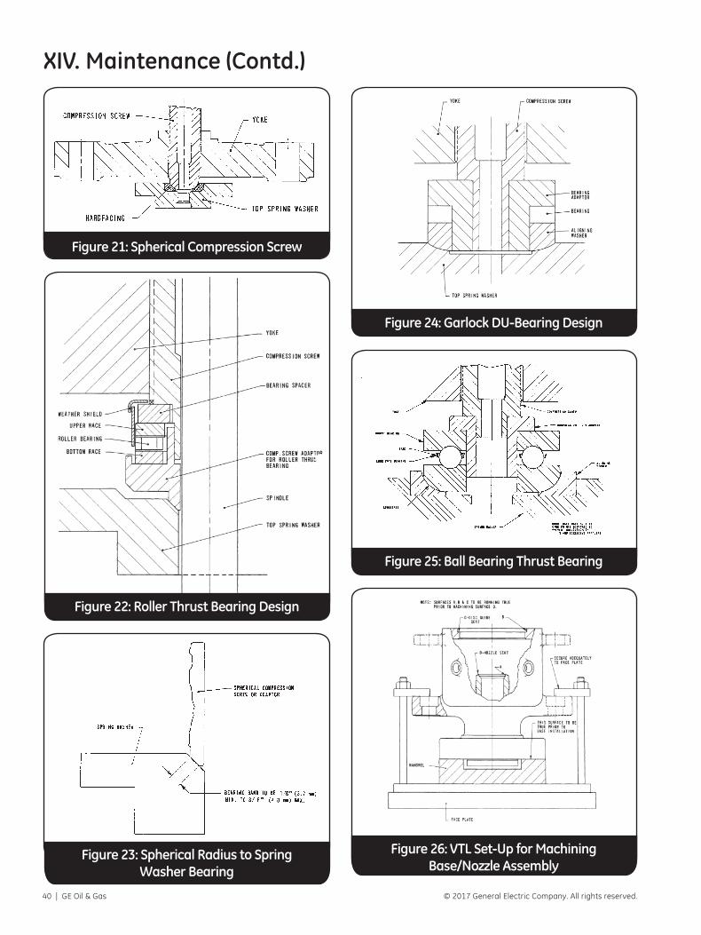
40 | GE Oil & Gas © 2017 General Electric Company. All rights reserved.
XIV. Maintenance (Contd.)
Figure 21: Spherical Compression Screw
Figure 22: Roller Thrust Bearing Design
Figure 23: Spherical Radius to Spring Washer Bearing
Figure 24: Garlock DU-Bearing Design
Figure 25: Ball Bearing Thrust Bearing
Figure 26: VTL Set-Up for MachiningBase/Nozzle Assembly

Consolidated AP1000 3707S Edition Safety Valve Maintenance Manual | 41© 2017 General Electric Company. All rights reserved.
XV. RepairA. Re-machining Nozzle Seats
When required, the nozzle seat should be machined with the nozzle assembly in the base. If it should be necessary to remove the nozzle from the base, see NOZZLE REMOVAL, Paragraph C.
B. VTL Set-UpReference Figure 26 (pg 40) for Machining of Nozzle when assembled in Base.1. Verify that the nozzle is firmly torqued into the valve
base. Refer to Paragraph F – Nozzle Installation.2. Mount the inlet flange of the valve with the nozzle
vertical.3. True up the work so that the top of the nozzle
(D) and surface (C) are parallel within .001 inches (.025mm), diameter (B) and (A) to be concentric within .002 inches (.051mm) TIR.
4. Re-establish Dimensions denoted in Paragraph E, Machining of Nozzle Seat. Dimension F is to be re-established after machining of the nozzle seat. Surface finish for all machined surfaces shall be 63 RMS or better.
5. Thoroughly clean all parts upon completion of machining operations.
C. Nozzle RemovalThe nozzle is assembled to the base with threads
and may be removed by turning counter-clockwise. To facilitate removal of the nozzle from the base it may be beneficial to first soak the threaded joint with a nuclear grade penetrating oil approved by the nuclear facility.1. Although the nozzle is rarely required to be
removed, if required, then utilize a 3 or 4 jaw chuck welded vertically to a stand bolted to a concrete floor. Chuck on nozzle flange and break the body loose from the nozzle with either a heavy rod or pipe as shown in Figure 27 (pg 42).
2. Use large pipe wrench on the nozzle flange to remove the nozzle from the base. Reference Figure 28 (pg 42).
D. Lathe Set-Up for Machining of Nozzle when Removed from Base.Reference Figure 29 (pg 42).1. Grip the nozzle in four-jaw independent chuck, using
a piece of soft material such as copper or fiber between the jaws and the nozzle as shown at A.
2 True up the nozzle so that the surfaces marked B and D are concentric within .001 inches (.025mm) TIR. Surfaces E and C should be parallel within .002 inches (.050mm). Refer to Paragraph E – machining of nozzle seat for machining dimensions. Surface finish for all machine surfaces shall be 63 RMS or better.
Machining Dimensions for Nozzle Seat (mm)
Orifice SizeA B C D† E F*
+.076-.000
+.000-1.02 ±.127 ±.076
3
Do Not Rema-chine
53.9 59.7
See nozzle section Chart
X.1
3.7 .64
4 74.4 74.4 4.5 .64
6 99.1 99.1 5.9 1.14
Q 112.3 123.8 7.5 1.14
8 127.3 140.3 8.5 1.14
R 135.1 149.3 9.0 1.14
T 179.7 198.2 10.2 1.14
S 164.4 181.6 10.9 1.14
Table 3: Machining Dimensions for Nozzle Seat (inches)
Orifice SizeA B C D† E F*
+.003-.000
+.000-.004 ±.005 ±.003
3
Do Not Rema-chine
2.122 2.350
See nozzle section Chart
X.1
.144 .0254 2.652 2.930 .179 .0256 3.537 3.902 .234 .045Q 4.421 4.875 .294 .0458 5.010 5.525 .333 .045
R/RR 5.321 5.878 .354 .045T 7.074 7.804 .400 .045S 6.472 7.150 .431 .045
E. Machining of Nozzle Seat Reference Figure 32 (pg 42) and Table 3
† See nozzle section of Chart X.1.

42 | GE Oil & Gas © 2017 General Electric Company. All rights reserved.
Figure 27: Nozzle Removal Figure 28: Nozzle Removal and Installation
F. Nozzle Installation
Replacement nozzles are shipped from the factory with the nozzle seat and inlet face completed. No additional machining is required.
Lubricate the base and nozzle threads. Screw the nozzle into the base until the backside of the nozzle flange contacts the face of the base of inlet flange.
A multiple jaw chuck designed to clamp on the outside of the nozzle flange and to attach a torque wrench shall be used. Assemble the chuck to the nozzle making sure the face of the chuck does not come in contact with the face of the base flange. Thin metal spacers can be used between the chuck and base flange to assure the chuck is not resting on the face of the base flange and then removed prior to applying torque. Mount torque wrench to chuck and torque per Table 2 (pg 43).
NOTE: A torque multiplier may be used if desired. NOTE: Nozzles (seat bushings) in bases with a butt welding end on the inlet cannot be replaced. A new base assembly would be required.
G. Yoke Rod Replacement
If a single yoke rod is to be replaced, then both yokes must be removed from the base to allow for verification of critical shoulder-to-shoulder dimension. The figures contained in paragraph X.1.18 of Chart X.1 define the location of this critical dimension.
Measure the shoulder-to-shoulder length of both yoke rods. Both dimensions must be within .008-inch of each other. If not, the yoke rod with the longer
dimensions is to be recut so both rods will be within .008-inch of each other. This also applies if both rods are replaced.
H. Extended Wear Modification
As nuclear power plants age, system vibrations tend to increase. These vibrations can increase to a point where damage to internal parts and threads will occur. For nuclear systems where safety valve damage has occurred, the valves can be modified with extended wear parts as shown in Figure 31 (pg 43). Contact GE Consolidated, for additional information such as part numbers.
XV. Repair (Contd.)
Figure 29: Lathe Set-Up for Machining Nozzle Seat
Figure 30: Machining Dimensions for Nozzle Seats

Consolidated AP1000 3707S Edition Safety Valve Maintenance Manual | 43© 2017 General Electric Company. All rights reserved.
XVI. ReassemblyTorque Value Tolerances
Tolerance range for nominal torque values given in this section is plus or minus 25%, unless otherwise specified. Calibrated torque wrenches are to be used.
A torque adjustment factor is not required when using a crows foot for tightening the cover plate or yoke rod support bolting. This variable has already been considered in the specified torque values.
Lubricants
Lubricants where specified in this section shall be per Section XXII.
1. Yoke Rod Installation
CAUTION: When replacing yoke rods, the critical shoulder-to-shoulder dimension on both rods are to be verified. See Section XII, paragraph G of this manual.
Table 4: Torque Values for Nozzle
Orifice ft-lbs Kgf-M
3 525-550 72.6-76.0
4 & 6 1375-1400 190-194
Q, 8, R, RR, & T 1875-1900 260-263
S 4800-4900 663-677
Figure 31: Extended Wear Modification
NOTE: If the spindle is nickel steel, the existing spindle can be reworked to an extended wear design.
NOTE: Depending on the condition of the head, compression screw with hexagon heads can be reworked to an extended wear design.
NOTE: The TeflonTM wear bushing and lock washers are not to reused.
NOTE: The bushing can be replaced on the assembled valve without removing the valve from the system and without disassembling the valve and without disturbing the valve set pressure or seat tightness. However, THERE SHOULD BE NO STEAM PRESSURE ON THE VALVE.
Use of an impact device to produce required
torque values is not recommended.
a. Except for the 3707T Safety valve, the yoke rods are to be installed into the base and then the yoke rod nuts installed. Locate yoke rods and nuts into the original location in the valve base by using previous identification methods. Lubricate all threads. Yoke rod nuts are then to be torqued using the yoke rod nut torque wrench (Tool P) and the socket (Tool Q). Torque values given in Table 5 (pg 44).
b. For the 3707T Safety valve, the yoke rod is to be inserted into the proper location in the valve base using previous identification methods. The yoke rod should be dropped down so that the split rings and wire retainer can be installed as shown in Figure 17 (pg 28). All parts should be lubricated. Pull up on the yoke rod engaging the lower yoke rod end with the split rings and retainer wire into the valve base lug. The bottom side of the rod should be held in position by a wood spacer between the base flange and the lower side of the yoke rod.
2. Adjusting Ring Installation
a. Lubricate the threads of the lower adjusting ring and screw onto the nozzle.
b. Lubricate the threads of the lower ring pin. Screw the ring pin into the base to engage the lower adjusting ring. The pin must engage into the ring notch, but must not bind the ring. Pins are manufactured intentionally long. Grind/cut the pin as required. There should be approximately 1/32” clearance between the tip of pin and the bottom of the notch. Engagement is to be verified with the lower adjusting ring in two different positions 180º apart. After ring fit is acceptable, loosen the ring
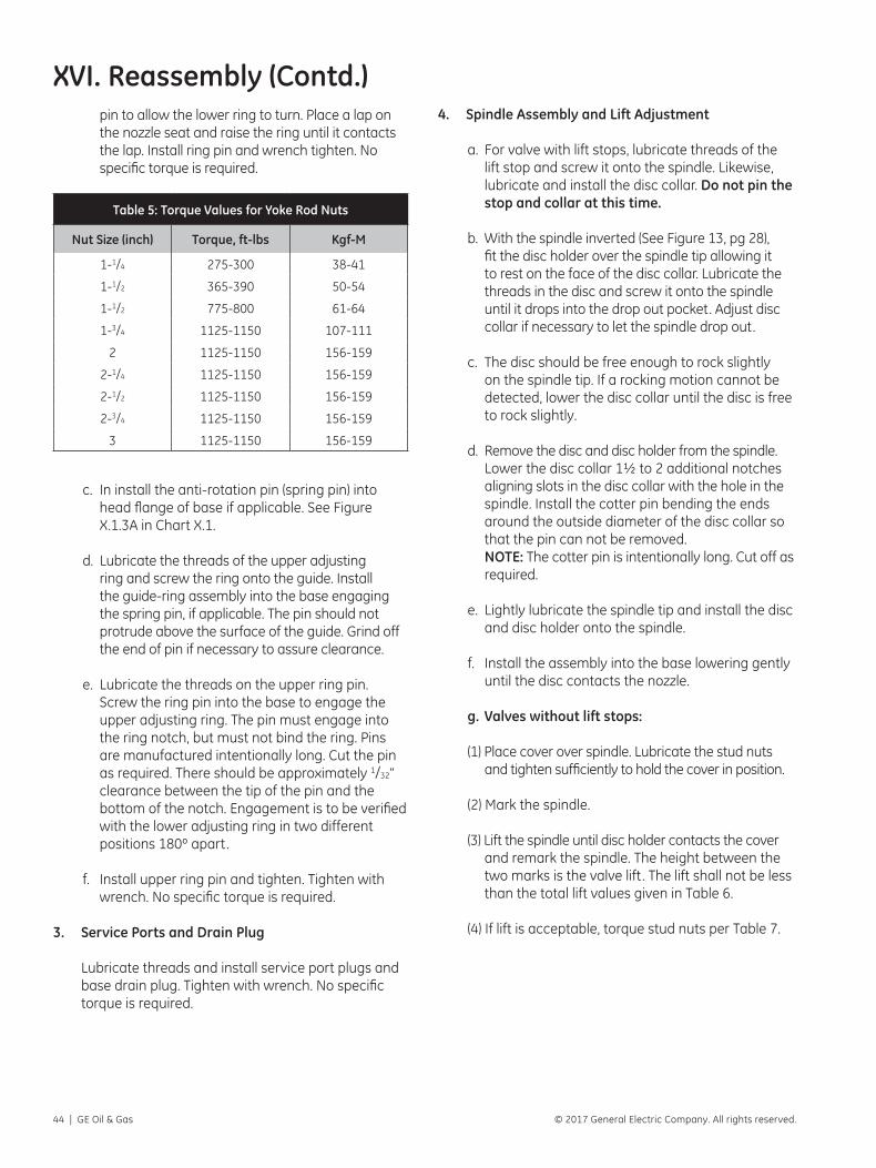
44 | GE Oil & Gas © 2017 General Electric Company. All rights reserved.
pin to allow the lower ring to turn. Place a lap on the nozzle seat and raise the ring until it contacts the lap. Install ring pin and wrench tighten. No specific torque is required.
Table 5: Torque Values for Yoke Rod Nuts
Nut Size (inch) Torque, ft-lbs Kgf-M
1-1/4 275-300 38-41
1-1/2 365-390 50-54
1-1/2 775-800 61-64
1-3/4 1125-1150 107-111
2 1125-1150 156-159
2-1/4 1125-1150 156-159
2-1/2 1125-1150 156-159
2-3/4 1125-1150 156-159
3 1125-1150 156-159
c. In install the anti-rotation pin (spring pin) into head flange of base if applicable. See Figure X.1.3A in Chart X.1.
d. Lubricate the threads of the upper adjusting ring and screw the ring onto the guide. Install the guide-ring assembly into the base engaging the spring pin, if applicable. The pin should not protrude above the surface of the guide. Grind off the end of pin if necessary to assure clearance.
e. Lubricate the threads on the upper ring pin. Screw the ring pin into the base to engage the upper adjusting ring. The pin must engage into the ring notch, but must not bind the ring. Pins are manufactured intentionally long. Cut the pin as required. There should be approximately 1/32” clearance between the tip of the pin and the bottom of the notch. Engagement is to be verified with the lower adjusting ring in two different positions 180º apart.
f. Install upper ring pin and tighten. Tighten with wrench. No specific torque is required.
3. Service Ports and Drain Plug
Lubricate threads and install service port plugs and base drain plug. Tighten with wrench. No specific torque is required.
4. Spindle Assembly and Lift Adjustment
a. For valve with lift stops, lubricate threads of the lift stop and screw it onto the spindle. Likewise, lubricate and install the disc collar. Do not pin the stop and collar at this time.
b. With the spindle inverted (See Figure 13, pg 28), fit the disc holder over the spindle tip allowing it to rest on the face of the disc collar. Lubricate the threads in the disc and screw it onto the spindle until it drops into the drop out pocket. Adjust disc collar if necessary to let the spindle drop out.
c. The disc should be free enough to rock slightly on the spindle tip. If a rocking motion cannot be detected, lower the disc collar until the disc is free to rock slightly.
d. Remove the disc and disc holder from the spindle. Lower the disc collar 1½ to 2 additional notches aligning slots in the disc collar with the hole in the spindle. Install the cotter pin bending the ends around the outside diameter of the disc collar so that the pin can not be removed. NOTE: The cotter pin is intentionally long. Cut off as required.
e. Lightly lubricate the spindle tip and install the disc and disc holder onto the spindle.
f. Install the assembly into the base lowering gently until the disc contacts the nozzle.
g. Valves without lift stops:
(1) Place cover over spindle. Lubricate the stud nuts and tighten sufficiently to hold the cover in position.
(2) Mark the spindle.
(3) Lift the spindle until disc holder contacts the cover and remark the spindle. The height between the two marks is the valve lift . The lift shall not be less than the total lift values given in Table 6.
(4) If lift is acceptable, torque stud nuts per Table 7.
XVI. Reassembly (Contd.)

Consolidated AP1000 3707S Edition Safety Valve Maintenance Manual | 45© 2017 General Electric Company. All rights reserved.
Table 6: Lift Values
Valve Type Min, rated lift, (mm)
Allowance, in (mm)
Total Lift, in (mm)
3737 .450 (11.4) .030 (.8) .480 (12.2)
3747 .563 (14.3) .030 (.8) .593 (15.1)
3767 .750 (19.0) .030 (.8) .780 (19.8)
3777Q .938 (23.8) .040 (1.0) .978 (24.8)
3787 1.063 (27.0) .040 (1.0) 1.103 (28.0)
3707R 1.129 (28.7) .050 (1.3) 1.179 (30.0)
3707RR 1.240 (31.5) .050 (1.3) 1.290 (32.8)
3707T 1.500 (38.1) .060 (1.5) 1.560 (39.6)
3707S 1.590 (40.4) n/a n/a
h. Valves with lift stops:
NOTE: For the AP1000 3707S series valves, the lift stop should be screwed till it hits a hard stop. Back out to line up the cotter pin slot and holes. Install the cotter pin bending the ends. The cotter pin is intentionally long. Cut off the ends as required.
(1) Place cover or yoke rod support over the spindle. Lubricate and tighten the stud nuts sufficiently to hold the cover plate or yoke rod support in position. For lift adjustment, the yoke rod support may be rotated so it does not engage the yoke rods.
(2) Mark the spindle.
(3) Lift the spindle until the lift stop contacts the cover plate or yoke rod support and remark the spindle. The height between the two marks is the valve lift. The lift shall not be less than the total lift values given in Table 6, except for valves with restricted lift. For restricted lift valves, the lift should be adjusted to the value given on the nameplate or on the as-built construction drawing. The allowance lift given in Table 6 shall be added to the restricted lift value to calculate the Total Lift.
(4) If necessary, adjust the lift stop and repeat the process.
(5) If lift is acceptable, install the cotter pin bending the ends around the outside diameter of the lift stop so that the pin cannot be removed. NOTE: The cotter pin is intentionally long. Cut off as required.
(6) If with cover: install cover stud nuts and torque per Table 7.
XVI. Reassembly (Contd.)(7) If with yoke rod support: remove the yoke rod
support.
Table 7: Torque Values for Cover & Yoke Rod Support Bolting
Stud Size, in. Torque, ft-lbs Torque, Kgf-M1/2 30-45 4-65/8 60-75 8-103/4 100-125 13-17
1 100-125 13-17
1-1/8 195-220 26-30
1-1/4 275-300 38-41
5. Spring Assembly
a. Grind lower spring washer to spindle if not previously performed.
b. For valve with cover: Lightly lubricate bearing surfaces and install lower washer onto the spindle.
c. For valves with yoke rods supports: Slowly lower the yoke rod support into position letting the ears engage the yoke rods. Lubricate bolting and secure with nuts. Torque per Table 7. A crowfoot may be used. Torque adjustment when using a crowfoot is not required for this bolting.
d. Lubricate the bearing surface of the lower spring washer and install.
e. Install the spring. NOTE: The spring can be lifted by using a flat plate with an eye hole in the center. The plate is passed between the coils at the top end of the spring and a J-hook is passed through the eye in the plate at the center of the spring. Then the J-hook can be connected to a chain hoist.
6. Compression Screw to Top Spring Washer Interface
a. Type 1, Figure 21 (pg 40): The tip of the compression screw has a spherical radius and the mating surface of the top spring washer is a 45º angle. Grind compression screw into the top spring washer if not previously performed. Lightly lubricate the bearing surface of the top washer and install. If the washer has an arm, the arm shall engage a yoke rod to prevent rotation.

46 | GE Oil & Gas © 2017 General Electric Company. All rights reserved.
b. Type 2, Figure 24 (pg 40): The assembly consists of the compression screw, an adaptor, a friction washer, a lower support and the top spring washer. Grind lower support into top spring washer. Lightly lubricate the bearing surface of the top washer and install. Lightly lubricate the friction washer on both sides. Assemble the lower support, the friction washer and the adaptor. Position the assembly onto the spring washer.
c. Type 3, Figure 25 (pg 40): The assembly consists of the compression screw, an adaptor, a thrust bearing, an alignment washer and the top spring washer. The bearing-aligning washer unit is pre-ground. Lightly lubricate the bearing surface of the alignment washer. Pack the thrust bearing with lubricant. Lightly lubricate the bearing surface of the top spring washer. Assemble the aligning washer, the thrust bearing and the adaptor. Position the assembly on the spring washer.
d. Type 4, Figure 25 (pg 40): This assembly is the same as Type 3 except there is no alignment washer. The bearing is to be ground into the top spring washer. Otherwise, comply with paragraph c above.
e. Type 5, Figure 22 (pg 40): The assembly consists of the compression screw, an adaptor, a rolling bearing, a lower support, and the top spring washer. This type may also have a dust cover. Grind the lower support into top spring washer. Lightly lubricate surface of spring washer and install. Pack the roller bearing with lubricant. Assemble the lower support, the thrust support, the thrust over the assembly when applicable.
f. Type 6, Figure 23 (pg 40): The assembly consists of a compression screw, an adapter or plunger and the top spring washer. Grind the adapter/plunger nose into top spring washer. Lightly lubricate surface of spring washer and install.
7. Yoke and Compression Screw Assembly
a. Lubricate the threads on the compression screw. Screw the locknut onto the compression screw. Screw the compression screw into the yoke until the top protrudes the same amount that was recorded on disassembly. Lightly lubricate the outside of the tip.
b. Lower the yoke onto the valve engaging the yoke rods and bearing assembly when applicable.
XVI. Reassembly (Contd.)c. Lubricate the threads of the yoke rods and secure
with nuts. Compress the spring using the hydraulic tool shown in Figure 12 (pg 28) or tool 1582 shown in Figures 34A and 34B (pg 50). Tighten the yoke rod nuts uniformly to seat the yoke and torque per Table 5 (pg 44). It may be necessary to tighten the yoke rod nuts as the spring is being compressed.
d. Set the compression screw back to its original position recorded during disassembly. See Figure 11 (pg 27).
8. Extended Wear Modification
a. Split the TeflonTM bushing into two equal halves. Straight, smooth vertical cuts are required.
b. Install the two halves of the bushing into the head of the compression screw as shown in Figure 31 (pg 43). Remove both ring pins and adjust both rings level with the seat.
c. Install retaining washer, lock washers, and cap screws. Torque cap screws to 70-76 in-lbs. NOTE: always use new lock washers.
9. Adjusting Ring Adjustment
a. The lower ring was previously set level with the nozzle seat. Now, backing off the lower adjusting ring pin to allow the ring to turn. Adjust clockwise the number of notches given in Table 8 (pg 47) except for valves that have been blowdown tested. Tighten the ring pin making sure the pin is engaging and is not hitting the outer ridge of the notch. The ring should free to rock back and forth.
b. Back off the upper ring pin to allow the upper adjusting ring to turn. Reaching into outlet, adjust the ring until the bottom surface of the ring is aligned with the bottom surface of the disc holder. Now adjust the ring per Table 8 (pg 47) except for a valve that has been blowdown tested.
c. Bar gages are available for setting the adjusting rings for the 3777Q, 3787, 3707R and the 3707RR safety valves. The bar gage sets the adjusting rings to the setting in Table 8 (pg 47) but does not require counting notches. The gage sets against the bottom of the disc holder and the adjusting rings are turned until they contact the gage. See Figure 32 (pg 47).
d. For valves blowdown tested, the adjusting rings are to be adjusted to the number of notches given on the ring position nameplate attached to the valve.

Consolidated AP1000 3707S Edition Safety Valve Maintenance Manual | 47© 2017 General Electric Company. All rights reserved.
e. After setting the adjusting rings, wire and seal the adjusting ring pins. The valve is now ready for steam testing.
10. Steam Testing
a. Flange protectors are required when transporting to test facility. The safety valve shall be kept in the vertical position at all times.
Table 8: Adjusting Ring Settings for 3-9% Blowdown
For 3-9% Blowdown
Valve Type Lower Ring1 Upper Ring2
3737 -3 +82
3747 -4 +94
3767 -5 +112
3777Q -8 +160
3787 -8 +160
3707R -8 +160
3707RR -8 +160
3707T -8 +160
Notes: (1) Minus (-) means below the nozzle seat and plus (+) means above
the nozzle seat.
(2) Minus (-) means below the disc holder and plus (+) means above the disc holder.
Figure 32: Adjusting Ring Gauge
11. Final Assembly Steps After Acceptable Steam Test
a. Cap Assembly – Valves with Lifting Levers:
(1) Lubricate the threads in the release nut. Screw the release nut onto the spindle. Install the cap and tighten the locking screw(s).
(2) Assemble the top lever to the cap securing with the lever pin. Assemble the drop lever to the cap securing with the lever pin and a cotter pin. Cut the cotter pin off as required. The ends of the cotter pin are to be separated and bent.
(3) Adjust the release nut to align with the slots with the existing cotter pin hole in the spindle. There should be approximately 1/32”-3/32” clearance between the release nut and the top lever. If it is a new spindle, adjust the release nut to provide the proper clearance. In either case, mark the position of the release nut on the spindle. Remove the top lever and then remove the cap.
(4) For new spindles, at the marked location drill the spindle (9/64” diameter) using the slots in the release nut as a guide. Secure the release nut with a cotter pin. The pin is intentionally long. Cut off as required. The ends of the cotter pin are to be separated and bent.
(5) Install the cap on the valve. Tighten the locking screw(s) with a wrench. Only square head set screws with knurl points are to be used. No specific torque is required. Install the top lever on the cap securing with the lever pin and a cotter pin. Cut off as required. The ends of the cotter pin are to be separated and bent.
(6) Wire and seal the cap.
(b) Cap Assembly – Valves without Lifting Levers:
(1) Install the cap on the valve. Tighten the locking screw(s) with a wrench. Only square head set screws with knurl points are to be used. No specific torque is required
(2) Wire and seal the cap.
(3) Install gag plug, if applicable.
(c) Install a ring position tag plate and a repair tag plate.

48 | GE Oil & Gas © 2017 General Electric Company. All rights reserved.
XVII. Field SettingsA. Set Pressure Adjustment
B. Blowdown Adjustment
C. Adjusting Ring Positions
XVIII. Sealing Valves After TestAfter testing the valve for proper set point and blowdown, the ring pins and top lever pin will be sealed to conform with ASME Section III.
Means are provided in the design of all 3700 Series Safety valves for use under this section of the code for sealing all external adjustments. Seals are installed by GE on the assembly at the time of initial shipment at the plant, and are required to be installed after field adjustments or repair of the valves by either the manufacturer, their authorized representative repairer, or the user.
Seals should be installed in such a manner as to prevent changing the adjustment without breaking the seal and, in addition shall serve as a means of identifying the manufacturer, repairer, or user making the adjustment. Unauthorized breakage of the seals will void the valve warranty.
Figure 33: Gagging Arrangement
XIX. Gagging ProcedureDuring any operational hydrostatic test all safety valves on the unit must be gagged. This gagging procedure prevents the possibility of damage to the safety valve internals if the test pressure exceeds the safety valve set pressure. When adjusting valve set pressure, other valves in the system should also be gagged.
Probably the most common source of safety valve trouble is over-gagging. During hydrostatic testing, and during safety valve setting, gags should be applied only finger tight. During setting, over-gagging will also cause damage to the seating surface and resultant leakage. In applying gags, remember that the valve spring will hold the valve closed against its set pressure. The additional gag load applied should be only enough to ensure that the valves do not lift at the expected over-pressure.
When operating on steam, gags should never be applied when valve is cold. The spindle of the safety valve expands considerably when the temperature increases as pressure is raised. If it is not free to expand with this temperature change, it may become bent. Header pressure should be
brought up to within 80% of the pressure of the low set valve before applying gags. Tighten the gags initially with only a light force applied to the gag screw head.
To properly apply gags, the following steps should be followed:
1. Remove the top lever pin, top lever and then loosen the cap screw. Remove the cap and drop lever as assembly.
2. The gag shown in Figure 33 (pg 48) is to be used. Refer to the GA drawing for the AP1000 3707S gag part number. NOTE: Do not apply the gag load until the system hydrostatic pressure or steam pressure is equal to 80% of the pressure to which the low set valve is adjusted.
3. Apply the gag load by turning the gag screw clockwise. If the gag on any valve has not been tightened sufficiently, the valve will leak. On steam service the leakage is accompanied by “Sizzling” sound.
IN COURSE OF PREPARATION CONTACT FACTORY FOR INFORMATION

Consolidated AP1000 3707S Edition Safety Valve Maintenance Manual | 49© 2017 General Electric Company. All rights reserved.
XX. Setting the valve set pressure using the AP1000 3707S Hydraulic Set Device (See Figures 34A and 34B, pg 50)The AP1000 3707S set device kit (patent pending) is used for the following purposes,
a) Setting the set pressure of the valve,
b) Checking the set pressure of the valve by using it as an auxiliary lift device, and
c) Performing the jacking of the bonnet assembly without affecting valve set pressure.
The set device kit consists of the following parts
• Enerpac single acting hydraulic cylinder, 7473728 (1x)
• Enerpac – 20’ hydraulic hose, 7473729 (1x)
• Swagelok 2 way ball valve, 7473777 (1x)
• Bonnet connection, 7520601 (1x)
• Lift step, 7520701 (1x)
• Spindle connection, 7520801 (1x)
• Plunger connection, 7520901 (1x)
• Spacer plate, 1571375 (1x)
• Set device studs, 1.00-8 UNC, 7520501 (3x)
• Heavy hex nuts, 1.00-8 UNC, 2203611 (3x)
• Heavy hex nut, 1.25- 8 UN, 2200218 (1x)
• Heavy hex nut, 1.75-8 UN, 2205033 (1x)
Setting the Valve Set pressure
1. Remove the Bonnet Cap and Cap Screws
2. Install the spindle connection by threading it till it makes a hard stop
3. Install the plunger connection till it rests on the plunger
4. Install the lift step on the plunger. Ensure about 0.250 inches is available between the lift step and the compression screw and that the lift step is below the top surface of the plunger connection
5. Install the set device studs until a hard stop is achieved
6. Place the spacer plate on top of the plunger connection
7. Place the bonnet connection on top of the set device stud shoulder.
8. Install the hydraulic cylinder onto the bonnet connection to engage the entire thread length. The hydraulic cylinder ram should be in contact with or slightly above the spacer plate
9. Install three (3x) upper set device hex nuts and torque to 1/8 turn after hand tight
10. Connect the hydraulic cylinder to the hydraulic pump with a T-connection fitting. Install the ¼ turn ball valve on the T-connection. The ball valve may be connected to a calibrated pressure gage to measure pump pressure.
11. Increase the hydraulic pressure to compress the spring. See Table below for correlation of the hydraulic pressure to the valve set pressure. Note: This is for information only. The valve set pressure can only be accurately determined with bench testing or testing with the hydraulic lift assist device.
NOTE: If this occurs, the hydrostatic test pressure or steam pressure should be reduced until the valve becomes tight and then the gag should be tightened still further. For the AP1000 3707S MSSV the torque applied during gag tests is 200 ft-lbs and shall not exceed 265 ft-lbs.
This procedure must be followed exactly since it is very difficult to stop the leak by additional gagging once it has started. Any attempt to stop the leakage through
the valve without first lowering the system pressure could result in damage to the valve seats.
4. After the hydrostatic test or steam test is completed, the gags should be removed when the hydrostatic pressure has been reduced to 80% to 90% of the pressure of the low set valve. NOTE: Under no circumstances should the gag be left on the valves.

50 | GE Oil & Gas © 2017 General Electric Company. All rights reserved.
Set Pressure (psig) Compressive Force (lbf) Pump Pressure (psig)
1185 (1173-1197) 39,816 (39413-40219) 6490
1197 (1185-1209) 40,219 (39816-40622) 6558
1209 (1197-1221) 40,622 (40219-41026) 6624
1221 (1209-1233) 41,026 (40622-41429) 6691
1232 (1220-1244) 41,395 (40992-41798) 6750
NOTE: Pump pressure shall not exceed 10,000 psig.
12. Rotate the compression screw until a hard stop with the plunger is achieved.
13. Vent the hydraulic pressure and remove the components reversing the assembly steps
Figure 34A: Hydraulic Set Device Layout for Set Pressure Adjustment
Figure 34B: Hydraulic Set Device Settings for Set Pressure Adjustment
14. The set up can be used during bench testing to adjust the set pressure of the valve
15. After verification of the set pressure, the cap/cap screws can be installed
Spindle Adapter
Hydraulic Cylinder
Bonnet Plate
Spacer Plate
Studs
Lift Step
Plunger Adapter
Contact - Plunger and plunger adapter

Consolidated AP1000 3707S Edition Safety Valve Maintenance Manual | 51© 2017 General Electric Company. All rights reserved.
XXI. Using the AP1000 3707S Hydraulic Set Device as an auxiliary lift device to check the set pressure of the valve during service or with bench testing (See Figures 35A and 35B, pg 52)NOTE: To use the AP1000 3707S Hydraulic Set Device as
an auxiliary lift device to verify set pressure, the inlet pressure shall be between 60-80% of the valve set pressure. Do not use the set device to check set pressure of the valve with inlet pressure less than 60% of set pressure.
1. Remove the Bonnet Cap and Cap Screws
2. Install the spindle connection by threading it till it makes a hard stop
3. Install the plunger connection till it rests on the plunger
4. Install the lift step on the plunger. Ensure about 0.250 inches is available between the lift step and the compression screw and that the lift step is below the top surface of the plunger connection
5. Install the set device studs until a hard stop is achieved
6. Place the spacer plate on top of the plunger connection
7. Place the bonnet connection on top of the set device stud shoulder
8. Install the hydraulic cylinder onto the bonnet connection to engage the entire thread length. The hydraulic cylinder ram should be in contact with or slightly above the spacer plate
9. Lift the plunger connection approximately ½ inch. The lift step and spacer plate will move with the plunger connection. While the plunger connection is lifted and not contacting the plunger, rotate the lift step until it contacts the compression screw. The plunger connection, lift step, and load cell should be sitting on the compression screw while approximately ½ inch space will be available for the auxiliary lift device
10. Install the spindle set device nut, 1.25- 8UN Heavy hex nut, on the spindle connection till hard stop is achieved against the hydraulic ram body.
11. Connect the hydraulic cylinder to the hydraulic pump with a T-connection fitting. Install the ¼ turn ball valve on the T-connection. The ball valve is to be connected to a calibrated pressure gage to measure pump pressure. It is recommended that a peak pressure readout be provided on the pressure gage.
12. Increase the hydraulic pressure to provide the auxiliary lift. The valve set pressure can be observed as a change in slope in the pump pressure readout and by the movement of the bonnet plate. Record the pump pressure at this instant. To calculate the set pressure of the valve, the inlet pressure at the valve should be available. The formula below can be used to determine the set pressure of the valve.
Pset = Pinlet + Ppump
13. Vent the hydraulic pressure and remove the components reversing the assembly steps
14. After verification of the set pressure, the cap/cap screws can be installed.
4.76
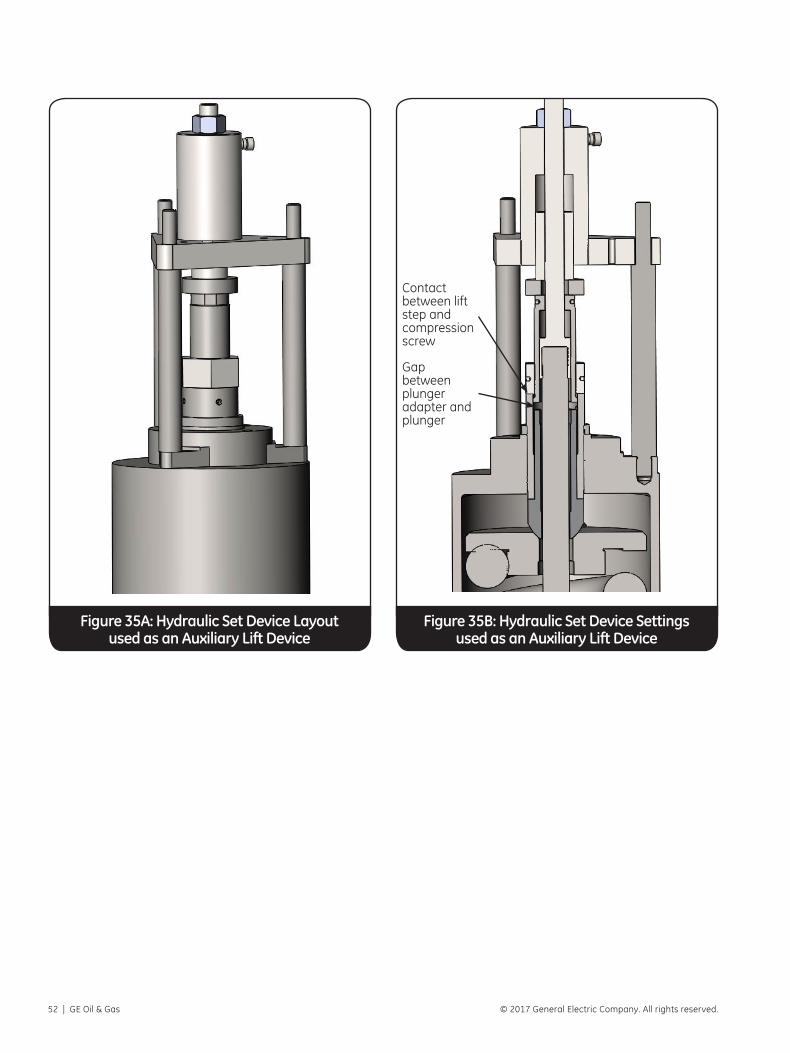
52 | GE Oil & Gas © 2017 General Electric Company. All rights reserved.
Figure 35A: Hydraulic Set Device Layout used as an Auxiliary Lift Device
Figure 35B: Hydraulic Set Device Settings used as an Auxiliary Lift Device
Contact between lift step and compression screw
Gap between plunger adapter and plunger

Consolidated AP1000 3707S Edition Safety Valve Maintenance Manual | 53© 2017 General Electric Company. All rights reserved.
Problem Probable Cause Corrective Action
No Action, valve does not go into full lift
A. Upper ring too highB. Foreign material trapped between disc holder
and guide
A. Increase blowdown as outlined in manual.B. Disassemble valve and correct discrepant
condition as outlined in manual. Inspect system for cleanliness.
Hang-up, or valve does not close from full lift
A. Lower ring too highB. Foreign material between disc & nozzle
A. Move lower ring to the left one notch per adjustment until problem is eliminated.
B. Disassemble valve and correct discrepant condition as outlined in manual. Inspect system for cleanliness.
Excessive blowdownA. Upper ring too lowB. Exhaust pressure too high
A. Decrease blowdown as outlined in manual. B. Decrease exhaust pressure by increasing
discharge stack area.
Valve leaking and/or exhibits erratic popping action
A. Damaged seatB. Part misalignment C. Disc has insufficient rockD. Discharge stack binding on outlet
A. Disassemble valve, lap seating surfaces, replace disc if required as outlined in manual.
B. Disassemble valve, inspect contact area of disc and nozzle, lower spring washer or spindle, compression screw, spindle straightness, etc., as outlined in manual.
C. Disassemble valve, inspect contact area of disc and nozzle, lower spring washer or spindle, compression screw, spindle straightness, etc., as outlined in the manual.
D. Correct as required.
SimmerA. Lower ring too lowB. Steam line vibrations
A. Adjust per manual.B. Investigate and correct cause.
XXII. TroubleshootingThe following table indicates the difficulties which may be encountered, the most probable cause, and the necessary corrective action.
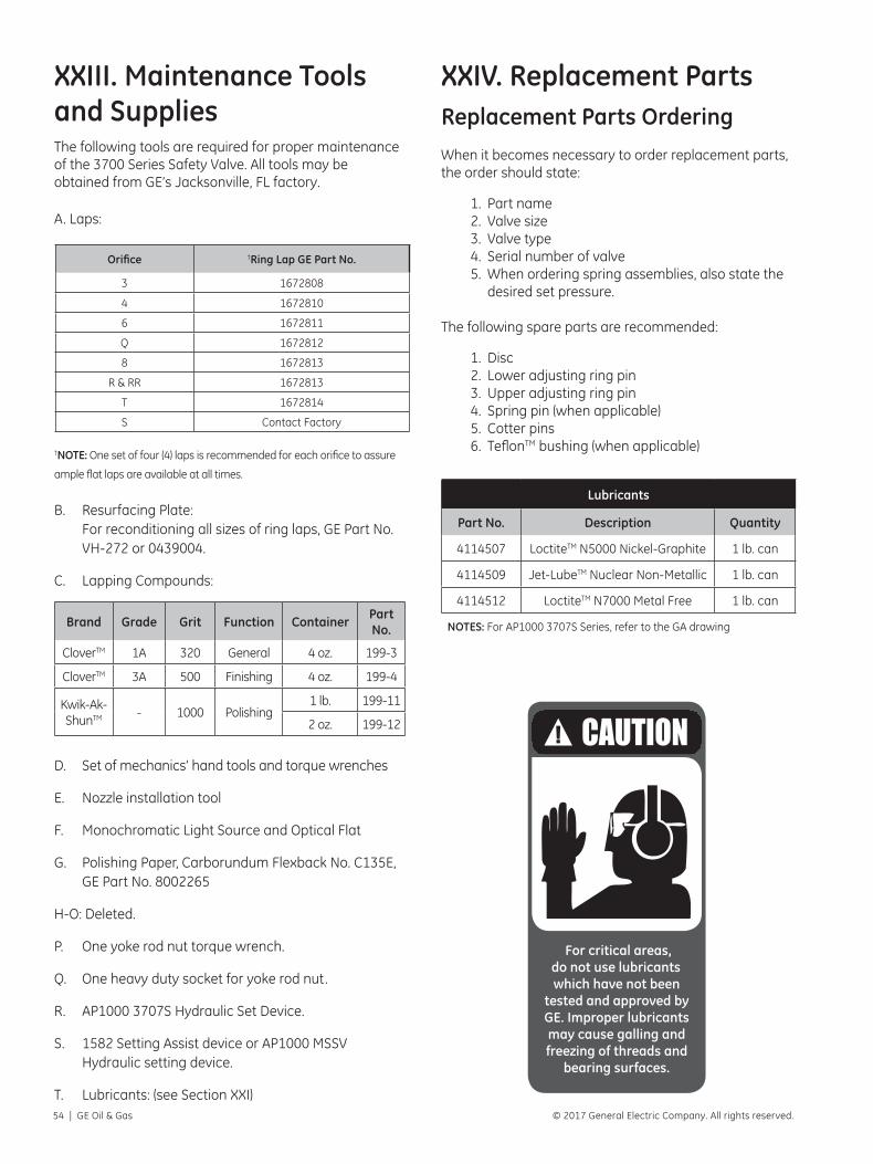
54 | GE Oil & Gas © 2017 General Electric Company. All rights reserved.
XXIII. Maintenance Tools and SuppliesThe following tools are required for proper maintenance of the 3700 Series Safety Valve. All tools may be obtained from GE’s Jacksonville, FL factory.
A. Laps:
Orifice †Ring Lap GE Part No.
3 1672808
4 1672810
6 1672811
Q 1672812
8 1672813
R & RR 1672813
T 1672814
S Contact Factory
†NOTE: One set of four (4) laps is recommended for each orifice to assure
ample flat laps are available at all times.
B. Resurfacing Plate: For reconditioning all sizes of ring laps, GE Part No. VH-272 or 0439004.
C. Lapping Compounds:
Brand Grade Grit Function Container Part No.
CloverTM 1A 320 General 4 oz. 199-3
CloverTM 3A 500 Finishing 4 oz. 199-4
Kwik-Ak-ShunTM - 1000 Polishing
1 lb. 199-11
2 oz. 199-12
D. Set of mechanics’ hand tools and torque wrenches
E. Nozzle installation tool
F. Monochromatic Light Source and Optical Flat
G. Polishing Paper, Carborundum Flexback No. C135E, GE Part No. 8002265
H-O: Deleted.
P. One yoke rod nut torque wrench.
Q. One heavy duty socket for yoke rod nut.
R. AP1000 3707S Hydraulic Set Device.
S. 1582 Setting Assist device or AP1000 MSSV Hydraulic setting device.
T. Lubricants: (see Section XXI)
XXIV. Replacement PartsReplacement Parts OrderingWhen it becomes necessary to order replacement parts, the order should state:
1. Part name2. Valve size3. Valve type4. Serial number of valve5. When ordering spring assemblies, also state the
desired set pressure.
The following spare parts are recommended:
1. Disc2. Lower adjusting ring pin3. Upper adjusting ring pin4. Spring pin (when applicable)5. Cotter pins6. TeflonTM bushing (when applicable)
Lubricants
Part No. Description Quantity
4114507 LoctiteTM N5000 Nickel-Graphite 1 lb. can
4114509 Jet-LubeTM Nuclear Non-Metallic 1 lb. can
4114512 LoctiteTM N7000 Metal Free 1 lb. can
NOTES: For AP1000 3707S Series, refer to the GA drawing
For critical areas, do not use lubricants which have not been
tested and approved by GE. Improper lubricants may cause galling and freezing of threads and
bearing surfaces.

Consolidated AP1000 3707S Edition Safety Valve Maintenance Manual | 55© 2017 General Electric Company. All rights reserved.
Factory Setting Vs. Field SettingEvery Consolidated Safety Valve is tested on steam before shipment from the factory. It must be recognized that actual field operating conditions may vary considerably from factory test conditions.
Conditions beyond the manufacturer’s control that affect valve operation are:
A. Quantity of steam being discharged through the valve.
B. Quality of steam being discharged.
C. Discharge piping stresses and back pressure.
D. Ambient temperature.
E. Shipping or storage damage.
F. Improper bolting of flanges.
G. Damage due to foreign material in the steam.
Field ServiceAll Field Service Engineers’ activities are coordinated from GE’s Jacksonville, FL factory.
Contact: Field Service & Repair Department 1-844-VALVE-GE or 1-281-884-1000
Shipment of Nuclear Valves to GE for Repair
Customer ResponsibilityDecontamination of all radioactively contaminated products to be returned to GE shall be such that any residual “removable” emitting contaminant on any internal or external surface of the product shall not exceed 0.02 microcuries as determined by standard wipe test analysis.
Any product which has either non-removable contaminants or is internally activated in the structural matrix shall be considered unacceptable if readings
taken on any surface of the product exceed 2.0 mr/hr. above normal background reading when measured with a thin end-window type probe Geiger-Müller survey meter.
The customer’s health physics department shall report in triplicate acceptable results of wipe test analysis and survey measurements, together with product service application (primary or secondary loops, etc.). The report shall be forwarded to GE’s Field Service Manager prior to return of product to GE.
Results in excess of those set forth herein will not be acceptable to GE
The customer shall, for each shipment, include on the bill of lading and on each shipping container the following conspicuous wording:
MARK: “RADIOACTIVE SERVICE”
Service WarrantyBoth factory and field repaired valves carry a warranty which covers workmanship and new parts installed during repair, for a period of one year from date or repair completion.
Product Repair By Unauthorized SourcesGE has authorized no outside repair companies, contractors, nor individuals to perform warranty repair service on new products, field or factory repair products of its manufacture. Therefore, customers contracting such repair services from unauthorized sources must do so at their own risk. Likewise, if any product fails to perform within the scope of its design, we must be notified and given the opportunity to inspect and correct the product. We will accept no back charges for unauthorized repair sources performing corrective repairs on our products.
Personnel TrainingPractical classroom training of personnel in nuclear valve repair can be provided by GE either at the factory or at the Utility. Arrangements can be scheduled.
The GE Field Service Organization is unequaled.
Manufacturer’s Field Service and Repair Program

56 | GE Oil & Gas © 2017 General Electric Company. All rights reserved.

AUSTRALIABrisbane:Phone: +61-7-3001-4319Fax: +61-7-3001-4399
Perth:Phone: +61-8-6595-7018Fax: +61 8 6595-7299
Melbourne:Phone: +61-3-8807-6002Fax : +61-3-8807-6577
BELGIUMPhone: +32-2-344-0970Fax: +32-2-344-1123
BRAZILPhone: +55-19-2104-6900
CHINAPhone: +86-10-5689-3600Fax: +86-10-5689-3800
FRANCECourbevoiePhone: +33-1-4904-9000Fax: +33-1-4904-9010
GERMANYRatingenPhone: +49-2102-108-0Fax: +49-2102-108-111
INDIAMumbaiPhone: +91-22-8354790Fax: +91-22-8354791
New DelhiPhone: +91-11-2-6164175Fax: +91-11-5-1659635
ITALYPhone: +39-081-7892-111Fax: +39-081-7892-208
JAPANTokyo Phone: +81-03-6871-9008Fax: +81-03-6890-4620
KOREAPhone: +82-2-2274-0748Fax: +82-2-2274-0794
MALAYSIAPhone: +60-3-2161-0322Fax: +60-3-2163-6312
MEXICOPhone: +52-55-3640-5060
THE NETHERLANDSPhone: +31-15-3808666Fax: +31-18-1641438
RUSSIAVeliky NovgorodPhone: +7-8162-55-7898Fax: +7-8162-55-7921
MoscowPhone: +7 495-585-1276Fax: +7 495-585-1279
SAUDI ARABIAPhone: +966-3-341-0278Fax: +966-3-341-7624
SINGAPOREPhone: +65-6861-6100Fax: +65-6861-7172
SOUTH AFRICAPhone: +27-11-452-1550Fax: +27-11-452-6542
SOUTH & CENTRAL AMERICA AND THE CARIBBEANPhone: +55-12-2134-1201Fax: +55-12-2134-1238
SPAINPhone: +34-93-652-6430Fax: +34-93-652-6444
UNITED ARAB EMIRATESPhone: +971-4-8991-777Fax: +971-4-8991-778
UNITED KINGDOMBracknellPhone: +44-1344-460-500Fax: +44-1344-460-537
SkelmersdalePhone: +44-1695-526-00Fax: +44-1695-526-01
UNITED STATESJacksonville, FloridaPhone: +1-904-570-3409
Corpus Christi, Texas Phone: +1-361-881-8182Fax: +1-361-881-8246
Deer Park, TexasPhone: +1-281-884-1000Fax: +1-281-884-1010
Houston, TexasPhone: +1-281-671-1640Fax: +1-281-671-1735
DIRECT SALES OFFICE LOCATIONS
*Denotes a trademark of the General Electric Company.
Other company names and product names used in this document are the registered trademarks or trademarks of their respective owners.
©2017 General Electric Company. All rights reserved.
GEA32970 01/2017
www.geoilandgas.com/valves


![AP1000 Installation Guide eng 040623 Guide_eng.pdf[Organization] The VoiceFinder AP1000 VoIP Gateway Installation Guide is offered to assist the ... VoiceFinder AP1000 VoIP Gateway](https://img.pdfslide.net/doc/110x75/6023a9082d103d7c1a084ddd/ap1000-installation-guide-eng-040623-guideengpdf-organization-the-voicefinder.jpg)