Embed Size (px)
Citation preview

Construction Monitoring
For Earth Dams
Reasons for Construction Monitoring
� Ensure proper materials are used
� Ensure proper construction and design is
followed
� Quickly modify design and construction
practices based on encountered site conditions
IT IS IMPERATIVE TO HAVE FULL TIME SITE INSPECTION
Inspection Requirements
� Must not hinder or slow down contractor
� Must work with contractor
� Must consider contractor construction
practices
Construction Monitoring
MATERIALS
� Grain size distribution analysis of
materials
� Core, filters, drains
� Make sure material installed meets specifications
� Make sure that the borrow materials do not change…
Construction Monitoring
MATERIAL tests
� Triaxial extension/shear – filter and core
� Consolidation – core mv
� Hydraulic conductivity
� Lab tests:
� filters - Constant or falling head
� core – triaxial
� Field clay:
� Double ring infiltrometer
� Centrifuge permeanometer
Construction Monitoring
Proctor Tests
� Source materials in borrow pit
� Materials hauled to site
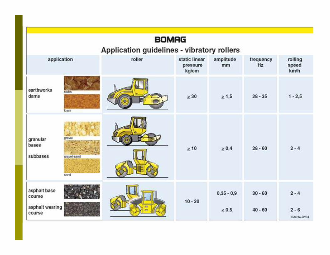
� Field Compaction
� Uncompacted layer thickness (300mm max)
� Compaction equipment is suitable
� Moisture content and Maximum dry density � Nuclear Density, sand cone, rubber balloon
� Make sure Nuclear density is calibrated
Goal of Compaction
� Place loose soil in the field and compact it to make soil strong as possible
� Maximum shear strength
� Very little settlement
� Low hydraulic conductivity
� Find soil lowest emin ……highest dry unit weight

Knead Clay Chunks
Sheepsfoot roller
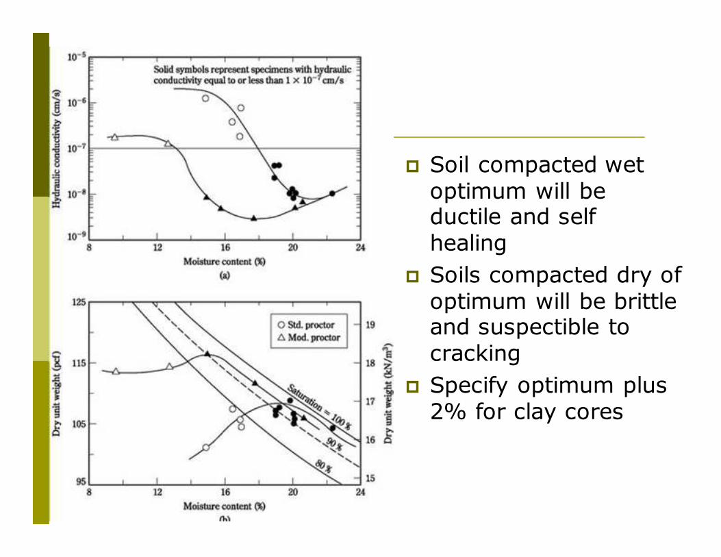
� Soil compacted wet optimum will be ductile and self healing
� Soils compacted dry of optimum will be brittle and suspectible to cracking
� Specify optimum plus 2% for clay cores
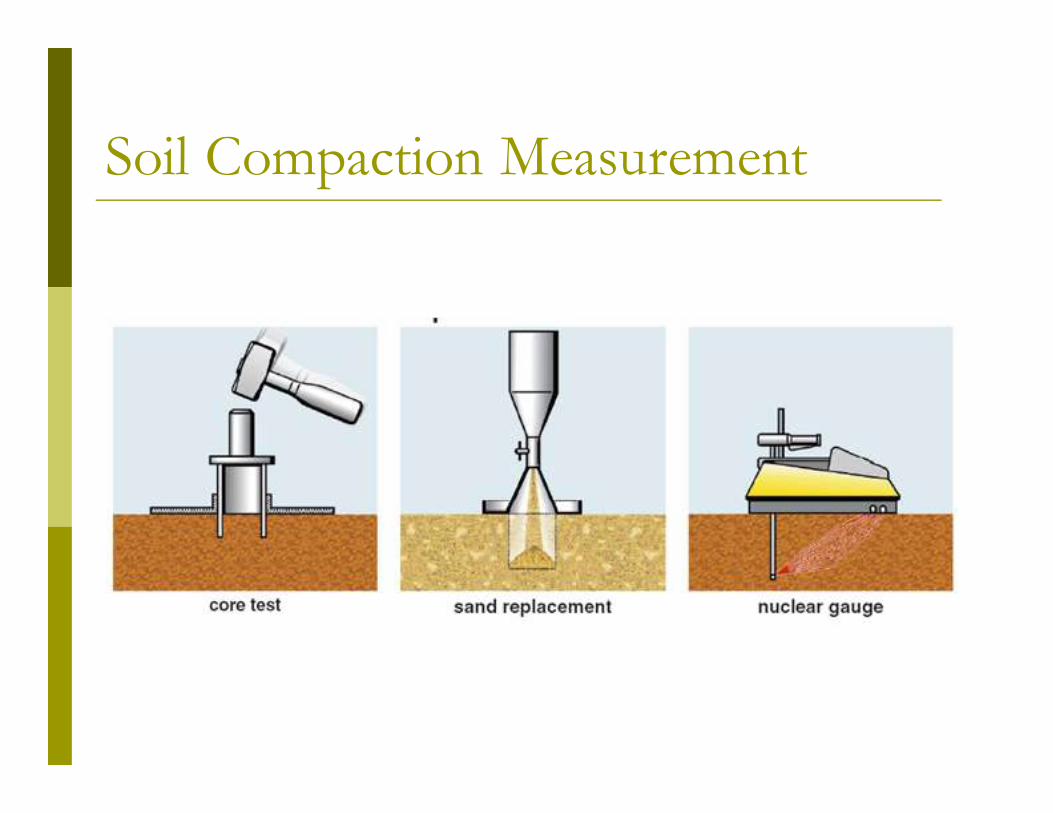
Soil Compaction Measurement
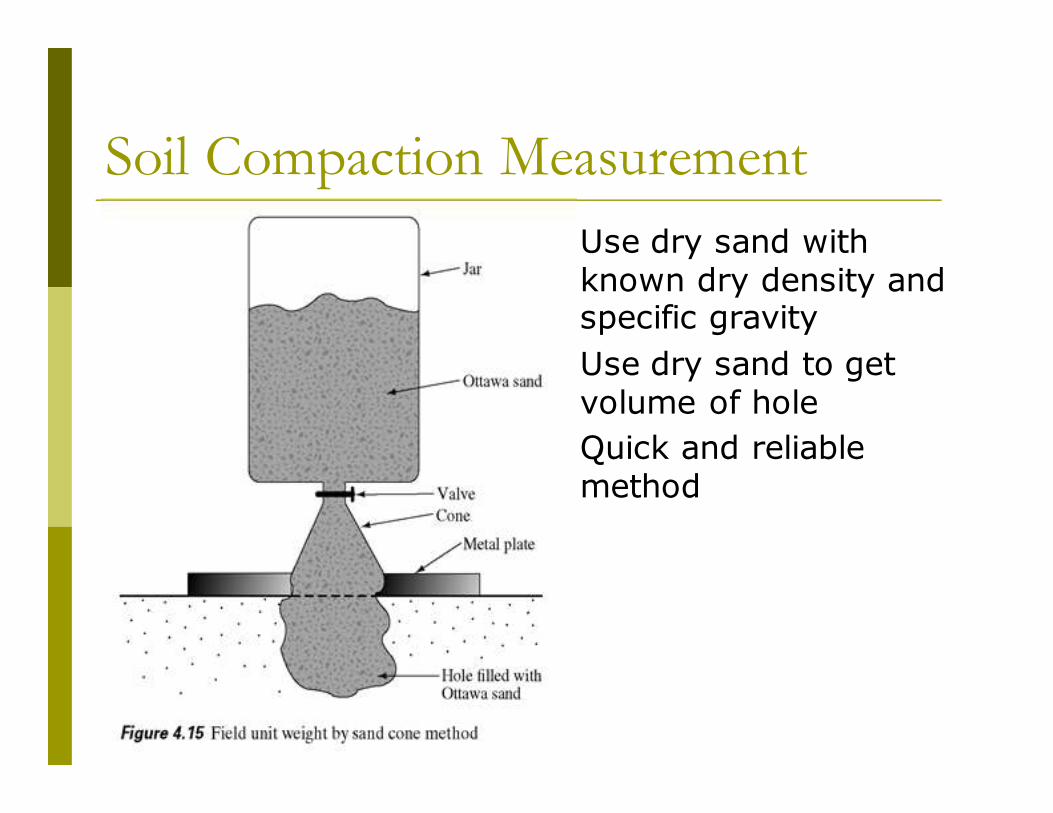
Soil Compaction Measurement
� Use dry sand with known dry density and specific gravity
� Use dry sand to get volume of hole
� Quick and reliable method
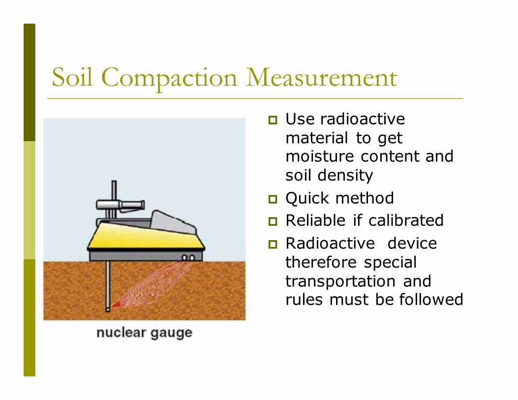
Soil Compaction Measurement
� Use radioactive material to get moisture content and soil density
� Quick method
� Reliable if calibrated
� Radioactive device therefore special transportation and rules must be followed
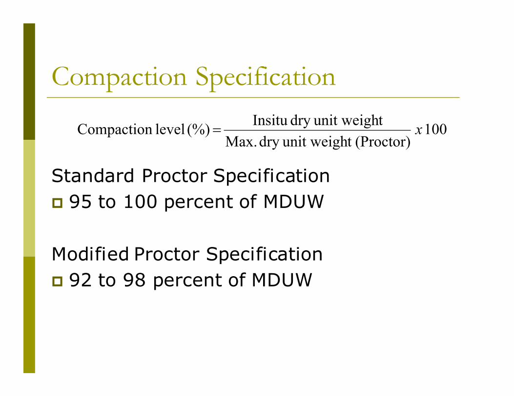
Compaction Specification
Standard Proctor Specification
� 95 to 100 percent of MDUW
Modified Proctor Specification
� 92 to 98 percent of MDUW
100 (Proctor)t unit weighdry Max.
tunit weighdry Insitu (%) level Compaction x=
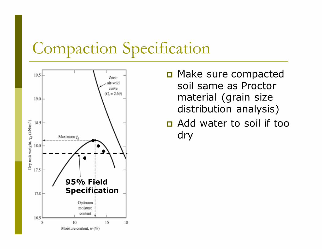
Compaction Specification
� Make sure compacted soil same as Proctor material (grain size distribution analysis)
� Add water to soil if too dry
95% Field Specification
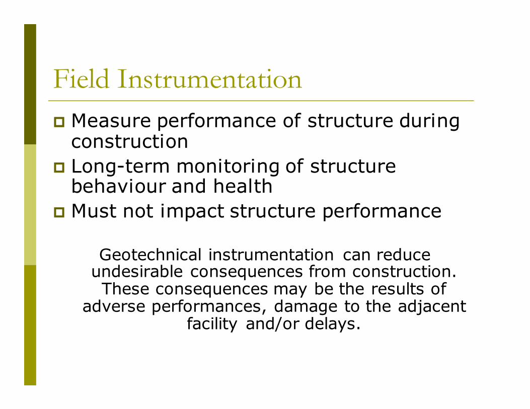
Field Instrumentation
� Measure performance of structure during construction
� Long-term monitoring of structure behaviour and health
� Must not impact structure performance
Geotechnical instrumentation can reduce undesirable consequences from construction. These consequences may be the results of
adverse performances, damage to the adjacent facility and/or delays.
� Engineers should developed justifications for geotechnical instrumentation program on
their projects
� In practice such programs are used to save
lives, save money and/ or reduce risk of
failure
In concept, these are simple and easy to
understand benefits but in practice it is difficult to quantify
Justification for Instrumentation
� Indicate impending failures
� Provide a warning
� Reveal unknowns
� Evaluate critical design assumptions
� Assess contractor's means and methods
� Minimize damage to the adjacent structures
� Control construction
� Control operation
� Provide data to help select remedial methods to fix problems
� Documents performance for assessing damages
� Inform stakeholders
� Satisfy regulators
� Reduce litigation
� Advanced state- of – knowledge
Reasons to Install Instrumentation
Field Instrumentation
� Piezometers � Excess pwp in core during compaction
� Uplift pressures
� Foundation head loss
� Core pheatic surface
� Inclinometers � Stability of slopes and foundations
� Settlement gauges
� Extensometers
� Total earth pressures (soil arching)
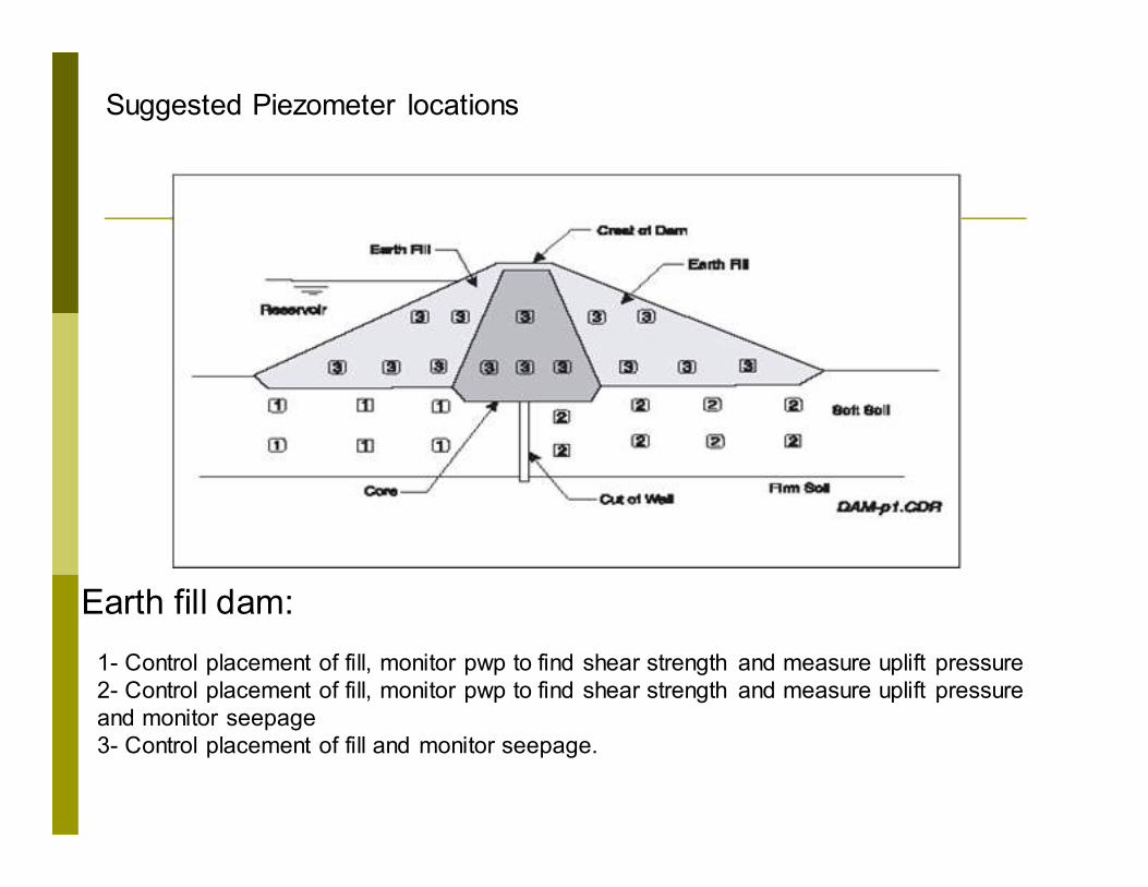
Earth fill dam:
1- Control placement of fill, monitor pwp to find shear strength and measure uplift pressure
2- Control placement of fill, monitor pwp to find shear strength and measure uplift pressure
and monitor seepage
3- Control placement of fill and monitor seepage.
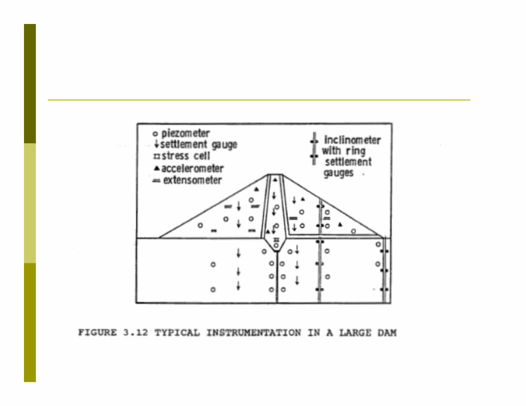
Suggested Piezometer locations
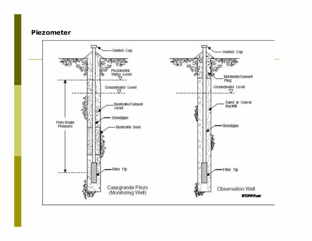
Piezometer
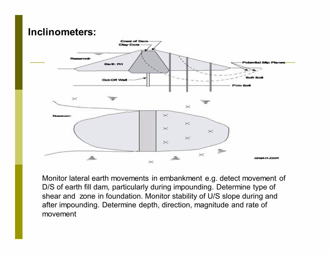
Monitor lateral earth movements in embankment e.g. detect movement of D/S of earth fill dam, particularly during impounding. Determine type of
shear and zone in foundation. Monitor stability of U/S slope during and after impounding. Determine depth, direction, magnitude and rate of
movement
Inclinometers:

Inclinometer
system (Courtesy of N. Sivakugan,
James Cook University, Australia)
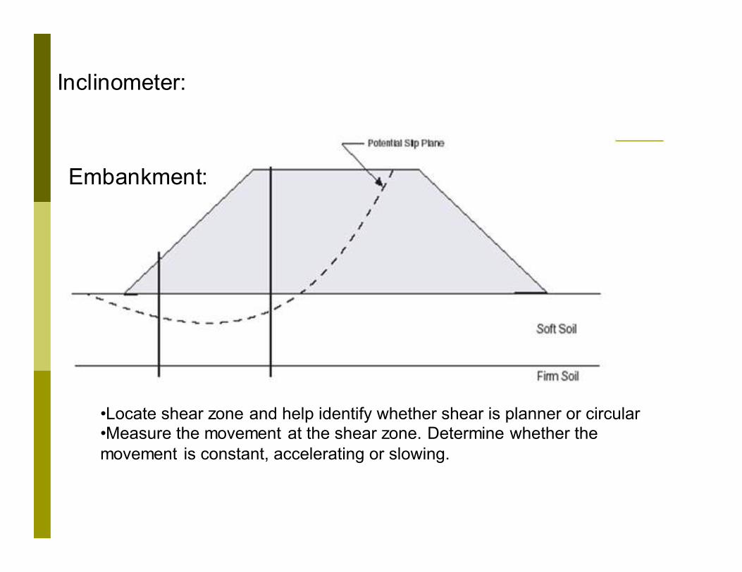
•Locate shear zone and help identify whether shear is planner or circular •Measure the movement at the shear zone. Determine whether the
movement is constant, accelerating or slowing.
Embankment:
Inclinometer:
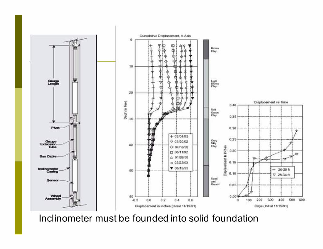
Inclinometer must be founded into solid foundation

5- Tilt meter: Monitor changes in the tilt of the structure. Activities such as dewatering, tunnelling, excavation causes settlement or lateral deformation. Placement of surcharge and pressure may cause heaves. Dam impounding, excavation beyond diaphragm wall etc.
Monitor differential settlement
Dewatering
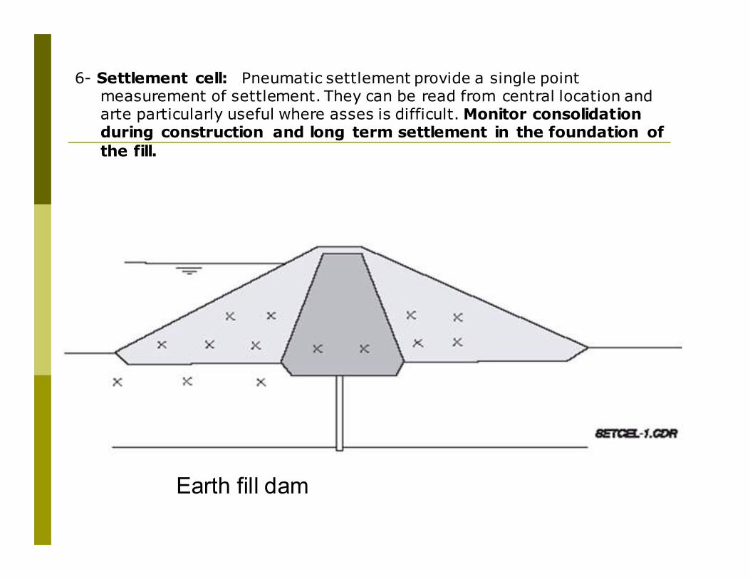
6- Settlement cell: Pneumatic settlement provide a single point measurement of settlement. They can be read from central location and arte particularly useful where asses is difficult. Monitor consolidation during construction and long term settlement in the foundation of
the fill.
Earth fill dam
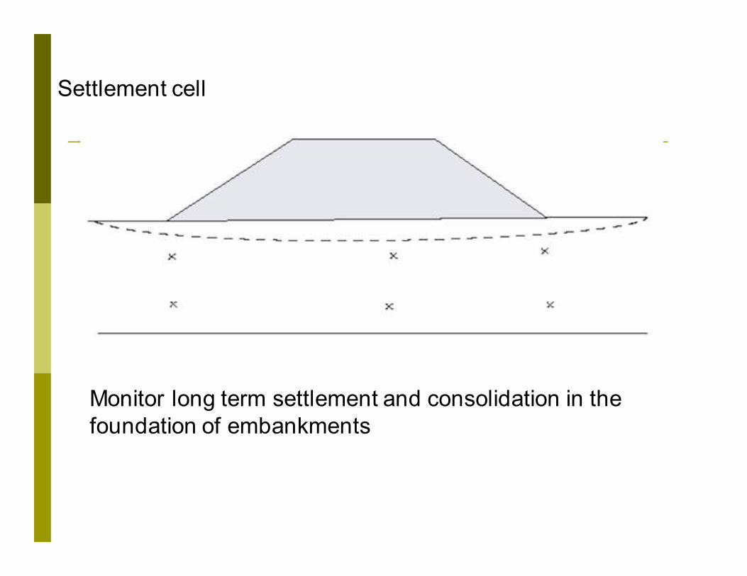
Monitor long term settlement and consolidation in the
foundation of embankments
Settlement cell
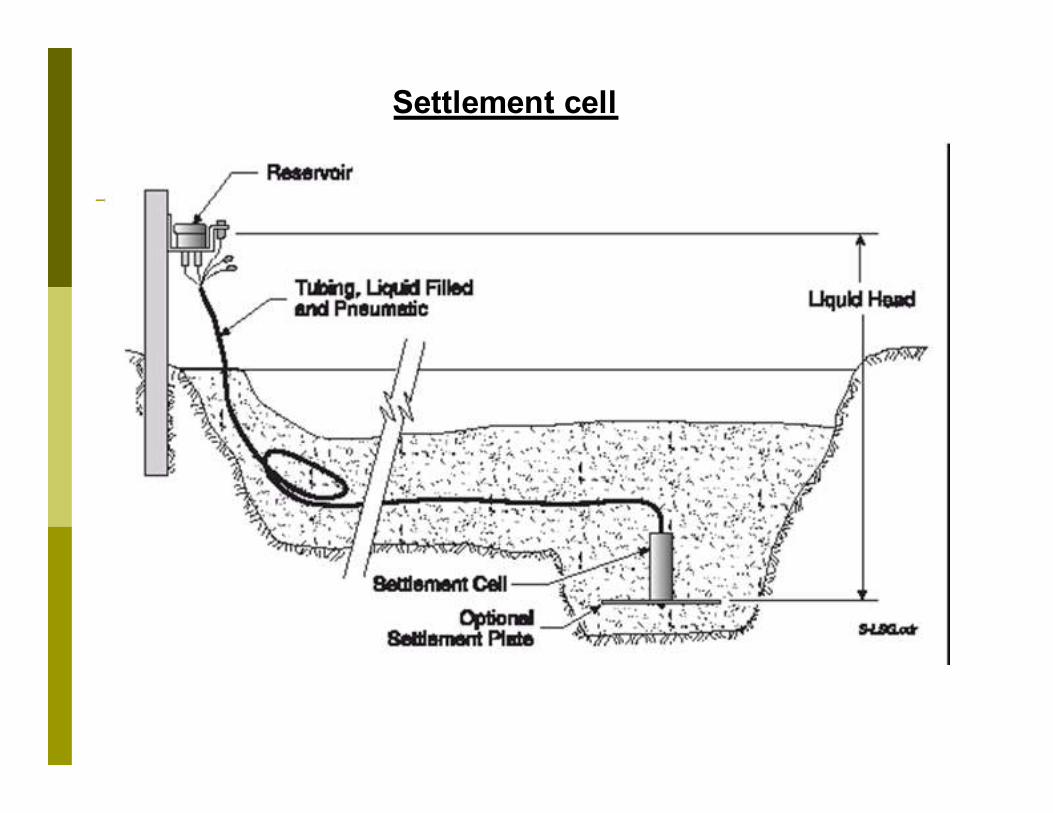
Settlement cell
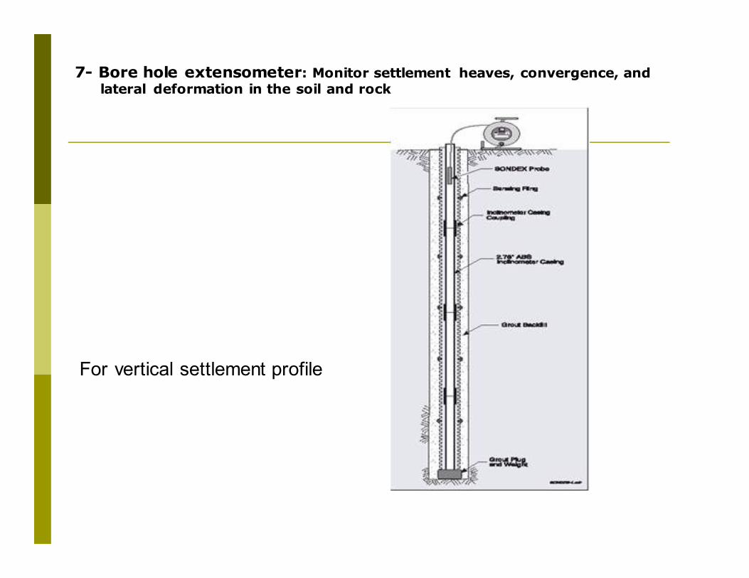
7- Bore hole extensometer: Monitor settlement heaves, convergence, and lateral deformation in the soil and rock
For vertical settlement profile
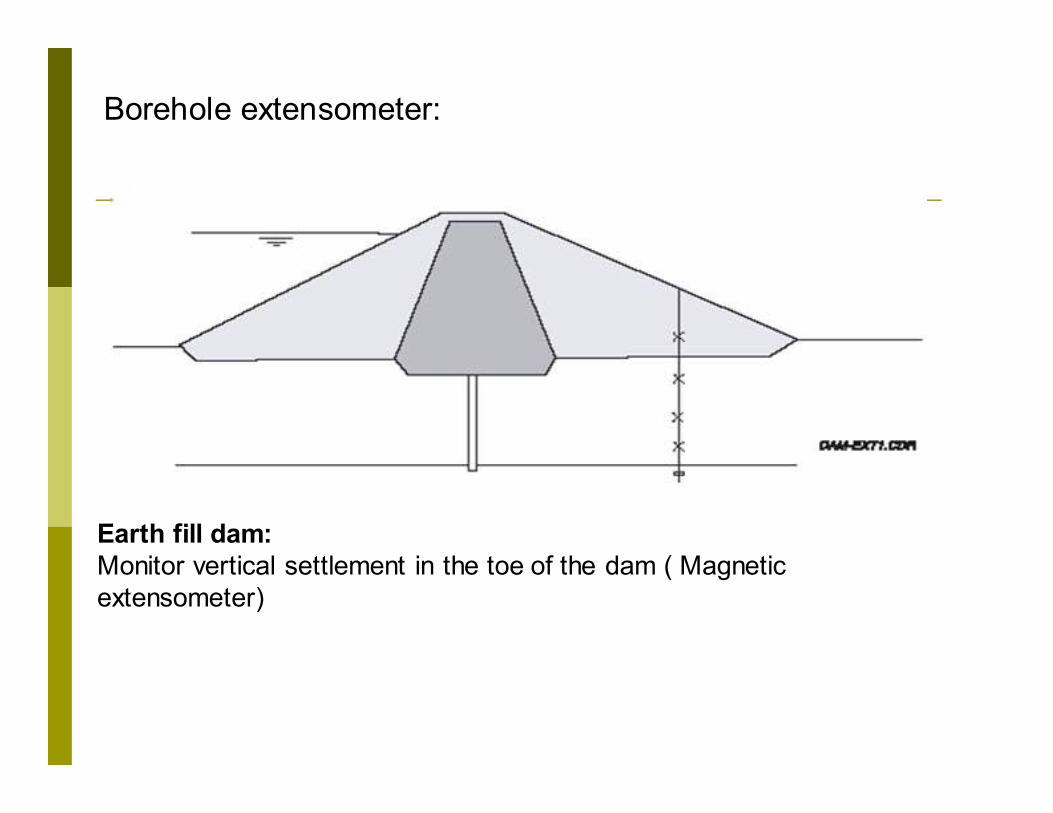
Earth fill dam:
Monitor vertical settlement in the toe of the dam ( Magnetic
extensometer)
Borehole extensometer:
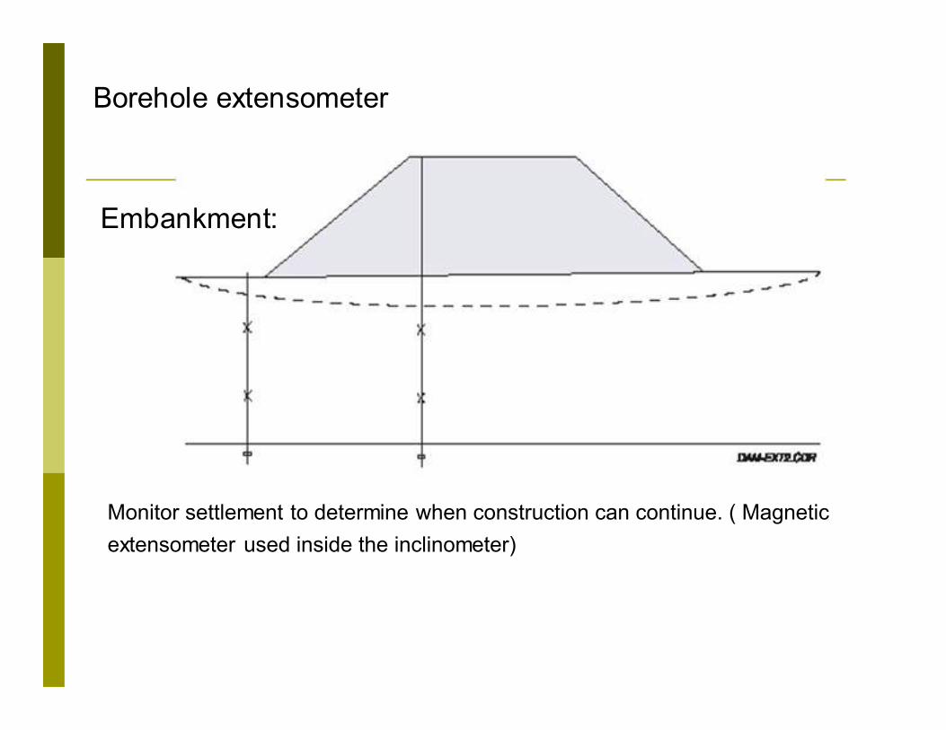
Monitor settlement to determine when construction can continue. ( Magnetic
extensometer used inside the inclinometer)
Embankment:
Borehole extensometer
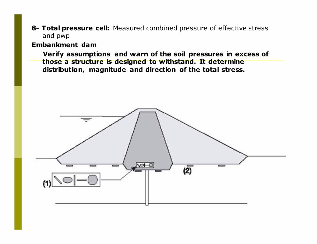
8- Total pressure cell: Measured combined pressure of effective stress and pwp
Embankment dam
Verify assumptions and warn of the soil pressures in excess of those a structure is designed to withstand. It determine
distribution, magnitude and direction of the total stress.

Earth pressure cell (Courtesy of N. Sivakugan, James Cook University, Australia)
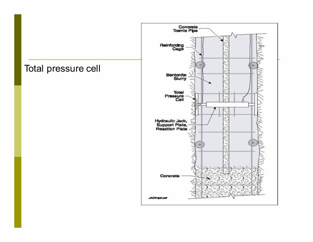
Total pressure cell
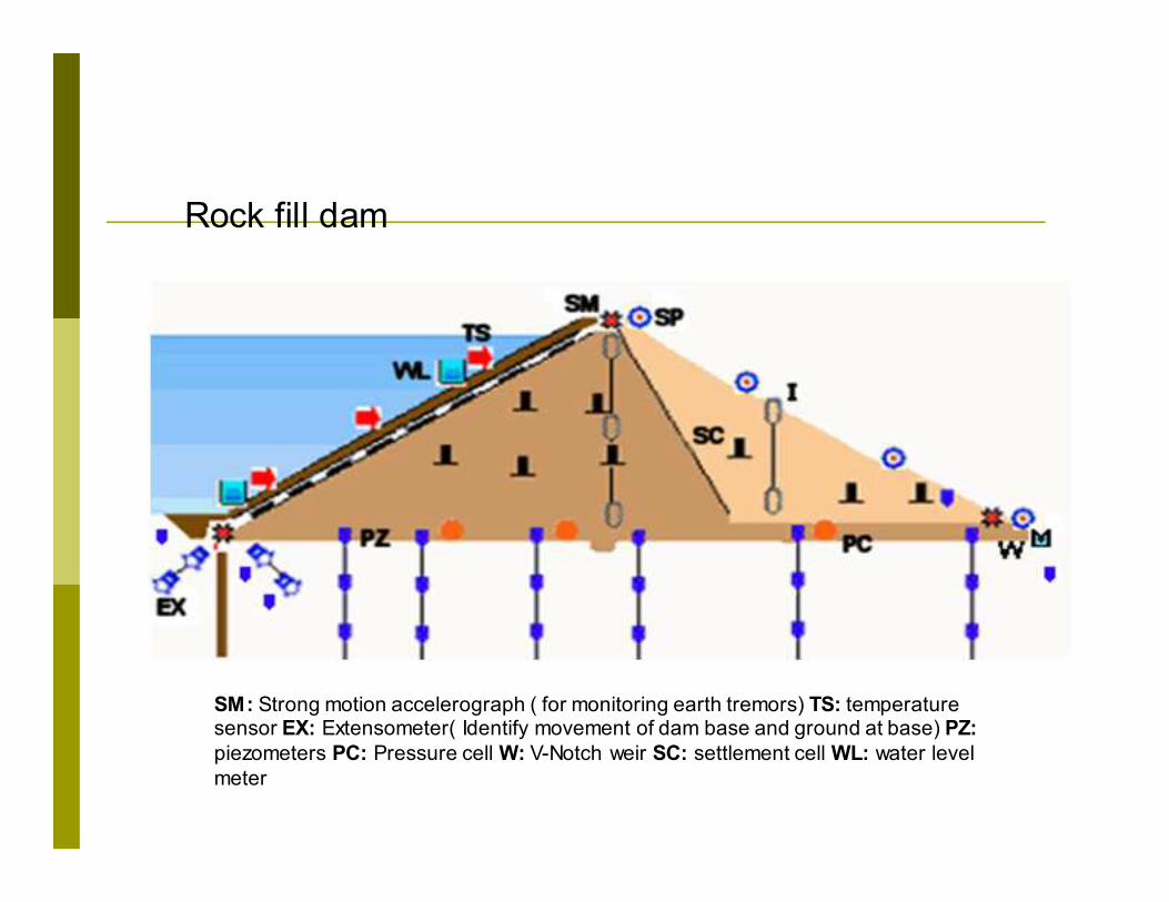
Rock fill dam
SM: Strong motion accelerograph ( for monitoring earth tremors) TS: temperature sensor EX: Extensometer( Identify movement of dam base and ground at base) PZ:
piezometers PC: Pressure cell W: V-Notch weir SC: settlement cell WL: water level
meter
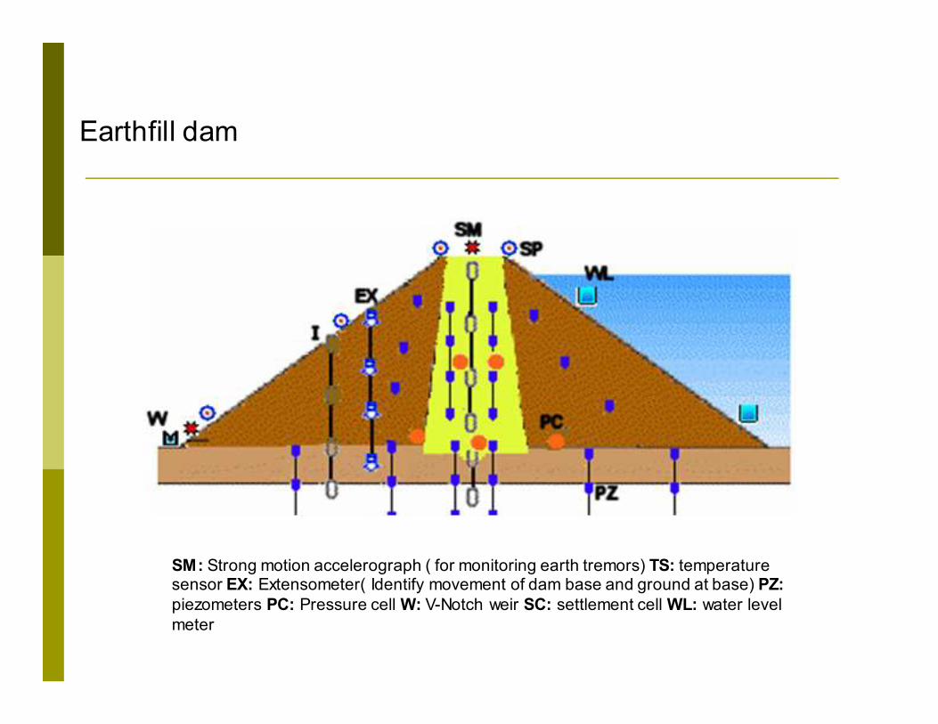
Earthfill dam
SM: Strong motion accelerograph ( for monitoring earth tremors) TS: temperature sensor EX: Extensometer( Identify movement of dam base and ground at base) PZ:
piezometers PC: Pressure cell W: V-Notch weir SC: settlement cell WL: water level
meter
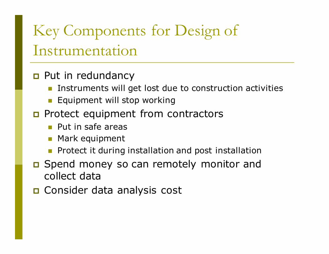
Key Components for Design of
Instrumentation
� Put in redundancy � Instruments will get lost due to construction activities
� Equipment will stop working
� Protect equipment from contractors
� Put in safe areas
� Mark equipment
� Protect it during installation and post installation
� Spend money so can remotely monitor and collect data
� Consider data analysis cost
Key References
Geotechnical Instrumentation for Monitoring Field Performance by John Dunnicliff 1993 Wiley & Sons
Rock Slope Engineering by Hoek & Bray 3rd Edition – Can be downloaded from web. By searching Evert Hoek
US Corps of Engineers- Instrumentation of Embankments Dams and Levees (posted on course website)