Embed Size (px)
Citation preview
Construction of a Prototype Hadronic Calorimeter with Digital Readout
(LCRD)
Calorimetry
Contact person
Joseacute Repond e-mail repondhepanlgov
phone (630)-252-7554
Argonne National Laboratory Boston University
University of Chicago Fermi National Accelerator Laboratory
University of Iowa
FY2006 $105000
Project name Construction of a Prototype Section of a Digital Hadron Calorimeter Classification (acceleratordetectorsubsystem) Detector Institution(s) and personnel Argonne National Laboratory Gary Drake (electronics engineer) Victor Guarino (mechanical engineer) Steve Kuhlmann (staff scientist) Steve Magill (staff scientist) Brian Musgrave (scientist emeritus) Joseacute Repond (staff scientist) Dave Underwood (staff scientist) Harry Weerts (staff scientist) Barry Wicklund (staff scientist) Lei Xia (postdoctoral research associate) Boston University John Butler (professor) Meenakshi Narain (professor) University of Chicago Mark Oreglia (professor) Fermilab Marcel Demarteau (staff scientist) Dmitri Denisov (staff scientist) James Hoff (electronics engineer) Abderrezak Mekkaoui (electronics engineer) Adam Para (staff scientist) Ray Yarema (electronics engineer) University of Iowa Edwin Norbeck (professor) Yasar Onel (professor) Contact person Joseacute Repond repondhepanlgov(630)-252-7554
Project overview We propose to construct a 1 m3 prototype section of a digital hadron calorimeter The section will consist of 40 steel plates each 20 mm thick interleaved with Resistive Plate Chambers (RPCs) as the active medium This project is part of the design of a detector for the International Linear Collider (ILC) At the ILC in order to disentangle W and Z bosons via their hadronic decay into a pair of jets jet energy resolutions of the order of 30radicEjet or better are required Simulation studies have shown that with the help of Particle Flow Algorithms (PFAs) these types of resolutions can be achieved Contrary to conventional methods relying solely on the calorimetric measurements PFAs attempt to measure each final state particle in a jet separately utilizing the detector component able to provide the best momentumenergy resolution So charged particles are measured by the tracking detectors imbedded in a strong magnetic field photons are measured with the electromagnetic calorimeter and neutral hadrons ie neutrons and KL
0 are measured with the electromagnetic and hadronic calorimeters The major challenge of this approach is the separation of energy clusters in the calorimeter originating from charged and neutral particles In order to keep this contribution commonly named the lsquoconfusionrsquo term to the resolution small the readout of the RPCs will be extremely finely segmented 1 cm2 laterally and layer-by-layer longitudinally The optimal segmentation for the ILC detector will be determined after evaluation of the test beam results and the subsequent tuning of the simulation of hadronic showers (see below) The electronic readout will be reduced to a single bit per readout channel (digital readout) Simulation studies have shown that a digital readout of finely segmented pads is able to preserve if not improve the energy resolution of single hadrons traditionally measured with analog readout of calorimeter towers The readout system will be entirely compatible with the readout of Gas Electron Multiplier chambers (GEMs) which are also being considered for digital hadron calorimetry [1] The proposed digital hadron calorimeter (DHCAL) for the ILC is an entirely novel idea which will be substantiated with measurements in test beams at Fermilab The tests will be either in stand-alone mode or together with a prototype of the electromagnetic calorimeter placed in front of the DHCAL The proposed technology of a digital hadron calorimeter with RPCs is equally applicable to all three ILC detector design efforts namely the SiD the LDC and the GDC concepts The major reasons for constructing a prototype section of a DHCAL and subsequent tests in particle beams are summarized in the following This effort is arguably the most important RampD project related to the development of an ILC detector
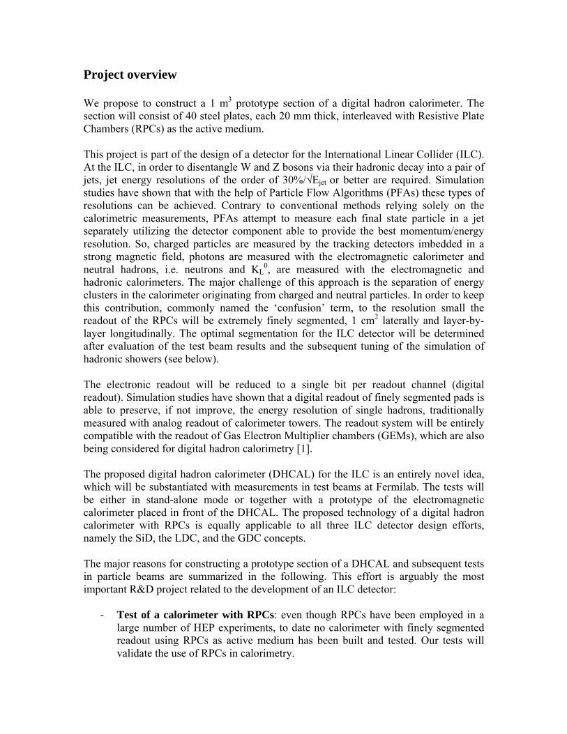
- Test of a calorimeter with RPCs even though RPCs have been employed in a large number of HEP experiments to date no calorimeter with finely segmented readout using RPCs as active medium has been built and tested Our tests will validate the use of RPCs in calorimetry
- Tests of the novel idea of a DHCAL in simulation studies of a DHCAL the resolution obtained for single hadrons is comparable to the results obtained with analog readout Experimental verification of this and validation of the concept of a DHCAL is needed
- Study of design parameters measurements with different configurations of the prototype section will provide a better understanding of the dependence of the response on the various design parameters such as the choice of absorber the size of the active gap the segmentation of the readout etc
- Measurement of hadronic showers traditional calorimeters measure energy with a coarse segmentation thus integrating over large volumes Our DHCAL prototype section will measure hadronic showers with unprecedented spatial resolution and provide very detailed information on hadronic showers
- Validation of Monte Carlo simulation of hadronic showers the measurements obtained in particle beams will be essential to validate the Monte Carlo simulation of hadronic showers To date differences of up to 60 are observed when comparing the results on shower shapes based on different MC models of the hadronic shower see Figure 1 The design of a detector for the International Linear Collider is driven by the application of Particle Flow Algorithms for the measurement of hadronic jets A realistic simulation of hadronic showers is a prerequisite for the development of a reliable design of such a detector
- Comparison with an Analog Hadron Calorimeter Currently the CALICE collaboration [3] is assembling a prototype section of a hadron calorimeter (AHCAL) using scintillator tiles and analog readout The lateral size of the tiles is about a factor of 10 larger than the readout pads of the DHCAL A technology choice for the hadron calorimeter for an ILC detector will be based on a detailed comparison of the performance of the AHCAL and DHCAL prototypes
Figure 1 Comparison of the shower radius in a hadron calorimeter as predicted with fifteen different MC models of the hadronic showers normalized to the result with G4-FTFP
Studies of the performance of a digital hadron calorimeter Detailed Monte Carlo studies based on GEANT4 are being performed to understand the response of calorimeters develop PFAs and to optimize the design of an ILC detector for the measurement of hadronic jets The studies summarized in the following are based on the SiD concept [3] The SiD concept study defined a baseline design for their detector as a starting point for subsequent design studies The baseline design features a six layer vertex detector a five layer silicon tracking detector a Silicon-tungsten electromagnetic calorimeter with 016 cm2 readout cells a RPC-Steel hadronic calorimeter with 1 cm2 readout pads a superconducting coil providing a 5 Tesla fields and an instrumented return yoke The single particle response for 5 GeV π+ is shown in Figure 2 a) using analog readout and b) using 1 cm2 pads with digital readout Digital readout is clearly able to preserve the resolution In addition due to its inherent insensitivity to Landau fluctuations the response measured with digital readout is more symmetric and does not feature a tail towards larger values
Figure 2 Response of a hadron calorimeter to 5 GeV π+ a) with analog readout of scintillator tiles σmicro~ 22 and b) with digital readout of 1 cm2 pads σmicro~ 19 Several groups are involved in the development of PFAs using the SiD baseline design The PFAs contain the following major ingredients clustering of the calorimeter cells track-cluster matching identification of photons identification of neutral hadronic clusters and assignment of cluster fragments to charged or neutral particles First results have been presented at conferences and workshop As an example Figure 3 shows the reconstructed mass obtained in e+e- rarr Z0 rarr 2 jets The central part of the response is fit to a Gaussian with a width of 32 GeV corresponding to approximately σE = 33radicEjet and containing 60 of the events Even though further improvements are necessary to reduce the tails these results demonstrate within the credibility of the simulation of
hadronic showers that jet energies can be measured with a resolution significantly better than the 50 ndash 100radicEjet obtained in calorimetric measurements Figure 3 Reconstructed mass of dijets in e+e- rarr Z0 rarr 2 jets events The width of the central Gaussian is 32 GeV and contains approximately 60 of the events
Description of the 1 m3 Prototype Section General description The planned prototype section features 40 layers each with an area of 1 m2 The physical extend is approximately one meter in depth Simulation studies showed that 98 of the energy of a 10 GeV π+ is contained in the prototype section see Figure 4 for a visual impression of the spatial distribution of the energy deposition of a hadronic shower Figure 4 Average energy deposition from a 10 GeV π+ in the prototype electromagnetic and hadronic calorimeters Mechanical structure The mechanical structure consists of a movable table and the 40 absorber plates The latter are made of stainless steel with a thickness of 16 mm and an area of 1 m2 They are suspended such that the gap between neighboring plates can be adjusted from 05 to 1 cm depending on the thickness of the active elements The table provides all the flexibility of positioning necessary in a test beam such that every cell in the prototype section can be exposed to a muon beam without having to move the beam In addition the table can be rotated along a vertical axis for studies of the response of particles entering the calorimeter at an angle Figure 5 shows the three-dimensional design of the table
The design and construction of the table are the responsibility of DESY in Hamburg Germany
Figure 5 Three-dimensional design of the table for beam tests including stack of absorber plates of the hadron calorimeter Active medium Resistive Plate Chambers (RPCs) with small readout pads are an ideal candidate for a hadron calorimeter designed to optimize the application of PFA They can provide the segmentation of the readout pads of the order of 1 to 4 cm2 which is necessary to keep the lsquoconfusionrsquo term small and they can be built to fit small active gaps (less then 10 mm) to maintain a small lateral shower size Glass RPCs have been found to be stable in operation for long periods of time especially when run in avalanche mode and the rate capabilities are adequate for the ILC and for test beam studies of hadronic showers RPCs are inexpensive to build since most parts are available commercially The readout electronics can be simplified to a one-bit per pad resolution Signals in avalanche mode are large enough to simplify the design of the front-end electronics Figure 6 shows a schematic diagram of a single-gap RPC The chamber consists of two plates with high electrical resistance Readily available window glass of thickness 08 to 11 mm will be used to construct the RPC High voltage is applied to a resistance coating on the outside of the glass plates The resistance of this coating must be low enough to re-charge the glass locally after a signal hit and high enough to allow the electric field of the electron avalanche in the gas to reach the external signal pick-up pads The glass plates enclose a gas volume in which ionization and electron multiplication takes place Particles traversing the gas gap ionize the gas creating an avalanche of electrons drifting towards the glass plate at positive high voltage The signal is picked up inductively with pads located on the outside of the glass
Figure 6 Schematic diagram of a typical Resistive Plate Chamber For the prototype section each layer with an area of 1 m2 will be equipped with three chambers with an area of 32x96 cm2 Each chamber contains 3072 readout pads Since digital hadron calorimetry is a new approach additional beam tests with Gas Electron Multiplier chambers (GEMs) replacing some layers of RPCs in the prototype section are planned Differences in pad-to-pad cross talk rate capability operational stability etc will be studied The electronic readout system is designed such that both RPCs and GEMs can be read out with the same front-end and back-end system Electronic readout system Considerable effort is dedicated to the development of the electronic readout system a challenge by itself given the large number of channels of order 4 10times 5 for the prototype section and 5 10times 7 for the DHCAL of an ILC detector The readout electronics is suitable for both the RPC and the GEM readout The gain of the front-end is adjustable to accommodate the different signal sizes of the two devices Particular care was devoted to keeping the cost per channel as small as possible The electronic readout system consists of several stages a) the front-end ASIC b) the front-end boards c) the data concentrator d) the super concentrators e) a VME-based data collector and e) a trigger and timing system In the following we briefly describe the individual stages
a) The front-end ASIC receives signals from 64 individual pads The signals are shaped amplified and discriminated The resulting hit patterns are time stamped and stored at a speed of 10 MHz In triggered mode an external trigger selects the events to be passed on to the data concentrator In triggerless mode any hit pattern with at least one hit will be written out The ASICs will be located directly on the PC boards containing the readout pads of the chambers
b) The front-end boards are located directly on the chambers Two boards with dimensions of 32x48 cm2 are required per chamber The boards contain the readout pad and transfer lines to the ASIC (analog signals) as well as the path for the digital output signals from the ASIC Special care is necessary for proper
Signal
Graphite
Resistive plates
Pick-up pads
HV
Gas
shielding of the analog circuitry from digital noise The boards contain 8 ndash 10 layers
c) The data concentrators receive data from 12 individual ASICs They mainly consist of FPGAs and will be located on the side of the 1 m3 prototype section of the hadronic calorimeter
d) The super concentrator further multiplexes the readout by reading out six data concentrators Their design is similar to the data concentrators
e) The data collector is VMEndashbased and receives the output of the super concentrators Each card will connect to 12 individual data concentrators The system specifications are very similar to the recently developed system for the MINOS test beam effort
f) The trigger system distributes the trigger information to the data concentrators The timing system provides the clocks and clock resets of the readout system
Planned measurements in the Fermilab test beam We plan to expose the prototype DHCAL section to the MTB6 test beam at Fermilab The calorimeter will be tested both in standalone mode as well as in combination with a prototype electromagnetic calorimeter located in front The latter will be provided initially by the CALICE collaboration [3] and later by the SLAC-Oregon group [4] A tail-catcher [5] consisting of steel plates and scintillator strips will be placed behind the DHCAL prototype In the following we briefly describe the planned test beam activities Standalone tests of the DHCAL prototype including the tail catcher Standalone tests of the prototype section of the DHCAL will be performed in the following configurations Energy Scans with Pions and Protons Single pion responses linearity and energy resolution will be measured using a wide range of momenta (from 1 GeVc up to 66 GeVc) The response to protons over the entire momentum range (up to 120 GeVc) will be measured as well Incident Angle Scans Measurements with at least three different angles of incidence will be performed The angles will be changed by rotating the table with respect to the beam and off-setting the calorimeter structure in depth in order to optimize the lateral containment These tests are foreseen using at least two different energy settings Muon Responses Measurements with momentum tagged (3 ndash 20 GeVc) muons will be performed for muon detection efficiency measurement testing reconstruction codes and developing calorimeter tracking algorithms Calibration Runs For calibration purposes measurements with defocused muons will be performed at regular intervals during the testing period Combined tests of electromagnetic and hadronic calorimeters including tail catchers The following test program is foreseen for the combination of ECAL and DHCAL prototypes Electron Energy Scans These tests require electrons with the highest achievable energy to provide a data set with combined ECAL and DHCAL information Energy Scans with Pions and Protons Single pion responses linearity and energy resolution will be measured using a wide range of momenta (1 ndash 66 GeVc) The response to protons over the entire momentum range (up to 120 GeVc) will be measured as well
Incident Angle Scans Measurements with at least three different angles of incidence will be performed These tests are foreseen using at least two different energy settings Muon Responses Measurements with momentum tagged (3 ndash 20 GeVc) muons will be performed for testing MIP reconstruction codes and developing calorimeter tracking algorithms Calibration Runs For calibration purposes measurements with defocused muons will be performed at regular intervals during the testing period These tests will start in 2007 and last until approximately the end of 2008 The CALICE collaboration plans to use the same beam line for measurements with their electromagnetic and analog hadron calorimeter prototypes Comparison of the results of the analog and digital hadron calorimeters using the same beam line (and absorber configuration) will be essential for deciding on the technology to be used for the ILC detectorrsquos hadron calorimeter Recently Fermilab reviewed [6] the feasibility of modifications to the MTBF beam line as requested by the CALICE collaboration The decision was taken to move the target for the production of secondary particles closer to the experimental area thus increasing the rate of low energy pions by several orders of magnitude
Current status of the project RampD on Resistive Plate Chambers Work on developing RPCs for application in a hadron calorimeter has been underway for the past two to three years at Argonne National Laboratory A number of single- and multi-gap chambers have been built and have been tested thoroughly with sources and cosmic rays The chambers vary in design containing one to three glass plates and resistive coats of different surface resistivity Table I lists the different measurements performed on the chambers For more details see [7]
Measurement Status Signal characterization Completed HV dependence Completed Single pad efficiencies Completed Geometrical efficiencies Completed Tests with different gases Completed Mechanical properties Completed Multipad efficiencies Completed Hit multiplicities Completed Noise rates Completed Rate capability (source and cosmics) Completed Tests in 5 T magnetic field Completed by other groups Tests in particle beams Planned Long term tests Ongoing Design of larger chamber Ongoing
Table I List of measurements performed on the ANL prototype RPCs As an example of the measurements performed with the prototype chambers Figure 7 shows the hit multiplicity versus detection efficiency for chambers operating at different high voltages Based on these tests we have developed a base design of RPCs for the digital hadron calorimeter We are confident that these chambers will perform as required for the prototype beam tests RampD on the electronic readout system A conceptual design of the electronic readout system for the prototype section has been developed and documented [8] The ASICs have been designed by Fermilab in collaboration with ANL A first prototype run is currently being evaluated A computer controlled test board has been designed and fabricated see Figure 8 Several changes to the analog part of the circuitry are planned
requiring a second iteration before production of the required 8000 chips for the prototype section can be envisaged
Figure 7 Multiplicity as a function of single particle detection efficiency for a RPC operated at three different high voltage settings Computer
interface DCAL Figure 8 Photograph of DCAL test boards board containing DCAL chip (left) and computer interface board (right)
A prototype of the Front-end board has been fabricated The board is designed specifically for the study of the cross-talk between digital (LVDS signals) and analog signals The measurements indicate a small cross-talk of the order of 10 ndash 20 fC which is within the range of acceptable values for operation with RPCs Due to the significantly smaller signal size of the order of a factor of 10 further reductions of the cross-talk are necessary for the readout of GEMs Design work on the data concentrators and the VME-based data collector has initiated The possibility of using the data collector system (CRC-boards) of the analog hadron calorimeter prototype is being investigated Preparation for the test beam Discussions with the management of Fermilab and the people responsible for the test beam have initiated some time ago A detailed technical note [9] written by the worldwide ILC calorimeter test beam group was submitted to Fermilab in February 2005 The note details the goals and requirements of the test beam program As a further step towards a test beam program at Fermilab the ANL and University of Iowa groups are planning on testing single layers of RPCs in the MTBF test beam These tests will be particular useful in determining the particle rates for pions as a function of energy The groups plan to perform measurements of the single particle detection efficiency as a function of incident particle rates A Memorandum of Understanding between ANL University of Iowa and Fermilab is in preparation The tests are planned for early 2006
Construction of the 1 m3 prototype section Construction of RPCs To fully equip the 1m3 prototype section a total of 120 RPCs are necessary The chambers will be mounted on a strong ndash back a 4 mm copper plate The perimeter of the strong ndash back will be equipped with cooling tubes to cool the heat generated by the ASICs located on the front-end boards A quality assurance procedure to ensure the high quality of the chambers and uniform response will be devised The procedure will include tests of the gas tightness as well as measurements of the single particle detection efficiency Construction of the electronic readout system Table II lists the different parts of the readout system and the number of units needed to fully equip the prototype section Each unit will be thoroughly tested in computer controlled test fixtures
Component chamber plane channelsunit Total units Planes 0333 1 9216 40 Chambers 1 3 3072 120 DCAL ASICs 24 144 64 5760 Front-end boards 2 6 1536 240 Data concentrators 4 12 768 480 Super concentrators 0667 2 4608 80 Data collectors - 0166 55296 7 VME crates - - 387072 1
Table II List of the parts of the electronic readout system
Responsibilities as assigned to institutions participating in the project Table III summarizes the responsibilities as assigned to the different institutions participating in the project Argonne National Laboratory Construction of chambers
Overall electronic system design Test fixtures for front-end ASIC VME based data collector system Transportation of RPCs to test beam
Boston VME based data collector system Chicago Data concentrator boards DESY Mechanical structure FNAL Front-end ASICs
Front-end readout boards
Iowa High voltage distribution system Gas distribution system
UTA Timing and triggering system not part of this proposal Table III Responsibility for the construction and testing of the various subsystems of the prototype DHCAL section
Budget and budget justification Table IV summarizes the projected MampS costs for the construction of the prototype section
Item Cost Contingency TotalRPC mechanics 32200 9500 41700DCAL ASIC 240000 11600 251600Front-end boards 110000 55000 165000Data concentrators 106000 53000 159000Super concentrators 25000 12500 37500VME data collectors 46500 19250 65750Timing system 20000 10000 30000Power supplies 20000 10000 30000Cables 27500 13750 41250Total 627200 194600 811800
Table IV Summary of the MampS costs for the prototype section The following comments regarding the costs in Table III need to be made
- The costs for the RPC mechanics include a gas distribution system - The cost for the DCAL ASIC includes a second prototype run - The power supplies include both low and high voltage power supplies
Table V summarizes the expected labor costs based on the current rates at ANL and FNAL
Item Cost Contingency TotalMechanical assembly 87600 21900 109500DCAL ASIC 16200 8100 24300Front-end boards 31625 15800 47425Data concentrators 60950 30475 91425Super concentrators 11500 5750 17250VME data collector 35200 17600 52800Total 243075 99625 342700
Table V Summary of labor costs based on current labor rates at ANL and FNAL The total cost of project including labor MampS and contingency is $1164500 The cost of the mechanical structure and beam test table is not included in this estimate since it will be provided by the DESY laboratory Table VI lists the financial contributions expected from participating institutes and others
Institution Contribution Base amount Contingency TotalArgonne and participating institutes
Labor for assembly and testing
226875 91538 318413
Fermilab ASIC production and testing
264200 19700 283900
Total 491075 111238 602313 Table VI Summary of the financial contributions from participating institutions and others Argonnersquos contribution will be to provide the labor for assembling the RPCs and to check-out the different parts of the electronic readout system The participating universities will provide the labor to check out the electronic components for which they have assumed responsibilities see Table VI Table VII finally lists the amounts still to be funded over the period of the next two years Base amount Contingency TotalTotal cost 870275 294225 1164500Contributions 491075 111238 602313Outstanding amount 379200 182987 562187 Table VIII Summary of funds still needed for the construction of the prototype DHCAL section We realize that the outstanding amount of about $400000 (excluding contingencies) can not be funded entirely out of LCRD funds The possibility of receiving funding through supplemental proposals to the DOE is being explored The current proposal therefore requests funding of the order of $105000 through the LCRD funds which is commensurate with the overall size of the LCRD funds Broader Impact The challenges raised by the linear collider physics program promote the development of new detector technologies The necessary fine granularity of the hadron calorimeter requires a novel technical approach The proposed digital hadron calorimeter with Resistive Plate Chambers as active medium fulfills the physics criteria but has never been built and tested before These technological challenges require close collaboration between industries universities and national laboratories The project involves a number of graduate and undergraduate students associated with the universities participating in this proposal At Argonne the project will attract participation from high school teachers and summer students
The detailed measurements of the response to single particles will further the understanding of hadronic showers and provide a unique data base for comparison with simulation The results from this program will be disseminated through national and international conferences and workshops and published in peer-reviewed journals
References [1] LCRD proposal by A White et al [2] httppolywwwin2p3frflccalicehtml[3] httpwww-sidslacstanfordedu[4] httpwwwslacstanfordeduxorglcdSiWSiWhtml[5] httpnicaddniueduresearchlcd[6] httpwww-ppdfnalgovmtbf-wMeetingsmtbf_meetingshtm[7] httpwwwhepanlgovrepondDHCAL_UShtml[8] httpwwwhepanlgovreponddcal_sys_desc_113doc[9] httpwwwhepanlgovrepondFNAL-TM-2291-finaldoc
Project name Construction of a Prototype Section of a Digital Hadron Calorimeter Classification (acceleratordetectorsubsystem) Detector Institution(s) and personnel Argonne National Laboratory Gary Drake (electronics engineer) Victor Guarino (mechanical engineer) Steve Kuhlmann (staff scientist) Steve Magill (staff scientist) Brian Musgrave (scientist emeritus) Joseacute Repond (staff scientist) Dave Underwood (staff scientist) Harry Weerts (staff scientist) Barry Wicklund (staff scientist) Lei Xia (postdoctoral research associate) Boston University John Butler (professor) Meenakshi Narain (professor) University of Chicago Mark Oreglia (professor) Fermilab Marcel Demarteau (staff scientist) Dmitri Denisov (staff scientist) James Hoff (electronics engineer) Abderrezak Mekkaoui (electronics engineer) Adam Para (staff scientist) Ray Yarema (electronics engineer) University of Iowa Edwin Norbeck (professor) Yasar Onel (professor) Contact person Joseacute Repond repondhepanlgov(630)-252-7554
Project overview We propose to construct a 1 m3 prototype section of a digital hadron calorimeter The section will consist of 40 steel plates each 20 mm thick interleaved with Resistive Plate Chambers (RPCs) as the active medium This project is part of the design of a detector for the International Linear Collider (ILC) At the ILC in order to disentangle W and Z bosons via their hadronic decay into a pair of jets jet energy resolutions of the order of 30radicEjet or better are required Simulation studies have shown that with the help of Particle Flow Algorithms (PFAs) these types of resolutions can be achieved Contrary to conventional methods relying solely on the calorimetric measurements PFAs attempt to measure each final state particle in a jet separately utilizing the detector component able to provide the best momentumenergy resolution So charged particles are measured by the tracking detectors imbedded in a strong magnetic field photons are measured with the electromagnetic calorimeter and neutral hadrons ie neutrons and KL
0 are measured with the electromagnetic and hadronic calorimeters The major challenge of this approach is the separation of energy clusters in the calorimeter originating from charged and neutral particles In order to keep this contribution commonly named the lsquoconfusionrsquo term to the resolution small the readout of the RPCs will be extremely finely segmented 1 cm2 laterally and layer-by-layer longitudinally The optimal segmentation for the ILC detector will be determined after evaluation of the test beam results and the subsequent tuning of the simulation of hadronic showers (see below) The electronic readout will be reduced to a single bit per readout channel (digital readout) Simulation studies have shown that a digital readout of finely segmented pads is able to preserve if not improve the energy resolution of single hadrons traditionally measured with analog readout of calorimeter towers The readout system will be entirely compatible with the readout of Gas Electron Multiplier chambers (GEMs) which are also being considered for digital hadron calorimetry [1] The proposed digital hadron calorimeter (DHCAL) for the ILC is an entirely novel idea which will be substantiated with measurements in test beams at Fermilab The tests will be either in stand-alone mode or together with a prototype of the electromagnetic calorimeter placed in front of the DHCAL The proposed technology of a digital hadron calorimeter with RPCs is equally applicable to all three ILC detector design efforts namely the SiD the LDC and the GDC concepts The major reasons for constructing a prototype section of a DHCAL and subsequent tests in particle beams are summarized in the following This effort is arguably the most important RampD project related to the development of an ILC detector
- Test of a calorimeter with RPCs even though RPCs have been employed in a large number of HEP experiments to date no calorimeter with finely segmented readout using RPCs as active medium has been built and tested Our tests will validate the use of RPCs in calorimetry
- Tests of the novel idea of a DHCAL in simulation studies of a DHCAL the resolution obtained for single hadrons is comparable to the results obtained with analog readout Experimental verification of this and validation of the concept of a DHCAL is needed
- Study of design parameters measurements with different configurations of the prototype section will provide a better understanding of the dependence of the response on the various design parameters such as the choice of absorber the size of the active gap the segmentation of the readout etc
- Measurement of hadronic showers traditional calorimeters measure energy with a coarse segmentation thus integrating over large volumes Our DHCAL prototype section will measure hadronic showers with unprecedented spatial resolution and provide very detailed information on hadronic showers
- Validation of Monte Carlo simulation of hadronic showers the measurements obtained in particle beams will be essential to validate the Monte Carlo simulation of hadronic showers To date differences of up to 60 are observed when comparing the results on shower shapes based on different MC models of the hadronic shower see Figure 1 The design of a detector for the International Linear Collider is driven by the application of Particle Flow Algorithms for the measurement of hadronic jets A realistic simulation of hadronic showers is a prerequisite for the development of a reliable design of such a detector
- Comparison with an Analog Hadron Calorimeter Currently the CALICE collaboration [3] is assembling a prototype section of a hadron calorimeter (AHCAL) using scintillator tiles and analog readout The lateral size of the tiles is about a factor of 10 larger than the readout pads of the DHCAL A technology choice for the hadron calorimeter for an ILC detector will be based on a detailed comparison of the performance of the AHCAL and DHCAL prototypes
Figure 1 Comparison of the shower radius in a hadron calorimeter as predicted with fifteen different MC models of the hadronic showers normalized to the result with G4-FTFP
Studies of the performance of a digital hadron calorimeter Detailed Monte Carlo studies based on GEANT4 are being performed to understand the response of calorimeters develop PFAs and to optimize the design of an ILC detector for the measurement of hadronic jets The studies summarized in the following are based on the SiD concept [3] The SiD concept study defined a baseline design for their detector as a starting point for subsequent design studies The baseline design features a six layer vertex detector a five layer silicon tracking detector a Silicon-tungsten electromagnetic calorimeter with 016 cm2 readout cells a RPC-Steel hadronic calorimeter with 1 cm2 readout pads a superconducting coil providing a 5 Tesla fields and an instrumented return yoke The single particle response for 5 GeV π+ is shown in Figure 2 a) using analog readout and b) using 1 cm2 pads with digital readout Digital readout is clearly able to preserve the resolution In addition due to its inherent insensitivity to Landau fluctuations the response measured with digital readout is more symmetric and does not feature a tail towards larger values
Figure 2 Response of a hadron calorimeter to 5 GeV π+ a) with analog readout of scintillator tiles σmicro~ 22 and b) with digital readout of 1 cm2 pads σmicro~ 19 Several groups are involved in the development of PFAs using the SiD baseline design The PFAs contain the following major ingredients clustering of the calorimeter cells track-cluster matching identification of photons identification of neutral hadronic clusters and assignment of cluster fragments to charged or neutral particles First results have been presented at conferences and workshop As an example Figure 3 shows the reconstructed mass obtained in e+e- rarr Z0 rarr 2 jets The central part of the response is fit to a Gaussian with a width of 32 GeV corresponding to approximately σE = 33radicEjet and containing 60 of the events Even though further improvements are necessary to reduce the tails these results demonstrate within the credibility of the simulation of
hadronic showers that jet energies can be measured with a resolution significantly better than the 50 ndash 100radicEjet obtained in calorimetric measurements Figure 3 Reconstructed mass of dijets in e+e- rarr Z0 rarr 2 jets events The width of the central Gaussian is 32 GeV and contains approximately 60 of the events
Description of the 1 m3 Prototype Section General description The planned prototype section features 40 layers each with an area of 1 m2 The physical extend is approximately one meter in depth Simulation studies showed that 98 of the energy of a 10 GeV π+ is contained in the prototype section see Figure 4 for a visual impression of the spatial distribution of the energy deposition of a hadronic shower Figure 4 Average energy deposition from a 10 GeV π+ in the prototype electromagnetic and hadronic calorimeters Mechanical structure The mechanical structure consists of a movable table and the 40 absorber plates The latter are made of stainless steel with a thickness of 16 mm and an area of 1 m2 They are suspended such that the gap between neighboring plates can be adjusted from 05 to 1 cm depending on the thickness of the active elements The table provides all the flexibility of positioning necessary in a test beam such that every cell in the prototype section can be exposed to a muon beam without having to move the beam In addition the table can be rotated along a vertical axis for studies of the response of particles entering the calorimeter at an angle Figure 5 shows the three-dimensional design of the table
The design and construction of the table are the responsibility of DESY in Hamburg Germany
Figure 5 Three-dimensional design of the table for beam tests including stack of absorber plates of the hadron calorimeter Active medium Resistive Plate Chambers (RPCs) with small readout pads are an ideal candidate for a hadron calorimeter designed to optimize the application of PFA They can provide the segmentation of the readout pads of the order of 1 to 4 cm2 which is necessary to keep the lsquoconfusionrsquo term small and they can be built to fit small active gaps (less then 10 mm) to maintain a small lateral shower size Glass RPCs have been found to be stable in operation for long periods of time especially when run in avalanche mode and the rate capabilities are adequate for the ILC and for test beam studies of hadronic showers RPCs are inexpensive to build since most parts are available commercially The readout electronics can be simplified to a one-bit per pad resolution Signals in avalanche mode are large enough to simplify the design of the front-end electronics Figure 6 shows a schematic diagram of a single-gap RPC The chamber consists of two plates with high electrical resistance Readily available window glass of thickness 08 to 11 mm will be used to construct the RPC High voltage is applied to a resistance coating on the outside of the glass plates The resistance of this coating must be low enough to re-charge the glass locally after a signal hit and high enough to allow the electric field of the electron avalanche in the gas to reach the external signal pick-up pads The glass plates enclose a gas volume in which ionization and electron multiplication takes place Particles traversing the gas gap ionize the gas creating an avalanche of electrons drifting towards the glass plate at positive high voltage The signal is picked up inductively with pads located on the outside of the glass
Figure 6 Schematic diagram of a typical Resistive Plate Chamber For the prototype section each layer with an area of 1 m2 will be equipped with three chambers with an area of 32x96 cm2 Each chamber contains 3072 readout pads Since digital hadron calorimetry is a new approach additional beam tests with Gas Electron Multiplier chambers (GEMs) replacing some layers of RPCs in the prototype section are planned Differences in pad-to-pad cross talk rate capability operational stability etc will be studied The electronic readout system is designed such that both RPCs and GEMs can be read out with the same front-end and back-end system Electronic readout system Considerable effort is dedicated to the development of the electronic readout system a challenge by itself given the large number of channels of order 4 10times 5 for the prototype section and 5 10times 7 for the DHCAL of an ILC detector The readout electronics is suitable for both the RPC and the GEM readout The gain of the front-end is adjustable to accommodate the different signal sizes of the two devices Particular care was devoted to keeping the cost per channel as small as possible The electronic readout system consists of several stages a) the front-end ASIC b) the front-end boards c) the data concentrator d) the super concentrators e) a VME-based data collector and e) a trigger and timing system In the following we briefly describe the individual stages
a) The front-end ASIC receives signals from 64 individual pads The signals are shaped amplified and discriminated The resulting hit patterns are time stamped and stored at a speed of 10 MHz In triggered mode an external trigger selects the events to be passed on to the data concentrator In triggerless mode any hit pattern with at least one hit will be written out The ASICs will be located directly on the PC boards containing the readout pads of the chambers
b) The front-end boards are located directly on the chambers Two boards with dimensions of 32x48 cm2 are required per chamber The boards contain the readout pad and transfer lines to the ASIC (analog signals) as well as the path for the digital output signals from the ASIC Special care is necessary for proper
Signal
Graphite
Resistive plates
Pick-up pads
HV
Gas
shielding of the analog circuitry from digital noise The boards contain 8 ndash 10 layers
c) The data concentrators receive data from 12 individual ASICs They mainly consist of FPGAs and will be located on the side of the 1 m3 prototype section of the hadronic calorimeter
d) The super concentrator further multiplexes the readout by reading out six data concentrators Their design is similar to the data concentrators
e) The data collector is VMEndashbased and receives the output of the super concentrators Each card will connect to 12 individual data concentrators The system specifications are very similar to the recently developed system for the MINOS test beam effort
f) The trigger system distributes the trigger information to the data concentrators The timing system provides the clocks and clock resets of the readout system
Planned measurements in the Fermilab test beam We plan to expose the prototype DHCAL section to the MTB6 test beam at Fermilab The calorimeter will be tested both in standalone mode as well as in combination with a prototype electromagnetic calorimeter located in front The latter will be provided initially by the CALICE collaboration [3] and later by the SLAC-Oregon group [4] A tail-catcher [5] consisting of steel plates and scintillator strips will be placed behind the DHCAL prototype In the following we briefly describe the planned test beam activities Standalone tests of the DHCAL prototype including the tail catcher Standalone tests of the prototype section of the DHCAL will be performed in the following configurations Energy Scans with Pions and Protons Single pion responses linearity and energy resolution will be measured using a wide range of momenta (from 1 GeVc up to 66 GeVc) The response to protons over the entire momentum range (up to 120 GeVc) will be measured as well Incident Angle Scans Measurements with at least three different angles of incidence will be performed The angles will be changed by rotating the table with respect to the beam and off-setting the calorimeter structure in depth in order to optimize the lateral containment These tests are foreseen using at least two different energy settings Muon Responses Measurements with momentum tagged (3 ndash 20 GeVc) muons will be performed for muon detection efficiency measurement testing reconstruction codes and developing calorimeter tracking algorithms Calibration Runs For calibration purposes measurements with defocused muons will be performed at regular intervals during the testing period Combined tests of electromagnetic and hadronic calorimeters including tail catchers The following test program is foreseen for the combination of ECAL and DHCAL prototypes Electron Energy Scans These tests require electrons with the highest achievable energy to provide a data set with combined ECAL and DHCAL information Energy Scans with Pions and Protons Single pion responses linearity and energy resolution will be measured using a wide range of momenta (1 ndash 66 GeVc) The response to protons over the entire momentum range (up to 120 GeVc) will be measured as well
Incident Angle Scans Measurements with at least three different angles of incidence will be performed These tests are foreseen using at least two different energy settings Muon Responses Measurements with momentum tagged (3 ndash 20 GeVc) muons will be performed for testing MIP reconstruction codes and developing calorimeter tracking algorithms Calibration Runs For calibration purposes measurements with defocused muons will be performed at regular intervals during the testing period These tests will start in 2007 and last until approximately the end of 2008 The CALICE collaboration plans to use the same beam line for measurements with their electromagnetic and analog hadron calorimeter prototypes Comparison of the results of the analog and digital hadron calorimeters using the same beam line (and absorber configuration) will be essential for deciding on the technology to be used for the ILC detectorrsquos hadron calorimeter Recently Fermilab reviewed [6] the feasibility of modifications to the MTBF beam line as requested by the CALICE collaboration The decision was taken to move the target for the production of secondary particles closer to the experimental area thus increasing the rate of low energy pions by several orders of magnitude
Current status of the project RampD on Resistive Plate Chambers Work on developing RPCs for application in a hadron calorimeter has been underway for the past two to three years at Argonne National Laboratory A number of single- and multi-gap chambers have been built and have been tested thoroughly with sources and cosmic rays The chambers vary in design containing one to three glass plates and resistive coats of different surface resistivity Table I lists the different measurements performed on the chambers For more details see [7]
Measurement Status Signal characterization Completed HV dependence Completed Single pad efficiencies Completed Geometrical efficiencies Completed Tests with different gases Completed Mechanical properties Completed Multipad efficiencies Completed Hit multiplicities Completed Noise rates Completed Rate capability (source and cosmics) Completed Tests in 5 T magnetic field Completed by other groups Tests in particle beams Planned Long term tests Ongoing Design of larger chamber Ongoing
Table I List of measurements performed on the ANL prototype RPCs As an example of the measurements performed with the prototype chambers Figure 7 shows the hit multiplicity versus detection efficiency for chambers operating at different high voltages Based on these tests we have developed a base design of RPCs for the digital hadron calorimeter We are confident that these chambers will perform as required for the prototype beam tests RampD on the electronic readout system A conceptual design of the electronic readout system for the prototype section has been developed and documented [8] The ASICs have been designed by Fermilab in collaboration with ANL A first prototype run is currently being evaluated A computer controlled test board has been designed and fabricated see Figure 8 Several changes to the analog part of the circuitry are planned
requiring a second iteration before production of the required 8000 chips for the prototype section can be envisaged
Figure 7 Multiplicity as a function of single particle detection efficiency for a RPC operated at three different high voltage settings Computer
interface DCAL Figure 8 Photograph of DCAL test boards board containing DCAL chip (left) and computer interface board (right)
A prototype of the Front-end board has been fabricated The board is designed specifically for the study of the cross-talk between digital (LVDS signals) and analog signals The measurements indicate a small cross-talk of the order of 10 ndash 20 fC which is within the range of acceptable values for operation with RPCs Due to the significantly smaller signal size of the order of a factor of 10 further reductions of the cross-talk are necessary for the readout of GEMs Design work on the data concentrators and the VME-based data collector has initiated The possibility of using the data collector system (CRC-boards) of the analog hadron calorimeter prototype is being investigated Preparation for the test beam Discussions with the management of Fermilab and the people responsible for the test beam have initiated some time ago A detailed technical note [9] written by the worldwide ILC calorimeter test beam group was submitted to Fermilab in February 2005 The note details the goals and requirements of the test beam program As a further step towards a test beam program at Fermilab the ANL and University of Iowa groups are planning on testing single layers of RPCs in the MTBF test beam These tests will be particular useful in determining the particle rates for pions as a function of energy The groups plan to perform measurements of the single particle detection efficiency as a function of incident particle rates A Memorandum of Understanding between ANL University of Iowa and Fermilab is in preparation The tests are planned for early 2006
Construction of the 1 m3 prototype section Construction of RPCs To fully equip the 1m3 prototype section a total of 120 RPCs are necessary The chambers will be mounted on a strong ndash back a 4 mm copper plate The perimeter of the strong ndash back will be equipped with cooling tubes to cool the heat generated by the ASICs located on the front-end boards A quality assurance procedure to ensure the high quality of the chambers and uniform response will be devised The procedure will include tests of the gas tightness as well as measurements of the single particle detection efficiency Construction of the electronic readout system Table II lists the different parts of the readout system and the number of units needed to fully equip the prototype section Each unit will be thoroughly tested in computer controlled test fixtures
Component chamber plane channelsunit Total units Planes 0333 1 9216 40 Chambers 1 3 3072 120 DCAL ASICs 24 144 64 5760 Front-end boards 2 6 1536 240 Data concentrators 4 12 768 480 Super concentrators 0667 2 4608 80 Data collectors - 0166 55296 7 VME crates - - 387072 1
Table II List of the parts of the electronic readout system
Responsibilities as assigned to institutions participating in the project Table III summarizes the responsibilities as assigned to the different institutions participating in the project Argonne National Laboratory Construction of chambers
Overall electronic system design Test fixtures for front-end ASIC VME based data collector system Transportation of RPCs to test beam
Boston VME based data collector system Chicago Data concentrator boards DESY Mechanical structure FNAL Front-end ASICs
Front-end readout boards
Iowa High voltage distribution system Gas distribution system
UTA Timing and triggering system not part of this proposal Table III Responsibility for the construction and testing of the various subsystems of the prototype DHCAL section
Budget and budget justification Table IV summarizes the projected MampS costs for the construction of the prototype section
Item Cost Contingency TotalRPC mechanics 32200 9500 41700DCAL ASIC 240000 11600 251600Front-end boards 110000 55000 165000Data concentrators 106000 53000 159000Super concentrators 25000 12500 37500VME data collectors 46500 19250 65750Timing system 20000 10000 30000Power supplies 20000 10000 30000Cables 27500 13750 41250Total 627200 194600 811800
Table IV Summary of the MampS costs for the prototype section The following comments regarding the costs in Table III need to be made
- The costs for the RPC mechanics include a gas distribution system - The cost for the DCAL ASIC includes a second prototype run - The power supplies include both low and high voltage power supplies
Table V summarizes the expected labor costs based on the current rates at ANL and FNAL
Item Cost Contingency TotalMechanical assembly 87600 21900 109500DCAL ASIC 16200 8100 24300Front-end boards 31625 15800 47425Data concentrators 60950 30475 91425Super concentrators 11500 5750 17250VME data collector 35200 17600 52800Total 243075 99625 342700
Table V Summary of labor costs based on current labor rates at ANL and FNAL The total cost of project including labor MampS and contingency is $1164500 The cost of the mechanical structure and beam test table is not included in this estimate since it will be provided by the DESY laboratory Table VI lists the financial contributions expected from participating institutes and others
Institution Contribution Base amount Contingency TotalArgonne and participating institutes
Labor for assembly and testing
226875 91538 318413
Fermilab ASIC production and testing
264200 19700 283900
Total 491075 111238 602313 Table VI Summary of the financial contributions from participating institutions and others Argonnersquos contribution will be to provide the labor for assembling the RPCs and to check-out the different parts of the electronic readout system The participating universities will provide the labor to check out the electronic components for which they have assumed responsibilities see Table VI Table VII finally lists the amounts still to be funded over the period of the next two years Base amount Contingency TotalTotal cost 870275 294225 1164500Contributions 491075 111238 602313Outstanding amount 379200 182987 562187 Table VIII Summary of funds still needed for the construction of the prototype DHCAL section We realize that the outstanding amount of about $400000 (excluding contingencies) can not be funded entirely out of LCRD funds The possibility of receiving funding through supplemental proposals to the DOE is being explored The current proposal therefore requests funding of the order of $105000 through the LCRD funds which is commensurate with the overall size of the LCRD funds Broader Impact The challenges raised by the linear collider physics program promote the development of new detector technologies The necessary fine granularity of the hadron calorimeter requires a novel technical approach The proposed digital hadron calorimeter with Resistive Plate Chambers as active medium fulfills the physics criteria but has never been built and tested before These technological challenges require close collaboration between industries universities and national laboratories The project involves a number of graduate and undergraduate students associated with the universities participating in this proposal At Argonne the project will attract participation from high school teachers and summer students
The detailed measurements of the response to single particles will further the understanding of hadronic showers and provide a unique data base for comparison with simulation The results from this program will be disseminated through national and international conferences and workshops and published in peer-reviewed journals
References [1] LCRD proposal by A White et al [2] httppolywwwin2p3frflccalicehtml[3] httpwww-sidslacstanfordedu[4] httpwwwslacstanfordeduxorglcdSiWSiWhtml[5] httpnicaddniueduresearchlcd[6] httpwww-ppdfnalgovmtbf-wMeetingsmtbf_meetingshtm[7] httpwwwhepanlgovrepondDHCAL_UShtml[8] httpwwwhepanlgovreponddcal_sys_desc_113doc[9] httpwwwhepanlgovrepondFNAL-TM-2291-finaldoc
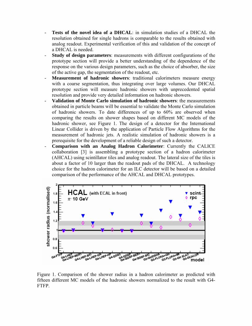
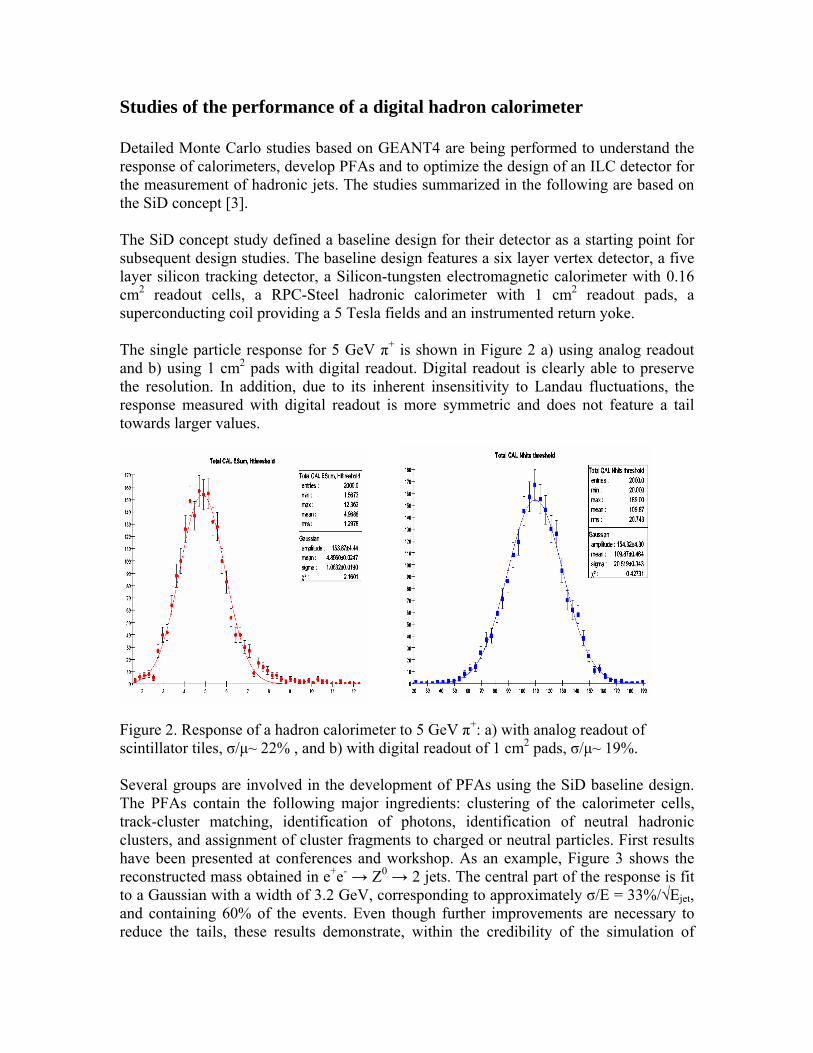
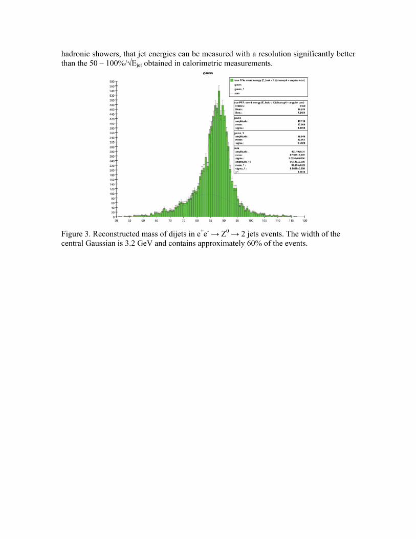
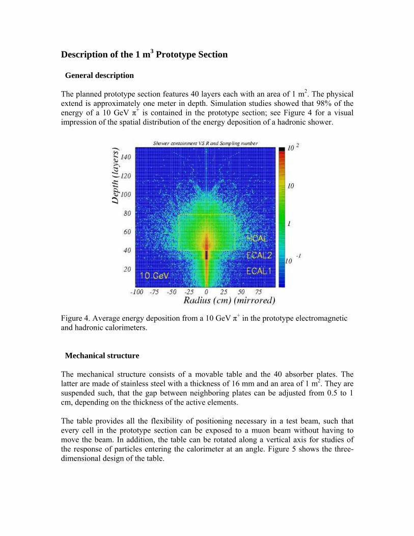
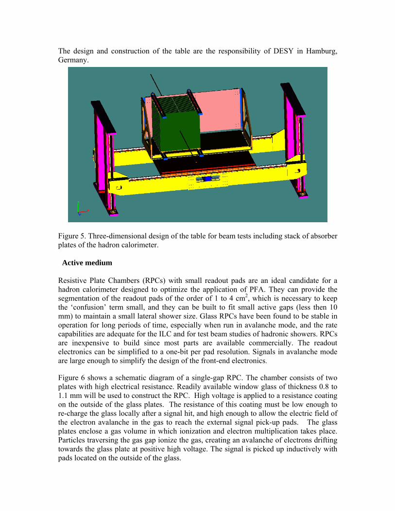
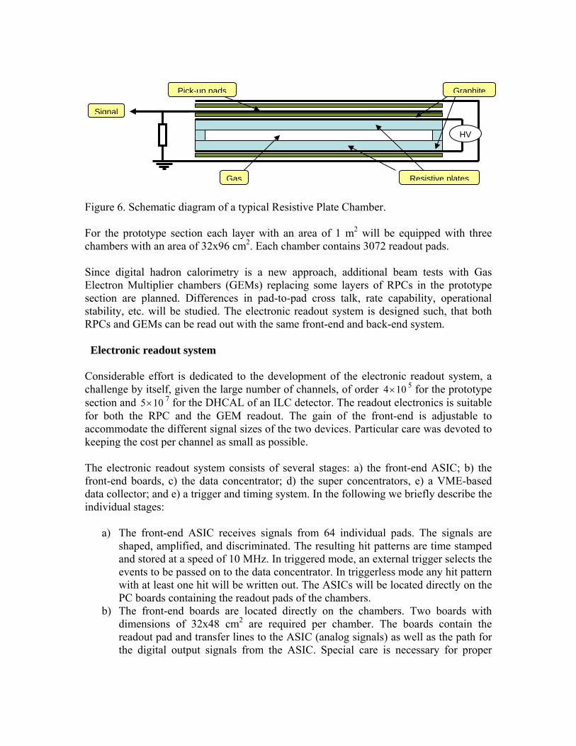
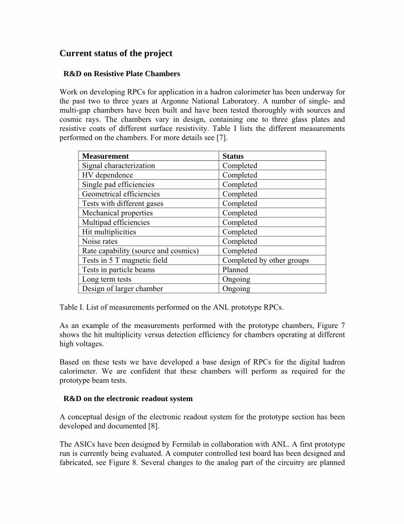
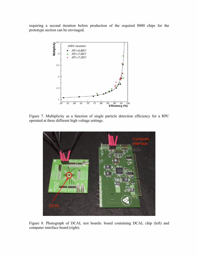
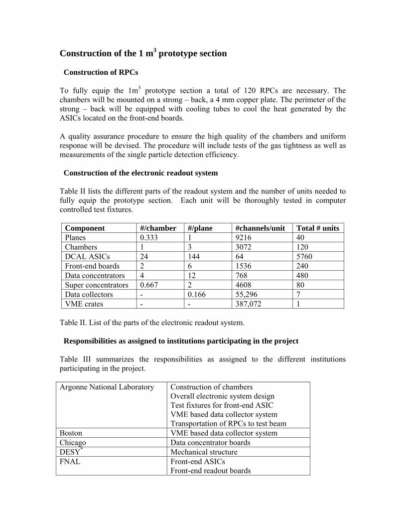
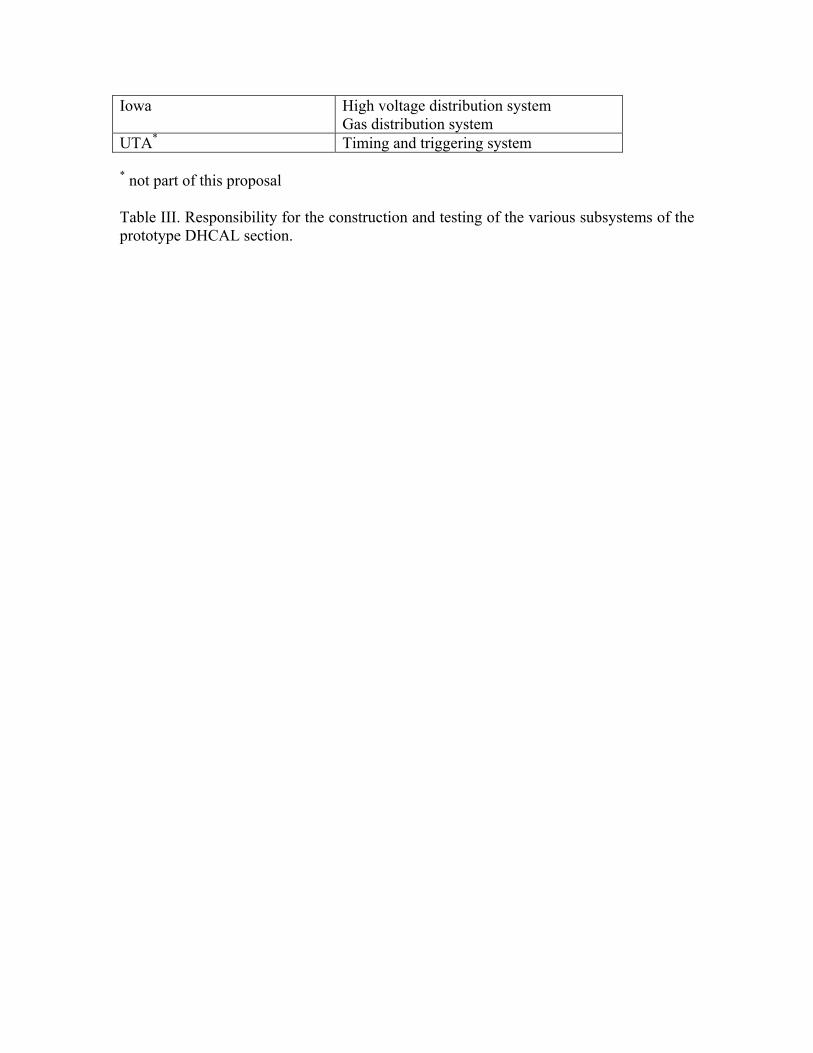
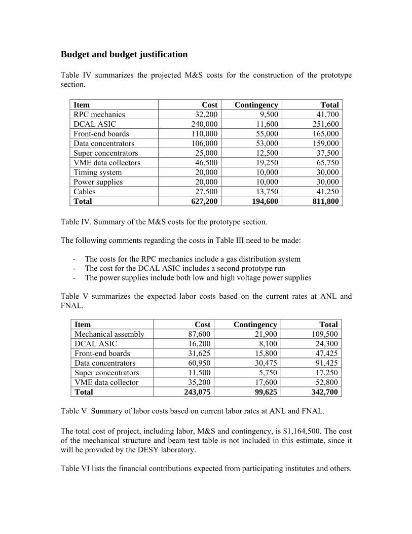
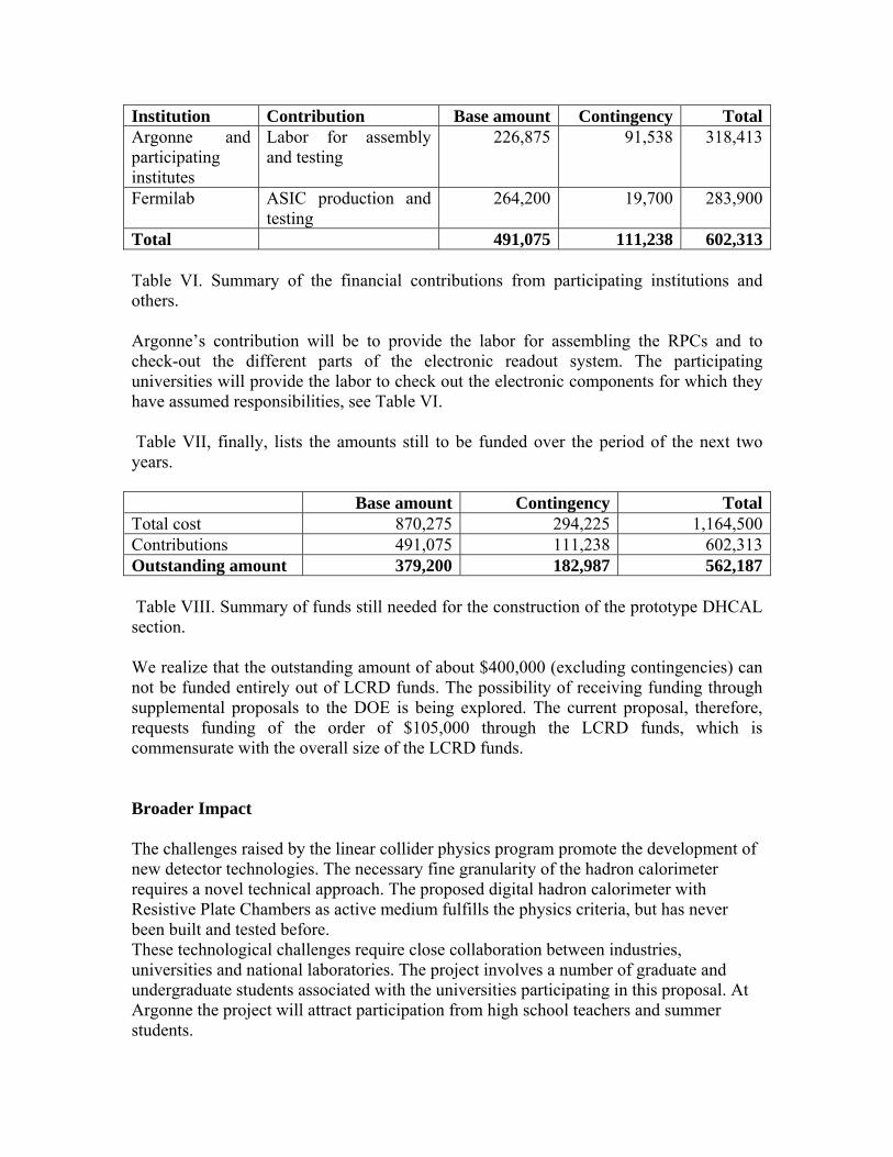
References [1] LCRD proposal by A White et al [2] httppolywwwin2p3frflccalicehtml[3] httpwww-sidslacstanfordedu[4] httpwwwslacstanfordeduxorglcdSiWSiWhtml[5] httpnicaddniueduresearchlcd[6] httpwww-ppdfnalgovmtbf-wMeetingsmtbf_meetingshtm[7] httpwwwhepanlgovrepondDHCAL_UShtml[8] httpwwwhepanlgovreponddcal_sys_desc_113doc[9] httpwwwhepanlgovrepondFNAL-TM-2291-finaldoc