Embed Size (px)
Citation preview
REFRIGERATION AND AIR CONDITIONING
Controller for temperature control- EKC 201C with double thermostat
Manual
2 Manual RS.8D.S1.02 © Danfoss 05-2004 EKC 201C
Introduction
Application• Controller used for temperature control of refrigeration appliances in supermarkets
• On account of the plug connections the controller’s moun ting is primarily intended for OEM’s in the refrigeration appliance industry.
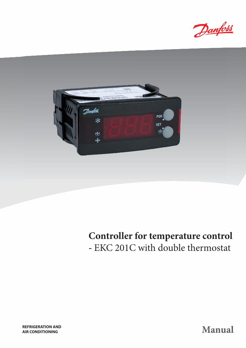
PrincipleThe controller contains a temperature control with a double thermostat function.The thermostat sensors are placed in the cold air current after the evaporator and in the hot air current right in front of the evapora-tor, respectively.Not until both thermostats call for refrigeration will the relay operate.When a “night lid” is placed on the appliance the controller will adapt itself to the changed circumstances.Another option is that only the S
out thermostat is selected to be
active while the Sin
temperature is selected for the display or that the Sin sensor is left out altogether.
ConnectionThe controller is provided with plug connections so that a quick connection can be made without use of screw terminals. Sensors with plug connections can be supplied in given lengths.
Advantages• The controller can itself register whether the night lid is on or
not.
• The controller has integrated refrigeration-technical functions so that it can replace a collection of ther mostats and timers.
• Temperatures, times, operating conditions, parameter codes and alarm and error codes can be read on the display.
•Three LED’s show the system’s actual function: - refrigeration - defrost - fan operating
• When there is an alarm, all three LED’s will fl ash.
• Easy to install data communication at a later date.
Functions• Double thermostat function. (The S
in thermostat can be opted
out).
• Changed alarm limits when night lid is on.
• Relay outputs for- refrigeration (compressor)- fan- defrost- alarm
• Digital inputs for, e.g.: - Coordinated defrost- start of defrost- retransmission of contact position via the data communication
Cooling
"Without night lid" : "With night lid"
EKC 201C Manual RS.8D.S1.02 © Danfoss 05-2004 3
Function
The thermostat
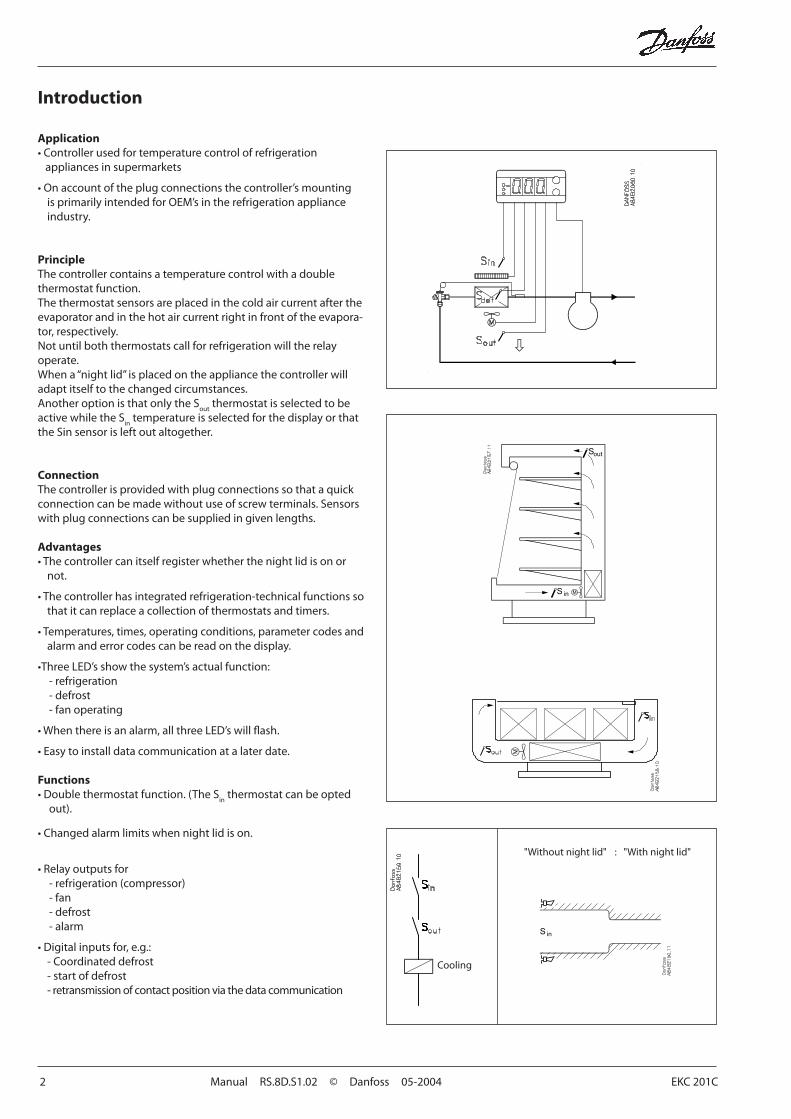
The two temperatures Sin
and Sout
have their own ther mostat func-tion with belonging diff erential. Not until both thermostats call for cold temperatures will refrigeration be started.The setting of the two thermostats is based on the following principle:- The S
in thermostat is set so low that it will always call for refrigera-
tion when the night lid is off - S
out is set, so that it will be the controlling thermostat
- When the night lid is put on, the Sin
temperature will fall and form part of the regulation
- If the refrigerating system works with a higher suction pressure during the night, the S
out thermostat will all the time call for
cold, and accordingly the Sin thermostat will be the controlling thermostat.
Coordinated defrostCoordinated defrost can be carried out in two ways. Either with cable connections between the controllers or via data communica-tion.
Wire connectionsOne of the controllers is defi ned as main controller, and a clock module may be mounted in it, if required. The other controllers are defi ned as secondary controllers.The main controller can now start a defrost of all controllers simultane ously. The individual controllers will carry out the defrost and then go in waiting position until all controllers have con-cluded the defrost. The main controller will subsequently release all controllers to normal regulation.
Defrost via data communicationAll controllers are fi tted with a data communication module and via the override function from a gateway the defrost can be coordinated.
Extra options
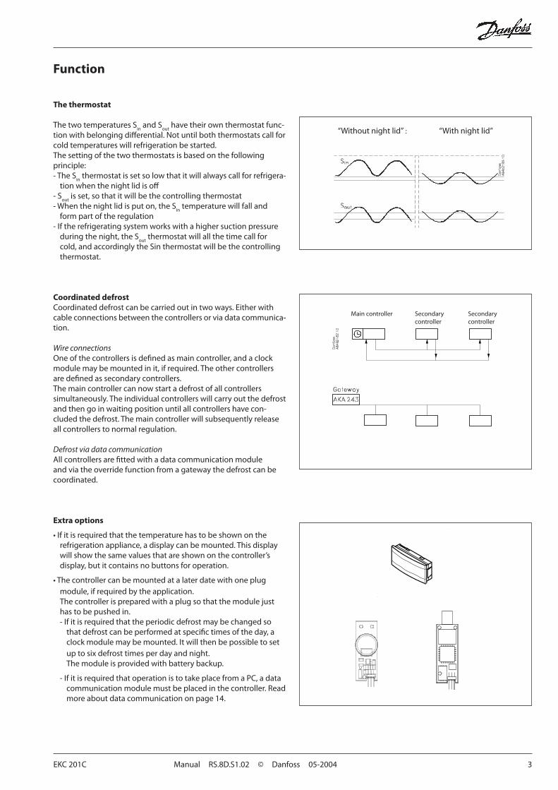
• If it is required that the temperature has to be shown on the refrigera tion appliance, a display can be mounted. This display will show the same values that are shown on the controller’s display, but it contains no buttons for operation.
• The controller can be mounted at a later date with one plug module, if required by the application.The controller is prepared with a plug so that the module just has to be pushed in.- If it is required that the periodic defrost may be changed so
that defrost can be performed at specifi c times of the day, a clock module may be mounted. It will then be possible to set up to six defrost times per day and night.The module is provided with battery backup.
- If it is required that operation is to take place from a PC, a data communication module must be placed in the controller. Read more about data communication on page 14.
“Without night lid” : “With night lid”
Main controller Secondary Secondary controller controller
4 Manual RS.8D.S1.02 © Danfoss 05-2004 EKC 201C
Survey of functionsFunction Para-
meterParameter by operation via data communication
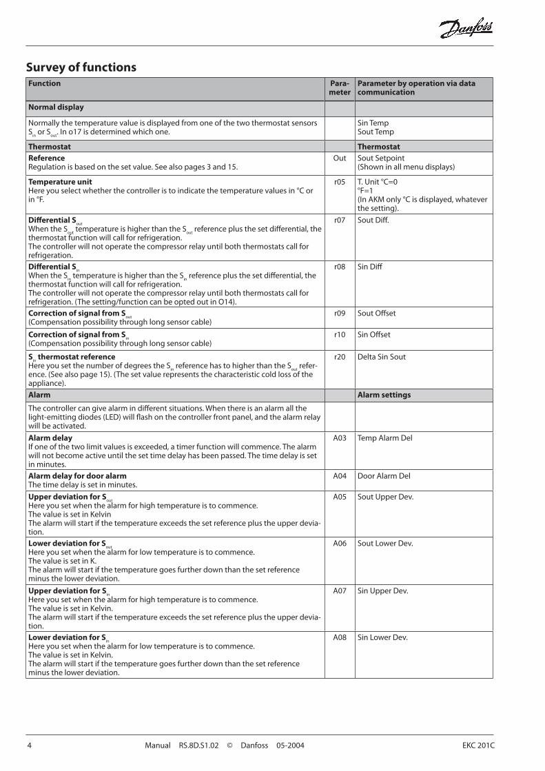
Normal display
Normally the temperature value is displayed from one of the two thermostat sensors S
in or S
out. In o17 is determined which one.
Sin TempSout Temp
Thermostat ThermostatReferenceRegulation is based on the set value. See also pages 3 and 15.
Out Sout Setpoint(Shown in all menu displays)
Temperature unitHere you select whether the controller is to indicate the temperature values in °C or in °F.
r05 T. Unit °C=0°F=1(In AKM only °C is displayed, whatever the setting).
Diff erential Sout
When the Sout
temperature is higher than the Sout
reference plus the set diff erential, the thermostat function will call for refrigeration. The controller will not operate the compressor relay until both thermostats call for refrigeration.
r07 Sout Diff .
Diff erential Sin
When the Sin temperature is higher than the S
in reference plus the set diff erential, the
thermostat function will call for refrigeration. The controller will not operate the compressor relay until both thermostats call for refrigeration. (The setting/function can be opted out in O14).
r08 Sin Diff
Correction of signal from Sout
(Compensation possibility through long sensor cable)r09 Sout Off set
Correction of signal from Sin
(Compensation possibility through long sensor cable)r10 Sin Off set
Sin
thermostat referenceHere you set the number of degrees the S
in reference has to higher than the S
out refer-
ence. (See also page 15). (The set value represents the characteristic cold loss of the appliance).
r20 Delta Sin Sout
Alarm Alarm settings
The controller can give alarm in diff erent situations. When there is an alarm all the light-emitting diodes (LED) will fl ash on the controller front panel, and the alarm relay will be activated.
Alarm delayIf one of the two limit values is exceeded, a timer function will commence. The alarm will not become active until the set time delay has been passed. The time delay is set in minutes.
A03 Temp Alarm Del
Alarm delay for door alarmThe time delay is set in minutes.
A04 Door Alarm Del
Upper deviation for Sout
Here you set when the alarm for high temperature is to commence.The value is set in KelvinThe alarm will start if the temperature exceeds the set reference plus the upper devia-tion.
A05 Sout Upper Dev.
Lower deviation for Sout
Here you set when the alarm for low temperature is to commence.The value is set in K.The alarm will start if the temperature goes further down than the set reference minus the lower deviation.
A06 Sout Lower Dev.
Upper deviation for Sin
Here you set when the alarm for high temperature is to commence.The value is set in Kelvin.The alarm will start if the temperature exceeds the set reference plus the upper devia-tion.
A07 Sin Upper Dev.
Lower deviation for Sin
Here you set when the alarm for low temperature is to commence.The value is set in Kelvin.The alarm will start if the temperature goes further down than the set reference minus the lower deviation.
A08 Sin Lower Dev.
EKC 201C Manual RS.8D.S1.02 © Danfoss 05-2004 5
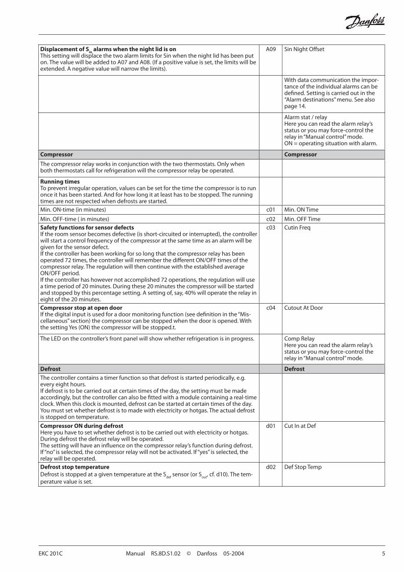
Displacement of Sin alarms when the night lid is onThis setting will displace the two alarm limits for Sin when the night lid has been put on. The value will be added to A07 and A08. (If a positive value is set, the limits will be extended. A negative value will narrow the limits).
A09 Sin Night Off set
With data communication the impor-tance of the individual alarms can be defi ned. Setting is carried out in the “Alarm destinations” menu. See also page 14.
Alarm stat / relayHere you can read the alarm relay’s status or you may force-control the relay in “Manual control” mode. ON = operating situation with alarm.
Compressor Compressor
The compressor relay works in conjunction with the two thermostats. Only when both thermostats call for refrigeration will the compressor relay be operated.
Running timesTo prevent irregular operation, values can be set for the time the compressor is to run once it has been started. And for how long it at least has to be stopped. The running times are not respected when defrosts are started.Min. ON-time (in minutes) c01 Min. ON Time
Min. OFF-time ( in minutes) c02 Min. OFF TimeSafety functions for sensor defectsIf the room sensor becomes defective (is short-circuited or interrupted), the controller will start a control frequency of the compressor at the same time as an alarm will be given for the sensor defect.If the controller has been working for so long that the compressor relay has been operated 72 times, the controller will remember the diff erent ON/OFF times of the compressor relay. The regulation will then continue with the established average ON/OFF period.If the controller has however not accomplished 72 operations, the regulation will use a time period of 20 minutes. During these 20 minutes the compressor will be started and stopped by this percentage setting. A setting of, say, 40% will operate the relay in eight of the 20 minutes.
c03 Cutin Freq
Compressor stop at open doorIf the digital input is used for a door monitoring function (see defi nition in the “Mis-cellaneous” section) the compressor can be stopped when the door is opened. With the setting Yes (ON) the compressor will be stopped.t.
c04 Cutout At Door
The LED on the controller’s front panel will show whether refrigeration is in progress. Comp RelayHere you can read the alarm relay’s status or you may force-control the relay in “Manual control” mode.
Defrost Defrost
The controller contains a timer function so that defrost is started periodically, e.g. every eight hours.If defrost is to be carried out at certain times of the day, the setting must be made accordingly, but the controller can also be fi tted with a module containing a real-time clock. When this clock is mounted, defrost can be started at certain times of the day.You must set whether defrost is to made with electricity or hotgas. The actual defrost is stopped on temperature.
Compressor ON during defrostHere you have to set whether defrost is to be carried out with electricity or hotgas. During defrost the defrost relay will be operated.The setting will have an infl uence on the compressor relay’s function during defrost. If “no” is selected, the compressor relay will not be activated. If “yes” is selected, the relay will be operated.
d01 Cut In at Def
Defrost stop temperatureDefrost is stopped at a given temperature at the S
def sensor (or S
out, cf. d10). The tem-
perature value is set.
d02 Def Stop Temp
6 Manual RS.8D.S1.02 © Danfoss 05-2004 EKC 201C
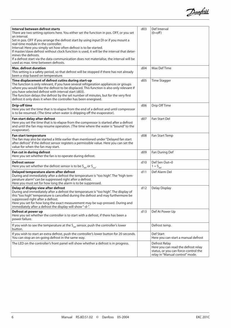
Interval between defrost startsThere are two setting options here. You either set the function in pos. OFF, or you set an interval.Set in pos. OFF if you arrange the defrost start by using input DI or if you mount a real-time module in the controller.Interval: Here you simply set how often defrost is to be started.If master/slave defrost without clock function is used, it will be the interval that deter-mines the defrosts.If a defrost start via the data communication does not materialise, the interval will be used as max. time between defrosts.
d03 Def Interval(0=off )
Max. defrost durationThis setting is a safety period, so that defrost will be stopped if there has not already been a stop based on temperature.
d04 Max Def Time
Time displacement of defrost cutins during start-upThe function is only relevant, if you have several refrigeration appliances or groups where you would like the defrost to be displaced. This function is also only relevant if you have selected defrost with interval start (d03).The function delays the defrost by the set number of minutes, but for the very fi rst defrost it only does it when the controller has been energised.
d05 Time Stagger
Drip-off timeHere you set the time that is to elapse from the end of a defrost and until compressor is to be resumed. (The time when water is dripping off the evaporator).
d06 Drip Off Time
Fan start delay after defrostHere you set the time that is to elapse from the compressor is started after a defrost and until the fan may resume operation. (The time where the water is “bound” to the evaporator).
d07 Fan Start Del
Fan start temperatureThe fan may also be started a little earlier than mentioned under “Delayed fan start after defrost” if the defrost sensor registers a permissible value. Here you can set the value for when the fan may start.
d08 Fan Start Temp
Fan cut in during defrostHere you set whether the fan is to operate during defrost.
d09 Fan During Def
Defrost sensorHere you set whether the defrost sensor is to be S
def or S
out.
d10 Def Sen Out=01 = S
def
Delayed temperature alarm after defrostDuring and immediately after a defrost the temperature is “too high”. The “high tem-perature alarm” can be suppressed right after a defrost. Here you must set for how long the alarm is to be suppressed.
d11 Def Alarm Del
Delay of display view after defrostDuring and immediately after a defrost the temperature is “too high”. The display of this “too high” temperature is cancelled during the defrost and may furthermore be suppressed right after a defrost.Here you set for how long the exact measurement may be sup-pressed. During and immediately after a defrost the display will show “-d-”.
d12 Delay Display
Defrost at power upHere you set whether the controller is to start with a defrost, if there has been a power failure.
d13 Def At Power Up
If you wish to see the temperature at the Sdef
sensor, push the controller’s lower button.
Defrost temp.
If you wish to start an extra defrost, push the controller’s lower button for 20 seconds.You can stop an on-going defrost in the same way.
Def StartHere you can start a manual defrost
The LED on the controller’s front panel will show whether a defrost is in progress. Defrost RelayHere you can read the defrost relay status, or you can force-control the relay in “Manual control” mode.
EKC 201C Manual RS.8D.S1.02 © Danfoss 05-2004 7
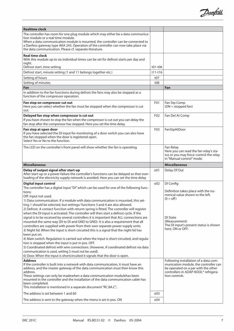
Realtime clockThe controller has room for one plug module which may either be a data communica-tion module or a real-time module.When a data communication module is mounted, the controller can be connected to a Danfoss gateway type AKA 243. Operation of the controller can now take place via the data communication. Please cf. separate literature.
Real time clockWith this module up to six individual times can be set for defrost starts per day and night.Defrost start, time setting t01-t06
Defrost start, minute setting (1 and 11 belongs together etc.) t11-t16
Setting of hours t07Setting of minutes t08Fan FanIn addition to the fan functions during defrost the fans may also be stopped as a function of the compressor operation.
Fan stop on compressor cut outHere you can select whether the fan must be stopped when the compressor is cut out.
F01 Fan Stp Comp (ON = stopped fan)
Delayed fan stop when compressor is cut outIf you have chosen to stop the fan when the compressor is cut out you can delay the fan stop after the compressor has stopped. Here you set the time delay.
F02 Fan Del At Comp
Fan stop at open doorIf you have selected the DI input for monitoring of a door switch you can also have the fan stopped when the door is registered open.Select Yes or No to the function.
F03 FanStpAtDoor
The LED on the controller’s front panel will show whether the fan is operating. Fan RelayHere you can read the fan relay’s sta-tus or you may force-control the relay in “Manual control” mode.
Miscellaneous Miscellaneous
Delay of output signal after start-upAfter start-up or a power failure the controller’s functions can be delayed so that over-loading of the electricity supply network is avoided. Here you can set the time delay
o01 Delay Of Out
Digital input controlThe controller has a digital input “DI” which can be used for one of the following func-tions:Off : Input not used.1) Data communication. If a module with data communication is mounted, this set-ting 1 should be selected, but settings/ functions 3 and 4 are also allowed.2) Defrost. A contact function with returm spring is fi tted. The controller will register when the DI input is activated. The controller will then start a defrost cycle. If the signal is to be received by several controllers it is important that ALL connections are mounted the same way (DI to DI and GND to GND). It is also a requirement that all controllers are supplied with power from their own separate power supply units.3) Night lid. When the input is short-circuited this is a signal that the night lid has been put on.4) Main switch. Regulation is carried out when the input is short-circuited, and regula-tion is stopped when the input is put in pos. OFF.5) Coordinated defrost with wire connections. (However, if coordinated defrost via data communication is used, setting 5 must not be used).6) Door. When the input is shortcircuited it signals that the door is open.
o02 DI Confi g
Defi nition takes place with the nu-merical value shown to the left.(0 = off )
DI State(Measurement)The DI input’s present status is shown here. ON or OFF.
AddressIf the controller is built into a network with data communication, it must have an address, and the master gateway of the data communication must then know this address.These settings can only be madewhen a data communication modulehas been mounted in the controller and the installation of the data communication cable has been completed.This installation is mentioned in a separate document “RC.8A.C”..
Following installation of a data com-munication module, the controller can be operated on a par with the other controllers in ADAP-KOOL® refrigera-tion controls.
The address is set between 1 and 60 o03
The address is sent to the gateway when the menu is set in pos. ON o04
8 Manual RS.8D.S1.02 © Danfoss 05-2004 EKC 201C
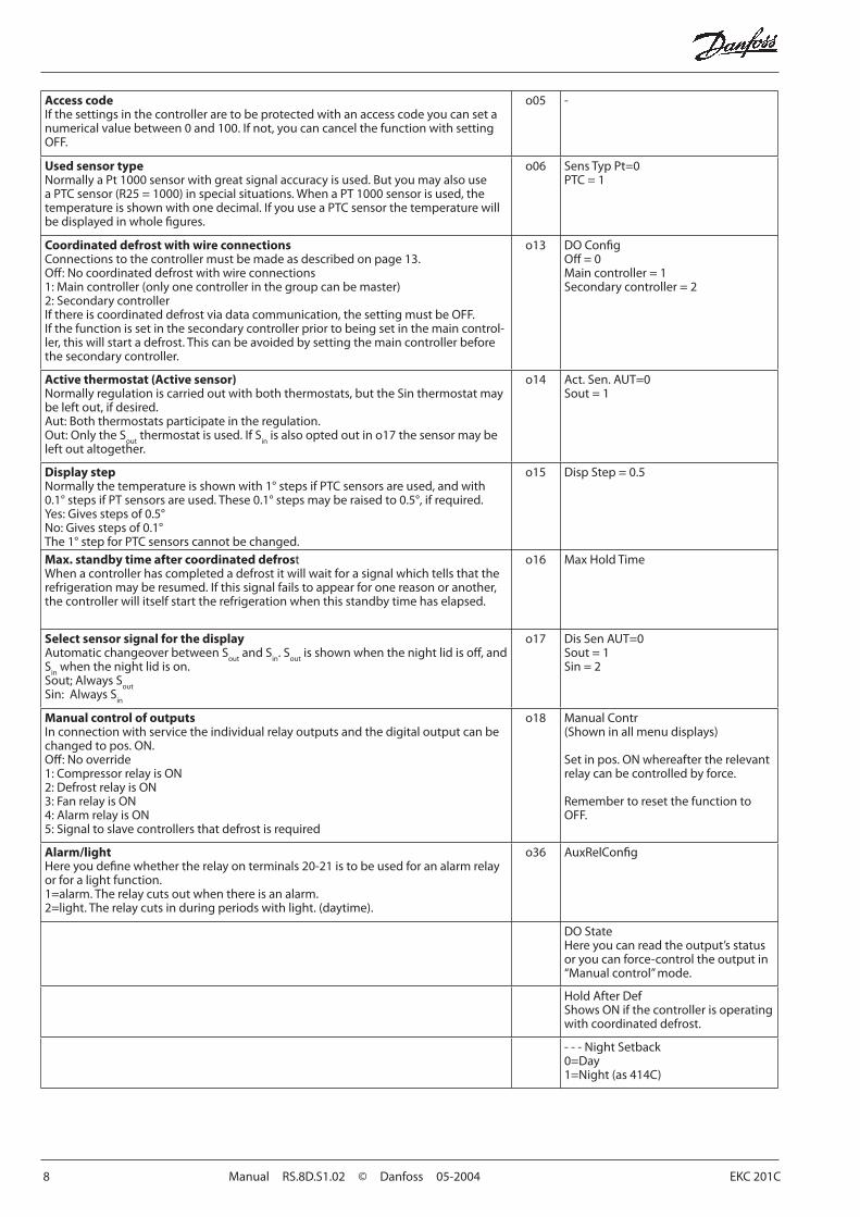
Access codeIf the settings in the controller are to be protected with an access code you can set a numerical value between 0 and 100. If not, you can cancel the function with setting OFF.
o05 -
Used sensor typeNormally a Pt 1000 sensor with great signal accuracy is used. But you may also use a PTC sensor (R25 = 1000) in special situations. When a PT 1000 sensor is used, the temperature is shown with one decimal. If you use a PTC sensor the temperature will be displayed in whole fi gures.
o06 Sens Typ Pt=0PTC = 1
Coordinated defrost with wire connectionsConnections to the controller must be made as described on page 13.Off : No coordinated defrost with wire connections1: Main controller (only one controller in the group can be master)2: Secondary controllerIf there is coordinated defrost via data communication, the setting must be OFF.If the function is set in the secondary controller prior to being set in the main control-ler, this will start a defrost. This can be avoided by setting the main controller before the secondary controller.
o13 DO Confi gOff = 0Main controller = 1Secondary controller = 2
Active thermostat (Active sensor)Normally regulation is carried out with both thermostats, but the Sin thermostat may be left out, if desired.Aut: Both thermostats participate in the regulation.Out: Only the S
out thermostat is used. If S
in is also opted out in o17 the sensor may be
left out altogether.
o14 Act. Sen. AUT=0Sout = 1
Display stepNormally the temperature is shown with 1° steps if PTC sensors are used, and with 0.1° steps if PT sensors are used. These 0.1° steps may be raised to 0.5°, if required.Yes: Gives steps of 0.5°No: Gives steps of 0.1°The 1° step for PTC sensors cannot be changed.
o15 Disp Step = 0.5
Max. standby time after coordinated defrostWhen a controller has completed a defrost it will wait for a signal which tells that the refrigeration may be resumed. If this signal fails to appear for one reason or another, the controller will itself start the refrigeration when this standby time has elapsed.
o16 Max Hold Time
Select sensor signal for the displayAutomatic changeover between S
out and S
in. S
out is shown when the night lid is off , and
Sin
when the night lid is on.Sout; Always S
outSin: Always S
in
o17 Dis Sen AUT=0Sout = 1Sin = 2
Manual control of outputsIn connection with service the individual relay outputs and the digital output can be changed to pos. ON.Off : No override1: Compressor relay is ON2: Defrost relay is ON3: Fan relay is ON4: Alarm relay is ON5: Signal to slave controllers that defrost is required
o18 Manual Contr(Shown in all menu displays)
Set in pos. ON whereafter the relevant relay can be controlled by force.
Remember to reset the function to OFF.
Alarm/lightHere you defi ne whether the relay on terminals 20-21 is to be used for an alarm relay or for a light function.1=alarm. The relay cuts out when there is an alarm.2=light. The relay cuts in during periods with light. (daytime).
o36 AuxRelConfi g
DO StateHere you can read the output’s status or you can force-control the output in “Manual control” mode.
Hold After DefShows ON if the controller is operating with coordinated defrost.
- - - Night Setback0=Day1=Night (as 414C)
EKC 201C Manual RS.8D.S1.02 © Danfoss 05-2004 9
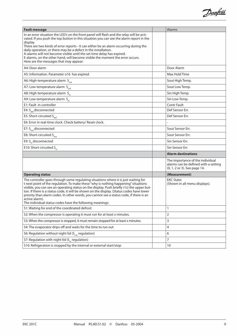
Fault message Alarms
In an error situation the LED’s on the front panel will fl ash and the relay will be acti-vated. If you push the top button in this situation you can see the alarm report in the display.There are two kinds of error reports - it can either be an alarm occurring during the daily operation, or there may be a defect in the installation.A-alarms will not become visible until the set time delay has expired. E-alarms, on the other hand, will become visible the moment the error occurs.Here are the messages that may appear:
A4: Door alarm Door Alarm
A5: Information. Parameter o16 has expired Max Hold Time
A6: High-temperature alarm Sout
Sout High Temp.
A7: Low-temperature alarm Sout
Sout Low Temp.
A8: High-temperature alarm Sin
Sin High Temp.
A9: Low-temperature alarm Sin
Sin Low Temp.
E1: Fault in controller Contr Fault
E4: Sdef
disconnected Def Sensor Err.
E5: Short-circuited Sdef
Def Sensor Err.
E6: Error in real-time clock. Check battery/ Reset clock. -
E7: Sout
disconnected Sout Sensor Err.
E8: Short-circuited Sout
Sout Sensor Err.
E9: Sin
disconnected Sin Sensor Err.
E10: Short-circuited Sin
Sin Sensor Err.
Alarm destinations
The importance of the individual alarms can be defi ned with a setting (0, 1, 2 or 3). See page 14.
Operating status (Measurement)
The controller goes through some regulating situations where it is just waiting for t next point of the regulation. To make these “why is nothing happening” situations visible, you can see an operating status on the display. Push briefl y (1s) the upper but-ton. If there is a status code, it will be shown on the display. (Status codes have lower priority than alarm codes. In other words, you cannot see a status code, if there is an active alarm).The individual status codes have the following meanings:
EKC State:(Shown in all menu displays).
S1: Waiting for end of the coordinated defrost 1
S2: When the compressor is operating it must run for at least x minutes. 2
S3: When the compressor is stopped, it must remain stopped for at least x minutes. 3
S4: The evaporator drips off and waits for the time to run out 4
S6: Regulation without night lid (Sout
regulation) 6
S7: Regulation with night lid (Sin
regulation) 7
S10: Refrigeration is stopped by the internal or external start/stop 10
10 Manual RS.8D.S1.02 © Danfoss 05-2004 EKC 201C
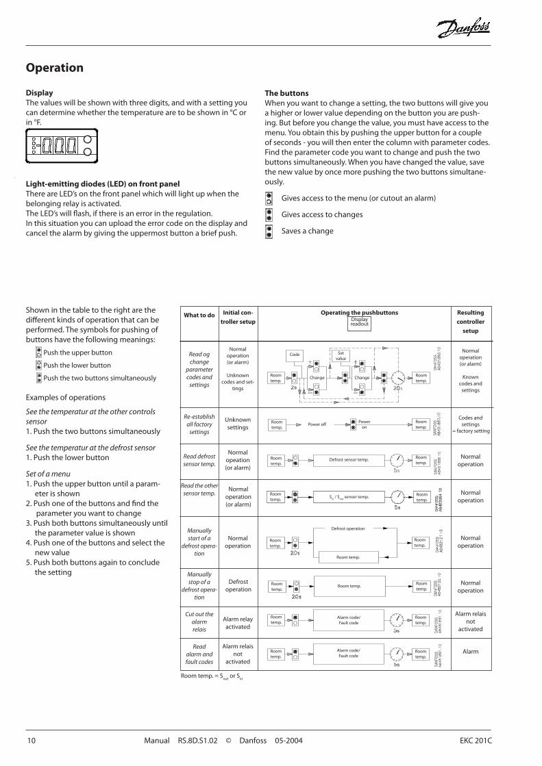
Light-emitting diodes (LED) on front panelThere are LED’s on the front panel which will light up when the belonging relay is activated.The LED’s will fl ash, if there is an error in the regulation.In this situation you can upload the error code on the display and cancel the alarm by giving the uppermost button a brief push.
DisplayThe values will be shown with three digits, and with a setting you can determine whether the temperature are to be shown in °C or in °F.
Operation
The buttonsWhen you want to change a setting, the two buttons will give you a higher or lower value depending on the button you are push-ing. But before you change the value, you must have access to the menu. You obtain this by pushing the upper button for a couple of seconds - you will then enter the column with parameter codes. Find the parameter code you want to change and push the two buttons simultaneously. When you have changed the value, save the new value by once more pushing the two buttons simultane-ously.
Gives access to the menu (or cutout an alarm)
Gives access to changes
Saves a change
Shown in the table to the right are the diff erent kinds of operation that can be performed. The symbols for pushing of buttons have the following meanings:
Push the upper button
Push the lower button
Push the two buttons simultaneously
Examples of operations
See the temperatur at the other controls sensor1. Push the two buttons simultaneously
See the temperatur at the defrost sensor1. Push the lower button
Set of a menu1. Push the upper button until a param-
eter is shown2. Push one of the buttons and fi nd the
parameter you want to change3. Push both buttons simultaneously until
the parameter value is shown4. Push one of the buttons and select the
new value5. Push both buttons again to conclude
the setting
Operating the pushbuttonsDisplayreadout
Resulting controller
setup
Normal operation(or alarm)
Known codes and
settings
Codes and settings
= factory setting
Normal operation
Normal operation
Normal operation
Alarm relaisnot
activated
Alarm
ChangeChange
Setvalue
Room temp.
Room temp.
Power off Power
on
Room temp.
Room temp.
Room temp.
Room temp.
Room temp.
Alarm code/Fault code
Alarm code/Fault code
Room temp.
Room temp.
Defrost operation
Defrost sensor temp.
What to do Initial con-troller setup
Read og change
parameter codes and
settings
Re-establish all factory
settings
Read defrost sensor temp.
Manually start of a
defrost opera-tion
Manually stop of a
defrost opera-tion
Cut out the alarm relais
Read alarm andfault codes
Normaloperation(or alarm)
Unknowncodes and set-
tings
Unknown settings
Normal opeation(or alarm)
Normal operation
Defrost operation
Alarm relay activated
Alarm relais not
activated
Room temp.
Code
Room temp.
Room temp.
Room temp.
Room temp.
Room temp.
Room temp.
Read the other sensor temp. Normal
operationRoom temp.
Sin
/ Sout
sensor temp.
Normal operation(or alarm)
Room temp.
Room temp. = Sout
or Sin
EKC 201C Manual RS.8D.S1.02 © Danfoss 05-2004 11
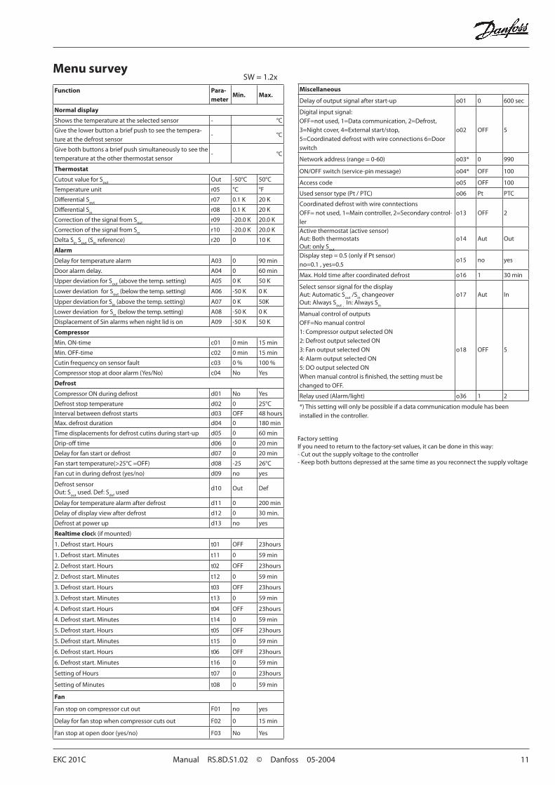
Menu survey
Factory settingIf you need to return to the factory-set values, it can be done in this way:- Cut out the supply voltage to the controller- Keep both buttons depressed at the same time as you recon nect the supply voltage
Function Para-meter
Min. Max.
Normal display
Shows the temperature at the selected sensor - °C
Give the lower button a brief push to see the tempera-ture at the defrost sensor
- °C
Give both buttons a brief push simultaneously to see the temperature at the other thermostat sensor
- °C
Thermostat
Cutout value for Sout
Out -50°C 50°C
Temperature unit r05 °C °F
Diff erential Sout
r07 0.1 K 20 K
Diff erential Sin
r08 0.1 K 20 K
Correction of the signal from Sout
r09 -20.0 K 20.0 K
Correction of the signal from Sin
r10 -20.0 K 20.0 K
Delta Sin
Sout
(Sin
reference) r20 0 10 K
Alarm
Delay for temperature alarm A03 0 90 min
Door alarm delay. A04 0 60 min
Upper deviation for Sout
(above the temp. setting) A05 0 K 50 K
Lower deviation for Sout
(below the temp. setting) A06 -50 K 0 K
Upper deviation for Sin
(above the temp. setting) A07 0 K 50K
Lower deviation for Sin
(below the temp. setting) A08 -50 K 0 K
Displacement of Sin alarms when night lid is on A09 -50 K 50 K
Compressor
Min. ON-time c01 0 min 15 min
Min. OFF-time c02 0 min 15 min
Cutin frequency on sensor fault c03 0 % 100 %
Compressor stop at door alarm (Yes/No) c04 No Yes
Defrost
Compressor ON during defrost d01 No Yes
Defrost stop temperature d02 0 25°C
Interval between defrost starts d03 OFF 48 hours
Max. defrost duration d04 0 180 min
Time displacements for defrost cutins during start-up d05 0 60 min
Drip-off time d06 0 20 min
Delay for fan start or defrost d07 0 20 min
Fan start temperature(>25°C =OFF) d08 -25 26°C
Fan cut in during defrost (yes/no) d09 no yes
Defrost sensorOut: S
out used. Def: S
def used
d10 Out Def
Delay for temperature alarm after defrost d11 0 200 min
Delay of display view after defrost d12 0 30 min.
Defrost at power up d13 no yes
Realtime clock (if mounted)
1. Defrost start. Hours t01 OFF 23hours
1. Defrost start. Minutes t11 0 59 min
2. Defrost start. Hours t02 OFF 23hours
2. Defrost start. Minutes t12 0 59 min
3. Defrost start. Hours t03 OFF 23hours
3. Defrost start. Minutes t13 0 59 min
4. Defrost start. Hours t04 OFF 23hours
4. Defrost start. Minutes t14 0 59 min
5. Defrost start. Hours t05 OFF 23hours
5. Defrost start. Minutes t15 0 59 min
6. Defrost start. Hours t06 OFF 23hours
6. Defrost start. Minutes t16 0 59 min
Setting of Hours t07 0 23hours
Setting of Minutes t08 0 59 min
Fan
Fan stop on compressor cut out F01 no yes
Delay for fan stop when compressor cuts out F02 0 15 min
Fan stop at open door (yes/no) F03 No Yes
Miscellaneous
Delay of output signal after start-up o01 0 600 sec
Digital input signal:OFF=not used, 1=Data communication, 2=Defrost, 3=Night cover, 4=External start/stop, 5=Coordinated defrost with wire connections 6=Door switch
o02 OFF 5
Network address (range = 0-60) o03* 0 990
ON/OFF switch (service-pin message) o04* OFF 100
Access code o05 OFF 100
Used sensor type (Pt / PTC) o06 Pt PTC
Coordinated defrost with wire conntectionsOFF= not used, 1=Main controller, 2=Secondary control-ler
o13 OFF 2
Active thermostat (active sensor)Aut: Both thermostats Out: only S
out
o14 Aut Out
Display step = 0.5 (only if Pt sensor)no=0.1 , yes=0.5
o15 no yes
Max. Hold time after coordinated defrost o16 1 30 min
Select sensor signal for the displayAut: Automatic S
out /S
in changeover
Out: Always Sout
,
In: Always Sin
o17 Aut In
Manual control of outputsOFF=No manual control1: Compressor output selected ON2: Defrost output selected ON3: Fan output selected ON4: Alarm output selected ON5: DO output selected ONWhen manual control is fi nished, the setting must be changed to OFF.
o18 OFF 5
Relay used (Alarm/light) o36 1 2
*) This setting will only be possible if a data communication module has been installed in the controller.
SW = 1.2x
12 Manual RS.8D.S1.02 © Danfoss 05-2004 EKC 201C
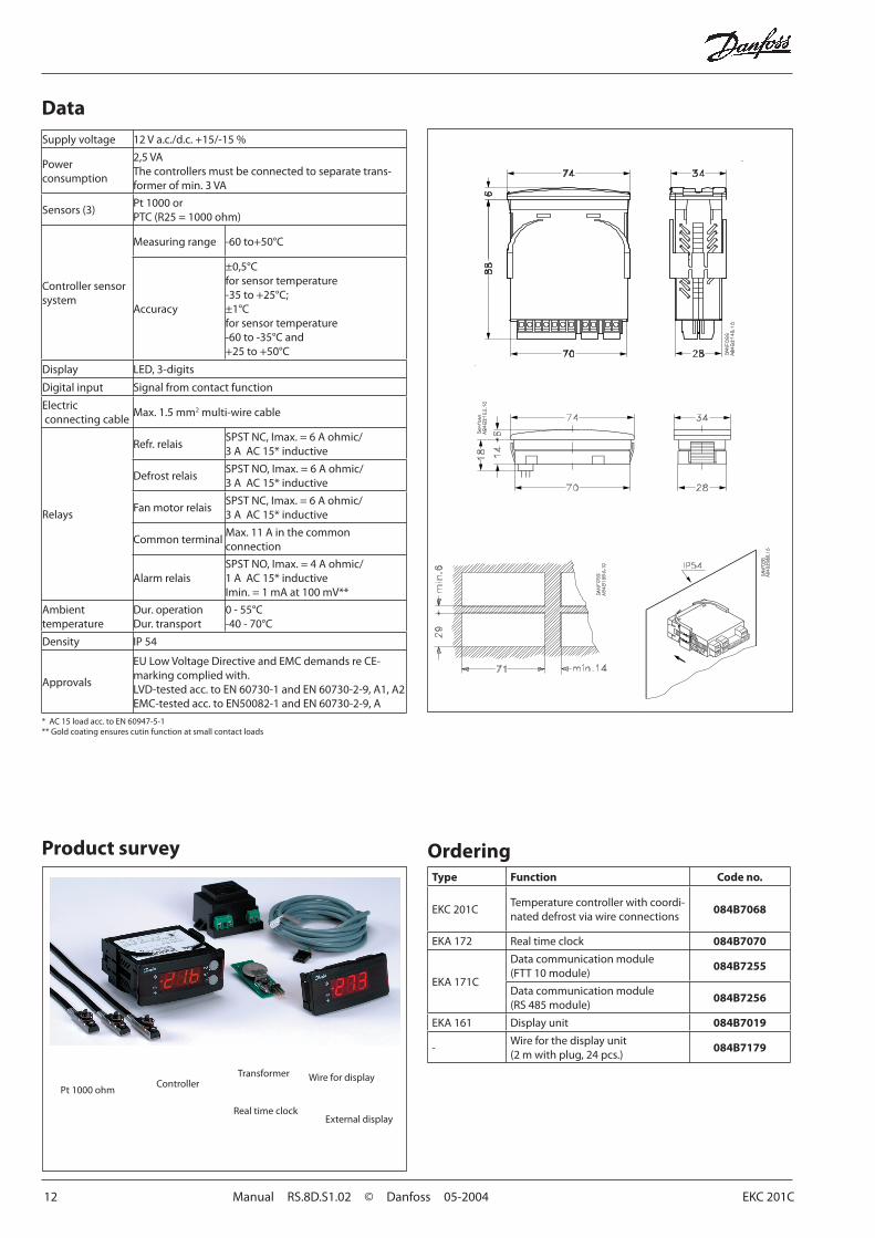
Data
OrderingType Function Code no.
EKC 201CTemperature controller with coordi-nated defrost via wire connections
084B7068
EKA 172 Real time clock 084B7070
EKA 171C
Data communication module (FTT 10 module)
084B7255
Data communication module (RS 485 module)
084B7256
EKA 161 Display unit 084B7019
-Wire for the display unit (2 m with plug, 24 pcs.)
084B7179
Supply voltage 12 V a.c./d.c. +15/-15 %
Power consumption
2,5 VAThe controllers must be connected to separate trans-former of min. 3 VA
Sensors (3)Pt 1000 orPTC (R25 = 1000 ohm)
Controller sensor system
Measuring range -60 to+50°C
Accuracy
±0,5°Cfor sensor temperature-35 to +25°C;±1°Cfor sensor temperature-60 to -35°C and+25 to +50°C
Display LED, 3-digits
Digital input Signal from contact function
Electric connecting cable
Max. 1.5 mm2 multi-wire cable
Relays
Refr. relaisSPST NC, Imax. = 6 A ohmic/3 A AC 15* inductive
Defrost relaisSPST NO, Imax. = 6 A ohmic/3 A AC 15* inductive
Fan motor relaisSPST NC, Imax. = 6 A ohmic/3 A AC 15* inductive
Common terminalMax. 11 A in the common connection
Alarm relaisSPST NO, Imax. = 4 A ohmic/1 A AC 15* inductiveImin. = 1 mA at 100 mV**
Ambient temperature
Dur. operationDur. transport
0 - 55°C-40 - 70°C
Density IP 54
Approvals
EU Low Voltage Directive and EMC demands re CE-marking complied with.LVD-tested acc. to EN 60730-1 and EN 60730-2-9, A1, A2EMC-tested acc. to EN50082-1 and EN 60730-2-9, A
* AC 15 load acc. to EN 60947-5-1** Gold coating ensures cutin function at small contact loads
Product survey
Pt 1000 ohm
Transformer
Real time clock
Wire for display
External display
Controller
EKC 201C Manual RS.8D.S1.02 © Danfoss 05-2004 13
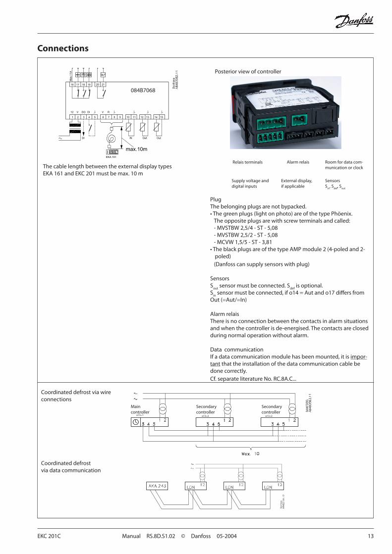
Connections
Posterior view of controller
PlugThe belonging plugs are not bypacked.• The green plugs (light on photo) are of the type Phöenix.
The opposite plugs are with screw terminals and called:- MVSTBW 2,5/4 - ST - 5,08- MVSTBW 2,5/2 - ST - 5,08- MCVW 1,5/5 - ST - 3,81
• The black plugs are of the type AMP module 2 (4-poled and 2-poled)(Danfoss can supply sensors with plug)
SensorsS
out sensor must be connected. S
def is optional.
Sin
sensor must be connected, if o14 = Aut and o17 diff ers from Out (=Aut/=In)
Alarm relaisThere is no connection between the contacts in alarm situations and when the controller is de-energised. The contacts are closed during normal operation without alarm.
Data communicationIf a data communication module has been mounted, it is impor-tant that the installation of the data communication cable be done correctly. Cf. separate literature No. RC.8A.C...
084B7068
Relais terminals Alarm relais Room for data com-munication or clock
Supply voltage and digital inputs
External display,if applicable
SensorsS
in, S
def, S
out
Coordinated defrostvia data communication
Coordinated defrost via wire connections
Main Secondary Secondarycontroller controller controller
The cable length between the external display typesEKA 161 and EKC 201 must be max. 10 m
o13=1 o13=2 o13=2
14 Manual RS.8D.S1.02 © Danfoss 05-2004 EKC 201C
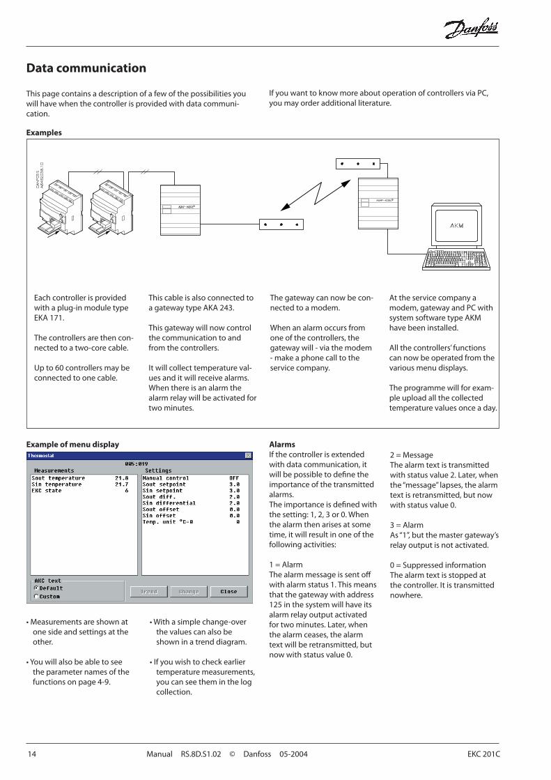
Data communication
Examples
Example of menu display
If you want to know more about operation of controllers via PC, you may order additional literature.
This page contains a description of a few of the possibilities you will have when the controller is provided with data communi-cation.
Each controller is provided with a plug-in module type EKA 171.
The controllers are then con-nected to a two-core cable.
Up to 60 controllers may be connected to one cable.
This cable is also connected to a gateway type AKA 243.
This gateway will now control the communication to and from the controllers.
It will collect temperature val-ues and it will receive alarms. When there is an alarm the alarm relay will be activated for two minutes.
The gateway can now be con-nected to a modem.
When an alarm occurs from one of the controllers, the gateway will - via the modem - make a phone call to the service company.
At the service company a modem, gateway and PC with system software type AKM have been installed.
All the controllers’ functions can now be operated from the various menu displays.
The programme will for exam-ple upload all the collected tempera ture values once a day.
• Measurements are shown at one side and settings at the other.
• You will also be able to see the parameter names of the functions on page 4-9.
• With a simple change-over the values can also be shown in a trend diagram.
• If you wish to check earlier temperature measurements, you can see them in the log collection.
AlarmsIf the controller is extended with data communication, it will be possible to defi ne the importance of the transmitted alarms.The importance is defi ned with the setting: 1, 2, 3 or 0. When the alarm then arises at some time, it will result in one of the following activities:
1 = AlarmThe alarm message is sent off with alarm status 1. This means that the gateway with address 125 in the system will have its alarm relay output activated for two minutes. Later, when the alarm ceases, the alarm text will be retransmitted, but now with status value 0.
2 = MessageThe alarm text is transmitted with status value 2. Later, when the “message” lapses, the alarm text is retransmitted, but now with status value 0.
3 = AlarmAs “1”, but the master gateway’s relay output is not activated.
0 = Suppressed informationThe alarm text is stopped at the controller. It is transmitted nowhere.
EKC 201C Manual RS.8D.S1.02 © Danfoss 05-2004 15
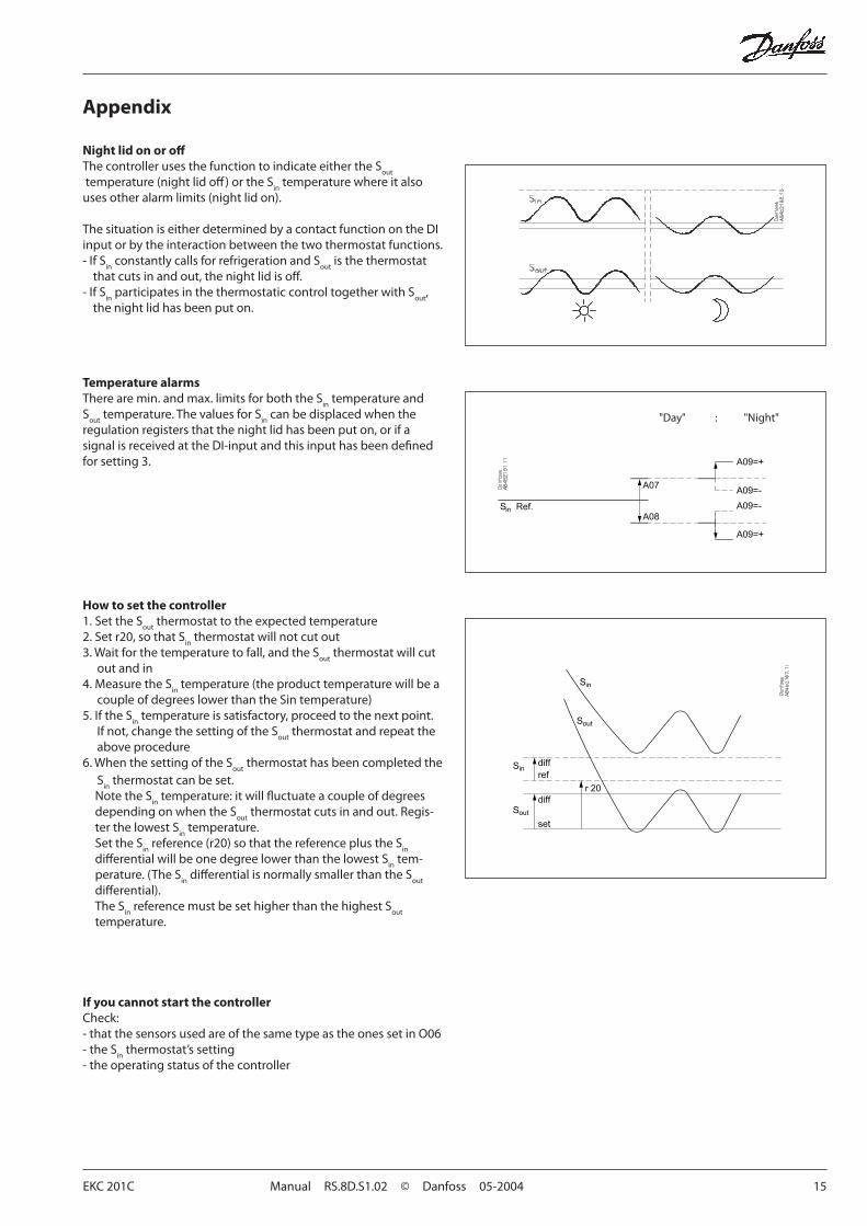
Appendix
Night lid on or off The controller uses the function to indicate either the S
out
temperature (night lid off ) or the Sin
temperature where it also uses other alarm limits (night lid on).
The situation is either determined by a contact function on the DI input or by the interaction between the two thermostat functions.- If S
in constantly calls for refrigeration and S
out is the thermostat
that cuts in and out, the night lid is off .- If S
in participates in the thermostatic control together with S
out,
the night lid has been put on.
Temperature alarmsThere are min. and max. limits for both the S
in temperature and
Sout
temperature. The values for Sin
can be displaced when the regulation registers that the night lid has been put on, or if a signal is received at the DI-input and this input has been defi ned for setting 3.
How to set the controller1. Set the S
out thermostat to the expected temperature
2. Set r20, so that Sin
thermostat will not cut out3. Wait for the temperature to fall, and the S
out thermostat will cut
out and in4. Measure the S
in temperature (the product temperature will be a
couple of degrees lower than the Sin temperature)5. If the S
in temperature is satisfactory, proceed to the next point.
If not, change the setting of the Sout
thermostat and repeat the above procedure
6. When the setting of the Sout
thermostat has been completed the S
in thermostat can be set.
Note the Sin
temperature: it will fl uctuate a couple of degrees depending on when the S
out thermostat cuts in and out. Regis-
ter the lowest Sin
temperature.Set the S
in reference (r20) so that the reference plus the S
in
diff erential will be one degree lower than the lowest Sin
tem-perature. (The S
in diff erential is normally smaller than the S
out
diff erential).The S
in reference must be set higher than the highest S
out
temperature.
If you cannot start the controllerCheck:- that the sensors used are of the same type as the ones set in O06- the S
in thermostat’s setting
- the operating status of the controller
"Day" : "Night"
16 Manual RS.8D.S1.02 © Danfoss 05-2004 EKC 201C
RC-E
T
Danfoss can accept no responsibility for possible errors in catalogues, brochures and other printed material. Danfoss reserves the right to alter its products without notice. This also applies to products already on order provided that such alternations can be made without subsequential changes being necessary in specifi cations already agreed.All trademarks in this material are property of the respecitve companies. Danfoss and Danfoss logotype are trademarks of Danfoss A/S. All rights reserved.