Embed Size (px)
Citation preview

CONTENTS
Central and Distributed CoMP Processing pg. 3
CoMP in Downlink pg. 4
CoMP in Uplink pg. 5
Carrier and Data Aggregation pg. 6
Adaptive Traffic Shapping pg. 6
CoMP: Why and How Does it Matter to Us? pg. 7
OverviewLightRadio, Liquid Radio and Cloud RAN—the fundamentals behind these three seemingly incongruent solutions are very sound but the commonalities between these solutions are strikingly similar. Over the past few years, end users of services have become impatient for increases in per-user throughput with an underscored demand for consistency in service quality. The Release 11 work item in 3GPP, Coordinated Multipoint TX and RX (CoMP), aims at addressing three of the most important problems plaguing the telecoms industry: (a) spectral efficiency, (b) cell-edge throughput and (c) coordinated coverage.
White Paper
Coordinated Multipoint Tx and RxBy: Nagi Mahalingam, Chief Architect
2Coordinated Multipoint Tx and Rx | Radisys White Paper
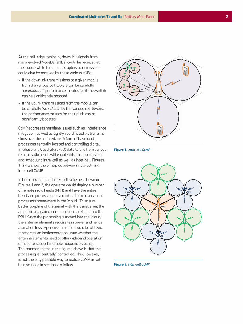
At the cell-edge, typically, downlink signals from many evolved NodeBs (eNBs) could be received at the mobile while the mobile’s uplink transmissions could also be received by these various eNBs.
• If the downlink transmissions to a given mobile from the various cell towers can be carefully ‘coordinated’, performance metrics for the downlink can be significantly boosted
• If the uplink transmissions from the mobile can be carefully ‘scheduled’ by the various cell towers, the performance metrics for the uplink can be significantly boosted
CoMP addresses mundane issues such as ‘interference mitigation’ as well as tightly coordinated bit transmis-sions over the air interface. A farm of baseband processors centrally located and controlling digital In-phase and Quadrature (I/Q) data to and from various remote radio heads will enable this joint coordination and scheduling intra-cell as well as inter-cell. Figures 1 and 2 show the principles between intra-cell and inter-cell CoMP.
In both Intra-cell and Inter-cell schemes shown in Figures 1 and 2, the operator would deploy a number of remote radio heads (RRH) and have the entire baseband processing moved into a farm of baseband processors somewhere in the ‘cloud.’ To ensure better coupling of the signal with the transceiver, the amplifier and gain control functions are built into the RRH. Since the processing is moved into the ‘cloud,’ the antenna elements require less power and hence a smaller, less expensive, amplifier could be utilized. It becomes an implementation issue whether the antenna elements need to offer wideband operation or need to support multiple frequencies/bands. The common theme in the figures above is that the processing is ‘centrally’ controlled. This, however, is not the only possible way to realize CoMP as will be discussed in sections to follow. Figure 2. Inter-cell CoMP
Figure 1. Intra-cell CoMP

3Coordinated Multipoint Tx and Rx | Radisys White Paper
The RRH to baseband processing farm link will be Common Public Radio Interface (CPRI)-based, typically carried over an optical network. The latest version of CPRI, v4.2, has all the provisions detailing synchronization and timing, delay calibration, link accuracy and I/Q bit widths. These apply equally to UMTS Terrestrial Radio Access (UTRA) and Evolved UTRA (E-UTRA). A properly dimensioned network can see a farm of baseband processors serving RRHs placed as far away as 30 to 40 kilometers while still meeting dimensioned latency budgets.
Central and Distributed CoMP ProcessingFor CoMP to work, the downlink channel should be known prior to the transmission. Mobiles perform channel estimations and provide Channel quality, Rank Index, Precoding matrix index and Channel state information to the eNB serving the connected mode mobile. There are two possible methods for CoMP to be realized:
• Centrally controlled CoMP processing
• Distributed CoMP processing
In the central approach, a common farm of processors—centrally located—makes use of Channel State information, Channel Quality Indicator (CQI), Pre-coding Matrix Index (PMI) and Rank Indicator (RI) reported by the mobile to decide which sets of RRH are best suited for serving the mobile. It is important to note at this point that since the processing is centrally controlled, the central processors will handle all the digital signal processing. The I/Q waveforms for transmission are pre-computed at the central farm of processors and distilled into the set of RRHs that are best suited to serve the mobile. The data hauling to and from the RRH is via a CPRI interface as mentioned earlier and the bandwidth requirement to handle I/Q waveforms in either direction can be in gigabits per second depending on the capacity the RRH is dimensioned to provide. Centrally controlled CoMP is illustrated by the ‘Green’ colored mobile centrally controlled by eNB number 1 (eNB#1) in Figure 3.
In the distributed approach, however, processing is done at more than one eNB but with joint coordination. This enables them to control multiple users as well, if required. In this approach CQI, RI, PMI and Channel state information is being received from the mobile at each of these coordinating eNBs. Distributed CoMP is illustrated by the ‘Blue’ colored mobile controlled by eNB#1 and eNB#2 in Figure 3. In the distributed approach, the transmission waveforms are computed at each of the eNBs and hence there is no need for an RRH. Further, there is no latency associated with this process at the front end. Since the signal processing is done locally at each eNB, the radio front ends at each of the eNBs need to be very tightly bound for synchronization. The precise clock reference can either be from a global positioning system (GPS) tick or network-based protocols such as SyncE and Precision Time Protocol (PTP). It becomes necessary that two eNBs in distributed CoMP must transmit the same data symbol at the same resource element in the time-frequency grid.
Figure 3. Central and Distributed CoMP processing

4Coordinated Multipoint Tx and Rx | Radisys White Paper
For distributed CoMP, the precoding is done at each of the eNBs. Figure 4 shows the use case of two eNBs in distributed CoMP handling two separate users enabling joint scheduling and beamforming. Data bits coming into the Media Access Control (MAC) layer at both eNBs are formed into transport blocks after HARQ (Hybrid Automatic Repeat ReQuest) processing. These transport blocks are encoded (forward error correction, interleaving), mapped into symbols and then into appropriate resource elements within a resource block. Note the mobile-specific and cell-specific pilot insertion in Figure 4; the link between the two eNBs is, for instance, X2. Data exchanged between the two eNBs will be over the ‘wire’ (Ethernet, for example) and some header-like information is signaled to indicate which resource blocks have CoMP mode enforced.
A point to note from above is that the precoding vector is nothing but a multiplicative complex number. The I/Q bits at the eNB are precoded before the IFFT (Inverse Fast Fourier Transform) operation. The feedback from the mobiles (CQI, PMI, RI and Channel state information) is required at the MIMO (multiple-input and multiple-output) input stage of the eNB. ACK/NACK (acknowledgement/negative acknowledgement) processing is at the HARQ with the output of the CODEC unit in the mobile feeding back that information.
Since the MAC layer processing is already completed in the respective eNB, latencies due to data exchange are compensated for by implementing buffers before the precoder. On the user equipment (UE) side, the precoded channel is estimated at each mobile. The channel estimation is multi-cell, multi-user and symbol equalization is performed by Interference Rejection Combining. There is a downside to this in the sense that channel estimation at the mobile is a lot more complex, but the net benefit is a system-wide improvement in capacity.
CoMP in the DownlinkGenerally speaking, downlink CoMP is performed as follows:
• A transmission to a given mobile is done by the cell serving the mobile (connected mode mobile). However, the transmissions are ‘beamformed’ from the serving cell to the mobile such that interference due to that downlink transmission to other network elements is either eliminated or reduced. This ‘beamforming’ is performed by means of joint coordination between the various cell towers.
• A transmission to a given mobile will be performed by many cell towers (at least two). However, the transmission is scheduled such that it is seen by the mobile as a single transmitter with spatially diverse antenna elements.
Figure 4. Distributed CoMP processing at eNB Tx and precoding

5Coordinated Multipoint Tx and Rx | Radisys White Paper
Looking into this deeper, there are three methods discussed in the 3GPP standards to address downlink CoMP:
BeamformingIn CoMP schemes, control channels such as PDCCH are only ever transmitted from the serving cell. In Figure 5, ‘Coordinated Scheduling’ is shown in which data channel PDSCH is transmitted only from one cell. The scheduling is coordinated among multiple cells. This has the benefit of increased SINR (Signal to Interference plus Noise Ratio) which directly translates to an increase in cell-edge performance metrics.
Fast SelectionIn Fast Selection, the eNB transmitting the PDSCH having the lowest path loss is instantaneously selected through fast scheduling at the central eNB. Since only one eNB is selected for transmission, all the other transmitters among the coordinated cells are not scheduled. The advantage of this method is that the muting of cells (non-scheduling) will have the net result of decreased interference at the mobile, thus providing maximum received signal power at the mobile.
Joint SchedulingIn Joint Scheduling, the PDSCH is transmitted from multiple cells with codebook base precoding, at each coordinated cell, using demodulation reference pilots. Specific lobe weights (beamforming weights) are added before transmission. The throughput at the cell edge sees a significant improvement as more than one cell participates in the coherent transmission of resource elements. The mobile combines the received signal coherently using a coherent combining receiver.
CoMP in the UplinkOn the uplink, the PUSCH is received at multiple cells. In Figure 8, the two possible CoMP methods on the uplink are illustrated. In the left side of Figure 8, only one mobile transmits the PUSCH and is scheduled by the coordinated eNBs. On the right side of Figure 8, multiple mobiles transmit the PUSCH simultaneously using same resource block. In this method, upon reception of PUSCH the cells use various estimation schemes to recover the PUSCH. Looking at it from another view point, limiting interference from the
Figure 5. Coordinated Scheduling (beamforming)
Figure 6. Fast Selection
Figure 7. Joint Scheduling

6Coordinated Multipoint Tx and Rx | Radisys White Paper
mobile at the receiver, whether intended of unintended, is purely a scheme that will involve implementing clever schedulers and receivers. Since it can be addressed entirely by a given ‘implementation,’ uplink CoMP does not have much standards impact.
Carrier and Data AggregationCarrier Aggregation is the method in which two or more component carriers are combined to increase the total system capacity. It is to be noted that non-contiguous carrier aggregation is likely to be the common method for frequency aggregation. This poses a problem if, for different component carriers, differing methods should be implemented for resource allocation, modulation and coding scheme support selection, transmit power setting, etc. Data Aggregation can either be handled at the physical (PHY) layer or at the MAC layer. If the PHY layer aggregation option is chosen, HARQ must be used for the ‘aggregated data’ rather than the ‘component data’ from the component carriers. In practice, this is very inefficient to support and, as a result, it is more than likely for data aggregation to take place at the MAC layer as shown in Figure 9.
Carrier aggregation on the uplink and downlink can be asymmetric; the number of component carriers on the uplink and downlink can be different in size and number. In TDD (time division duplexing) mode, asymmetric carrier aggregation can be achieved by allocating different number of time slots for uplink and downlink.
Adaptive Traffic ShappingImprovements to backhaul capacity will lag all advancements made on the Radio Access Network (RAN) side by a number of years. Even taking current High Speed Packet Access (HSPA) deployments into account, the packet networks form the bottleneck and the promise of gigantic increases in per-user throughput is far from reality—and LTE and LTE-Advanced deployments will accentuate this problem. The logical answer, of course, is to augment wired backhaul capacity by installing or adding passive optical networks. But this is not a singular solution that will cap the problems at hand. Quality of Service and Quality of Experience need to be guaranteed for
Figure 8. Uplink CoMP
Figure 9. Carrier and Data Aggregation

7Coordinated Multipoint Tx and Rx | Radisys White Paper
Corporate Headquarters5435 NE Dawson Creek Drive
Hillsboro, OR 97124 USA 503-615-1100 | Fax 503-615-1121
Toll-Free: 800-950-0044 www.radisys.com | [email protected]
©2011 Radisys Corporation. Radisys, Trillium, Continuous Computing and Convedia
are registered trademarks of Radisys Corporation. *All other trademarks are the properties of their respective owners.
September 2011
subscribers that pay a premium. Prioritizing traffic on a subscription basis or on traffic class/traffic type basis requires inspection of traffic from various users in either direction, at line speed, taking into account capacity on the uplink and downlink directions in addition to application type, time of day and other service level principles.
Bringing this ‘intelligence’ into the eNB itself helps unblock congestion to and from eNBs and facilitates user and eNB load balancing from the Evolved Packet Core (EPC) view point. A traffic-shaped RAN grants the operator better Key Performance Indices (KPI).
CoMP: Why and How Does it Matter to Us?Moving the baseband processing to a ‘farm’ in the cloud would mean larger, more powerful processors, possibly with multiple cores. However, as hinted in sections above, this calls for changes that the industry should adopt but has yet to do so:
• CoMP hints at the possibility of multiple ‘radio access technologies’ to co-exist at the front end: this is essentially the software defined radio (SDR) concept. As a result, the baseband as well as the radio stacks running on the processor farms will have to become multi-mode capable to address this need.
• Cloud RAN calls for real, carrier-grade joint schedulers, interfaces to content servers, manipulation of content at line speed, true distributed MIMO processing and several other value added services.
At Radisys, we are aware of the constant need to keep abreast of rapid, radical changes in the communications industry. The company’s Trillium® Advanced Portability Architecture (TAPA®) is platform-agnostic and is readily portable across all platforms and processor architectures. TAPA is woven into the fabric of every Trillium software product, individual or combined, and hence forms the cornerstone of ‘product consistency.’ The fundamental design of TAPA enables itself to auto-align and scale to function on a single core or across multiple cores. Radisys welcomes CoMP and sees it as a logical progression to providing better and greater service to end users. From a practical viewpoint, subscribers should see corner scenarios disappear as CoMP-enabled networks exhibit tighter control of mobiles, thereby giving rise to increased reliability of services (for example, significantly reduced call drops due to mobility).


![index [] · index p 02—09 comp. 175 p 10—19 comp. 176 p 20—25 comp. 177 p 26—31 comp. 178 p 32—37 comp. 179 p 38—43 comp. 180 p 44—49 comp. 181 p 50—55 comp. 182 p](https://img.pdfslide.net/doc/110x75/5c66627e09d3f252168c4378/index-index-p-0209-comp-175-p-1019-comp-176-p-2025-comp-177.jpg)


![index []...p 104—109 comp. 190 p 110—115 comp. 191 p 116—121 comp. 192 p 122—127 comp. 193 p 128—133 comp. 194 p 134—139 comp. 195 p 140—147 comp. 196 p 148—153 comp](https://img.pdfslide.net/doc/110x75/5f95526362174b59db2f2d15/index-p-104a109-comp-190-p-110a115-comp-191-p-116a121-comp-192.jpg)