Embed Size (px)
Citation preview

Copyright Warning & Restrictions
The copyright law of the United States (Title 17, United States Code) governs the making of photocopies or other
reproductions of copyrighted material.
Under certain conditions specified in the law, libraries and archives are authorized to furnish a photocopy or other
reproduction. One of these specified conditions is that the photocopy or reproduction is not to be “used for any
purpose other than private study, scholarship, or research.” If a, user makes a request for, or later uses, a photocopy or reproduction for purposes in excess of “fair use” that user
may be liable for copyright infringement,
This institution reserves the right to refuse to accept a copying order if, in its judgment, fulfillment of the order
would involve violation of copyright law.
Please Note: The author retains the copyright while the New Jersey Institute of Technology reserves the right to
distribute this thesis or dissertation
Printing note: If you do not wish to print this page, then select “Pages from: first page # to: last page #” on the print dialog screen

The Van Houten library has removed some of the personal information and all signatures from the approval page and biographical sketches of theses and dissertations in order to protect the identity of NJIT graduates and faculty.

ABSTRACT
A MICROFLUIDIC CULTURE FOR TWO POPULATIONS OF
DROSAL ROOT GANGLIA FOR DIFFERENTIAL STAINING
by
Ishnoor Sidhu
The goal of this study was to design and fabricate a microfluidic system that can be used
to visibly distinguish the two populations of dorsal root ganglia (DRGs) by differential
staining. Polydimethylsiloxane (PDMS) is the most widely used silicon-based organic
polymer, and is particularly known for its wide spread use in microfluidics. Various
methods have been employed to pump fluids in these channels for applications ranging
from patterning of cells and biomolecules to control of local environment factors such as
temperature, which requires external pumping or other applied forces. We demonstrated a
pump-free device that exploits the surface energy stored in a liquid droplet to pump liquid
in the channels. The fluid was pumped by using two droplets of unequal sizes connected
via fluid filled channel. The flow was generated from smaller droplet to larger droplet.
This passive pumping technique was used to simultaneously stain the two cultured DRGs
in connected channels.
The in vitro system can be further exploited to study the guided growth in axons.
This study provides a cost effective method to detect the influence of the presence of
pioneer neuron on the growth patterns of the new generation of neurons. It eliminates the
need of using transgenic cells to study the guided growth in axons, thereby giving some
insight for the repair of spinal cord injuries and the understanding of the early growth
model.

A MICROFLUIDIC CULTURE FOR TWO POPULATIONS OF
DROSAL ROOT GANGLIA FOR DIFFERENTIAL STAINING
by
Ishnoor Sidhu
A Thesis
Submitted to the Faculty of
New Jersey Institute of Technology
in Partial Fulfillment of the Requirements for the Degree of
Master of Science in Biomedical Engineering
Department of Biomedical Engineering
May 2011


APPROVAL PAGE
A MICROFLUIDIC CULTURE FOR TWO POPULATIONS OF
DROSAL ROOT GANGLIA FOR DIFFERENTIAL STAINING
Ishnoor Sidhu
Dr. Raquel Perez-Castillejos, Thesis Advisor Date
Assistant Professor, Electrical Engineering, NJIT
Dr. Bryan J. Pfister, Committee Member Date
Assistant Professor, Biomedical Engineering, NJIT
Dr. Cheul H Cho, Committee Member Date
Assistant Professor, Biomedical Engineering, NJIT
BIOGRAPHICAL SKETCH
Author : Ishnoor Sidhu
Degree: Master of Science
Date: May 2011
Undergraduate and Graduate Education:
• Master of Science in Biomedical Engineering,New Jersey Institute of Technology, Newark, NJ, 2011
• Bachelor of Technology in Biotechnology,Kurukshetra University, Kurukshetra, India, 2008
Major: Biomedical Engineering
iv

v
To my beloved family and friends, I never would have been able to do this without your love and support; you make me who I am.

vi
ACKNOWLEDGMENT
Foremost, I would like to acknowledge the advice and guidance of Dr. Raquel Perez-
Castillejos for her invaluable support and encouragement during the course of the
research work. Her insights, wisdoms, advices and enthusiasm for research have greatly
influenced me and made the completion of my thesis possible. I have been very fortunate
to have her as my mentor.
I am indebted to the members of my thesis committee, Dr. Bryan J. Pfister and Dr.
Cheul H. Cho, for their valuable suggestions and actively participating in my research
and defense.
I am thankful to the members of Tissue Models Lab and Dr. Pfister’s lab who
contributed in smoothing the bumps along my road to Mastery, especially Anil Shrirao
and Neha Jain.
I am indebted to my parents, Mr. Gurtinder Singh and Mrs. Narinder Kaur, who
raised me not just to be smart, but to know how to learn and excel and be nice doing it. I
am also thankful to Pankaj Marwah who was always there to support me throughout my
masters.

vii
TABLE OF CONTENTS
Chapter Page
1 INTRODUCTION…………………………………………………………….. 1
1.1 Human Nervous System ….…………………………………………….. 1
1.1.1 The Neuron: Cell of Nervous System …………………………... 1
1.1.2 The Spinal Cord …..…………………………………………….. 4
1.1.3 Dorsal Root Ganglion Neuron ………………………………….. 6
1.2 Motivation for Using Microfluidics in Neuroscience Research ...……… 6
1.3 Microfluidics ……………………………………………………………. 7
1.3.1 Polydimethylsiloxane (PDMS) …..……………………………... 8
1.3.2 Characteristics of Flow …………………………………………. 10
2 BACKGROUND………………………………………………………………. 13
2.1 Neuroscience Study in Microchannels: Literature Review ……………. 13
2.2 Flow in Channels ……………………………………………………….. 17
3 RESEARCH OBJECTIVE……………………………………………………. 19
4 EXPERIMENTAL DESIGN …………………………………………………. 20
5 EXPERIMENTAL SETUP ………………………………………………….... 21
5.1 General Plating of DRGs …...…………………………………………... 21
5.1.1 Explant Isolation ……………………………………………… 21
5.1.2 Pre-plating Procedure ………………………………………….. 22
5.1.3 Medium Preparation …………………………………………... 23
5.1.4 Plating Procedure ……………………………………………… 23

viii
TABLE OF CONTENTS
(Continued)
Chapter Page
5.2 Fabrication of PDMS Microchannels …………………………………. 24
5.2.1 Fabrication of Scotch Tape Master …………………………… 24
5.2.2 Replica Molding ……………………………………………… 25
5.3 Cell Culture in PDMS Microchannels ………………………………… 26
5.3.1 Pre-plating Procedure …………...……………………………. 26
5.3.2 Plating Procedure ……..………………………………………. 27
5.4 Fabrication of PDMS Open Channels ………………………………… 28
5.5 Cell Culture in PDMS Open Channels …………..….………………… 30
5.5.1 Pre-plating Procedure …………...……………………………. 30
5.5.2 Plating Procedure ……..………………………………………. 31
5.6 Passive Pumping and Fluidic Isolation …………………….…………. 32
5.6.1 Fluidic Isolation in Microchannels …………………………… 32
5.6.2 Fluidic Isolation in Open Channels …...……………………… 32
5.7 Staining of Two DRGs ………………………………………………... 34
5.7.1 Calcein AM Stock Solution ….……………………………….. 34
5.7.2 Cell Tracker Orange CMRA Stock Solution …………………. 34
5.7.3 Staining in Open Channels …………………………………… 35
6 RESULTS AND DISCUSSION ..…………………………………………… 36
6.1 General Plating ………………...……………………………………… 36
6.2 Neurite Growth in Microchannels ….…………………………………. 37

ix
TABLE OF CONTENTS
(Continued)
Chapter Page
6.3 Neurite Growth in Open Channels …….……………………………… 41
6.4 Fluidic Isolation ……....……………………………………………….. 42
6.5 Staining of Two DRGs ……..…………………………………………. 44
7 CONCLUSIONS …………………………………………………………….. 48
REFERENCES ………..………………………………………………………….. 49

x
LIST OF TABLES
Table Page
5.1 Reagents for Growth Medium for DRGs …………………………………... 23

xi
LIST OF FIGURES
Figure Page
1.1 Structure of neuron (A) CNS neuron, (B) a lower motor neuron located
both in CNS and PNS, (C) Axodendritic synapse between two neurons, (D)
Motor end plate (synapse), and (X) border between CNS (above X) and
PNS (below X). The lower motor neuron synapses with a voluntary muscle
cell to form a motor end plate ……………………………………………….
3
1.2 Anatomy of the spine. (A) The spinal column (front and back). The spinal
column extends from skull to pelvis and is divided into five regions:
Cervical, Thoracic, Lumbar, Sacrum and Coccyx. (B) Spinal nerves. Each
spinal nerve controls a specific part of body………………………………...
4
1.3 The spinal nerve. Each spinal nerve divided into roots, Dorsal (sensory) and
Ventral (motor) roots………………………………………………………...
5
1.4 Chemical representation of PDMS………………………………………….. 9
4.1 Flow chart showing experimental design …………………………………... 20
5.1 Layout of the microchannel. The microchannel is in shape of H. Each arm
has length of 15 mm and width of 3 mm. The separation between two arms
is 5 mm ……………………………………………………………………...
24
5.2 “H” microchannels with 4 mm reservoirs punched ………………………... 26
5.3 Schematic of plating. PDMS device is shown by grey and blue color shows
the microchannels facing the plate. 1, 2, 3, and 4 shows the reservoirs of
4mm diameter each. DRG explants are plated in reservoir 1 and 4 ………...
28
5.4 3D Master. (a) Layout of the 3D master, and (b) ABS master printed on 3D
printer ……………………………………………………………………….
29
5.5 Schematics of plating in open channels …………………………………….. 31
5.6 Schematics of open channels with ceiling. (a) Top view, grey shows the
PDMS slab with channels and blue shows the ceiling on top of channels
with four holes of 1.5 mm diameter each, and (b) 3D view ………………...
33
6.1 Day 3 images of DRGs grown in control plates with (a) 5 μl, and (b) 1 μl of
plating medium ……………………………………………………………..
36

xii
LIST OF FIGURES
(Continued)
Figure Page
6.2 Day 20 image of DRG of reservoir 1 in 60 μm high microchannels .………. 37
6.3 DRG in microchannels with 120 μm height. (a) DRG1 in reservoir 1 on day
3, (b) DRG2 in reservoir 4 on day 3 ………………………………………...
38
6.4 DRG 1 in reservoir 1 in microchannels with 120 µm height on day 12 ……. 39
6.5 DRG 2 in reservoir 4 in microchannels with 120 µm height on day 12 ……. 40
6.6 Day 5 culture of DRGs in open channel ……………………………………. 41
6.7 Fluidic isolation in microchannels with 100μl of water droplets and 5μl of
green and red inks. (a) after 10 minutes and (b) after 30 minutes …………..
42
6.8 Fluidic isolation in microchannels with 100 μl of water droplets and 1μl of
green and red inks after 30 minutes …………………………………………
43
6.9 Fluidic isolation in open channels with 100 μl of water droplets and 5 μl of
green and red inks after 10 minutes …………………………………………
43
6.10 Fluidic isolation in open channels with 100 μl of water droplets and 1μl of
green and red inks after 20 minutes ……………………………………….
44
6.11 DRG1 stained with calcein in open channel arm1 ………………………….
45
6.12 DRG2 stained with orange tracker in open channel arm2 …………………. 46

1
CHAPTER 1
INTRODUCTION
1.1 Human Nervous System
Human nervous system exhibits bilateral symmetry. It is subdivided into central nervous
system and peripheral nervous system, anatomically. Functionally it is divided into
somatic nervous system and autonomic nervous system. The CNS comprises the brain
and spinal cord, whereas PNS consist of the cranial nerves (nerves emerging from the
brain) and spinal nerves (nerves emerging from the spinal cord). The PNS convey neural
message from sensory organs to CNS and vice versa. The somatic nervous system is
responsible for sensory information (afferent) and motor (efferent) control of voluntary
muscles. The autonomic nervous system, also called as visceral nervous system is
concerned with motor control of involuntary and cardiac muscles and of glands of
viscera.
1.1.1 The Neuron: Cell of Nervous System
The neuron is the basic unit of the nervous system. There are billions of neurons in
human body. Over 100 billion neurons along with many more glial cells are integrated
together to form brain. They exhibit various forms and sizes. A typical neuron consists of
four morphologically defined regions:
1.1.1.1 Soma or Cell Body. As any other, soma is the metabolic center of the neuron.
It contains large nucleus, plasma membrane, cytosol, Nissl bodies and endoplasmic
reticulum, mitochondria, lysosomes, neurotubules, and neurofilaments (Noback et al.,
1996).

2
1.1.1.2 Dendrites. Dendrites, or the nerve endings, are the variable number of small
branching projections. These allow cell to talk to other neuron or perceive the
environment. Dendrites contain same cytoplasmic organelles as the cell body (Noback et
al., 1996).
1.1.1.3 Axon. Axons are long, cable-like projections. The axon is specialized for
transmission of coded information (nerve impulse or action potential). The axons of CNS
are very thin, of the order of 0.2 to 20 microns as compared to diameter of the cell body,
about 50 microns (Kandel et al., 1991). It arises from axon hillock of cell body and
extends from less than a millimeter to as long as 3 meter before diverging into fine
terminal branches, telondria.
Depending upon the type of neuron, axons can be covered with a thin layer
of myelin, like an insulated electrical wire. Myelin is made of mostly fat (glycolipid
called galactocerebroside), and it helps to speed transmission of a nerve impulse down a
long axon. Myelinated neurons are typically found in the PNS, while non-myelinated
neurons are found in the CNS.
1.1.1.4 Synapse. A synapse is a junction where one neuron meets another neuron’s
impulse. A synapse has a pre-synaptic component, usually an axon terminal, and a post-
synaptic component, part of dendrite, cell body or axonal initial segment (Kandel et al.,
1991). A pre-synaptic cell does not actually touch or communicate anatomically with the
post-synaptic cell since the two cells are separated by a space, the synaptic cleft.
The pre-synaptic cell releases the signal (chemical or electrical) into the synaptic
cleft and is received by the post-synaptic cleft.

3
Figure 1.1 Structure of neuron (A) CNS neuron, (B) a lower motor neuron located both
in CNS and PNS, (C) Axodendritic synapse between two neurons, (D) Motor end plate
(synapse), and (X) border between CNS (above X) and PNS (below X). The lower motor
neuron synapses with a voluntary muscle cell to form a motor end plate.
Source: (Noback et al., 1996)
Figure 1.1 describes the basic morphology of neurons in central nervous system
and peripheral nervous system and how the neurons communicate with each other i.e.,
how the signal is transported from CNS to PNS and vice versa.

4
1.1.2 The Spinal Cord
The spinal cord is a cylinder that extends from the foramen magnum at the base of skull
to a cone-shaped termination (conus medullaris), located at the caudal level of the first
lumbar centrum. The nonneural filament continues from conus medullaris to its
attachment in the coccyx.
Figure 1.2 Anatomy of the spine. (A) The spinal column (front and back). The spinal
column extends from skull to pelvis and is divided into five regions: Cervical, Thoracic,
Lumbar, Sacrum and Coccyx. (B) Spinal nerves. Each spinal nerve controls a specific
part of body.
Source: (http://www.thewellingtonneurosurgeryunit.com/spine-anatomy.asp)

5
The spinal column is divided into five regions, as shown in Figure 1.2 (A). There
are 33 bones which forms the spinal column. The first three regions, cervical, thoracic,
and lumbar, are made of number of individual vertebrates; there are seven cervical
vertebrate, 12 thoracic vertebrate and five lumbar vertebrate. The sacrum region consists
of five fused bones and the coccyx (tail-bone) is a single bone.
Figure 1.2 (B) shows the spinal nerves. The spinal cord receives its input and
projects the output via spinal nerves. Each spinal nerve is two components, dorsal root
and ventral root, see Figure 1.3. Dorsal root extends from the dorsal surface of the spinal
cord to the formation of the spinal nerve. Dorsal root is entirely sensory in function;
passes sensation from body to brain. On the other hand ventral root extends from the
ventral horn of the spinal cord to the spinal nerve and is entirely motor in function. It
carries motor signal from brain to muscles and glands.
Figure 1.3 The spinal nerve. Each spinal nerve divided into roots, Dorsal (sensory) and
Ventral (motor) roots.
Source: (Noback et al., 1996)

6
The spinal cord consists of gray and white matter. The gray matter consists of
neuronal cell bodies, dendrites, axon terminals, synapses, glial cells and is highly
vascular. On the other hand the white matter consists of bundles of axons and
oligodendrocytes. It lacks cell bodies and is less vascular.
1.1.3 Dorsal Root Ganglion Neuron
Dorsal root Ganglion (DRG) is a sensory ganglion located on the dorsal root. It serves as
the location of cell bodies of somatic afferent neurons. The DRG neurons are about 10-
100μm in size. DRG neurons possess robust and regenerative nature of the PNS and
potential for nervous system repair.
The primary function of the spinal dorsal root ganglion and their cranial
equivalent is to serve as afferent conduits to the CNS. Other than signaling, DRG neurons
play other important functions, during development and in adult vertebrate body. The
absence of DRG neurons, during development, may block the differentiation of certain
features of peripheral tissue associated with nerve terminals. In adult body, loss of
primary DRG neurons can lead to disappearance of cellular complexes of tissue
associated with their peripheral terminals (Perl, 1992).
1.2 Motivation for Using Microfluidics in Neuroscience Research
Human feelings, cognition, emotion, thinking and behavior are all based on activities of
the nervous system. The basic and urgent tasks for neuroscience are (Wang et al., 2009):
to analyze the structure and function of the nervous system,
to understand the basic rules of nervous system activities,
to elucidate mechanisms of learning and memory on different levels, and
to prevent, diagnose, and treat various neurobiological and mental diseases.

7
With traditional techniques there are still many challenges in studying nerve cell
interactions, neural stem cell differentiation, mechanisms of cell attachment to various
substrates, neurite growth, myelin formation and the mechanisms of ion channels.
Microfluidic systems, with their excellent performance and easy availability of functional
components, provide a new means to study these phenomena in a manner impossible on a
conventional scale (Wang et al., 2009).
In fact, since the first introduction of microfluidic devices into neuroscience in
1998 (Heuschkel et al., 1998), they have been used to study nerve cell activity and
growth on various substrates and, microenvironments, neuropharmacology,
neuroelectrophysiology, neural stem cell differentiation, neuron biosensors.
1.3 Microfluidics
Microfluidics- the manipulation of fluids in channels with dimension of tens- emerged as
a distinct new field in 1980s. It is the branch of physics that process or manipulate small
(10-9
to 10-18
liters) amounts of fluids, using channels with dimensions of tens to
hundreds of micrometers. Microfluidics is closely associated with the lab-on-chip, a
termed coined by Harrison et al. in 1992 (Harrison et al., 1992).
The behavior of fluids at microscale differ from their generic behavior in terms of
surface tension, rheological properties etc. microfluidics has been applied in many
disciplines, including chemistry, biology and medicine, and has shown the significant
advantages of low reagent and sample volumes, highly sequential or parallel
experimentation, better mimicry of the natural tissue environment, precise experimental
control of the cellular microenvironment, and low cost disposable devices (Whitesides,
2006).

8
Microfluidic-based cell studies present an advantage when compared to
conventional in vitro techniques since they have the ability to precisely control the
environment around individual cells. This is accomplished by using microfluidic
architecture to deposit single cells in dedicated areas and by controlling the quantity of
added reagents and factors distributed to these isolated cells via the microfluidic
channels. Since the control offered by microfluidic platforms can avoid problems seen
with standard in vitro techniques, such as unanticipated extraneous factors, diffusion
constraints, and cell population variability, results derived from microfluidic experiments
may reveal new details of cellular physiology. Cost savings are another benefit of
microfluidic experiments since the volume of expensive media, hormones, and growth
factors is orders of magnitude less than that used in conventional culture flasks.
Microfluidic devices and their architectures gives a novel approach to studying
the cellular physiology of the nervous system and the pathophysiology of many
congenital and acquired neurodegenerative diseases by allowing isolation of cells derived
from the nervous system, isolation of neurites and synapses, and analysis of single-cell
responses to perturbations of their environment.
1.3.1 Polydimethylsiloxane (PDMS)
Materials employed for fabrication of microfluidic devices include silicon, glass, quartz,
polystyrene, PDMS etc. Silicon, glass and quartz are known as hard materials. Although
they are chemically robust and solvent resistant, they have disadvantage of being
expensive and not flexible. Polystyrene is flammable and degrade easily when subjected
to solvent and UV exposure. PDMS belongs to a group of polymeric organo-
silicone compounds that are commonly referred to as silicones. It is known for its

9
unusual rheological properties and widespread use in microfluidics. (CH3)2SiO is the
repeating unit of PDMS and the polymeric form is shown in Figure 1.4.
Figure 1.4 Chemical representation of PDMS.
Poly(dimethylsiloxane) has a unique combination of properties resulting from the
presence of an inorganic siloxane backbone and organic methyl groups attached to
silicon. They have very low glass transition temperatures and hence are fluids at room
temperature. These liquid materials can be readily converted into solid elastomers by
cross-linking (Xia & Whitesides, 1998).
PDMS is optically transparent down to 280 nm, allowing both optical and
fluorescent/chemiluminescent microscopy of contained cells and fluids in the visible
spectrum. Other major advantages of PDMS for in vitro cell studies are that it allows
respiration of cells that are enclosed within it since it is also permeable to gases. It is
nontoxic and autoclavable and, it inhibits cellular adhesion onto its surface if it is not
pretreated for this purpose. A final advantage of this material for use on microfluidic
chambers is that PDMS has been shown to be a superior protective coating for onboard
electronic devices (like surface-emitting lasers) since it is optically transparent yet
prevents the corrosive (Gross et al., 2007).
The major drawbacks of PDMS are the limited compatibility with organic
solvents and hydrophobic external surface. The PDMS tends to absorb the solvents and

10
thus become swelled. The hydrophobicity can be compensated by plasma oxidation,
adding silanol (SiOH) groups to the surface.
1.3.2 Characteristics of Flow
1.3.2.1 Laminar flow. Laminar flow occurs when fluid flows in parallel layers without
lateral mixing. This is also known as streamline flow. A dimensionless parameter,
Reynolds number (Re) named after Osborne Reynold, describes the tendency of flowing
fluids to develop turbulence.
Equation 1.1 shows the relation of Re with the dimension of channel and the fluid
parameters.
(1.1)
where, L is characteristic dimension of the channel (m), v is the velocity (m/s), ρ is the
density of fluid (g.m-3
), and µ is the viscosity (Pa.s). Flows with Re >1000 are turbulent
i.e., the mixing happens quickly by convection. Re < 1 denotes the laminar flow (Jiang &
Whitesides, 2003).
1.3.2.2 Surface Tension and Capillary Action. Capillary action is the tendency and
ability of a material to draw another material into it. This is due to adhesive
intermolecular forces being stronger in the interface between the liquid and the material
than the cohesive intermolecular forces inside the liquid.
Microfluidics is based on the theories of capillary action. When a fluid interacts
with the interface of a hydrophilic microcapillary channel, the surface tension induces

11
advancement and the fluid is drawn into the channel. Specifically, capillary flow is
achieved through surface tension equilibrium maintenance (Chakraborty, 2005). The
length liquid will travel through a capillary is directly related to the liquid’s surface free
energy and inversely related to the radius of the capillary. When microchannels with
dimensions on the order of microns are used, the lengths liquids will travel based on capillary
forces alone are significant. Surface tension is very important to study droplet-based
microfluidics. Surface area is another factor that becomes important at the microscale. A
very large surface area to volume ratio makes capillary action more efficient in
microchannels.
1.3.2.3 Diffusion. Diffusion is the process by which a concentrated group of particles
in a volume will, by Brownian motion, spread out over time so that the average
concentration of particles throughout the volume is constant. Diffusion is the only force
of mass transfer in transverse direction of flow.
(1.2)
where, X is diffusion distance, D is the diffusion coefficient (µm2/s) and t is time (s).
1.3.2.4 Flow Resistance. The flow rate within a microchannel is given by:
(1.3)
where Q is the flow rate, ΔP is the pressure drop across the channel, and R is the channel
resistance. For a rectangular microchannel with a high aspect ratio (w<<h):

12
(1.4)
where µ is the fluid viscosity, l is the length of the channel, w is the channel width and h
is the channel height.
In the following study, a device is demonstrated for the culturing two dorsal root
ganglion explants in connected channels and simultaneously staining them using the
surface energy of liquid droplets and capillary flow.

13
CHAPTER 2
BACKGROUND
2.1 Neuroscience Study in Microchannels: Literature Review
As described in the previous Chapter, the research in neuroscience aims at culturing the
individual neurons and precisely controlling the environment. Various studies have
connected microfluidic science to neuroscience for variety of in vitro studies. There exist
many reviews on the application of microfluidics in neuroscience research. Pearce et al
(Pearce & Williams, 2007), Gross et al (Gross et al., 2007), Wang et al (Wang et al.,
2009), and Taylor et al (Taylor & Jeon, 2010) has presented extensive review of the
microfluidics in neuroscience.
There are three main reasons for interest in use of microstructures in neuron
culture. The first reason is the interactions of microstructures with cell-surface
morphology provide more biocompatible surfaces for neuron culture. Previous studies
(Turner et al., 2000) showed that neuron culture prefers rough than smooth surfaces.
Secondly, microstructures provides useful platforms for studying the responses of
neurons and neural networks to physical cues in a controlled environment, since physical
cues, including nano- and micrometer-sized ridges and pores formed by cell bodies and
cell processes, govern the construction and function of neuronal networks as neural cells
connect to one another. Lastly, microstructure can be employed to manipulate neurons,
which is very important for research on isolated somata and axons in miniature (Wang et
al., 2009).

14
Researchers in past have extensively studied the neuron culture in the
microfluidic devices (Taylor et al., 2003; Taylor et al., 2005; Park et al., 2006; Taylor et
al., 2006; Park et al., 2009; Taylor & Jeon, 2010). Taylor et al. (Taylor et al., 2003)
demonstrated the culture of rat cortical neurons in microfluidic devices. The device
fabricated had two compartments separated by a physical barrier in which a number of
micron-size grooves were embedded to allow growth of neurites across the compartments
while maintaining fluidic isolation. Cells were plated into the somal (cell body)
compartment, and after 3-4 days, neurites extend into the neuritic compartment via the
grooves. The viability of neurons was shown to be 50-70 % after 7 days in culture.
In other paper, Taylor et al (Taylor et al., 2005) demonstrated a microfluidic
culture platform for CNS axonal injury, regeneration and transport. The platform
polarizes the growth of CNS axons into a fluidically isolated environment without the use
of targeting neurotrophins. In addition to its compatibility with live cell imaging, the
platform was use to isolate CNS axons without somata or dendrites, facilitating
biochemical analyses of pure axonal fractions and localize physical and chemical
treatments to axons or somata. The platform also served as a straightforward,
reproducible method to model CNS axonal injury and regeneration.
The above two studies exploited the less obvious trait of microfluidic devices i.e.
laminar flow and capillary action. The microfluidic devices maintain the laminar flow of
liquids. This property helps in the fluidic isolation and manipulation of neuron structures
independent of the other part.
Based on the previous work Park et al designed novel modified microfluidic
platforms for performing biochemical analysis of the pure axonal fraction, culturing

15
tissue explants, and perform a high content assay on same group of cells. The device
demonstrated in the study incorporated a number of microgrooves for isolating axons
from the cell body. The design had an open cell culture area in the center and four
enclosed channels around open area that made it suitable for multiple drug screening
assays. (Park et al., 2009).
A group of researchers in 2005 studied the axonal growth of mouse DRGs on the
fabricated PDMS structures with different surface coatings (Kursumovic et al.). They
studied the influence of surface topography and surface chemistry. They concluded that
the influence of topological structures on the guidance of axons depends very much on
whether the surface chemistry of the pattern enhances axonal growth or not. For non-
favored surface chemistries contact guidance seems to be very important whereas in the
case of favored environment axons seem to not care about contact guidance that much.
Lockery et al (Lockery et al., 2008) presented a new class of microfluidic devices
for C. elegans neurobiology and behavior: agarose-free, micron-scale chambers and
channels that allowed the animals to crawl as they would on agarose. One such device
mimics a moist soil matrix and facilitates rapid delivery of fluid-borne stimuli. A second
device consists of sinusoidal channels that can be used to regulate the waveform and
trajectory of crawling worms. Both devices were thin and transparent, rendering them
compatible with high-resolution microscope objectives for neuronal imaging and optical
recording.
A study done by Botzolakis and group (Botzolakis et al., 2009) demonstrated the
microfluidic approach to precisely control the neurotransmitter transient. This study
allowed the evaluation of effects of disease-causing mutations. When this system was

16
used to apply ultra-brief (∼400µs) GABA pulses to recombinant GABAA receptors,
members of the cys-loop family of LGICs, the resulting currents resembled hippocampal
inhibitory post-synaptic currents (IPSCs) and differed from currents evoked by longer,
conventional pulses.
Berdichevsky et al. (Berdichevsky et al., 2010) demonstrated the co-culture from
cortex and hippocampus in two compartments connected by microchannels. The result
showed that the cultures extended and formed functional connections. This research is
useful for understanding the development, plasticity and pathologies of neural pathway.
Recently, a group studied the effect of substrate stiffness on the cellular
morphology of dorsal root ganglion (Cheng et al., 2011). They found the higher cell
densities of DRG neurons and glial cells on semi-rigid PDMS substrate (35:1 base to
curing agent ratio) than on more rigid (15:1) and more flexible (50:1) PDMS substrate,
demonstrating a localized bimodal response within a very small difference of elasticity on
PDMS.
Most of the studies employed PDMS-based microfluidic devices due to their
advantages of thermal stability, biocompatibility, low cost, practical scalability, optical
transparency, gas permeability, and easy fabrication using standard soft-lithography. In
addition, the elasticity of PDMS matrices enables the integration of pressure-driven
valves and pumps within microfluidic channels, permitting execution and automation of
complex chemical and/or biological processes within a single device.

17
2.2 Flow in Channels
The flow of liquid in the channels is the key area of interest in microchannels. As said
earlier, the microfluidic flow is used to control the microenvironment of the cells.
Laminar flow was previously used to pattern different cells, manipulate different parts of
a cell (Jiang & Whitesides, 2003), dynamic control of local temperature (Pearce et al.,
2004), etc. Various traditional and non-traditional methods have been applied to pump
fluids in the channels. The methods to flow fluid in channels includes pressure-assisted
and electrokinetic driven pumping (Sia & Whitesides, 2003), thermocapillary pumping
(Burns et al., 1996) which is a surface-tension based pump and uses local heating of
droplets, and pumping by using centrifugal forces (Duffy et al., 1999). The drawback of
almost all the pumping method is the requirement of external equipment
It was also reported in literature that fluid flow can be controlled, closed or switch
using pneumatically actuated valve (Unger et al., 2000; Sia & Whitesides, 2003). The
elastomeric property of PDMS can be exploited in making these mechanical valves. This
is a multilayer system. When pressure is applied to upper channel, it deflects the thin
PDMS membrane downwards, thereby closing the channels. This can stop the fluid flow
(single layer fluid channel) or can move the fluid to the other channel (multilayer fluid
channels).
A simple pumping method had been reported by Beebe et al. The pumping
method exploits the surface energy stored in a liquid droplet and requires a simple device,
say a pipette, to flow liquid in the channels (Walker & Beebe, 2002).

18
The amount of pressure in a liquid droplet is given by Young-LaPlace equation,
for a spherical droplet:
(2.1)
where, is difference between atmospheric pressure and pressure inside a liquid
droplet, is surface free energy of a liquid and R is the radius of the liquid droplet.
According to the equation the pressure is inversely proportional to radius; the smaller the
radius higher is the pressure. Due to the hydrophobicity of the PDMS, liquid droplet
tends to make a spherical droplet. The fluid is pumped exploiting the surface tension of
the liquid. The two unequal droplets connected via a fluid filled channel have been used
to pump fluid, where fluid will flow from smaller droplet towards bigger droplet.
This pumping method can be used to pump fluid in a laminar flow in two
connected channels. Using this method of pumping and the knowledge of growing dorsal
root ganglion in the PDMS channels from literature, the following study is based on the
culturing of two populations of the DRG neurons and simultaneously stains the two
explants.

19
CHAPTER 3
RESEARCH OBJECTIVE
The following study demonstrated simple PDMS devices for the culture of dorsal root
ganglion neurons. The study presents a self-autonomous system using micropipette to
generate laminar flow in connected chambers.
The study is divided into two parts. The first part focuses on the device for
culturing the neurons. The hypothesis tested was that rinsing the channels with fresh
medium resulted in better growth of neurites in microchannels.
The second part aims at simultaneously staining the two cultured DRG neurons
with different stains. It is of interest to visibly distinguish the two neurons to study the
effect of presence of pioneer neuron on the growth rate of the new generation neuron.
The presented study also hypothesize that the flow generation by the liquids of unequal
sizes (Walker & Beebe, 2002) can be exploited to simultaneously stain the two neurons
growing in channels.

20
CHAPTER 4
EXPERIMENTAL DESIGN
Figure 4.1 Flow chart showing experimental design.
Objective
To distinguish between two cultured DRG explants by simultaneously
staining them with different stains.
Hypothesis
Flow generation by liquid droplets of unequal size can be exploited to
simultaneously stain two DRGs.
Design and
Fabrication of PDMS
microchannels.
Culturing of two
DRG explants in “H”
microchannels of
o 60 µm
o 120 µm
Passive Pumping and
Fluidic Isolation
exploiting the surface
energy stored in a liquid
droplet.
Design and
Fabrication of PDMS
open channels
Culturing of two
DRG explants in open
“H” channels.
Simultaneous
staining of two
cultured DRGs
Culture in PLL-
Collagen coated
dish to determine
the optimal
volume of
plating medium.

21
CHAPTER 5
EXPERIMENTAL SETUP
5.1 General Plating of DRGs
5.1.1 Explant Isolation
The sensory neurons, present in the dorsal root ganglion, were embryonic in nature.
Timed pregnant female rat (E15-E17) is generally used for isolation of sensory neurons.
Younger embryos are poorly formed, therefore makes it difficult to remove the DRGs.
On the other hand, older embryos have more completely formed vertebrae, increasing the
difficulty of DRG isolation. Both situations lead to reduced cell yields (Burkey et al.,
2004). E15 embryos were found to be optimal for isolation of DRGs from the female rat;
the DRGs were matured enough to start extending their axons yet soft enough to be easily
isolated.
To obtain the cells, pregnant female rat was sacrificed by exposing to 100% CO2
for 3-5 minutes or until the ceases breathing. The rat was killed by cervical dislocation.
The ventral surface of the rat was sterilized with 70% ethanol. Using scissors and forceps
the abdomen was cut open by making an incision from the tail to the thorax.
Thoracotomy was performed to ensure death by puncturing the diaphragm with scissors.
The uterus was dissected out and placed in sterile 100mm dish in dissection hood.
Embryos were removed, and placed in Lebovitz L-15 medium.
To extract the DRGs, the head of embryo was pinched off using a forceps
between the skull and the first vertebra. Using a micro knife, the caudal side of the
pronounced bump on the back of the head, under the ear and under the snout, was cut and

22
the cord was dislodged. With the embryo on its side, the anterior portion of the abdomen
and limbs were removed with a microknife. The embryo was then placed on its back
while the remaining viscera are removed with fine forceps (Dumont #5) until there is a
clear view of the vertebral column. Beginning at the dorsal end, a pinch was performed
through the vertebral column with fine forceps (Dumont #5). Using #4-#5 forceps, the
brainstem was grasped and the ménages were pulled straight up. It was then placed in
35mm dish with L-15 balanced medium. With a fresh pair of #5 Dumont biologine tip
forceps, the DRGs were plucked off from the isolated spinal cords. The ganglia were then
placed in a 1.5mL centrifuge tube with L-15 medium.
5.1.2 Pre-plating Procedure
The cell culture dishes (35 mm x 10 mm) was treated with 1 ml of 100 µg/ml Poly L-
Lysine for 4 hours and then rinsed with autoclaved water three times. The dishes were
left in the culture hood for drying overnight. The PLL coated dishes were then coated
with collagen 1 hour before plating of DRG neurons. 10 µg of 5 mg/ml Type I rat tail
collagen was spread with the back of pipette tip to coat the culture dish completely. The
collagen was polymerized using ammonium hydroxide (NaOH) vapors for 2-3 minutes
which neutralizes the collagen solubilizing acid.

23
5.1.3 Medium Preparation
The DRG growth medium contains the reagents listed in Table 5.1
Table 5.1 Reagents for Growth Medium for DRGs (50 ml)
Reagent Amount (ml)
1. Neurobasal with B-27 and 0.4-0.5 mM L-Glutamine 48.00
2. 1% FBS 0.50
3. 20% Glucose 0.50
4. 10ng/ml Mitotic Inhibitor (MI) 0.10
5. 100µg/ml Nerve growth factor (NGF) 0.01
All the reagents were thawed to 37◦C and mixed in a 50ml centrifuge tube. The
tube was wrapped with parafilm and stored at 4◦C.
5.1.4 Plating Procedure
The cells were isolated in L-15 medium. L-15 medium was removed and 100 µl of fresh
medium was added and gently pipetted. 5 µl of medium with 1-2 explants was plated in
the coated dish using a micropipette. Alternatively, 1 µl of medium with 1-2 explants
was also plated to determine the minimum amount of medium appropriate for cell plating
without cell death. The dish was kept in the incubator for 1-2 hours for the cells to attach
to the dish. To avoid explant dying due to small volume of medium and evaporation, kim
wipe balls soaked in phosphate buffered saline (PBS) were kept at the periphery of the
dish and dish was wrapped in parafilm. After the cells adhered to the dish, kim wipes
were removed and 1ml of fresh medium was added to the dish. The dish was wrapped in
parafilm and kept in the incubator. The medium was changed after 24-48 hours and cells
were monitored periodically.

24
5.2 Fabrication of PDMS Microchannels
Poly(dimethylsiloxane) (PDMS) was used to make the device for the experiment. PDMS
offers various advantages for in vitro cell culture. It is permeable to gases, is nontoxic,
autoclavable, inhibits cell adhesion on the surface (unless otherwise pretreated) and is
optically transparent.
The PDMS microchannel devices were fabricated by replica molding. The master
for soft lithography was prepared using scotch tape (3M Scotch® Transparent Tape 600)
yielding microfluidic devices with uniform height of approximately 60 µm (or multiple
of 60, depending on the layers of scotch tape used) (Shrirao & Perez-Castillejos, 2010).
5.2.1 Fabrication of Scotch Tape Master
Using Microsoft Visio Professional 2007, the design of channels was fabricated (Figure
5.1).
Figure 5.1 Layout of the microchannel. The microchannel is in shape of H. Each arm
has length of 15 mm and width of 3 mm. The separation between two arms is 5 mm.

25
The layout was printed on a paper. Scotch tape was used to fabricate the master.
The procedure was adopted from the work of Shrirao et al (Shrirao & Perez-Castillejos,
2010). The thickness of scotch tape used was 60 µm. The glass slide was cleaned using a
scotch tape. A strip of scotch tape was attached to the glass slide. To increase the height
of microchannel, an additional layer of scotch tape was attached. Two type of
microchannels were produced; one with 60 µm and other with 120 µm height. The glass
slide was placed on the layout with scotch tape side up. The glass slide was aligned and
fixed to the printout using a scotch tape. A sharp scalpel and another glass slide were
used to pattern the scotch tape according to the layout. The un-patterned scotch tape was
removed from the glass slide. The glass slide with patterned scotch tape was washed with
isopropanol to remove any extra adhesive sticking to the glass slide except for the
patterned area. The glass slide was then place in oven at 65◦C for 2-3 minutes to improve
the adhesion of the edges of the patterned scotch tape to the glass slide. The master
required no further treatment. The master was kept in a petri dish with patterned side up.
5.2.2 Replica Molding
The PDMS base was mixed with the Sylgard184 Silicone Elastomer curing agent in ratio
of 10:1in plastic cup using a fork. The cup was then placed in a degassing chamber for
about an hour to remove the bubbles. Once the bubbles had disappeared, the PDMS was
poured over the master kept in the petri dish. The PDMS was poured gently to avoid the
bubble formation. In case of bubble introduction, the dish was kept in degassing chamber
again to remove the bubbles. Once the PDMS is bubble free, the petri dish was kept in
the oven at 65◦C to cure PDMS. PDMS was cured for at least 24h to avoid the toxicity of
the curing agent. This time frame allows the complete polymerization and crosslinking

26
producing solid PDMS device. Once the PDMS was cured, the scalpel was used to cut
the slab of PDMS containing microchannels and was gently peeled off using tweezers. To
punch out the reservoirs (Figure 5.2), the PDMS was placed on a clean slab with channels
facing up and holes were punched using a sharp punch (diameter = 4 mm).
Figure 5.2 “H” microchannels with 4 mm reservoirs punched.
5.3 Cell Culture in PDMS Microchannels
5.3.1 Pre-plating Procedure
The procedure for treatment of cell culture dishes was similar as discussed in section
5.1.2. The cell culture dishes (60 mm x 15 mm) was treated with 2 ml of 100 µg/ml Poly
L-Lysine for 4 hours and then rinsed with autoclaved water three times. The dishes were
left in the culture hood for drying overnight. The PLL coated dishes were then coated
with collagen 1 hour before plating of DRG neurons. 15 µg of 5 mg/ml Type I rat tail
collagen was spread with the back of pipette tip to coat the culture dish completely. The
collagen was polymerized using ammonium hydroxide (NaOH) vapors for 2-3 minutes
which neutralizes the collagen solubilizing acid.

27
The PDMS device was cleaned using a scotch tape to remove any dust particle
sticking to it. The side containing microchannels should be kept dust free, as these
particles affect the sticking of PDMS to the substrate and can cause leakage in the
channels. The PDMS device should be treated with 70% Ethanol and autoclaved at 121◦C
for 15 minutes.
The autoclaved PDMS was dried using filter paper in the culture hood. The
PDMS device was placed on PLL and collagen treated dishes with microchannels facing
the dish.
5.3.2 Plating Procedure
L-15 medium was removed and 100 µl of fresh medium was added and gently pipetted. 5
µl of medium with one explant was plated in the reservoir 1 using a micropipette (Figure
5.3). Similarly the other explant was plated in reservoir 4. The plating was done under the
microscope to place the explants properly in the well. 10 µl of medium was added to
reservoir 2 and 3. The kim wipe balls soaked in phosphate buffered saline (PBS) were
kept at the periphery of the dish and dish was wrapped with parafilm, to minimize
evaporation. The dish was kept in the incubator for 1-2 hours for the cells to attach to the
dish. After the cells adhered to the dish, 100 µl of medium was added to each reservoir.
The dish was wrapped in parafilm and kept in the incubator. The medium was changed
after 24-48 hours and cells were monitored periodically.

28
Figure 5.3 Schematics of plating. PDMS device is shown by grey and blue color shows
the microchannels facing the plate. 1, 2, 3, and 4 shows the reservoirs of 4 mm diameter
each. DRG explants are plated in reservoir 1 and 4.
5.4 Fabrication of PDMS Open Channels
PDMS open channels were also fabricated by soft lithography. The layout of the closed
and open channels was same. The open system do not have ceiling to cover the channels
as compared to the closed system. The master was designed using ProE and then
patterned on Acrylonitrile butadiene styrene (ABS) plastic, which has good impact
resistance and toughness, using 3D printer. The master was washed with Sparkleen
solution and then rinsed with RO water thrice. This was followed by washing with
isopropanol and drying in atmospheric conditions.
Figure 5.4 shows the sketched design of master. The master was 3mm in height
and in shape of “H”.

29
Figure 5.4 3D Master. (a) Layout of the 3D master, and (b) ABS master printed on 3D
printer.
a
b

30
The PDMS base was mixed with the Sylgard184 Silicone Elastomer curing agent
in ratio of 10:1in plastic cup using a fork and bubbles were removed. A clean glass slide
is kept in a petri dish. The master was kept on the glass slide and another glass slide was
placed on the top of the master. A glass beaker was kept above the glass slide, and
degassed PDMS was poured from the sides. The glass slides and beaker was used to put
weight on the H master, so that after curing we get open H channels. The petri dish was
placed in degassing chamber to remove any bubble. Once the bubbles were removed, the
petri dish was kept in the oven at 65◦C for PDMS to cure. After curing (at least 24h),
using a scalpel cut the PDMS slab containing the channels. The PDMS channels, thus,
resulted were 3mm in height.
5.5 Cell Culture in PDMS Open Channels
5.5.1 Pre-plating Procedure
The PDMS device was cleaned as discussed in Section 5.3.1. The autoclaved PDMS was
placed in a cell culture dish (60mm x 15mm). 300 µl of 100µg/ml Poly L-Lysine was
filled in the channels and kept for 4h. The PLL was then rinsed with autoclaved water
three times. The dishes were left in the culture hood for drying overnight. The PLL
coated channels were then coated with collagen 1 hour before plating of DRG neurons. 8-
10µg of 5mg/ml Type I rat tail collagen was spread with the back of pipette tip to coat the
culture dish completely. The collagen was polymerized using ammonium hydroxide
(NaOH) vapors for 2-3 minutes which neutralizes the collagen solubilizing acid.

31
5.5.2 Plating Procedure
The plating procedure in the PDMS channels was similar as general plating. The
schematic of plating is shown in Figure 5.5.
Figure 5.5 Schematics of plating in open channels.
5 µl of medium with one explant was plated in the arm 1 using a micropipette
(Figure 5.5). Similarly the other explant was plated in arm 2. The kim wipe balls soaked
in phosphate buffered saline (PBS) were kept at the periphery of the dish and dish was
wrapped with parafilm, to minimize evaporation. The dish was kept in the incubator for
1-2 hours for the cells to attach to the dish. After the cells adhered to the dish, the
channels were filled with 500 µl of fresh medium. The dish was wrapped in parafilm and
kept in the incubator. The medium was changed after 24-48 hours and cells were
monitored periodically.

32
5.6 Passive Pumping and Fluidic Isolation
Pumping fluid in the channels, micro or open, is a ubiquitous requirement. The aim was
to flow two different liquids in two arms and avoid mixing. This could be achieved by
flowing liquid in laminar flow. Walker et al (Walker & Beebe, 2002) suggested semi-
autonomous method for pumping fluid in laminar flow in microchannel. The surface
energy present in the liquid droplet was used to pump two different liquids in the two
arms of the “H”.
5.6.1 Fluidic Isolation in Microchannels
The PDMS microchannel device was prepared and cell culture dish was coated with PLL
and collagen using procedure described in Sections 5.2.2 and 5.3.1. The cleaned PDMS
device was placed on the coated dish with channels facing the dish. The microchannels
were filled with water. A larger droplet (100 µl) of water was placed over reservoirs 2
and 3 (Figure 5.3). Smaller droplet (5 µl) of green ink was placed on reservoir 1 and a 5
µl of red ink droplet was placed on reservoir 4. The device was left undisturbed for
30minutes.
The same procedure was repeated using larger droplets of 100 µl of water and
smaller droplets of 1µl of green and red ink. Photographs were taken using Nikon
camera.
5.6.2 Fluidic Isolation in Open Channels
The PDMS open channels were fabricated as described in Section 5.4. The channels were
coated with PLL and Collagen (Section 5.5.1). Additionally, the PDMS base was mixed
with the Sylgard184 Silicone Elastomer curing agent in ratio of 10:1in plastic cup using a

33
fork and bubbles were removed. A thin layer of PDMS was poured in to the petri dish,
taking care that no bubbles are formed. The PDMS was cured at 65ºC. After PDMS is
cured, a rectangular slab of PDMS is cut with scalpel and gently peeled off using
tweezers. Four holes were punched of 1.50 mm diameter each using a sharp punch. The
holes were punched such that when this slab was used as a ceiling to cover the channels,
the holes are on the ends of the two arms.
Figure 5.6 Schematics of open channels with ceiling. (a) Top view, grey shows the
PDMS slab with channels and blue shows the ceiling on top of channels with four holes
of 1.5 mm diameter each, and (b) 3D view.
The open channels were filled with water. The ceiling was placed over the fluid
filled channels, as shown in Figure 5.6. 100 µl of water droplets were placed over holes 3
and 4. 5 µl droplet of red ink was placed on hole1 and a 5 µl of green ink droplet was
placed on hole4. The device was left undisturbed for 10 minutes. The same procedure
was repeated using larger droplets of 100 µl of water and smaller droplets of 1µl of green
and red ink. Photographs were taken using Nikon camera.
a b

34
5.7 Staining of Two DRGs
The research aims at staining the two DRGs with two different stains so that the growth
of DRGs can be followed with respect to each other. The concept of passive pumping and
fluidic isolation described in Section 5.6 was applied to stain the two DRGs. The stains
used were CellTraceTM
calcein green AM (Invitrogen) and CellTrackerTM
Orange CMRA
(Invitrogen). Calcein green AM is a cell-permeant dye. In live cells the nonfluorescent
CellTrace calcein green AM is converted to a green-fluorescent calcein after intracellular
esterases remove the acetoxymethyl (AM) esters. CellTracker Orange CMRA is a rhodol-
based fluorophore and remains primarily in the cytoplasm instead of being sequestered
inside actively respiring mitochondria. Once inside the cell, these mildly thiol-reactive
probes react with intracellular components to produce cells that are fluorescent. The two
dyes are light sensitive, so the staining was done in dark.
5.7.1 Calcein AM Stock Solution
The frozen calcein aliquot (50 µg) was thawed at room temperature for 20-30 minutes in
dark. The stock solution was prepared by adding 10 µl of dimethyl sulfoxide (DMSO).
The mixture was gently pipetted in and out for proper mixing.
5.7.2 Cell Tracker Orange CMRA Stock Solution
The aliquot (50 µg) of orange cell tracker was thawed at room temperature for 20-30
minutes in dark. The stock solution of orange cell tracker was prepared by adding 900 µl
of DMSO. The mixture was gently pipetted in and out for proper mixing.

35
5.7.3 Staining in Open Channels
After the DRGs had grown for about 5-10 days, the neurons in the channels were stained
using calcein and orange tracker. The medium was removed from the top of the PDMS
slab and the surface is dried using vacuum pump. A thin PDMS ceiling as described in
Section 5.6.2 was cleaned and sterilized.
To stain cells, the channels were filled with approximately 300 µl of PBS with
calcium and magnesium. The sterile ceiling was placed over the channels. 100 µl droplets
of PBS were placed over holes 2 and 3. 1 µl of calcein stock solution and 1 µl of orange
cell tracker stock solution were placed over holes 1 and 4 respectively. The dish was
placed in incubator at 37ºC for 10-15 minutes. The channels were washed with PBS three
to four times to wash away any unabsorbed dye. The channels were filled with fresh PBS
and kept inside the incubator for 30 minutes. The cells were imaged using fluorescence
microscope.

36
CHAPTER 6
RESULTS AND DISCUSSION
This chapter focuses on the neuron growth in microchannel and open channel PDMS
devices, the fluidic isolation results and staining results.
6.1 General Plating
The neurite growth in PLL and collagen coated cell culture was considered as control.
This was to determine that the plating medium and the quality of medium are appropriate
for the neuron growth. The minimum amount of plating medium that doesn’t cause any
cell death was 5 µl. The cells adhere to the collagen in one and a half hour at 37ºC. The
cells plated with 1 µl mostly die. If the cell was alive, it showed minimal growth. Figure
6.1 shows the neurite growth in control plates with 5 µl and 1 µl plating medium on
Day3.
Figure 6.1 Day 3 images of DRGs grown in control plates with (a) 5 µl, and (b) 1 µl of
plating medium.
a b
37
The controls were also kept to test the medium. There was no contamination seen
in the plate. The results suggested that 5 µl of plating medium was at least required for
avoiding cell death while the cells were adhering to collagen, provided evaporation is
minimized by keeping PBS soaked kim wipes at the periphery and wrapping the dishes
with parafilm.
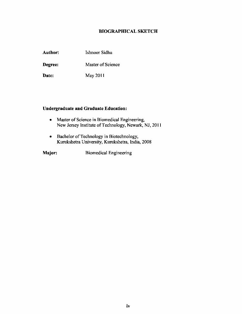
6.2 Neurite Growth in Microchannels
Two types of microchannels were used to plate cells: one with 60 µm and other with 120
µm of channel height. The neurites in the microchannel with 60 µm were growing only in
the reservoir and not in the channels. The neurites follow the wall of the reservoir.
Figure 6.2 Day 20 image of DRG of reservoir 1 in 60 µm high microchannel device.

38
To test whether the channel height was the reason for no neurite growth in the
channels, DRGs were cultured in microchannels with 120 µm height. Figures 6.3, 6.4 and
6.5 show the DRG1 and DRG2 in reservoir 1 and 4 on day 3 and day 12. Few neurites
were seen in the channels on day 12.
Figure 6.3 DRG in microchannels with 120 µm height. (a) DRG1 in reservoir 1 on day
3, (b) DRG2 in reservoir 4 on day 3.
a
b

39
Figure 6.4 DRG 1 in reservoir 1 in microchannels with 120 µm height on day 12.

40
Figure 6.5 DRG 2 in reservoir 4 in microchannels with 120 µm height on day 12.
The neurite growth was not seen in the channels may be due to less amount of
medium or the restriction to grow. Additional research is required to determine the
reason. To enhance the growth of neurites, the culturing was done in open H channels.

41
6.3 Neurite Growth in Open Channels
The DRGs were grown in opposite arms as discussed in Section 5.2.2. Figure 6.6 show
the day 5 culture of two DRGs.
Figure 6.6 Day 5 culture of DRGs in open channels.

42
The neurites in open channels grow faster than the neurites in microchannels. The
reason may be the amount of medium is more and the neurites have no physical barrier
such as wall of reservoir in microchannels.
6.4 Fluidic Isolation
The surface energy present in liquid droplet was exploited to flow the liquids in the
channels without mixing. This was done in microchannels as well as the open channels.
The aim for fluidic exploitation was to determine the volume of liquid droplets and time
required for liquid to flow without mixing.
Figure 6.7 Fluidic isolation in microchannels with 100 µl of water droplets and 5 µl of
green and red inks. (a) after 10 minutes and (b) after 30 minutes.
The droplet of 5 µl flows through the channels. The ink start mixing after 10
minutes and there was complete mixing around 30 minutes. The same experiment was
repeated with larger droplet of 100 µl and smaller droplets of 1µl. Figure 6.8
demonstrates the flow of two liquid without mixing.
a b
43
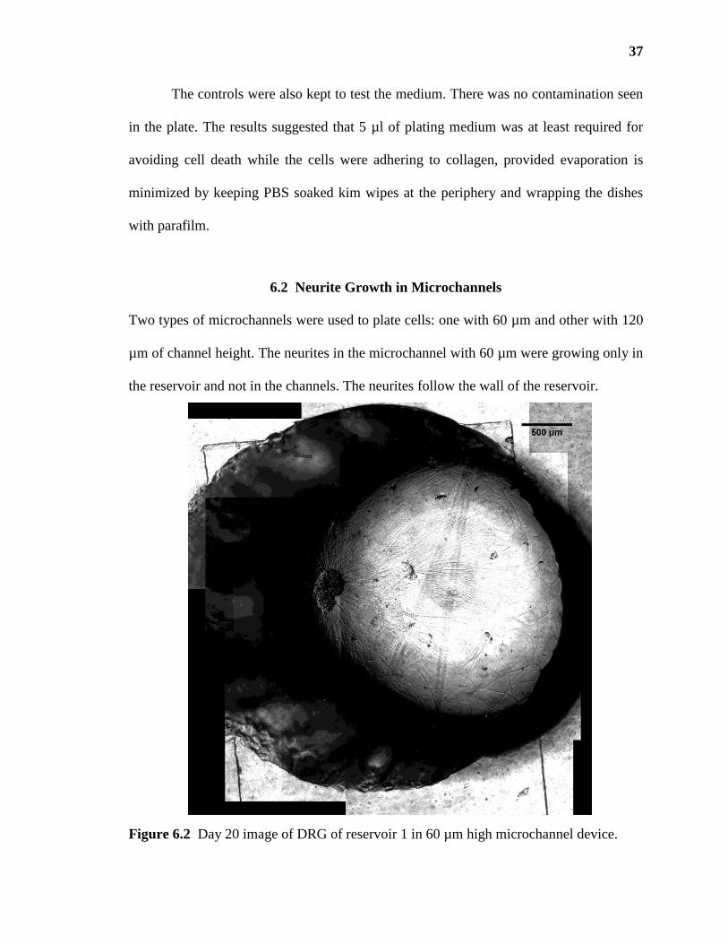
Figure 6.8 Fluidic isolation in microchannels with 100 µl of water droplets and 1µl of
green and red inks after 30 minutes.
The flow was successfully driven by unequal droplets. The pressure presented in
liquid droplet is inversely proportional to the radius of the droplet. The liquid with
smaller radius exert more pressure whereas the pressure exerted by bigger droplet is
negligible. The resulted pressure gradient causes the flow of smaller droplets toward
bigger droplet (Walker & Beebe, 2002).
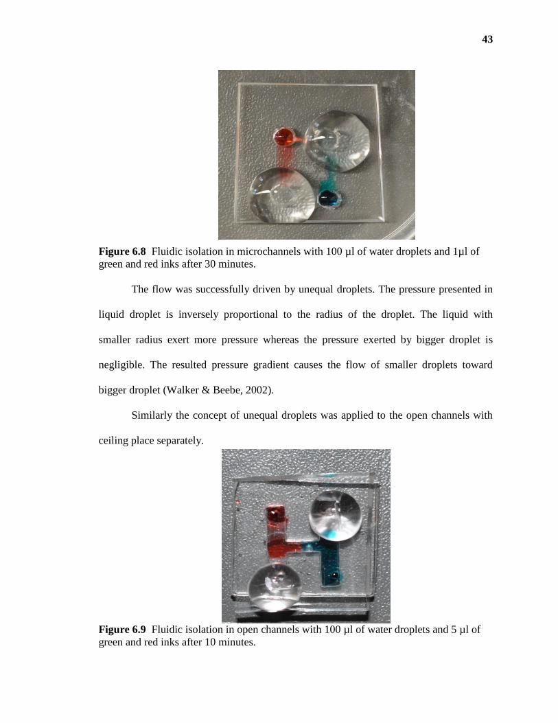
Similarly the concept of unequal droplets was applied to the open channels with
ceiling place separately.
Figure 6.9 Fluidic isolation in open channels with 100 µl of water droplets and 5 µl of
green and red inks after 10 minutes.

44
Figure 6.10 Fluidic isolation in open channels with 100 µl of water droplets and 1µl of
green and red inks after 20 minutes.
The results of fluidic isolation experiments in microchannel suggested that the
smaller droplets of 1 µl can drive the flow towards bigger droplets without mixing for 10-
20 minutes. This experiment demonstrates a simple autonomous method of pumping
liquid in laminar flow without using any external pumping apparatuses.
6.5 Staining of Two DRGs
The results of fluidic isolation were used as a base to stain the two DRGs with two
different dyes (calcein AM and orange cell tracker). Calcein AM is a non-fluorescent dye
that is hydrolyzed by cell intracellular esterases and produce calcein which has
absorbance maxima at 490 nm (blue filter) and maximum emission at 520 nm (green
filter). The orange-fluorescent CellTracker Orange CMRA is a rhodol-based fluorophore
with absorbance and emission maxima at 548 nm (green filter) and 576 nm (orange
filter).

45
The fluorescence microscopy images of two DRGs in open channels are shown in
Figures 6.11 and 6.12
Figure 6.11 DRG1 stained with calcein in open channel arm1.

46
Figure 6.12 DRG2 stained with orange tracker in open channel arm2.

47
The successful staining of the two DRGs was achieved without mixing of stains
both in microchannels and open channels. Calcein stained neurons and neurites images
are sharper than those of orange cell tracker stained neurons. There is much background
seen around the neurons stained with orange cell tracker even after three-four washings.
The fluorescence microscopy images show that the neurons when culture in open
PDMS channels show much faster neurite growth than the microchannels. The neurites in
the microchannels follow the trajectory of the reservoir’s wall. Due to medium volume
difference in reservoir and microchannels, the neurites preferably grow in the reservoirs.
Although the neurites in open channels also follow the trajectory of the “H” walls, the
neurites can be much better seen as growing in all directions.

48
CHAPTER 7
CONCLUSIONS
The presented study demonstrated a simple PDMS device to grow dorsal root ganglion
neurons. Single explants were successfully grown in microchannels and open channels.
However, the growth rate of the neurites differs in the two types of channels due to
difference in volume of maintenance medium and physical barrier for the growth of
neurites in case of closed channels. Although the closed system was not very successful
for the presented study, it could be used to culture the other types of cells that can be
grown in the channels and not in the reservoirs only. Device optimization could be
achieved by growing other type of cells (dissociated DRGs or other smaller cells) in the
channels; thereby the reason for slow and confined growth rate in closed channels could
be identified.
The study also reported a simple self-autonomous method of isolating fluids
exploiting the surface tension of a liquid droplet, as suggested by Walker et al. (Walker &
Beebe, 2002). The method requires no expensive apparatus. This method can be further
exploited to provide the two cells with different environments, as required by any
research.
The simultaneous staining of two DRGs in culture was successfully achieved.
This method is cost effective as compared to the use of transgenic animals. The
simultaneous staining of two DRGs can be further used in distinguishing the two
populations and studying the effect of presence of pioneer neuron on the growth pattern
of the new generation.

49
REFERENCES
Berdichevsky, Y., Staley, K.J. & Yarmush, M.L. (2010) Building and manipulating
neural pathways with microfluidics. Lab on a Chip, 10, 999.
Botzolakis, E.J., Maheshwari, A., Feng, H.J., Lagrange, A.H., Shaver, J.H., Kassebaum,
N.J., Venkataraman, R., Baudenbacher, F. & Macdonald, R.L. (2009) Achieving
synaptically relevant pulses of neurotransmitter using PDMS microfluidics.
Journal of Neuroscience Methods, 177, 294-302.
Burkey, T.H., Hingtgen, C.M. & Vasko, M.R. (2004) Isolation and culture of sensory
neurons from the dorsal-root ganglia of embryonic or adult rats. Methods in
Molecular Medicine, 99, 189-202.
Burns, M.A., Mastrangelo, C.H., Sammarco, T.S., Man, F.P., Webster, J.R., Johnsons, B.,
Foerster, B., Jones, D., Fields, Y. & Kaiser, A.R. (1996) Microfabricated
structures for integrated DNA analysis. Proceedings of the National Academy of
Sciences of the United States of America, 93, 5556.
Chakraborty, S. (2005) Dynamics of capillary flow of blood into a microfluidic channel.
Lab Chip, 5, 421-430.
Cheng, C.M., LeDuc, P.R. & Lin, Y.W. (2011) Localized bimodal response of neurite
extensions and structural proteins in dorsal-root ganglion neurons with controlled
polydimethylsiloxane substrate stiffness. Journal of Biomechanics.
Duffy, D.C., Gillis, H.L., Lin, J., Sheppard Jr, N.F. & Kellogg, G.J. (1999)
Microfabricated centrifugal microfluidic systems: characterization and multiple
enzymatic assays. Analytical chemistry, 71, 4669-4678.
Gross, P., Kartalov, E., Scherer, A. & Weiner, L. (2007) Applications of microfluidics for
neuronal studies. Journal of the Neurological Sciences, 252, 135-143.
Harrison, D.J., Manz, A., Fan, Z., Luedi, H. & Widmer, H.M. (1992) Capillary
electrophoresis and sample injection systems integrated on a planar glass chip.
Analytical chemistry, 64, 1926-1932.
Heuschkel, M.O., Guérin, L., Buisson, B., Bertrand, D. & Renaud, P. (1998) Buried
microchannels in photopolymer for delivering of solutions to neurons in a
network. Sensors and Actuators B: Chemical, 48, 356-361.
http://www.thewellingtonneurosurgeryunit.com/spine-anatomy.asp The Wellington
Hospital - Neurosurgical Unit The Spine.
Jiang, X. & Whitesides, G.M. (2003) Engineering microtools in polymers to study cell
biology. Engineering in life sciences, 3, 475-480.

50
Kandel, E.R., Schwartz, J.H. & Jessell, T.M. (eds) (1991) Principles of Neural Science.
McGraw-Hill.
Kursumovic, M., Sorribes, A. & Zahn, R. Axonal growth on soft lithography fabricated
poly (dimethylsiloxane) structures with different surface coatings.
Lockery, S.R., Lawton, K.J., Doll, J.C., Faumont, S., Coulthard, S.M., Thiele, T.R.,
Chronis, N., McCormick, K.E., Goodman, M.B. & Pruitt, B.L. (2008) Artificial
dirt: Microfluidic substrates for nematode neurobiology and behavior. Journal of
neurophysiology, 99, 3136.
Noback, C.R., Strominger, N.L. & Demarest, R.J. (1996) The Human Nervous System:
Structure and Function. Williams & Wilkins.
Park, J.W., Kim, H.J., Byun, J.H., Ryu, H.R. & Jeon, N.L. (2009) Novel microfluidic
platform for culturing neurons: Culturing and biochemical analysis of neuronal
components. Biotechnology Journal, 4, 1573-1577.
Park, J.W., Vahidi, B., Taylor, A.M., Rhee, S.W. & Jeon, N.L. (2006) Microfluidic
culture platform for neuroscience research. Nature Protocols, 1, 2128-2136.
Pearce, T., Oakes, S., Pope, R. & Williams, J. (Year) Dynamic control of extracellular
environment in in vitro neural recording systems. Vol. 2. IEEE, City. p. 4045-
4048.
Pearce, T.M. & Williams, J.C. (2007) Microtechnology: meet neurobiology. Lab on a
Chip, 7, 30-40.
Perl, E.R. (1992) Function of Dorsal Root Ganglion Neurons: An Overview. In Scott,
S.A. (ed) Sensory Neurons: Diversity, Development, and Plasticity. Oxford
University Press, New York, pp. 3-26.
Shrirao, A.B. & Perez-Castillejos, R. (2010) Simple Fabrication of Microfluidic Devices
by Replicating Scotch-tape Masters. Chips & Tips (Lab on a Chip).
Sia, S.K. & Whitesides, G.M. (2003) Microfluidic devices fabricated in poly
(dimethylsiloxane) for biological studies. Electrophoresis, 24, 3563-3576.
Taylor, A., Rhee, S., Tu, C., Cribbs, D., Cotman, C. & Jeon, N. (2003) Microfluidic
multicomponent device for neuroscience research. Langmuir, 19, 1551–1556.
Taylor, A.M., Blurton-Jones, M., Rhee, S.W., Cribbs, D.H., Cotman, C.W. & Jeon, N.L.
(2005) A microfluidic culture platform for CNS axonal injury, regeneration and
transport. Nature methods, 2, 599-605.

51
Taylor, A.M. & Jeon, N.L. (2010) Micro-scale and microfluidic devices for
neurobiology. Current Opinion in Neurobiology, 20, 640-647.
Taylor, A.M., Rhee, S.W. & Li Jeon, N. (2006) Microfluidic chambers for cell migration
and neuroscience research. Methods in Molecular Biology, 321, 167.
Turner, A., Dowell, N., Turner, S., Kam, L., Isaacson, M., Turner, J., Craighead, H. &
Shain, W. (2000) Attachment of astroglial cells to microfabricated pillar arrays of
different geometries. Journal of biomedical materials research, 51, 430-441.
Unger, M.A., Chou, H.P., Thorsen, T., Scherer, A. & Quake, S.R. (2000) Monolithic
microfabricated valves and pumps by multilayer soft lithography. Science, 288,
113.
Walker, G.M. & Beebe, D.J. (2002) A passive pumping method for microfluidic devices.
Lab on a Chip, 2, 131-134.
Wang, J., Ren, L., Li, L., Liu, W., Zhou, J., Yu, W., Tong, D. & Chen, S. (2009)
Microfluidics: A new cosset for neurobiology. Lab on a Chip, 9, 644.
Whitesides, G.M. (2006) The origins and the future of microfluidics. Nature, 442, 368-
373.
Xia, Y. & Whitesides, G.M. (1998) Soft Lithography. Annual Review of Materials
Science, 28, 153-184.