Embed Size (px)
Citation preview
UNIVERSITI TUN HUSSEIN ONN MALAYSIA Faculty of Mechanical and Manufacturing Engineering
__________________________________________________________________
BDA 27201 - Edition III/2011 1
COURSE INFORMATION
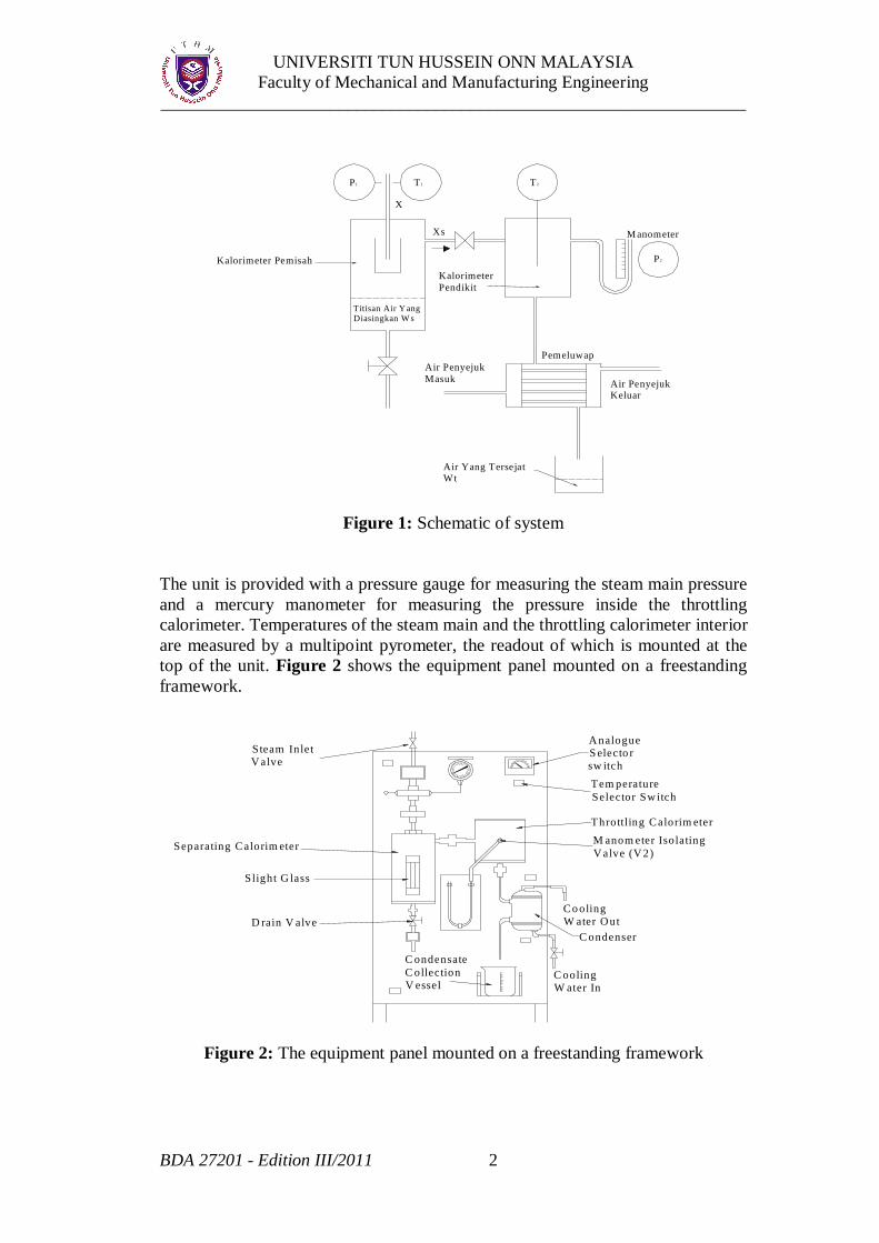
COURSE TITLE: ENGINEERING LABORATORY IV (BDA 27201) TOPIC : SEPARATING AND THROTTLING CALORIMETER 1. INTRODUCTION Separating and throttling calorimeter are used to determine the dryness fraction of steam. In this experiment, the combination of these two calorimeters is used to determine the dryness fraction of the steam supplied to the system. The separating calorimeter is a mechanical process in which the incoming wet steam is made to change direction through a series of obtuse angle. As the steam travels through this angle, the inertia of the water droplets prevents them from following the changes in direction of the steam and causes them to drop out of the steam into the collection chamber. In the throttling calorimeter, the incoming steam is fed into the throttling calorimeter body via a fixed orifice, the pressure inside the calorimeter body being slightly above atmospheric. This causes the steam to become superheated and by measuring the final temperature and pressure this steam, the dryness fraction of the steam can be calculated. However, both these types of calorimeters have shortcoming. The separating calorimeter cannot separate out all of the water and some is carried over with the dry steam. The throttling calorimeter relies on the steam being throttled into the superheat region, which is not possible if the steam is too wet before throttling. The solution to these problems is to combine the two types of calorimeter by connecting them in series; the separating calorimeter being nearest to the incoming main. The schematic of the separating and throttling calorimeter is shown in Figure 1 and they are mounted physically on a freestanding unit with integral instrumentation.
UNIVERSITI TUN HUSSEIN ONN MALAYSIA Faculty of Mechanical and Manufacturing Engineering
__________________________________________________________________
BDA 27201 - Edition III/2011 2
Figure 1: Schematic of system
The unit is provided with a pressure gauge for measuring the steam main pressure and a mercury manometer for measuring the pressure inside the throttling calorimeter. Temperatures of the steam main and the throttling calorimeter interior are measured by a multipoint pyrometer, the readout of which is mounted at the top of the unit. Figure 2 shows the equipment panel mounted on a freestanding framework.
Figure 2: The equipment panel mounted on a freestanding framework
P1
X
Xs
T1 T2
M anometer
P2
Titisan Air Yang Diasingkan W s
Kalorimeter Pemisah
Air Penyejuk Masuk Air Penyejuk
Keluar
Kalorimeter Pendikit
Pemeluwap
Air Yang Tersejat Wt
Steam Inlet V alve
A nalogue S electo r sw itchTem perature Selector Sw itch
Throttling Calorim eterM anom eter Isolating V alve (V 2)Separating Calorim eter
Slight G lass
C ondenser
C ooling W ater In
D rain V alveCo oling W ater O ut
C ondensate C ollection V essel
UNIVERSITI TUN HUSSEIN ONN MALAYSIA Faculty of Mechanical and Manufacturing Engineering
__________________________________________________________________
BDA 27201 - Edition III/2011 3
2. OBJECTIVES To determine the dryness fraction of steam 3. LEARNING OUTCOMES At the end of this experiment, students should be able to:
a. Understand the concepts of dryness fraction b. Implement and analyze the required data collectively within
member of group. c. Produce good technical report according to the required
standard 4. THEORY The following are the relevant theories pertaining to the experiment
Dryness Fraction The dryness fraction is defined as the quantity of dry vapour present in any wet vapour mixture.
water steamdry ofQuantity
steamdry ofQuantity fraction Dryness
Separating Calorimeter
This is a mechanical process where the incoming steam to the calorimeter is made through a series of obtuse angle where the inertia of the water droplets causes them to separate from steam flow. If
tW = quantity of dry steam discharged from calorimeter
sW = quantity of water separated in the calorimeter in the same time interval;
then the dryness fraction as measured by the separating calorimeter (Xs)
sts WW
tWX
(1)
UNIVERSITI TUN HUSSEIN ONN MALAYSIA Faculty of Mechanical and Manufacturing Engineering
__________________________________________________________________
BDA 27201 - Edition III/2011 4
Throttling Calorimeter
Consider a fluid flowing through a throttling orifice from higher pressure P1 to a lower pressure P2. From the steady flow energy equation, it can be shown that adiabatic throttling is a constant enthalpy process. The wet steam before the throttling will become superheated steam at the lower pressure after throttling. Enthalpy of wet steam at P1 before throttling;
111 fgtf h XhH
where
1fh = specific enthalpy of saturated liquid (sensible heat) corresponding to pressure P1
tX = dryness fraction of steam measured by throttling calorimeter
1fgh = specific enthalpy of vaporisation (latent heat) corresponding to
pressure P1 Enthalpy of superheated steam at P2 after throttling
2222 spg tt ChH
where
2gh = specific enthalpy at saturated vapour corresponding to pressure P2
pC = specific heat at constant pressure
2t = steam temperature at throttling calorimeter
2st = saturated steam temperature corresponding to pressure P2
Since 21 HH ,
22211 spgfgtf tt Chh Xh
1
1222 )(
fg
fspg
hhttch
Xt
(2)
UNIVERSITI TUN HUSSEIN ONN MALAYSIA Faculty of Mechanical and Manufacturing Engineering
__________________________________________________________________
BDA 27201 - Edition III/2011 5
Combined Separating and Throttling
If w = quantity of water in steam leaving the separating calorimeter and entering the throttling calorimeter, then by definition of dryness fraction
t
tt W
wWX and )1( tt XWw
But the separating calorimeter has already removed Ws water, therefore total quantity of water is (Ws + w) in wet steam ts WW Applying this to the definition of dryness fraction
ts
sts
WWwWWWX
ts
t
WWwW
but )1( tt XWw
ts
ttt
WWXWW
)1(
tts
t XWW
W x
From equation (1) st
s WWtW
X
Therefore: True dryness fraction,
ts XXX x (3)
UNIVERSITI TUN HUSSEIN ONN MALAYSIA Faculty of Mechanical and Manufacturing Engineering
__________________________________________________________________
BDA 27201 - Edition III/2011 6
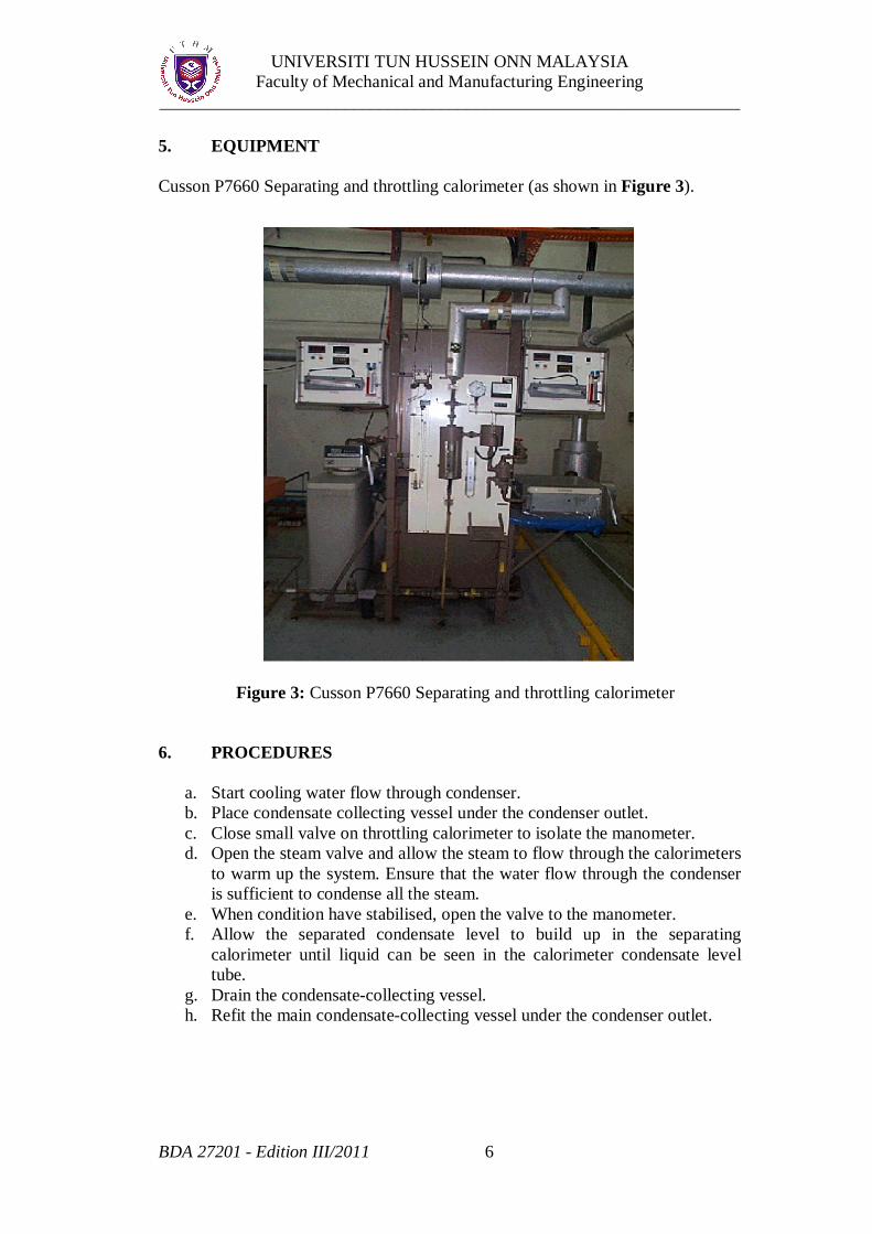
5. EQUIPMENT Cusson P7660 Separating and throttling calorimeter (as shown in Figure 3).
6. PROCEDURES
a. Start cooling water flow through condenser. b. Place condensate collecting vessel under the condenser outlet. c. Close small valve on throttling calorimeter to isolate the manometer. d. Open the steam valve and allow the steam to flow through the calorimeters
to warm up the system. Ensure that the water flow through the condenser is sufficient to condense all the steam.
e. When condition have stabilised, open the valve to the manometer. f. Allow the separated condensate level to build up in the separating
calorimeter until liquid can be seen in the calorimeter condensate level tube.
g. Drain the condensate-collecting vessel. h. Refit the main condensate-collecting vessel under the condenser outlet.
Figure 3: Cusson P7660 Separating and throttling calorimeter
UNIVERSITI TUN HUSSEIN ONN MALAYSIA Faculty of Mechanical and Manufacturing Engineering
__________________________________________________________________
BDA 27201 - Edition III/2011 7
i. Measure and record:
a. Initial value of fluid level in the separating calorimeter. b. Initial value of condense level in the main condensate-
collecting vessel. c. The steam pressure in the steam main. d. The steam pressure after throttling. e. Steam main steam temperature. f. Temperature in the throttling calorimeter. g. Barometric pressure.
The value from (c) to (f) parameter values should be checked about six times during the course of measurement.
j. Allow the apparatus to cool and turn off the condenser cooling water. k. Drain the separating calorimeter. l. Empty the condensate-collecting vessel.
7. EXPERIMENT DATA
Refer to the data sheet provided in Appendix A.
8. RESULT AND DISCUSSION
a. Complete the data sheet provided in Appendix A. b. Calculate the dryness fraction for the steam after flow through the
separator, Xs and throttle, Xt. c. Give suggestion on the overall performance of steam line based on the true
dryness fraction, X obtained.
9. QUESTIONS
a. Explain the importance of the dryness fraction value for a steam power
plant in terms of safety and economic. b. Define the overall processes of steam power plant in obtaining the
practical and effective dryness fraction.
10. CONCLUSION
Deduce conclusions from the experiment. Please comment on your experimental work in terms of achievement, problems faced throughout the experiment and suggest recommendation for improvements.
UNIVERSITI TUN HUSSEIN ONN MALAYSIA Faculty of Mechanical and Manufacturing Engineering
__________________________________________________________________
BDA 27201 - Edition III/2011 8
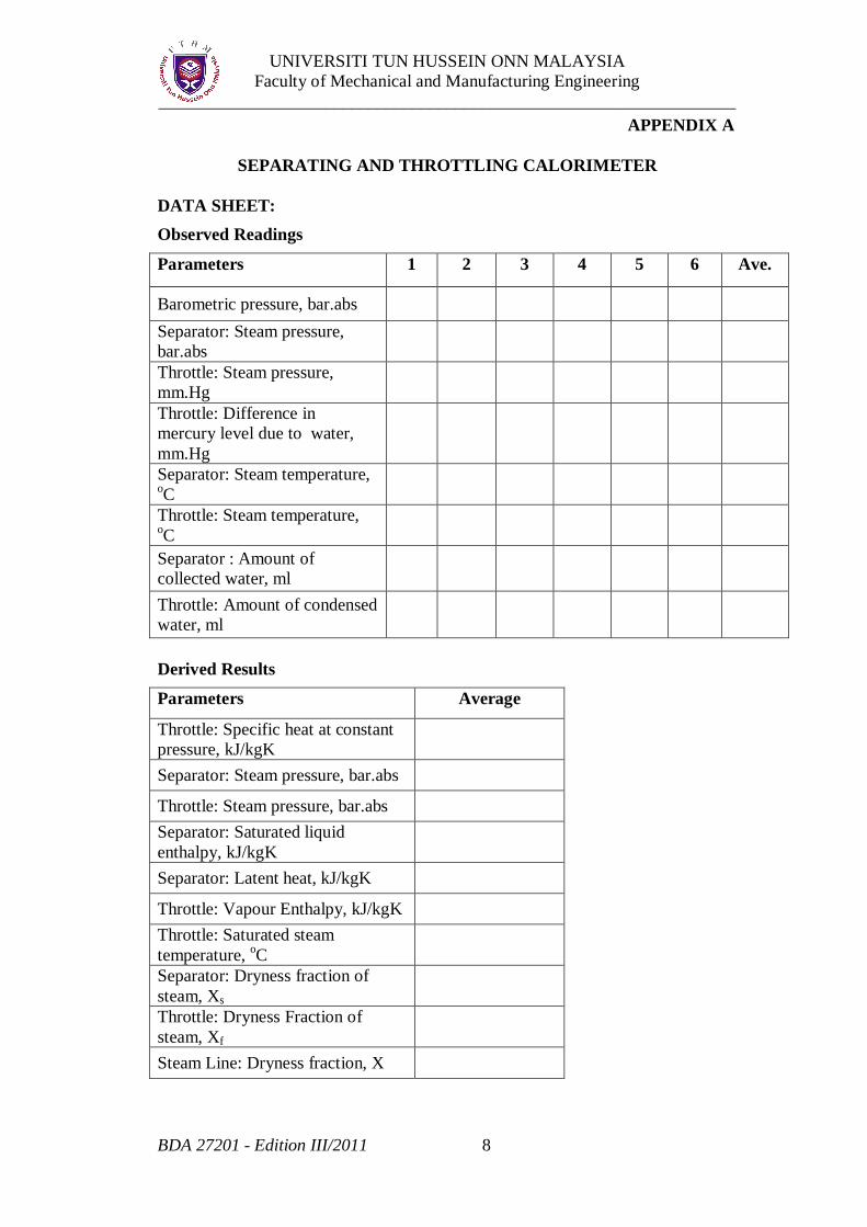
APPENDIX A
SEPARATING AND THROTTLING CALORIMETER
DATA SHEET: Observed Readings
Parameters 1 2 3 4 5 6 Ave.
Barometric pressure, bar.abs
Separator: Steam pressure, bar.abs
Throttle: Steam pressure, mm.Hg
Throttle: Difference in mercury level due to water, mm.Hg
Separator: Steam temperature, oC
Throttle: Steam temperature, oC
Separator : Amount of collected water, ml
Throttle: Amount of condensed water, ml
Derived Results
Parameters Average
Throttle: Specific heat at constant pressure, kJ/kgK
Separator: Steam pressure, bar.abs
Throttle: Steam pressure, bar.abs
Separator: Saturated liquid enthalpy, kJ/kgK
Separator: Latent heat, kJ/kgK
Throttle: Vapour Enthalpy, kJ/kgK
Throttle: Saturated steam temperature, oC
Separator: Dryness fraction of steam, Xs
Throttle: Dryness Fraction of steam, Xf
Steam Line: Dryness fraction, X