Embed Size (px)
Citation preview
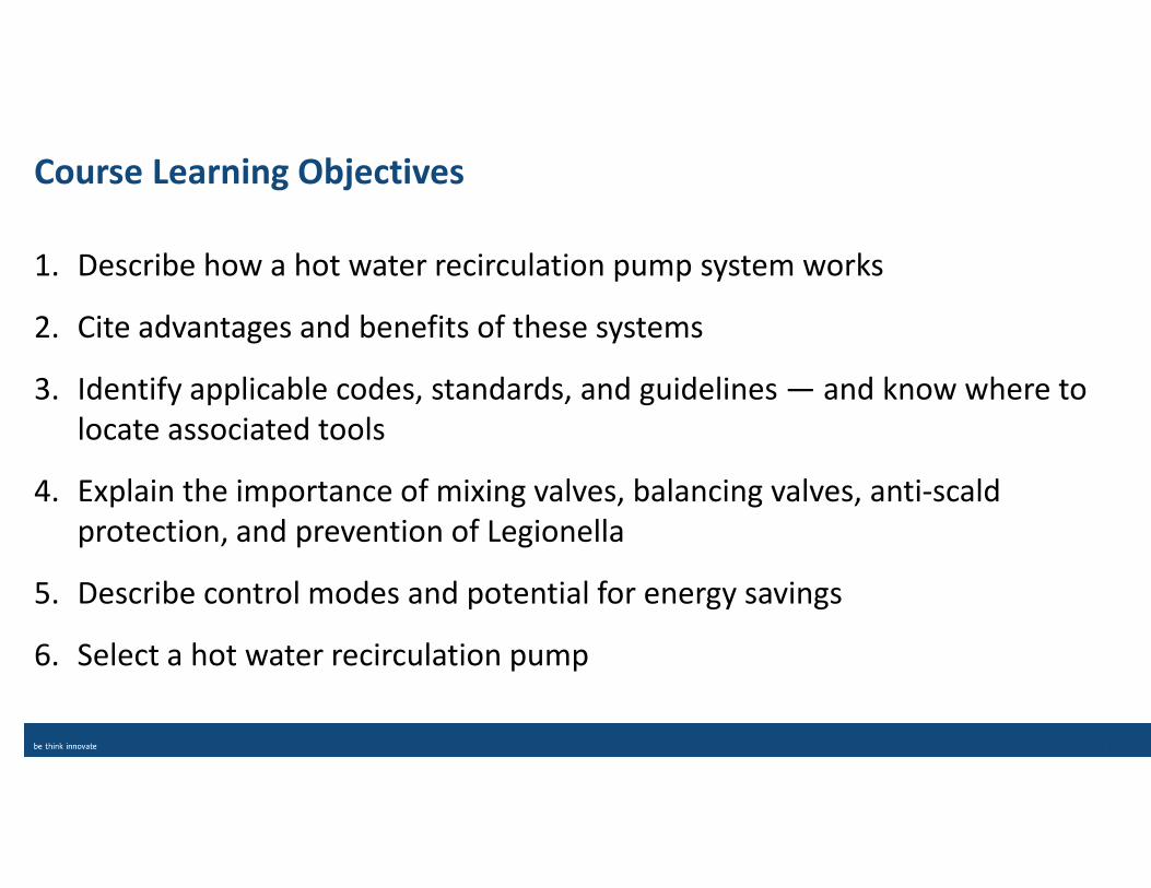
Course Learning Objectives
1. Describe how a hot water recirculation pump system works
2. Cite advantages and benefits of these systems
3. Identify applicable codes, standards, and guidelines — and know where to
locate associated tools
4. Explain the importance of mixing valves, balancing valves, anti-scald
protection, and prevention of Legionella
5. Describe control modes and potential for energy savings
6. Select a hot water recirculation pump
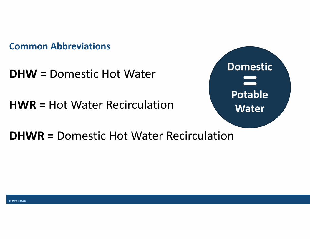
Common Abbreviations
DHW = Domestic Hot Water
HWR = Hot Water Recirculation
DHWR = Domestic Hot Water Recirculation
Domestic
Potable
Water
=
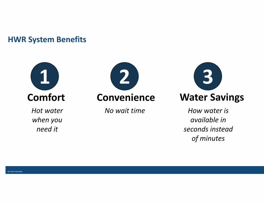
HWR System Benefits
Comfort Convenience Water Savings
1 2 3
Hot water
when you
need it
No wait time How water is
available in
seconds instead
of minutes
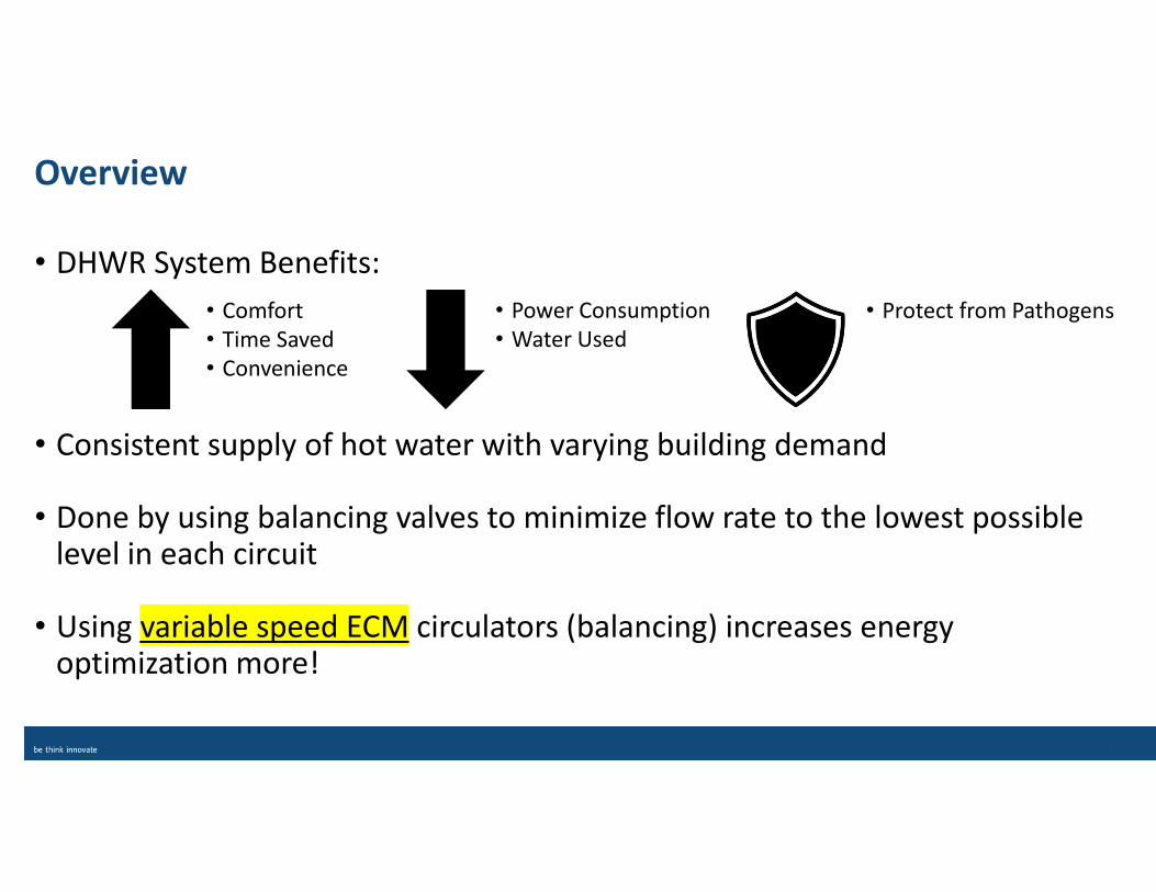
Overview
• DHWR System Benefits:
• Consistent supply of hot water with varying building demand
• Done by using balancing valves to minimize flow rate to the lowest possible level in each circuit
• Using variable speed ECM circulators (balancing) increases energy optimization more!
• Comfort
• Time Saved
• Convenience
• Power Consumption
• Water Used
• Protect from Pathogens
Proper Installation is Imperative for …
1. Ensuring rapid delivery of hot water to all fixtures upon demand
2. Reducing water waste
3. Assuring that the water temperature is safe (non-scalding)
4. Preventing growth of Legionella and other pathogens
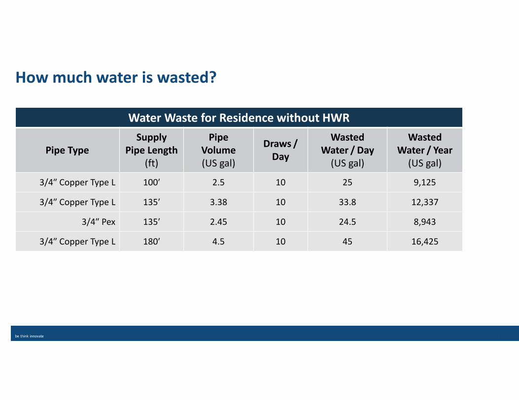
How much water is wasted?
Water Waste for Residence without HWR
Pipe Type
Supply
Pipe Length
(ft)
Pipe
Volume
(US gal)
Draws /
Day
Wasted
Water / Day
(US gal)
Wasted
Water / Year
(US gal)
3/4″ Copper Type L 100′ 2.5 10 25 9,125
3/4″ Copper Type L 135′ 3.38 10 33.8 12,337
3/4″ Pex 135′ 2.45 10 24.5 8,943
3/4″ Copper Type L 180′ 4.5 10 45 16,425
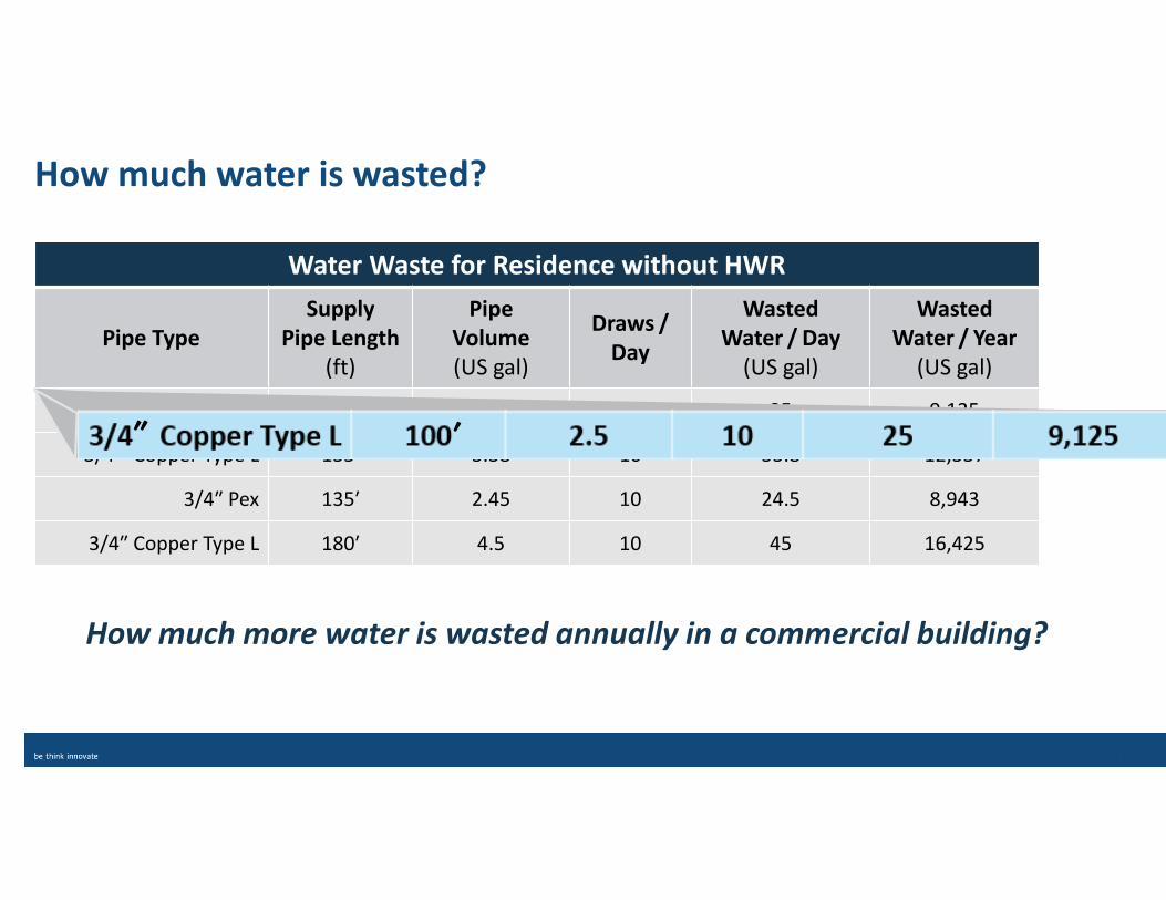
How much water is wasted?
Water Waste for Residence without HWR
Pipe Type
Supply
Pipe Length
(ft)
Pipe
Volume
(US gal)
Draws /
Day
Wasted
Water / Day
(US gal)
Wasted
Water / Year
(US gal)
3/4 ″ Copper Type L 100′ 2.5 10 25 9,125
3/4 ″ Copper Type L 135′ 3.38 10 33.8 12,337
3/4″ Pex 135′ 2.45 10 24.5 8,943
3/4″ Copper Type L 180′ 4.5 10 45 16,425
How much more water is wasted annually in a commercial building?
′″
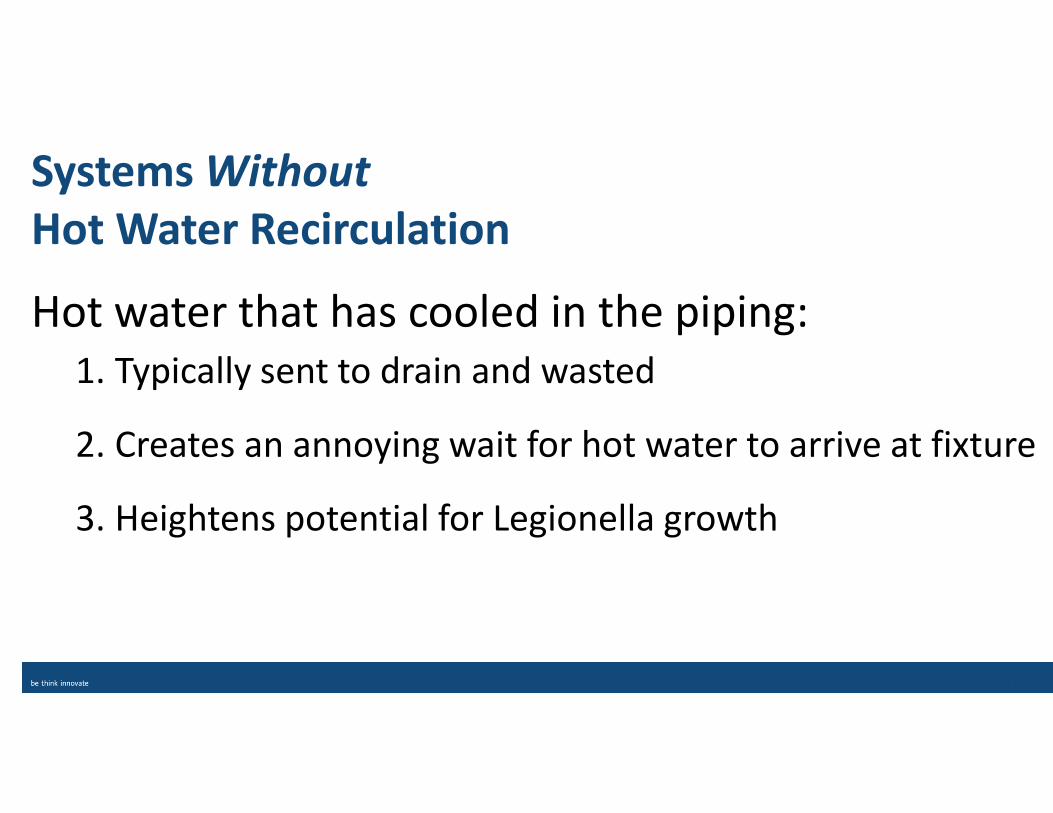
Systems Without
Hot Water Recirculation
Hot water that has cooled in the piping:
1. Typically sent to drain and wasted
2. Creates an annoying wait for hot water to arrive at fixture
3. Heightens potential for Legionella growth
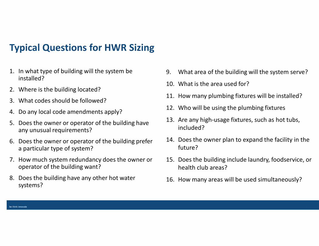
9. What area of the building will the system serve?
10. What is the area used for?
11. How many plumbing fixtures will be installed?
12. Who will be using the plumbing fixtures
13. Are any high-usage fixtures, such as hot tubs,
included?
14. Does the owner plan to expand the facility in the
future?
15. Does the building include laundry, foodservice, or
health club areas?
16. How many areas will be used simultaneously?
1. In what type of building will the system be installed?
2. Where is the building located?
3. What codes should be followed?
4. Do any local code amendments apply?
5. Does the owner or operator of the building have any unusual requirements?
6. Does the owner or operator of the building prefer a particular type of system?
7. How much system redundancy does the owner or operator of the building want?
8. Does the building have any other hot water systems?
Typical Questions for HWR Sizing
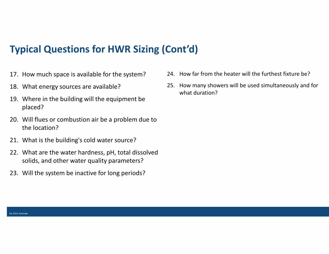
24. How far from the heater will the furthest fixture be?
25. How many showers will be used simultaneously and for
what duration?
17. How much space is available for the system?
18. What energy sources are available?
19. Where in the building will the equipment be
placed?
20. Will flues or combustion air be a problem due to
the location?
21. What is the building's cold water source?
22. What are the water hardness, pH, total dissolved
solids, and other water quality parameters?
23. Will the system be inactive for long periods?
Typical Questions for HWR Sizing (Cont’d)
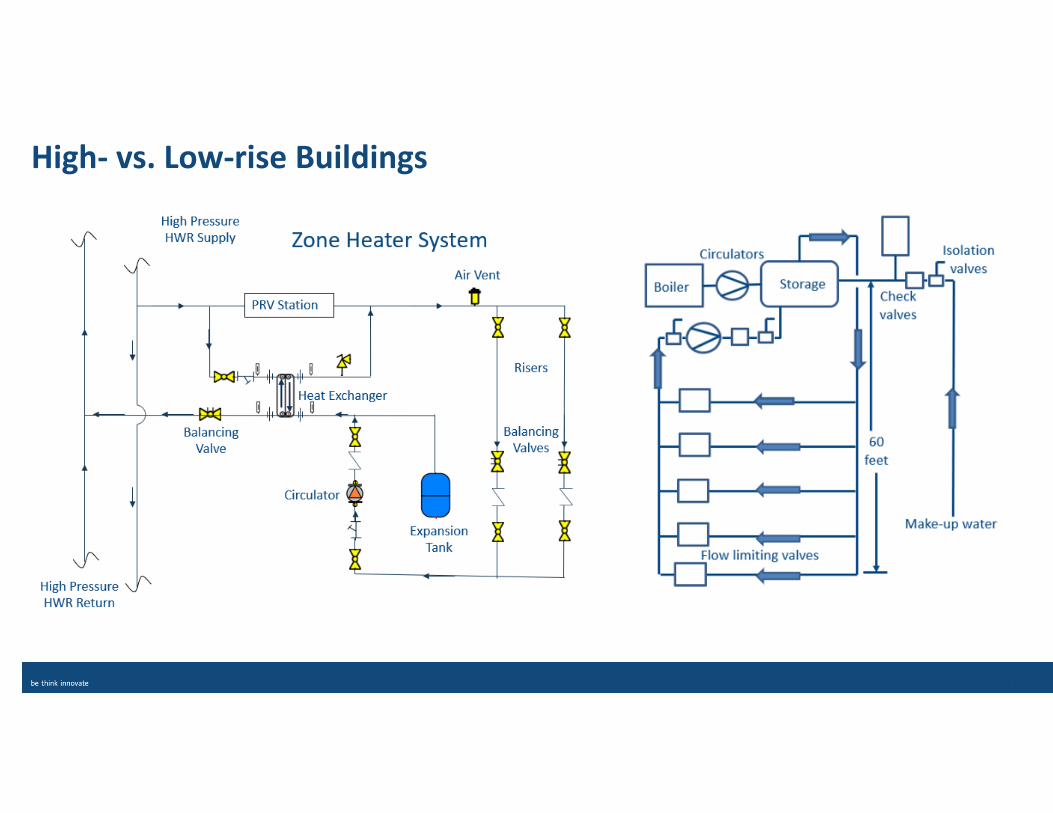
High- vs. Low-rise Buildings
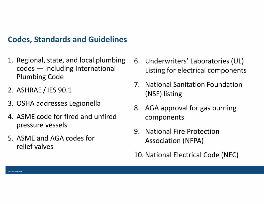
6. Underwriters’ Laboratories (UL)
Listing for electrical components
7. National Sanitation Foundation
(NSF) listing
8. AGA approval for gas burning
components
9. National Fire Protection
Association (NFPA)
10. National Electrical Code (NEC)
1. Regional, state, and local plumbing codes — including International Plumbing Code
2. ASHRAE / IES 90.1
3. OSHA addresses Legionella
4. ASME code for fired and unfired pressure vessels
5. ASME and AGA codes for relief valves
Codes, Standards and Guidelines
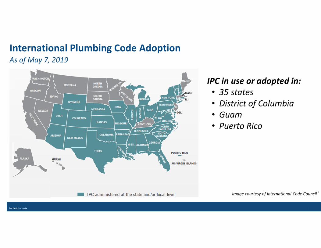
International Plumbing Code AdoptionAs of May 7, 2019
Image courtesy of International Code Council®
IPC in use or adopted in:
• 35 states
• District of Columbia
• Guam
• Puerto Rico
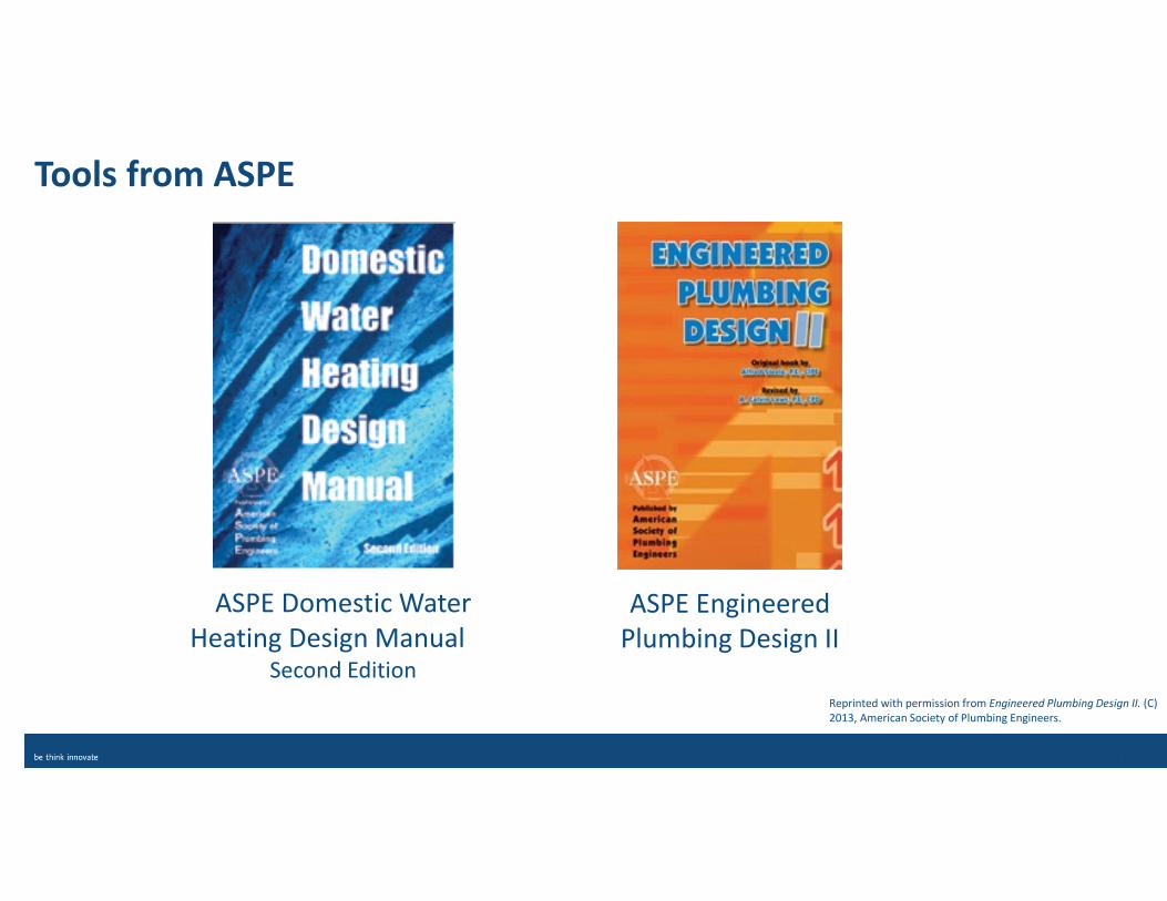
Tools from ASPE
ASPE Domestic Water
Heating Design Manual Second Edition
ASPE Engineered
Plumbing Design II
Reprinted with permission from Engineered Plumbing Design II. (C)
2013, American Society of Plumbing Engineers.
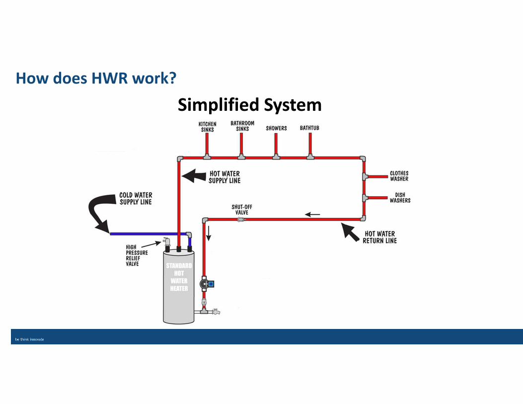
How does HWR work?
Simplified System
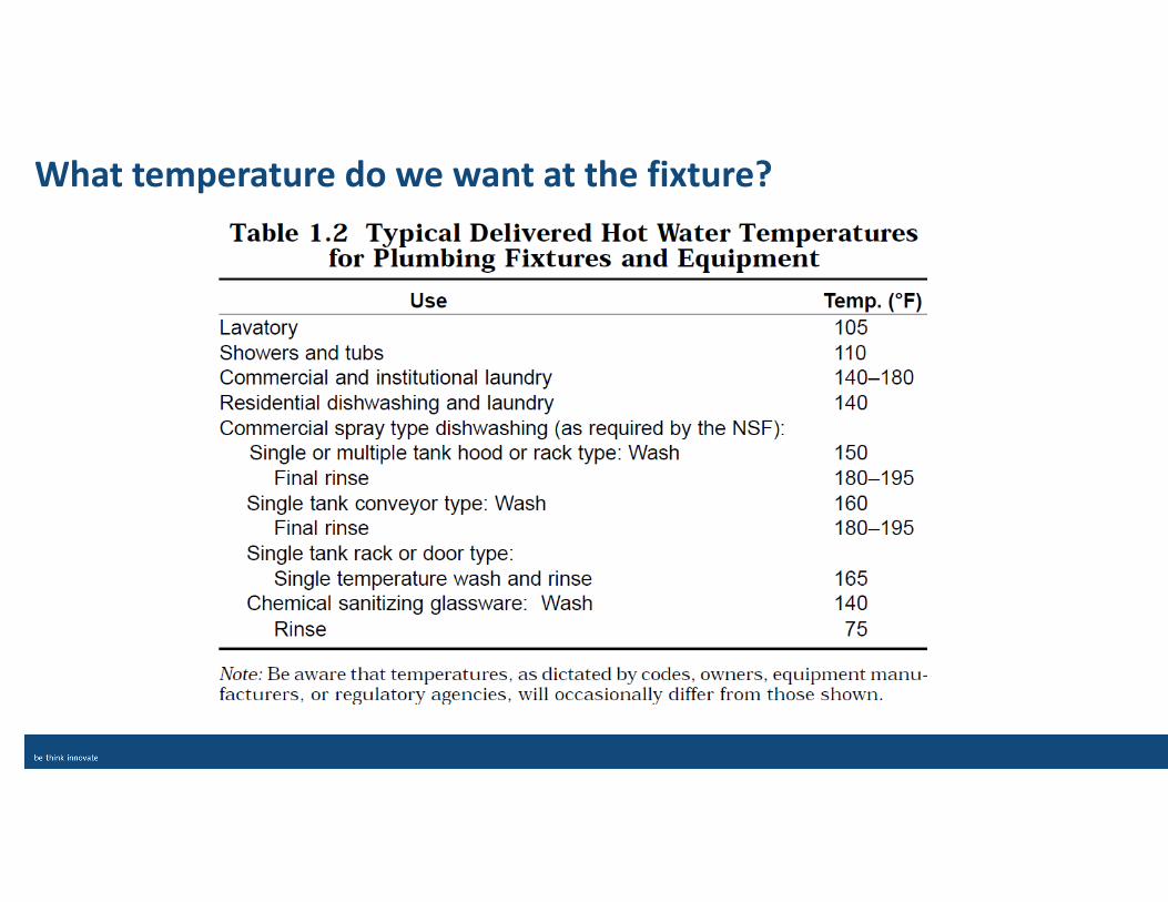
What temperature do we want at the fixture?
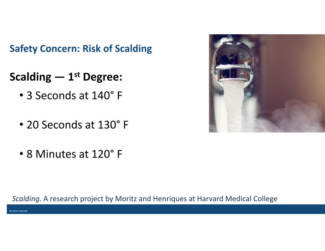
Scalding — 1st Degree:
• 3 Seconds at 140° F
• 20 Seconds at 130° F
• 8 Minutes at 120° F
Safety Concern: Risk of Scalding
Scalding. A research project by Moritz and Henriques at Harvard Medical College

Safety Concern: Legionella
• Legionella Pneumophila (Legionnaires’ Disease)
• Temperature range for bacteria growth varies across organizations
and the country:
• Centers for Disease Control and Prevention (CDC): 90–113° F
• ASHRAE: 77–108° F
• Legionella Control in Healthcare Facilities: 68–122° F (ideal = 95–115° F)
• American Society for Healthcare Engineering & Joint Commission list: 77–108° F
• Combined ranges of 68–122° F may survive municipal water treatment
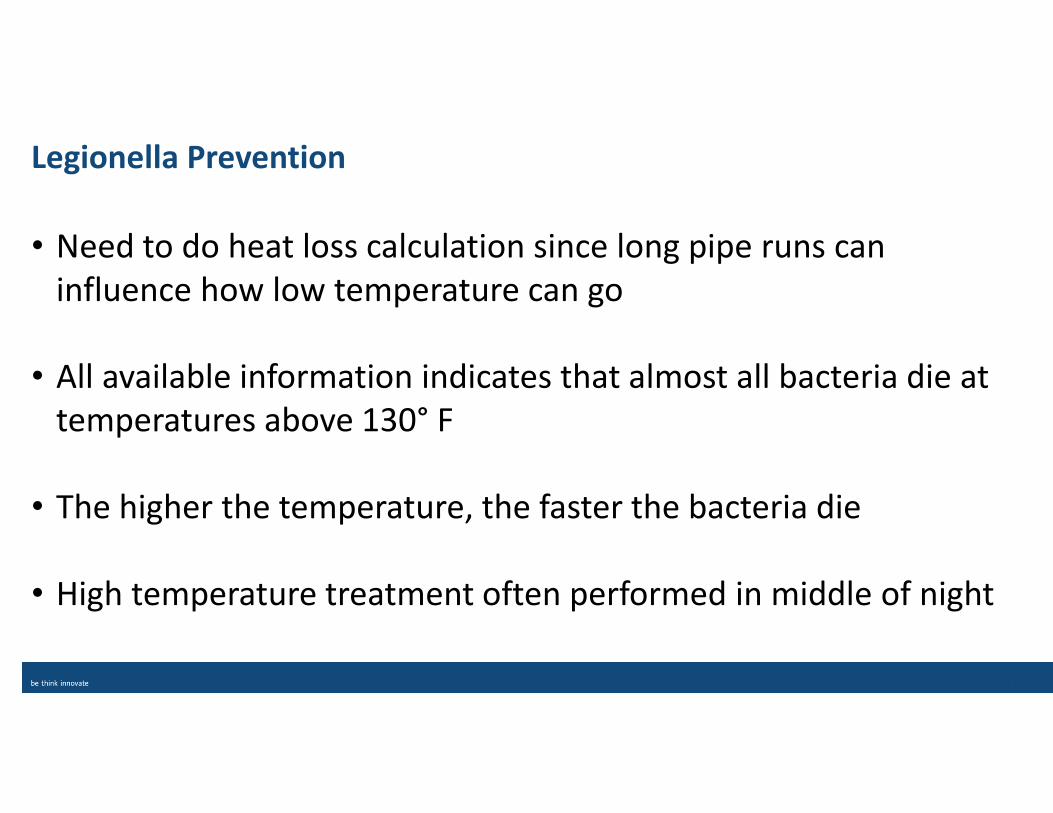
Legionella Prevention
• Need to do heat loss calculation since long pipe runs can
influence how low temperature can go
• All available information indicates that almost all bacteria die at
temperatures above 130° F
• The higher the temperature, the faster the bacteria die
• High temperature treatment often performed in middle of night
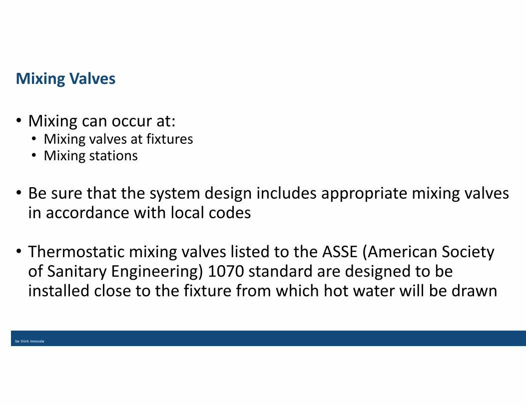
Mixing Valves
• Mixing can occur at: • Mixing valves at fixtures • Mixing stations
• Be sure that the system design includes appropriate mixing valves in accordance with local codes
• Thermostatic mixing valves listed to the ASSE (American Society of Sanitary Engineering) 1070 standard are designed to be installed close to the fixture from which hot water will be drawn
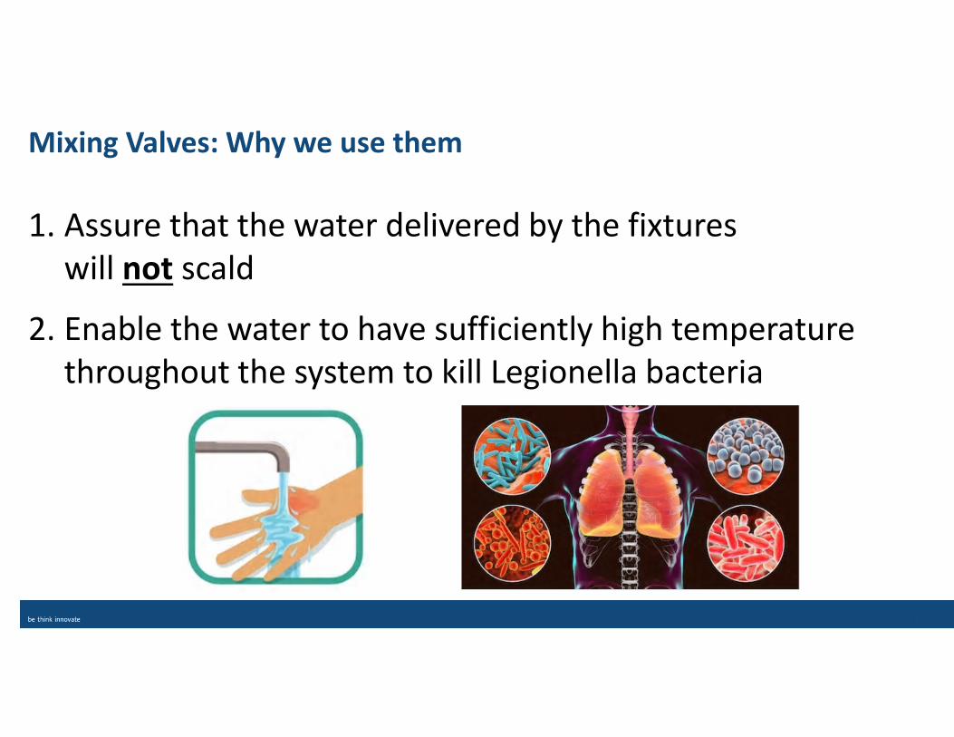
Mixing Valves: Why we use them
1. Assure that the water delivered by the fixtures
will not scald
2. Enable the water to have sufficiently high temperature
throughout the system to kill Legionella bacteria
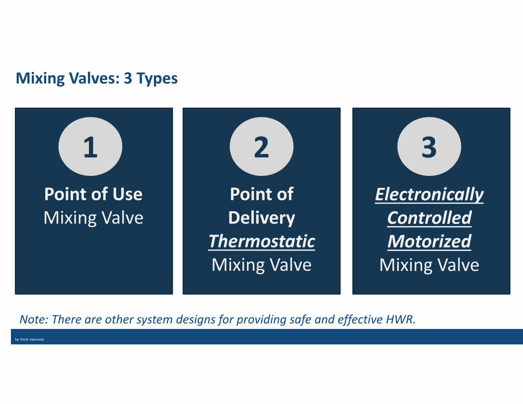
Mixing Valves: 3 Types
1
Point of Use
Mixing Valve
2
Point of
Delivery
Thermostatic
Mixing Valve
3
Electronically
Controlled
Motorized
Mixing Valve
Note: There are other system designs for providing safe and effective HWR.
Why System Balance is a MUST!
• Multiple piping risers; numbers of fixtures;
varying elevations
• Differing circuit lengths and fixtures quantities
• Unbalanced circuits create inappropriate
temperature drops and inadequate temperatures at some fixtures
• Use of only one circulator can be problematic
• Balancing creates a common temperature drop between the start and stop
of each circuit
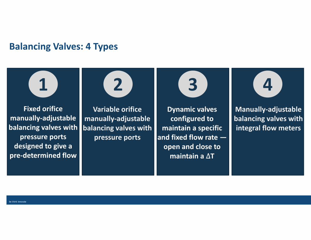
Balancing Valves: 4 Types
1Fixed orifice
manually-adjustable
balancing valves with
pressure ports
designed to give a
pre-determined flow
2Variable orifice
manually-adjustable
balancing valves with
pressure ports
3Dynamic valves
configured to
maintain a specific
and fixed flow rate —
open and close to
maintain a ΔT
4Manually-adjustable
balancing valves with
integral flow meters
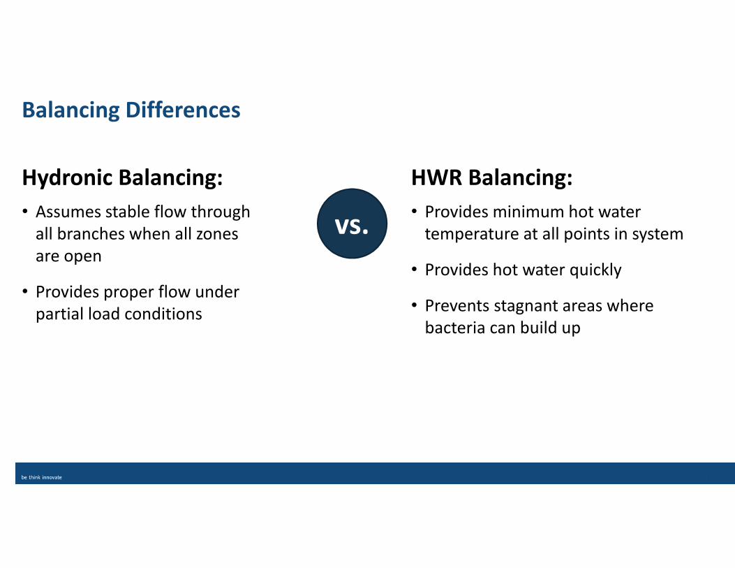
Balancing Differences
• Provides minimum hot water
temperature at all points in system
• Provides hot water quickly
• Prevents stagnant areas where
bacteria can build up
• Assumes stable flow through
all branches when all zones
are open
• Provides proper flow under
partial load conditions
Hydronic Balancing: HWR Balancing:
vs.
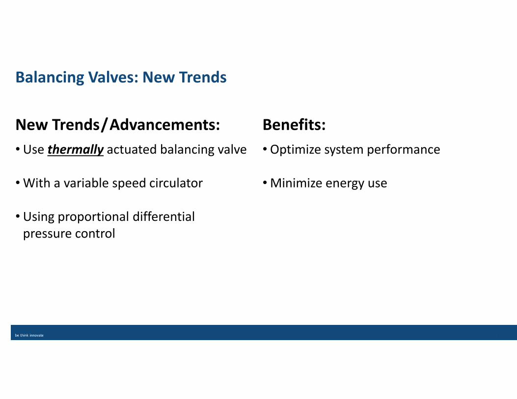
Balancing Valves: New Trends
•Optimize system performance
•Minimize energy use
•Use thermally actuated balancing valve
•With a variable speed circulator
•Using proportional differential
pressure control
New Trends/Advancements: Benefits:
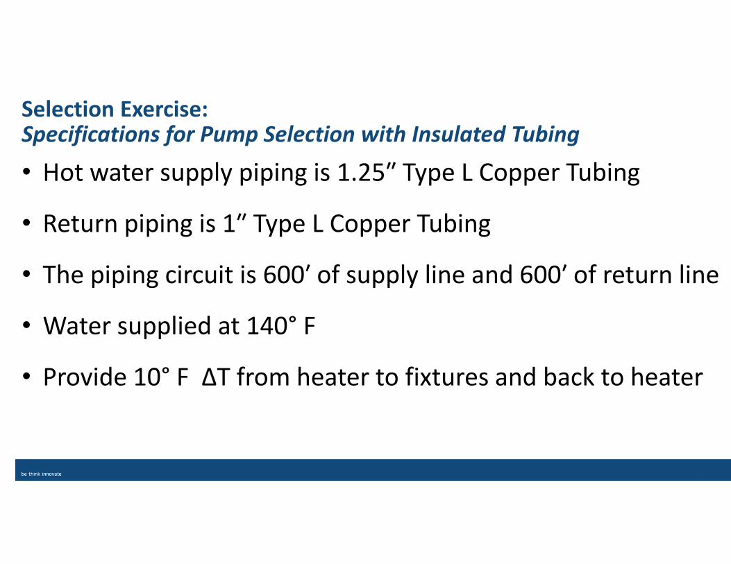
Selection Exercise: Specifications for Pump Selection with Insulated Tubing
• Hot water supply piping is 1.25″ Type L Copper Tubing
• Return piping is 1″ Type L Copper Tubing
• The piping circuit is 600′ of supply line and 600′ of return line
• Water supplied at 140° F
• Provide 10° F ΔT from heater to fixtures and back to heater
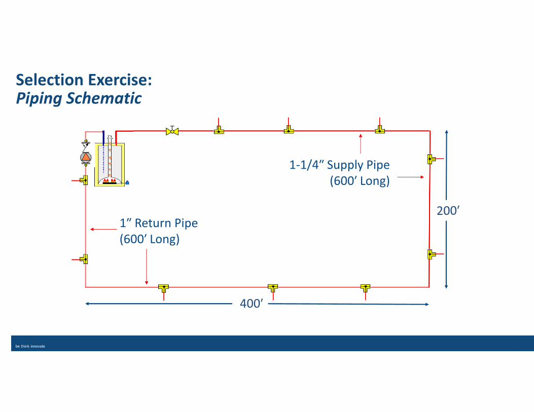
400′
1-1/4″ Supply Pipe
(600′ Long)
1″ Return Pipe
(600′ Long)
Selection Exercise: Piping Schematic
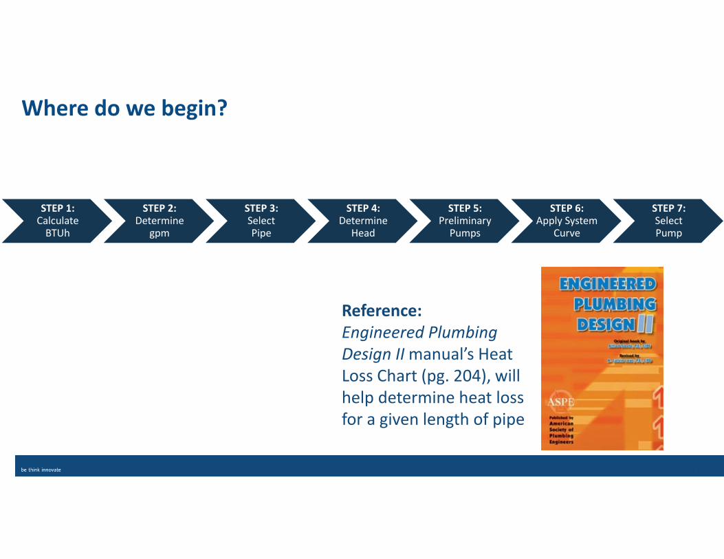
Where do we begin?
STEP 1:Calculate
BTUh
STEP 2: Determine
gpm
STEP 3: Select Pipe
STEP 4: Determine
Head
STEP 5: Preliminary
Pumps
STEP 6: Apply System
Curve
STEP 7:Select Pump
Reference:
Engineered Plumbing
Design II manual’s Heat
Loss Chart (pg. 204), will
help determine heat loss
for a given length of pipe
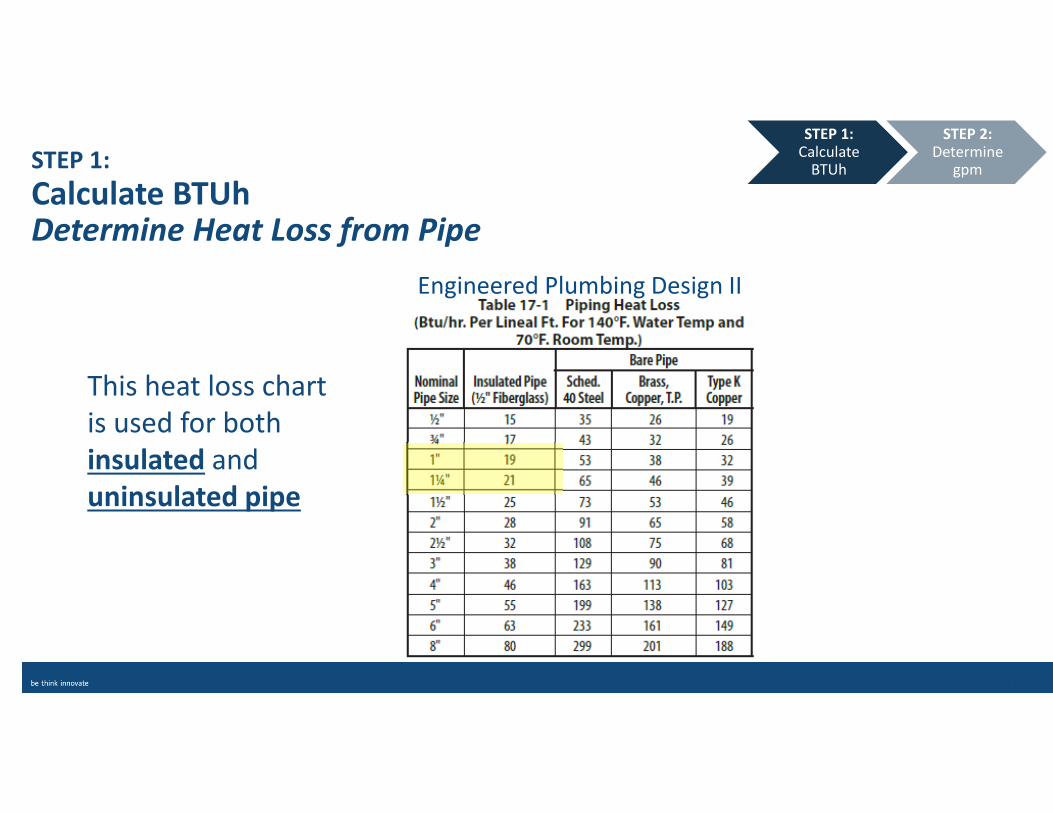
STEP 1:Calculate
BTUh
This heat loss chart
is used for both
insulated and
uninsulated pipe
Engineered Plumbing Design II
STEP 2: Determine
gpmSTEP 1:
Calculate BTUhDetermine Heat Loss from Pipe
STEP 1:
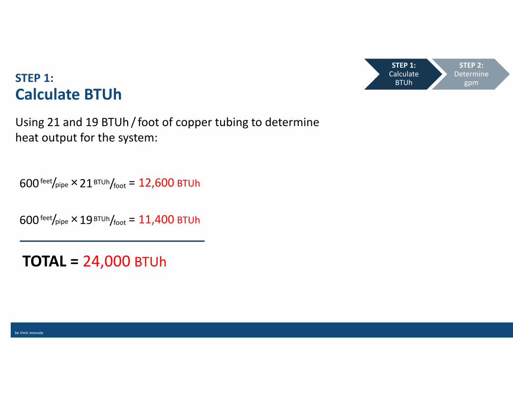
Calculate BTUh
Using 21 and 19 BTUh / foot of copper tubing to determine
heat output for the system:
STEP 1:Calculate
BTUh
STEP 2: Determine
gpm
TOTAL = 24,000 BTUh
600 feet/pipe × 19BTUh/foot = 11,400 BTUh
600 feet/pipe × 21BTUh/foot = 12,600 BTUh
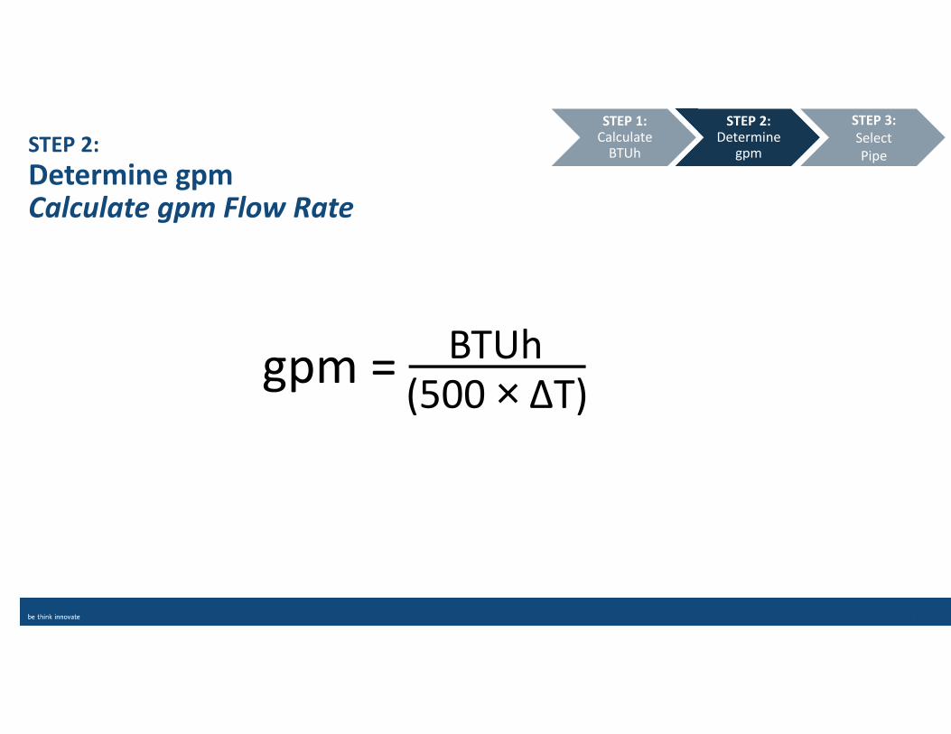
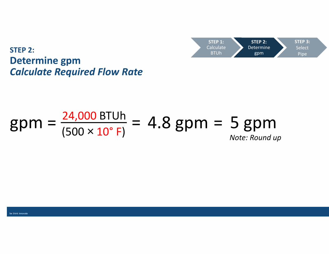
STEP 2:
Determine gpmCalculate gpm Flow Rate
gpm =
STEP 2: Determine
gpm
STEP 3:
Select
Pipe
STEP 1: Calculate
BTUh
BTUh
(500 × ΔT)
STEP 2:
Determine gpmCalculate Required Flow Rate
STEP 2: Determine
gpm
STEP 3:
Select
Pipe
STEP 1: Calculate
BTUh
gpm =24,000 BTUh
(500 × 10° F)=
Note: Round up
4.8 gpm = 5 gpm
STEP 3:
Select Pipe
STEP 3: Select Pipe
STEP 4:
Determine
Head
STEP 2: Determine
gpm
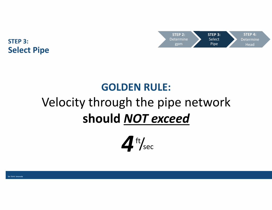
GOLDEN RULE:
Velocity through the pipe network
should NOT exceed
ft/sec4
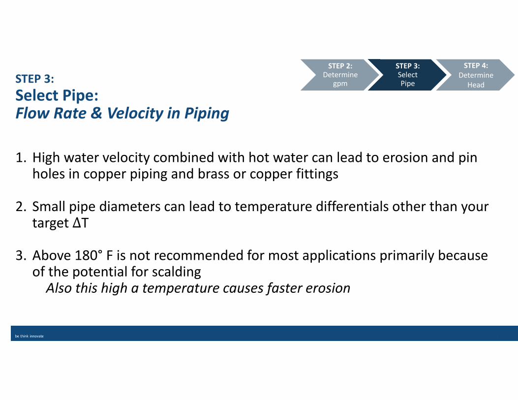
STEP 3:
Select Pipe: Flow Rate & Velocity in Piping
1. High water velocity combined with hot water can lead to erosion and pin holes in copper piping and brass or copper fittings
2. Small pipe diameters can lead to temperature differentials other than your target ΔT
3. Above 180° F is not recommended for most applications primarily because of the potential for scalding
Also this high a temperature causes faster erosion
STEP 3: Select Pipe
STEP 4:
Determine
Head
STEP 2: Determine
gpm
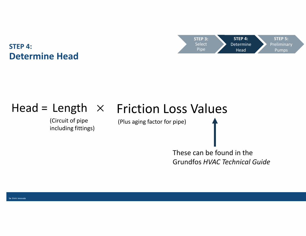
Friction Loss Values
STEP 4:
Determine Head
STEP 4:
Determine
Head
STEP 5:
Preliminary
Pumps
STEP 3: Select Pipe
These can be found in the
Grundfos HVAC Technical Guide
(Circuit of pipe
including fittings) (Plus aging factor for pipe)
Length �Head =
STEP 4:
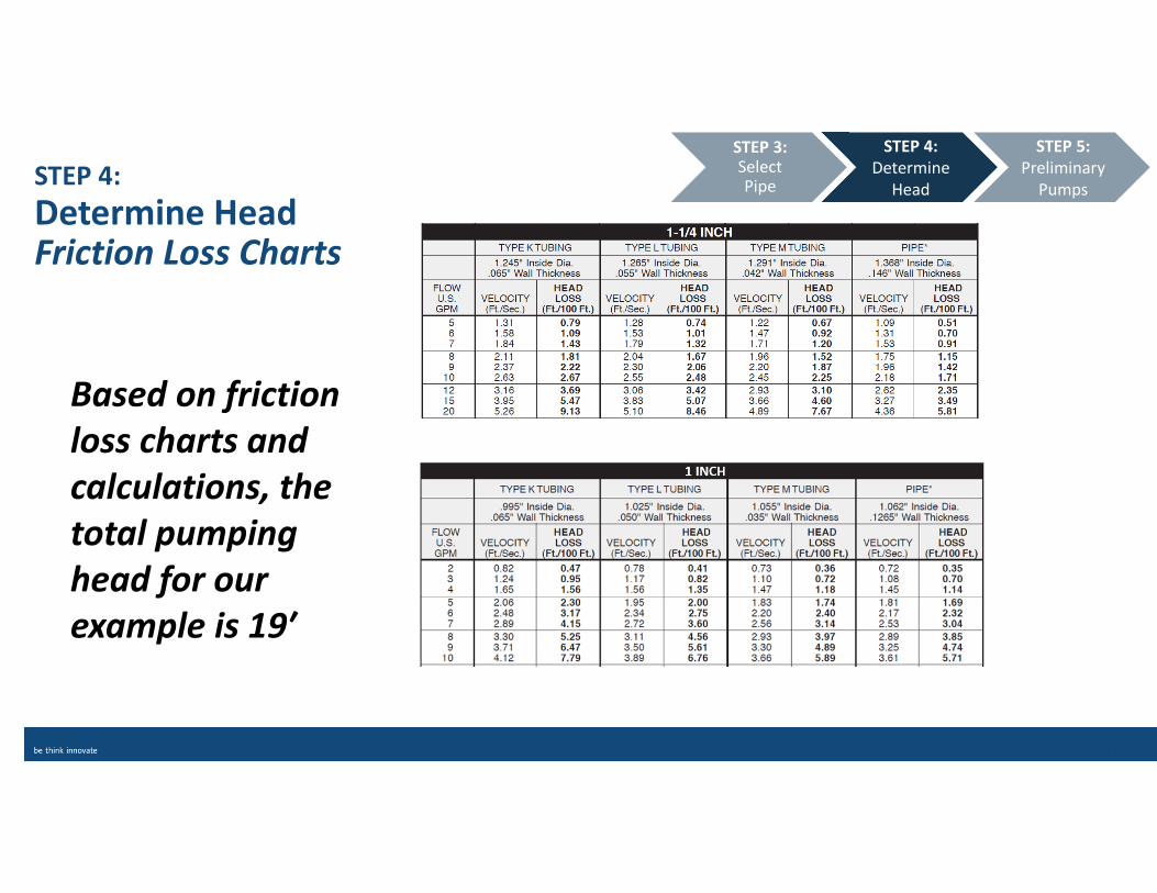
Determine Head Friction Loss Charts
STEP 4:
Determine
Head
STEP 5:
Preliminary
Pumps
STEP 3: Select Pipe
Based on friction
loss charts and
calculations, the
total pumping
head for our
example is 19′
STEP 5:
Preliminary Pump Selection
• Must meet system flow requirement of 5 gpm
• At head of 19′
STEP 5:
Preliminary
Pumps
STEP 6:
Apply System
Curve
STEP 4:
Determine
Head
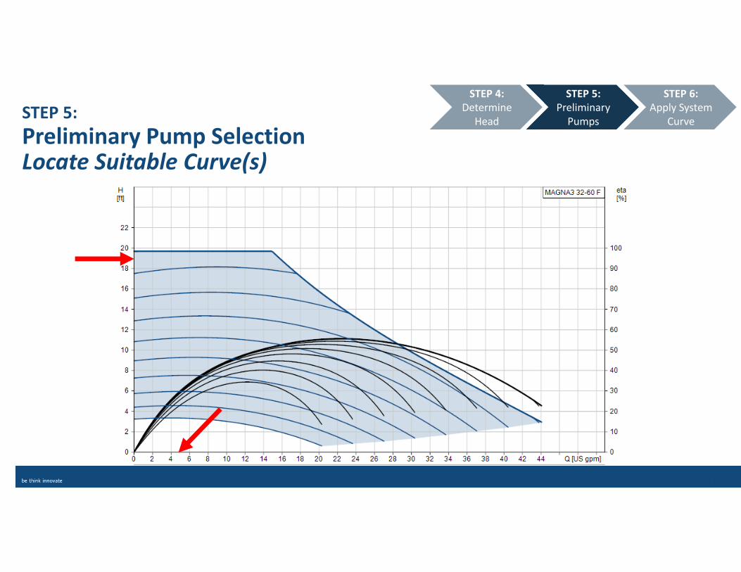
STEP 5:
Preliminary Pump SelectionLocate Suitable Curve(s)
STEP 5:
Preliminary
Pumps
STEP 6:
Apply System
Curve
STEP 4:
Determine
Head
STEP 6:
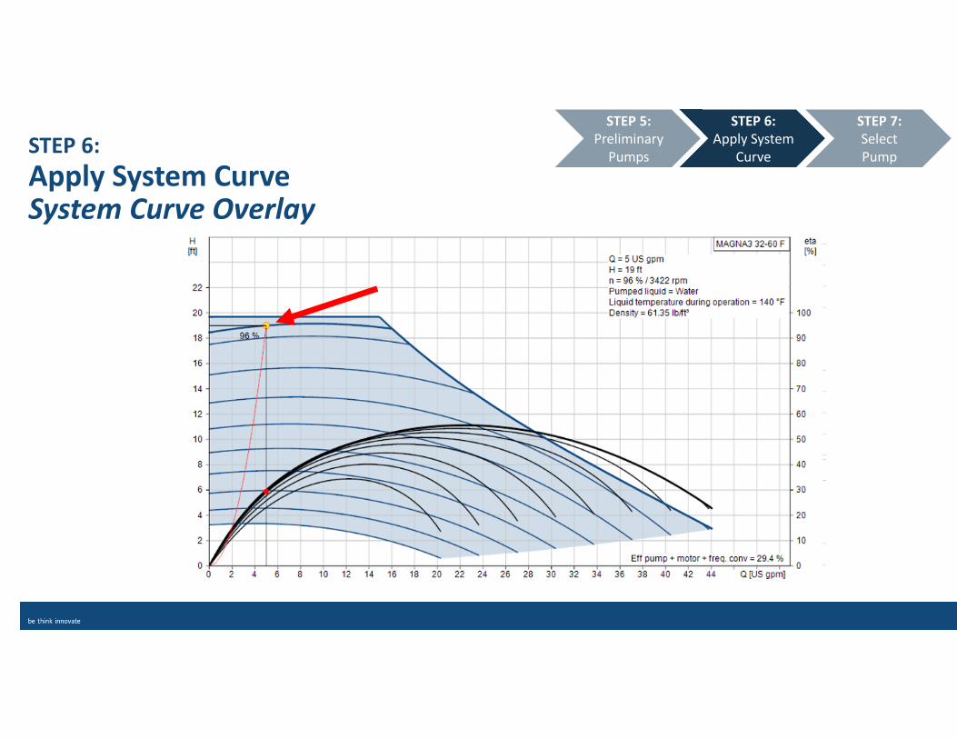
Apply System Curve
• Plot the system’s feet and head point.
• Follow the system curve through the design point to narrow
pump selection
STEP 6:
Apply System
Curve
STEP 7:
Select
Pump
STEP 5:
Preliminary
Pumps
STEP 6:
Apply System CurveSystem Curve Overlay
STEP 6:
Apply System
Curve
STEP 7:
Select
Pump
STEP 5:
Preliminary
Pumps
STEP 7:
Select a Pump
STEP 1:Calculate
BTUh
STEP 2: Determine
gpm
STEP 3: Select Pipe
STEP 4: Determine
Head
STEP 5: Preliminary
Pumps
STEP 6: Apply System
Curve
STEP 7:Select Pump

STEP 7:
Select a PumpPower Consumption
• Compare power consumption on the pump curves
• If comparing efficiency — compare wire-to-water!
• Consider a pump with an ECM (Electronically Commutated
Motor) for superior efficiency
STEP 7:
Select
Pump
STEP 6:
Apply System
Curve
STEP 7:
Select
Pump
STEP 6:
Apply System
Curve
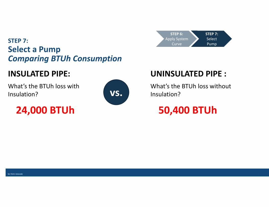
What’s the BTUh loss without
Insulation?
50,400 BTUh
What’s the BTUh loss with
Insulation?
24,000 BTUh
INSULATED PIPE: UNINSULATED PIPE :
vs.
STEP 7:
Select a PumpComparing BTUh Consumption
STEP 7:
Select
Pump
STEP 6:
Apply System
Curve
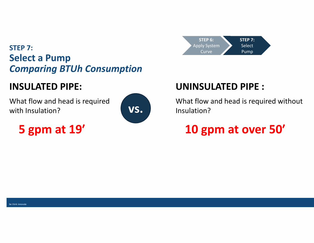
What flow and head is required without
Insulation?
10 gpm at over 50′
What flow and head is required
with Insulation?
5 gpm at 19′
INSULATED PIPE: UNINSULATED PIPE :
vs.
STEP 7:
Select a PumpComparing BTUh Consumption
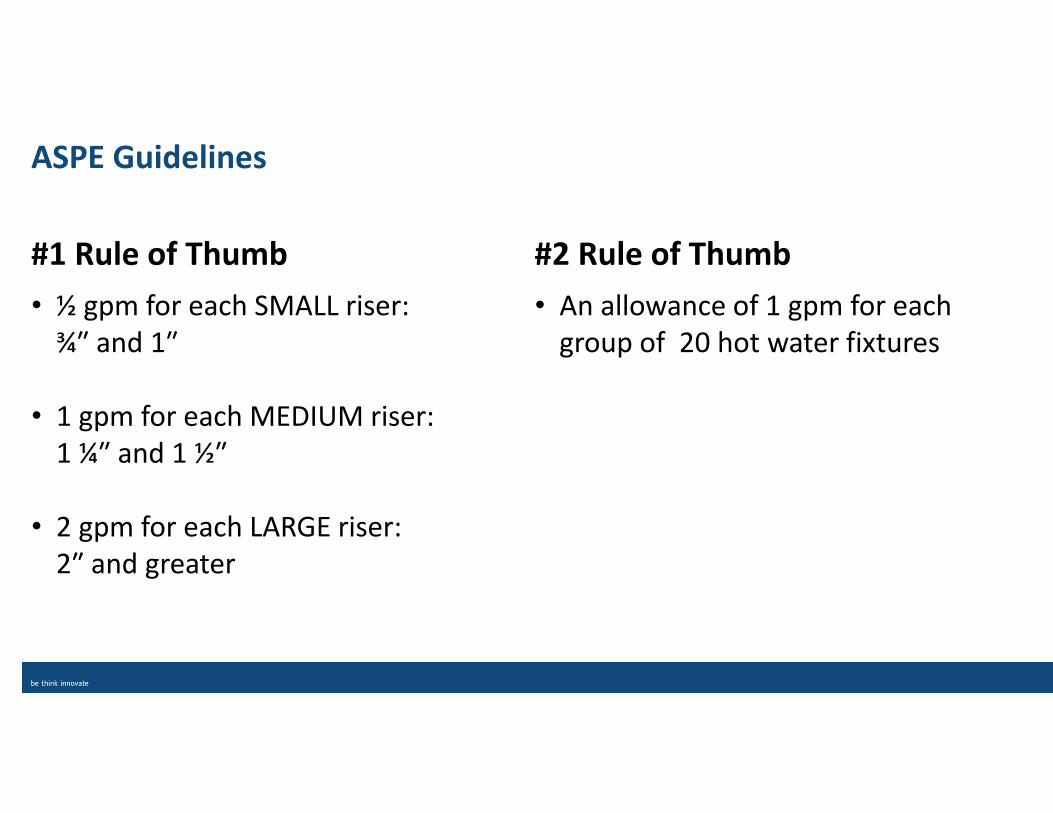
ASPE Guidelines
• An allowance of 1 gpm for each
group of 20 hot water fixtures
• ½ gpm for each SMALL riser:
¾″ and 1″
• 1 gpm for each MEDIUM riser:
1 ¼″ and 1 ½″
• 2 gpm for each LARGE riser:
2″ and greater
#1 Rule of Thumb #2 Rule of Thumb
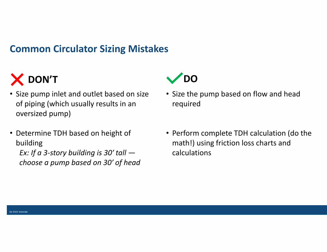
Common Circulator Sizing Mistakes
• Size the pump based on flow and head
required
• Perform complete TDH calculation (do the
math!) using friction loss charts and
calculations
• Size pump inlet and outlet based on size
of piping (which usually results in an
oversized pump)
• Determine TDH based on height of
building
Ex: If a 3-story building is 30′ tall —
choose a pump based on 30′ of head
DON’T DO
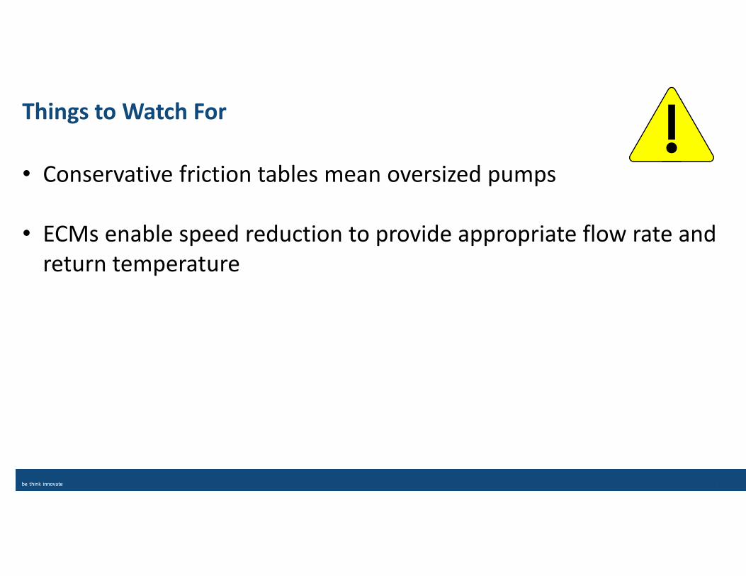
Things to Watch For
• Conservative friction tables mean oversized pumps
• ECMs enable speed reduction to provide appropriate flow rate and
return temperature
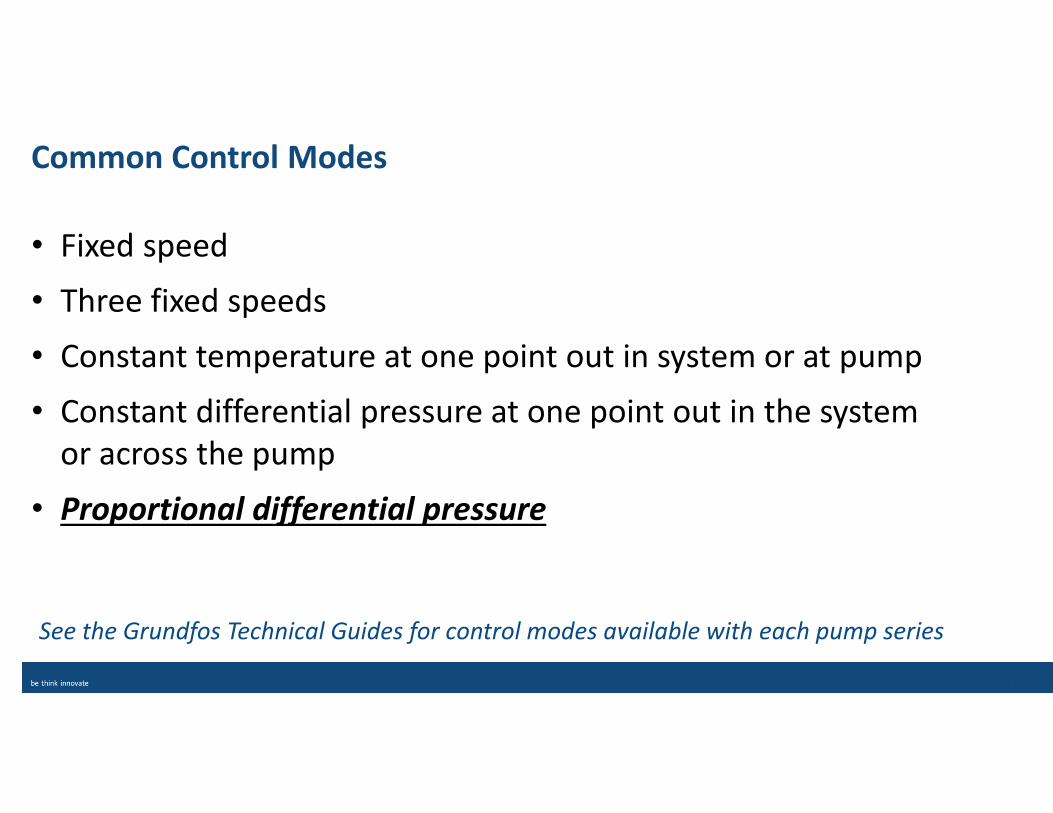
Common Control Modes
• Fixed speed
• Three fixed speeds
• Constant temperature at one point out in system or at pump
• Constant differential pressure at one point out in the system
or across the pump
• Proportional differential pressure
See the Grundfos Technical Guides for control modes available with each pump series

Choosing the Right HWR Pump
1. Flow Rate
2. Head
3. Power Consumption
4. Control Mode
5. Footprint
• UP(S) Wet Rotor Circulators
• MAGNA1 (with ECM)
• MAGNA3 (with ECM)
• CR Multistage
Popular Models Primary Selection Criteria for Pumps:
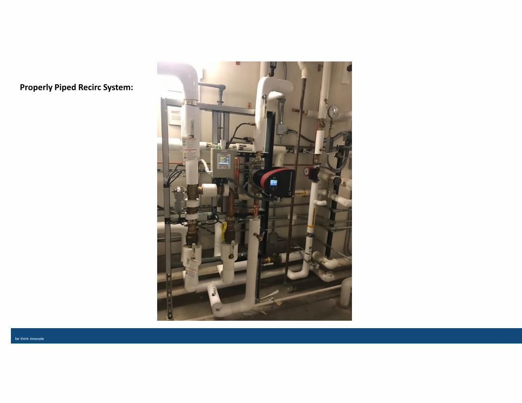
Properly Piped Recirc System:
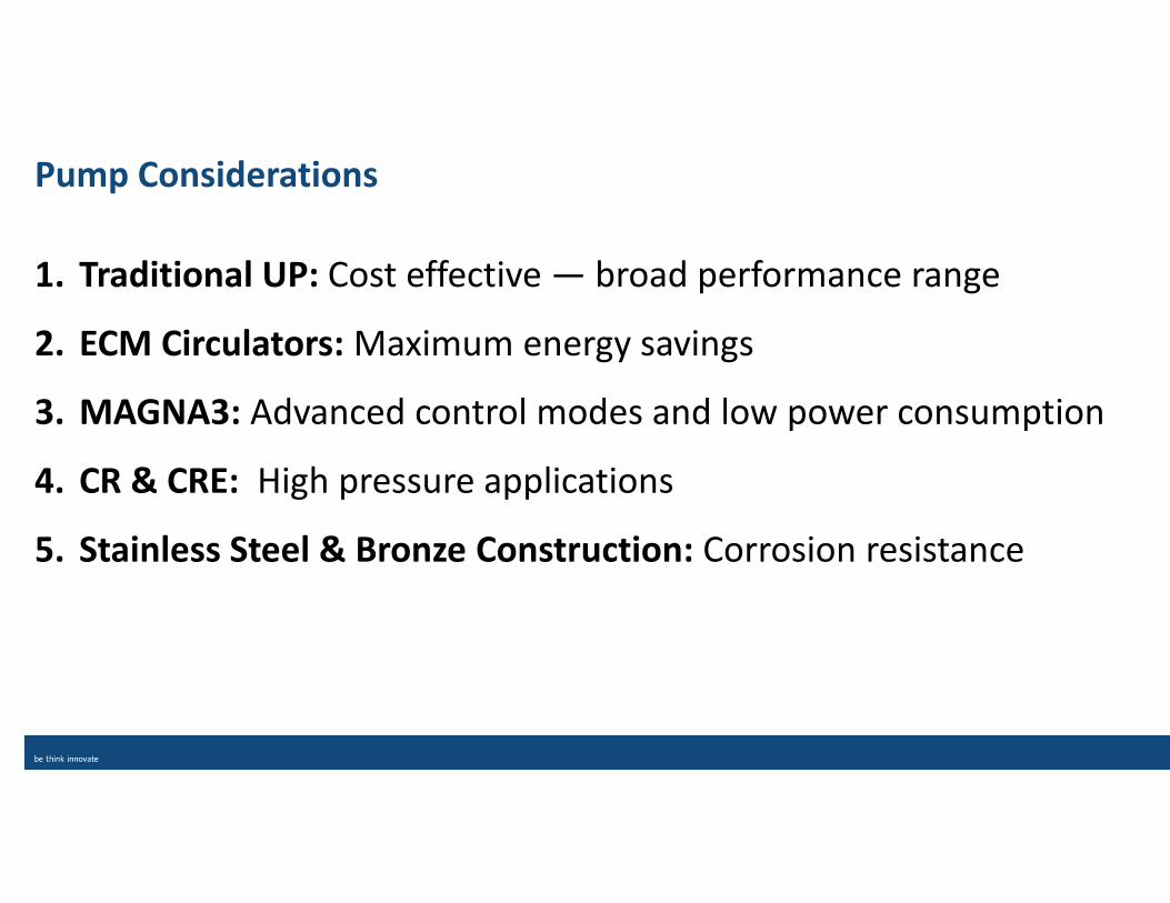
Pump Considerations
1. Traditional UP: Cost effective — broad performance range
2. ECM Circulators: Maximum energy savings
3. MAGNA3: Advanced control modes and low power consumption
4. CR & CRE: High pressure applications
5. Stainless Steel & Bronze Construction: Corrosion resistance
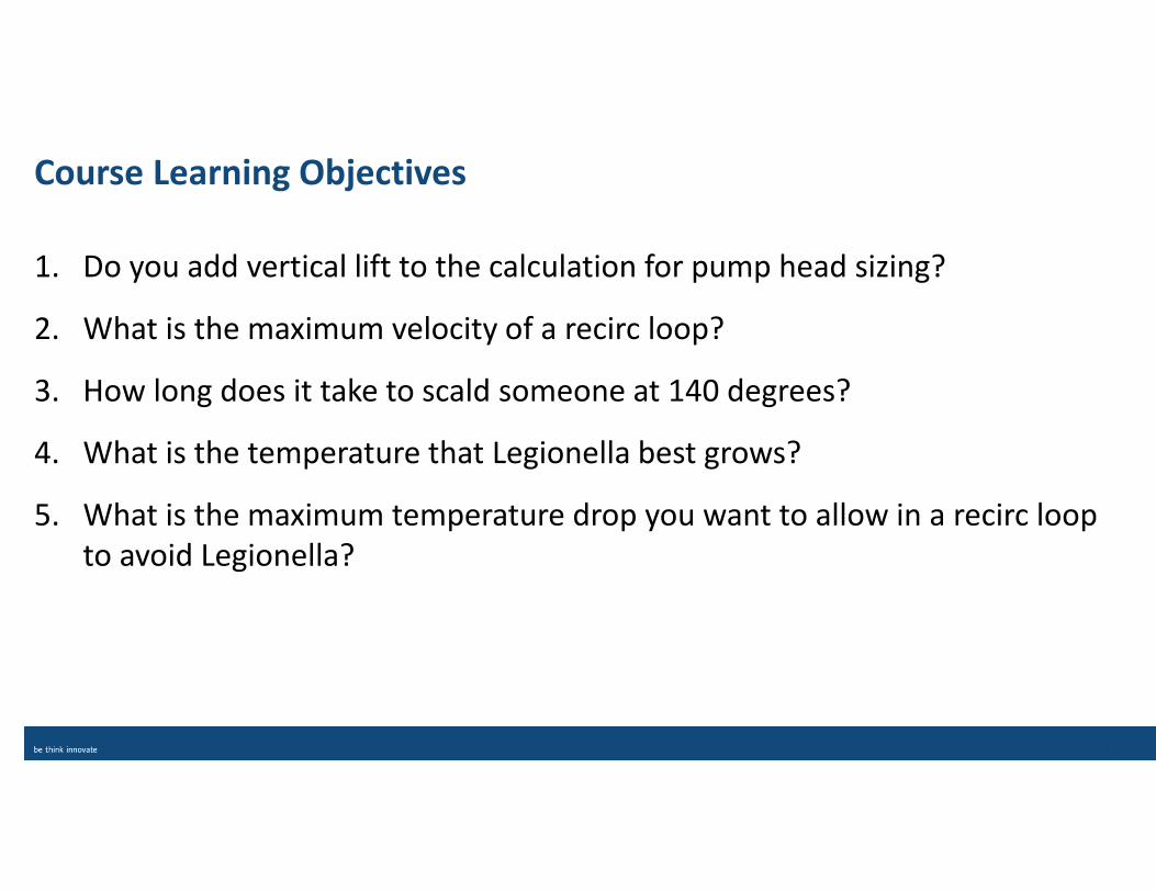
Course Learning Objectives
1. Do you add vertical lift to the calculation for pump head sizing?
2. What is the maximum velocity of a recirc loop?
3. How long does it take to scald someone at 140 degrees?
4. What is the temperature that Legionella best grows?
5. What is the maximum temperature drop you want to allow in a recirc loop
to avoid Legionella?

Answers:
1. No!
2. 4 ft/sec
3. 3 seconds
4. 77-108 degrees
5. 10 degrees - Starting at 120 degrees Fahrenheit

Thank You
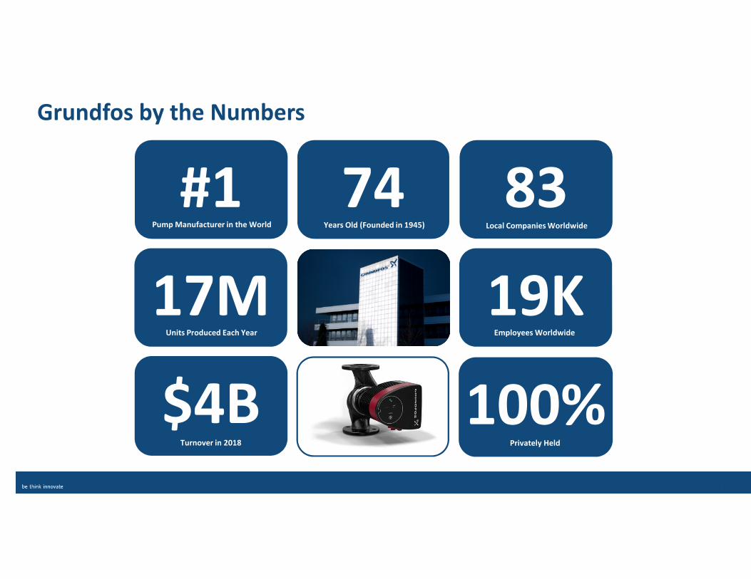
74
19K
83Years Old (Founded in 1945) Local Companies Worldwide
100%
#1
17M
$4B
Pump Manufacturer in the World
Units Produced Each Year
Turnover in 2018 Privately Held
Employees Worldwide
Grundfos by the Numbers

Appendix
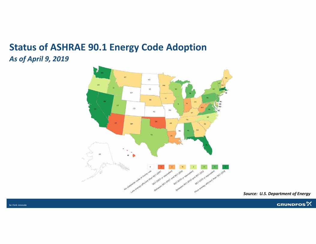
Status of ASHRAE 90.1 Energy Code Adoption As of April 9, 2019
Source: U.S. Department of Energy
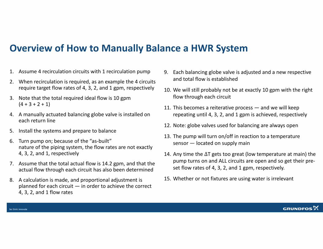
9. Each balancing globe valve is adjusted and a new respective
and total flow is established
10. We will still probably not be at exactly 10 gpm with the right
flow through each circuit
11. This becomes a reiterative process — and we will keep
repeating until 4, 3, 2, and 1 gpm is achieved, respectively
12. Note: globe valves used for balancing are always open
13. The pump will turn on/off in reaction to a temperature
sensor — located on supply main
14. Any time the ΔT gets too great (low temperature at main) the
pump turns on and ALL circuits are open and so get their pre-
set flow rates of 4, 3, 2, and 1 gpm, respectively.
15. Whether or not fixtures are using water is irrelevant
1. Assume 4 recirculation circuits with 1 recirculation pump
2. When recirculation is required, as an example the 4 circuits require target flow rates of 4, 3, 2, and 1 gpm, respectively
3. Note that the total required ideal flow is 10 gpm (4 + 3 + 2 + 1)
4. A manually actuated balancing globe valve is installed on each return line
5. Install the systems and prepare to balance
6. Turn pump on; because of the “as-built” nature of the piping system, the flow rates are not exactly 4, 3, 2, and 1, respectively
7. Assume that the total actual flow is 14.2 gpm, and that the actual flow through each circuit has also been determined
8. A calculation is made, and proportional adjustment is planned for each circuit — in order to achieve the correct 4, 3, 2, and 1 flow rates
Overview of How to Manually Balance a HWR System