Embed Size (px)
Citation preview

February 2021
1
COYOTE® STP-L
Be sure to read and completely understand this procedure before applying product. Be sure to
select the proper PREFORMED product before application.
NOMENCLATURE
1. Base (1)
2. Cover (1)
3. Base tray (1)
4. Splice tray (2-4)
5. Cover lanyard (1) [Aerial applications only]
6. Grommet (6)
7. Silicon sachet (3)
8. Fiber pick (1)
9. Self-tapping screws (9-14)
10. Plug (6-24)
11. Tray hinge (1) [Cross-connect, 72 & 96 Fiber only]
12. Bulkhead (1) [Cross-connect only]
13. Pole mount bracket (1) [Aerial applications only; complete with pole mounting hardware]
14. Tray dust cover (1)
15. Transportation tube
16. Cable retention hardware
17. External cable fixation bracket (1) [Aerial applications only; complete with hose clamps]
1
2
3
4
6
7
8 9
11
12
13
5
10
14
15
16
17
February 2021
2
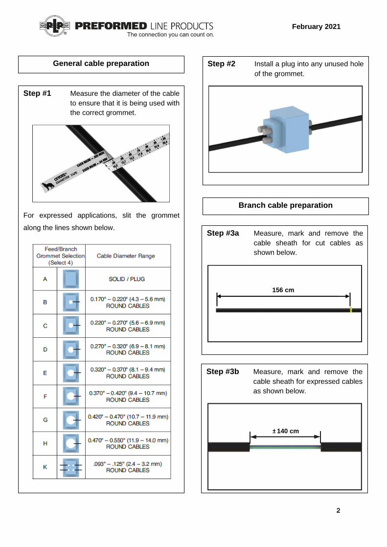
Step #1 Measure the diameter of the cable
to ensure that it is being used with
the correct grommet.
For expressed applications, slit the grommet
along the lines shown below.
Step #2 Install a plug into any unused hole
of the grommet.
General cable preparation
Step #3a Measure, mark and remove the
cable sheath for cut cables as
shown below.
Branch cable preparation
156 cm
Step #3b Measure, mark and remove the
cable sheath for expressed cables
as shown below.
140 cm

February 2021
3
Step #5 Remove the buffer tubes for cut
cables at a minimum of 6mm and
a maximum of 1000mm away
from sheath opening.
1000 mm
Step #6 Adjust the cable so that the
sheath opening is positioned
19mm away from the grommet.
Step #4 With the sheath removed,
measure and cut 100mm of yarn
and 30mm of strength member for
tie-off.
30
Step #7 Lubricate all four outer surfaces
each grommet. Once the lubricant
has been applied, smear it to
provide a thick coating on each
surface. Lubricate all mating
surfaces of the closure including
around the cable and the cover
gasket.
Step #8 Insert the grommets into the outer
pockets of the base. Ensure the
grommets are fully installed.

February 2021
4
Step #10b Route the buffer tubes (alternate
orientation). Cable ties can be
used to secure buffer tubes to
hooks.
Step #9 Insert retention clips into the slots
on the base. Ensure they are fully
installed. See STP Retention
clips applications instructions
for cable retention instructions.
Drop cable preparation
Step #10a Route the buffer tubes.
Step #11 Measure, mark and remove the
cable sheath as shown below.
Buffer tube routing
106 cm Aramid yarn retention screw &
strength member retention slot

February 2021
5
Step #12 With the sheath removed,
measure and cut 100mm of yarn
and 30mm of strength member for
tie-off.
30
Step #13 Remove the buffer tubes for cut
cables 6mm away from sheath
opening.
6mm
Step #14 Adjust the cable so that the
sheath opening is positioned
19mm away from the grommet.
Step #15 Align the grommets with the base
tray. Insert retention clips into the
slots on the base tray. Ensure
they are fully installed. See STP
Retention clips applications
instructions for cable retention
instructions.
Step #16 Route the incoming fibers.
Fiber routing in the base tray
To splice tray
retention screw &
strength member
retention slot
Aramid yarn retention screw
Additional cable tie-off points
Strength member retention
slots
Additional cable tie-off points
PLC Splitter block retention
slots
PLC Splitter tail splice
retention slots
Outer ring can be used for
additional buffer tube storage
February 2021
6
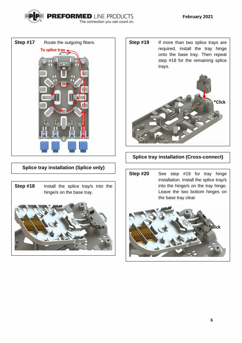
Step #17 Route the outgoing fibers.
To splice tray
retention screw &
strength member
retention slot
Splice tray installation (Splice only)
Step #18 Install the splice tray/s into the
hinge/s on the base tray.
*Click
Step #19 If more than two splice trays are
required, install the tray hinge
onto the base tray. Then repeat
step #18 for the remaining splice
trays.
*Click
Splice tray installation (Cross-connect)
Step #20 See step #19 for tray hinge
installation. Install the splice tray/s
into the hinge/s on the tray hinge.
Leave the two bottom hinges on
the base tray clear
*Click

February 2021
7
Step #21 Ensure that all bare fiber being
routed to the splice tray/s are
routed through the transportation
tube provided. Cut the
transportation tube to length as
required.
Fiber routing in the splice tray (Splice only)
Step #22 Secure the transportation tube to
the tie-off points on the splice tray
using the cable ties provided.
Cable tie-off points
Step #23 Route the incoming fibers
OR
From base tray
retention screw &
strength member
retention slot
From base tray
retention screw &
strength member
retention slot

February 2021
8
Step #24 Route the outgoing fibers
OR
From base tray
retention screw &
strength member
retention slot
From base tray
retention screw &
strength member
retention slot
Step #25 Splice the incoming fibers to the
outgoing fibers per your accepted
company practice (Skip to step
36).
Fiber routing in the splice tray (Cross-connect)
Step #26 Follow steps 21 & 22. Route the
incoming fibers.
OR
From base tray
retention screw &
strength member
retention slot
From base tray
retention screw &
strength member
retention slot

February 2021
9
Step #27 Route the outgoing fibers
OR
Note: A fiber pick is provided on the
inside of the cover to assist in
maneuvering fibers when routing.
Preparation and routing of pigtails (Cross-connect)
Step #28 Measure and mark the jacket of the pigtails as shown below. Remove the jacket of each pigtail beyond the marked location.
Step #29 Splice the incoming fibers to the
incoming pigtails and the outgoing fibers to the outgoing pigtails per your accepted company practice.
From base tray
retention screw &
strength member
retention slot
From base tray
retention screw &
strength member
retention slot

February 2021
10
Step #30 Follow steps 21 & 22. Route the
incoming pigtails.
OR
To base tray
retention screw &
strength member
retention slot
Step #31 Route the incoming pigtails
(continued)
OR
From splice tray
retention screw &
strength member
retention slot
To base tray
retention screw &
strength member
retention slot
From splice tray
retention screw &
strength member
retention slot

February 2021
11
Step #32 Route the outgoing pigtails.
OR
To base tray
retention screw &
strength member
retention slot
Step #33 Route the outgoing pigtails
(continued)
OR
From splice tray
retention screw &
strength member
retention slot
From splice tray
retention screw &
strength member
retention slot
To base tray
retention screw &
strength member
retention slot

February 2021
12
Bulkhead installation (Cross-connect only)
Step #36 Secure the bulkhead bracket to
the base tray by tightening the
screws provided.
Bulkhead bracket
Screws
Step #37 Install the adapters into the
bulkhead. Insert the pigtail
connectors into the adapters as
required.
Adapter
Splice tray dust cover installation
Step #34 Install the splice tray dust cover
on the uppermost tray as shown
below.
*Click
Splice tray indexing
Step #35 When raising splice trays, insert
the tab on each successive tray
into the hole on the tray above.

February 2021
13
Step #40 Place the cover on the base. Secure the cover by pressing down on it and rotating the latches until they snap in place over the cover. Tighten the screw sufficiently with the allen key provided. Max torque – 4Nm
Screw
External fixation bracket installation
(Aerial applications only)
Step #41 Secure the external cable fixation bracket to the STP-L by tightening the screw provided.
Screw
Cover installation
Step #38 Lubricate the grommets as per
step #7. Secure the base tray to
the base by tightening the screws
provided.
Base tray
Base
Screws
Step #39 Lubricate the cover gasket with a light coating of silicone lubricant.
Gasket
Base tray installation
Fiber pick
storage location

February 2021
14
Mounting bracket installation (Strapped)
Step #44 Secure the mounting bracket to the pole using the strapping provided. Ensure the keyhole slots are oriented as shown below.
Mounting bracket installation (Coach
screws)
Step #45 Secure the mounting bracket to the pole using the coach screws provided. Ensure the keyhole slots are oriented as shown below.
Step #42 Secure the cable to the external fixation bracket using the hose clamp provided.
STP-L Preparation for mounting bracket
(Aerial applications only)
Hose clamp
Step #43 Install mounting screws as shown below.
Screws
±3mm

February 2021
15
180 Ohrtmann Road Willowton | P.O. Box 4015 | Willowton | Pietermaritzburg 3200 +27(0)33 3975800 www.preformedsa.co.za
SAFETY CONSIDERATIONS This application procedure is not intended to supersede any company construction or safety standards. This procedure is offered only to illustrate safe application for the individual. FAILURE TO FOLLOW THESE PROCEDURES MAY RESULT IN PERSONAL INJURY OR DEATH. Do not modify this product under any circumstances. This product is intended for use by trained technicians only. This product should not be used by anyone who is not familiar with, and not trained to use it. When working in the area of energized lines, extra care should be taken to prevent accidental electrical contact. For proper performance and personal safety, be sure to select the proper size PREFORMEDTM product before application. PREFORMED products are precision devices. To insure proper performance, they should be stored in cartons under cover and handled carefully.
© 2021 Preformed Line Products Company. All rights reserved.
Step #46 Install the STP-L onto the mounting bracket.
Cover lanyard installation
(Aerial applications only)
Step #47 Remove the M6 bolt from the cover and install the cover lanyard with the screw as shown below. Ensure the O-ring is put back in place after installation.
Screw
O-ring