Embed Size (px)
Citation preview

JH-Li,.~Vl . ) TR J;'01C) C
0,¢
ROYAL AEROSPACE ESTABLISHMENT
Technical Report 88012
February 1988
CRAG TE-ST METHODS FOR THEMEASUREMENTOF THE ENGINEERINGPROPERTIES OF FIBRE REINFORCED
PLASTICS
edited by 15T D
P. T Curti., NOV 0 , UaL' " lJ ]h lf * 'h N I f , .,
Pro#nurement Executive, Ministry of DofoncoFarnboroutgh, Hants
UNLIMITED

[ ~ONLL4ZTED
R O Y A L A E R O S P A C E E S T A B L I S H M E N T
Technical Report 88012
Received for printing 16 February 1988
CRAG TEST METHODS FOR TEE EASURE NT OF TEE ENGWTERING
ROPEIS OF FIBRE RzINORCED PLASTICS
edited by
P. T. Curtis
SUMMIARY
This Report is the third and final issue of a document describing test
methods suitable for the measurement of the engineering properties and other
associated properties of fibre reinforced plastics. Specimen configurations and
testing procedures are detailed and the applicability of the tests to the
different types of fibre reinforced plastics is discussed.
Departmental Reference: Materials a Structures 218
Copyvright
ControZler HMSO London1988
UNLIMITED

2 UNLDaTED
LIST Or COiITENTS
Page
Background and membership of the CRAG Working Group on test methods 4
Part 0 - Introduction 5
Part 1 - Shear test methods
Method 100 - Method of test for interlaminar shear strengthof fibre reinforced plastics 10
Method 101 - Method of test for in-plane shear strength andmodulus of fibre reinforced plastics 12
Method 102 - Method of test for lap shear strength of fibrereinforced plastics 15
Part 2 - Flezural test methods
Method 200 - Method of test for flezural strength andmodulus of fibre reinforced plastics 19
Part 3 - Tensile test methods
Method 300 - Hethod of test for the longitudinal tensile strengthand modulus of unidirectional fibre reinforcedplastics 21
Method 301 - Method of test for the transverse tensile strengthand modulus of unidirectional fibre reinforcedplastics 24
Method 302 - Method of test for the tensile strength andmodulus of multidirectional fibre reinforcedplastics 27
Method 303 - Method of test for the notched tensile strengthof multidirectional fibre reinforced plastics 30
Part 4 - Compression test methods
Method 400 - Method of test for longitudinal compressionstrength and modulus of unidirectional fibrereinforced plastics 33
Method 401 - Method of test for longitudinal compressionstrength and modulus of mltidirectionalfibre reinforced plastics 36
Method 402 - Method of test for notched compression strengthof multidirectional fibre reinforced plastics 43
Method 403 - Method of test for residual compression strengthafter impact of multidirectional fibre reinforcedplastics 47 7
UNLMTED
I-

UNILflTED
Part 5 - Methods of test for fatigue properties
Method 500 - Methods for the preparation of test specimensfor the measurement of fatigue properties offibre reinforced plastics 52
Part 6 Methods of test for tougaess
Method 600 - Metod of test for tuterlghnemr fracture toughnessof fibre reinforced plastics 54
Part 7 - Methods of test for bearing properties
Method 700 - Method of test for bearing properties of multi-
directional fibre reinforced plastics 57
Part 8 - Physical test methods
Method 800 - Method of test for the density of fibre reinforcedplastics 61
Method 801 - Method of test for the determination of thecoefficient of linear thermal expansion of fibrereinforced .plastics 63
Method 802 - Method of test for the outgassing of fibre
reinforced plastics 67
Part 9 - Environmental effects
Method 900 - Background information on environmental effects 78
Method 901 - Method of assessment of diffusivity propertiesof fibre reinforced plastics 88
Method 902 - Method of conditioning of fibre reinforcedplastics under hot/vat environments 96
7 Part 10- miscellaneous tests
Method 1000 - Methods of assessment of fibre volume fractionof fibre reinforced plastics 100
Method 1001 - Method of assessment of void volume fraction offibre reinforced plastics by ultrasonic scanning 104
Report documentation page inside back cover
UNLIMITED

4 UNLIMITED
BACKGROUND AND MEMBERSHIP OF THE CRAG WORKING GROUP ON TEST METHODS
The Working Group was inaugurated in 1980 by the Composite Research Advisory
Group (CRAG) with terms of reference including a requirement to survey and rarion-alise current test procedures for fibrous composite materials. This group has
now agreed test methods for the generation of materials design data, primarily
on undirectional composite materials for use in design aids such as laminated
plate theory, but also on multidirectional fibre composites where this is notobrtAnable by other means. This Report is the third and final formal issue of
test methods by the group, which has nov ieen dissolved. The methods detailed
under sections 301 and 800 - 1001 are new additions in this document. Other
methods have been revised where appropriate to cover developments since their
previous issue as RAE reports TR .84102 and Ti 85099.
The test methods which follow are a result of collaboration between the
Royal Aircraft Establishment, Farnborough, British Aerospace plc (Warton,
Woodford and Stevenage Divisions), Westland Helicopters Limited, Short Brothers,
Rolls Royce and Ciba Geigy (UK) Limited.
Current membership of the group:-
Mr N.L. Bottrall - WRL Yeovil (Chairman)Mr D. Bradwell - BAe StevenaseMr P.E. Brooks - Ciba Geigy (UK) Ltd (Secretary)Mr H. Calder - BAa WoodfordDr P.T. Curtis - RAE Farnborough (S4)Mr E.C. Edge - BAa WartonMr A.B. Hamill - Short Bros, BelfastDr J. Hill - Rolls Royce, Derby
o.cesslon For
DTIC TABUnannounced 0Justification
Distribution/
AvailabilitY CodesiAva11 and/or
Dist Special
UNLIMITED -'

unnalITED
0 INTRMUCTION
The test methods recommended in these data sheets apply to resin matrix
composites reinforced with orientated continuous fibres. They are valid for all
grades of carbon glass and aramid fibres, in both U/D tape and woven fabric forms
including mixed fibre hybrid combinations, provided that the modes of failure are
representative. Epoxy resin matrix systems were used in the development of these
methods, but, although confirmatory test evidence is lacking, other resin systems
should be equally suitable provided that the composite properties fall within any
prescribed test limitations and that valid failure modes are obtained.
All multidirectional laminates, including woven fabric laminates, must
have their ply orientations and stacking sequence balanced about the mid-plane
and the longitudinal axis to ensure axial loading and to prevent rotational,
flexural, or off-axis displacements. (ge/.4' P '' t, " "
All laminates should be assessed for quality using an ultrasonic scanning
technique, as described in section 1001.
Machining
The machining of fibre reinforced plastics must be carried out with care
to minimise damage, eg delamination, splitting, etc. CFRP and GRP can be machined
with relative ease but KRP is more difficult and reference should be made to
'Machining of Kevlar Composites' which is obtainable from Du Pont deNemours
International SA, Industrial New Products Section, Textile Fibres, PO Box CE-1211,
Geneva 24.
CFRP and GRP may be readily sawn or drilled but require the use of diamond
impregnated or tungsten carbide tools because of the rapid dulling of cutting
surfaces. All tools must be kept clean and free from grit. High pressure water
jets have also proved successful in the cutting of these materials.
The drilling of holes requires particular care to ensure that delamination
does not occur on the exit face when the drill breaks through. The composite
should be adequately backed by a suitable piece of sacrificial material and feed
rates should be slow but uniform.
Saw marks on the edges of test specimens may be detrimental to the results
obtained and should be removed. Any such marks on the longitudinal edges may be
removed by grinding or abrading with suitable (320 grade approximately) vet/dry
emery paper.
UNLIMITED

6 UNLMITED
Provided the moulded thickness is correct, laminated surface finishes are
generally acceptable. It should be noted that many peel plies used in the
manufacture of composite materials can give rise to a resin rich dimpled surface
which may result in the overestimation of panel thickness. This effect may be
particularly significant for thin specimens and flexure tests, when removal of
the dimples may be advisable. If a specimen has to be reduced in thickness
(unidirectional laminates only) surface grinding may be used.
Grinding operations for CM and GRP should be undertaken using a diamond
coated or open grit carbide grinding wheel. Cutting speeds should be adjusted
to avoid over-beating of the specimen. Certain proprietary liquid coolants may
be used to prevent free dust and minimise wheel clogging. It is essential to
ensure that any coolant used does not affect the matrix properties and can be
cleaned off prior to attaching end tabs.
When any form of dry machining is undertaken it is essential that an
efficient dust extraction system is employed.
Furthermore, personnel involved should wear the appropriate safety equip-
ment, eg filter masks.
Adhesive bondini
Thorough surface preparation is essential prior to bonding on end fittings.
Test pieces and end tags should be abraded and degreased to remove any surface
contaminants in the area to be bonded. Dimpled surfaces produced by a peel ply
during manufacture may only require degreasing. Aluminium alloy parts should be
etched and cleaned in accordance with Method 0 of BSI Code of Practice CP3012
(Method 0 of DEF Standard 03-2/1).
The adhesive employed mast be capable of withstanding the particular test
environment, but attention must be paid to the residual thermal stresses arising
from any hot bonding, in particular the peeling forces at the ends of the lami-
nates. Cold cure epoxy adhesives are recommended for normal applications. Hot
cure epoxy films and GRP end tags (to reduce the residual stresses) are necessary
for severe test environments.
Test machines and instrumentation
The test machine should conform to the calibration standard BS 1610: 1985
Grade 1.0 and be equipped to record applied load and cross-head deflection rate.
C
UNLIMITED

UNLIMITED
Accurate load alignment and cross head movement are essential for satis-
factory testing. Uf necessary a suitable test rig should be employed to ensure
the required accuracy.
Continuous or 'ramp' loading is preferred with continuous load and strain
recording. If incremented loading is used it should be noted in the test report.
Strain gauges are recomended rather than extensometers for strain record-
ing, as their results have been found to be more reliable. It is recommended
that strain gauges are attached to both faces of the specimens to enable any
out-of-plane bending effects to be measured. Careful surface preparation is
necessary before bonding on the Saups. The gauges should be given a suitable
protective covering if the specimen is to be subjected to environmental
conditioning.
Strain gauges can sometimes fail during prolonged fatigue testing, and it
is therefore prudent to undertake a secondary check at intervals, possibly by
monitoring machine ram displacements.
Report
The report for any test performed should include:'
i) A description of the test method and type of specimen used,
together with its critical dimensions, type of end fittings and adhesives
employed.
(ii) Fibre and resin type, weave style, preimpregnate batch identifi-
cation, number of plies and their orientation and stacking sequence,
laminate processing details.
(iii) The fibre volume fraction of the laminate as described in
section 1000.
(iv) The environmental history of the specimen prior to test.
(v) The environmental conditions of temperature and humidity versus
time during test.
(vi) Variations in the specimen average moisture levels throughout
manufacture conditioning, and testing as monitored by the traveller.
(vii) The number of specimens tested for each property. (A minimum of
five is recomended for static testing.)
UNLXITED

UNLIXTED
(viii) The failure load, stress and mode of failure (if applicable) for
each specimen, together with the mean failure stress for all the specimens
and the coefficient of variation. (Coefficient of variation is given by:
C 2.00.[(x )2]
where 7 is the arit -etic mean and n is the number of values of x
(ix) Actual and nominal thickness deduced from nominal cured ply
thickness at a specified fibre volume fraction.
(x) Where applicable - the stress - strain curve, secant modulus and
Poisson's ratio for each specimen, together with the mean secant modulus
(and strain range used) and Poisson's ratio for all the specimens and the
coefficient of variation.
SRESS MEASUED T[ST CURVE
0.255STRAIN0.2S%
tan a a SECANT MOCULUS AT 0.2S% STRAIN
Fig 0.1 Typical stress-strain curve
NOTES: (1) A strain range of 0.25Z is recommended, but this may be varied
if necessary to suit a particular application.
(2) Any initial irregularities in the stress/strain curve should
be ignored and the curve should be extrapolated back to determine
the origin.
(3) The shape of the curve may vary with material and test.
(xi) For fatigue tests - mean stress, stress amplitude, number of
stress cycles to failure, frequency of loading, or load spectrum, and if
appropriate the residual strength and/or stiffness.
UNLIuITED
L -

UNLLMITED
(xii) The date of the test.
(xiii) Any observations made during the test that may be relevant to the
results obtained or any deviations from the recomendations, eg incremental
instead of continuous loadig.
Deviations from the standards
In certain cases some dimensional variations can be permitted without
significantly affecting the validity of the test results. Where applicable these
are given in the appropriate Data Sheets. Any deviations outside the permitted
range may invalidate the test results.
Specific comments
i) Mltidirectional tensile specimen (Data Sheets 303 and 402) Notch
sensitivity varies with hole size, particularly for GRP.
(ii) The maximu testing times recommended may be too long to ensure the
absence of creep deformation particularly at elevated temperature and with
high moisture content. In all cases a time to failure at the lower end of
the range is preferred.
UNLIMITED

10 ULflrTED
100 METHOD OF TEST FOR INTERLAMINA SHEAR STRENGTH OF FIBRE RE fFORCEDPLASTICS
t
Fig 100.1
Description
This is a three-point flexure test for reinforced plastic specimens with a
span to depth ratio low enough to produce matrix shear failure.
Materials
The test may be used for any form of material, subject to the 'validity'
requirements below. The test specimen mast be axially orthotropic.
Nomenclature
t a specimen thickness w - specimen width
to nominal specimen thickness L - specimen length
S a span between supports P - load at failure
Dimensions
t - 2.0 me (nominal or nearest w a 5t t 0.25 mma mouldable thickness) n
S - 5t t 0.5 mm (1)L - (t a 10.0 Om) * 0.5 ma S - 4t t 0.5 mm (2)
All dimensions must be parallel to :.0.05 mm
.Support rollers diameter 6 m
Loading roller diameter 6 m (10 mm acceptable).
NOTES: (1) For materials having a flexural strength to shear strength
ratio greater than 10:1.
(2) For materials having a flexural strength to shear strength
ratio less than 10:1. C
UNLIMITED
....A -- mm a m m ".....,.. ...
TNLDMITED
Test requirements
The specimen must be located symetrically on the support rollers. The
loading roller must be constrained to move vertically above the centreline of
the specimen. A jig shall be used to ensure accurate alignment.
Load shall be increased uniformly to cause failure within 15-45 seconds.
Calculation
Interlaminar shear strength is given by:
ILSS - 0.75 P/vt
Accurately measured values of v and t must be used. Adjustment of the
result to a standard volume fraction (Vf) is not permissible. Report ILS
strength, Vf .
It is important to note that the value obtained tor ILSS is highly dependent
upon the span to depth ratio.
Validity
For result to be meaningful, the failure mode must be either single or
multiple shear or plastic deformation with evidence of shear failure.
Fletural failure or plastic deformation without evidence of shear failure
will produce only a lower bound value of ILSS.
~ single shear - VALID
~ multiple shear - VALID
>Plastic deformation - VALIDwith evidence of
shear failure
>Flexural failure - INVALID
Fig 100.2
UNLIMITED

12 UNLIMITED
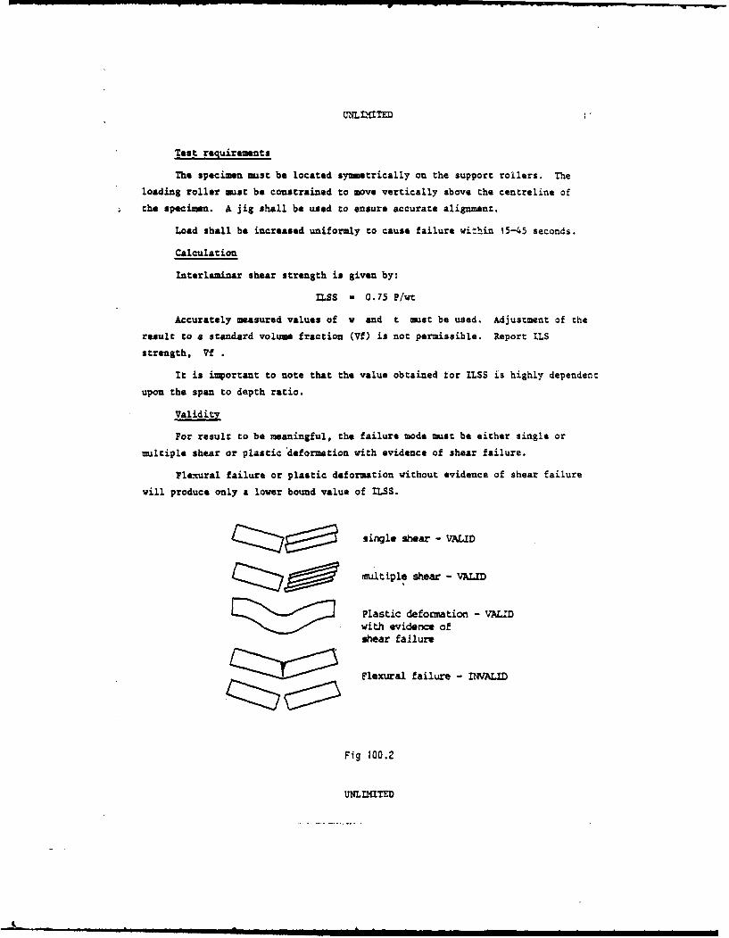
101 METHOD OF TEST FOR IN-PLANE SHEAR STRENGTH AND MODULUS OF FIBRE REINFORCEDPLASTICS
END TAB 0.5-2.0 me THICK
Fig 101.1
Description
This specimen is used to determine the in-plane shear strength and modulus
of reinforced plastic materials. The test is suitable for either unidirectional
tape or woven fabric, and measures the shear properties associated with an
individual layer. The specimen, which is subjected to tensile loading, comprises
a laminate with the fibres inclined at 45 degrees and -45 degrees to the longi-
tudinal axis. To avoid distortions and induced bending the lay-up must be fully
symmetric. In the case of undirectional tape, the layers are alternately at
45 degrees and -45 degrees up to mid-plane, then alternately at -45 degrees and
45 degrees, with an equal number of layers in each direction.
A pair of strain gauges (at 0 degrees and 90 degrees to 0 degree axis) is
required at the centre of the specimen to measure modulus. (It is preferable to
use a pair on each face to average out specimen bending.)
The and tabs are either soft aluminium alloy or GEP attached using a
suitable adhesive.
Testing without end tabs is permissible provided that suitable end grips
are used.
Nomenclature
e - length of end tabs
- measured thickness of specimen
w - measured width of specimen
UNLIMITED
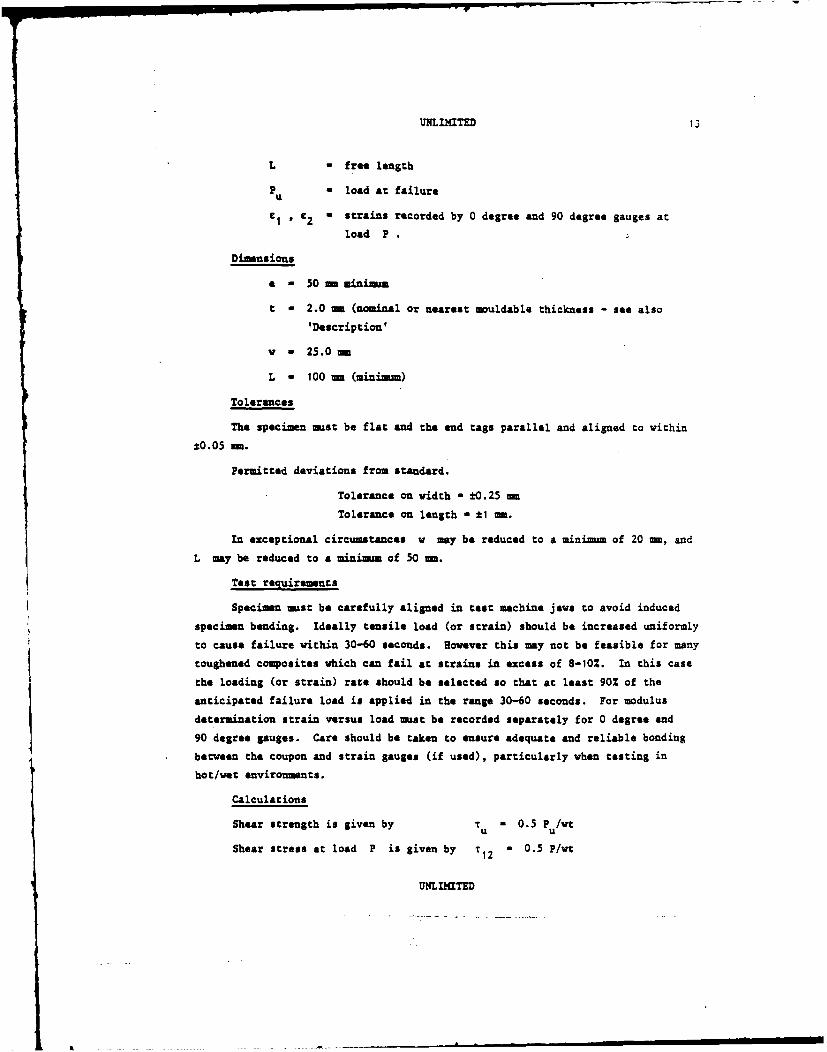
UNLMITED 13
L - free length
P - load at failureu
eI , €2 a strains recorded by 0 degree and 90 degree gauges at
load P
Dimensions
a - 50 mm minimum
t - 2.0 ae (nominal or nearest mouldable thickness - see also
'Description'
v a 25.0mm
L - 100 me (minimum)
Tolerances
The specimen must be flat and the end tags parallel and aligned to within
*0.05 M.
Permitted deviations from standard.
Tolerance on width a *0.25 mm
Tolerance on length V *1 me.
In exceptional circumstances w may be reduced to a minimum of 20 ma, and
L may be reduced to a minimum of 50 m.
Test requirements
Specimen mast be carefully aligned in test machine jaws to avoid induced
specimen banding. Ideally tensile load (or strain) should be increased uniformly
to cause failure within 30-60 seconds. However this may not be feasible for many
toughened composites which can fail at strains in excess of 8-10%. In this case
the loading (or strain) rate should be selected so that at least 90% of the
anticipated failure load is applied in the range 30-60 seconds. For modulus
determination strain versus load must be recorded separately for 0 degree and
90 degree gauges. Care should be taken to ensure adequate and reliable bonding
between the coupon and strain gauges (if used), particularly when testing in
hot/wet environments.
Calculations
Shear strength is given by T - 0.5 P /wtU u
Shear stress at load P is given by T 12 - 0.5 P/wt
UNLIITED

14 UNLIMITED
Shear strain at load P is given by Y12 C I - C2
Since stress versus strain graph may be nonlinear, shear modulus isdefined as:
G 12 a secant modulus at 0.51 shear strain (1)
Report shear strength and modulus, stress versus strain curve to failure,
actual moulded thickness, nominal thickness Vf .
NOTES: (1) For mthod of derivation see Part 0 - Introduction.
(2) Creep my occur at high stress levels, particularly at elevated
temperature, rendering the strain values time dependent.
(3) Rail shear test (Ref ARC CP1381) may be used as an alternative
for shear strength measurement only.
UNLIMITED
t . . ...... . . ..... . . ." - -- J JI I

UNLIMITED l
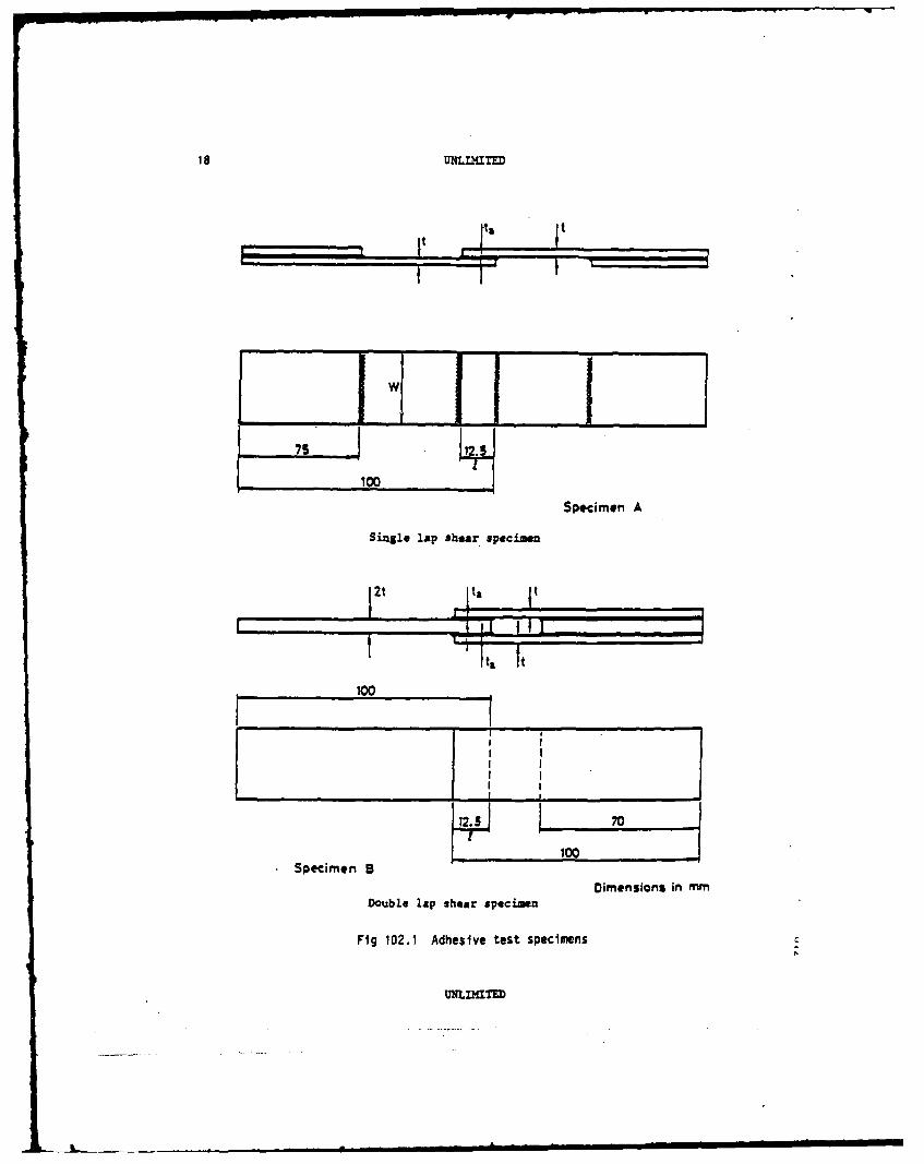
102 METIOD OF TEST FOR LAP SEAR STRENGTH OF FIBRE REINFORCED PLASTICS
Description
These specimens are used for comparative tests on adhesives used for bonding
laminated composite materials, and not to obtain design data on adhesive proper-
ties nor strength data for specific applications (see Note). The single lap
specimen A would normally be used for quality control tests, whilst either
specimen A or the double lap specimen B may be used for comparative testing, eg
() to compare the adhesion shear strength obtained with different
adhesives;
(ii) to study the influence of surface preparation;
(iii) to study the influence of fibre orientation in the surface layers
at the bonded surfaces;
(iv) to study the influence of environmental effects.
Specimen B would normally be expected to give the higher average shear
stress at failure because of inherently lover peel stresses at the ends of the
joint.
Tn each series of comparative tests, only the parameter under investigation
should be varied, all other parameters remaining constant throughout.
Note that the size and quality of. the adhesive fillet can affect the test
result.
The adherends may be made from unidirectional tape or woven material
provided the laminate is axially orthotropic to obviate induced bending.
The specimens are illustrated in Fig 102.1
NOTE: For the derivation of design data on the cohesive properties of
adhesives, the test method given in Draft European Standard Aerospace
Series pr EN 2243-6 should be used.
The average shear stress in a joint at failure is a function of the overlap
length, the stiffness of the adherends, the stress versus strain character-
istics of the adhesive and the level of peel stresses at the ends of the
joint. Therefore, to obtain design strength data for a specific appli-
cation, a fully representative cast specimen must be used.
UNLIITED

16 UMLMXTED
Nomenclature
t a thickness of adherends
t a thickness of adhesive
v a width of specimen
1 overlap length of joint
P a load at failure
ave- man shear stress in joint at failure.
Dimens ions
t a 2.0 to 2.5 m, depending on laminate configuration
v - 25 -
1 - 12.5 -.
Permitted deviations from the standard
For particular purposes:
t may be between 1.2 and 3.0 mm
w ma be between 17 and 30 m but not less than lOt.
Tolerances
All edges must be square and the sides of the specimens must be parallel
to within *0.05 me.
The adherends must be flat and of uniform thickness to within ±0.05 m.
The adhereands must be parallel with a uniform thickness of adhesive to
within *0.025 m.
Overlap length shall be accurate to *0.25 me.
Ideally it is recommnded that the moisture content of the adherends be
kept as low as possible.
Test requirements
The test specimen must be carefully aligned in the jaws of the test machine
to avoid induced bending.
Tensile load should be increased uniformly to cause failure within
30-90 seconds.
UNLIITED

UNLIMITED 17
When environmental conditioning is required it should be undertaken on the
complete specimen after uanu acture.
Calculations
The mean shear stress at failure is given by:
Tave a P/wl (specimen A)
Sa'M W P/2vl (specimen B)
accurately measured values of v and 1 mist be used.
Report mean shear stress at failure, mode of failure (cohesive adhesive,
or delamination), adhesive type, measured bond line thickness, laminate con-
figuration including orientation of surface layers, and surface preparation of
adherenda.
Validity
All shear modes of failure are valid results. (The maximum achievable
shear stress will be obtained with cohesive failure within the adhesive.)
UNLIMTED
I IIIIIII iL l I i. !• ...
100HSpecimen A
Sinagle lap shear specimen
1i " I
100
II I
SI
Sp ci5 o . 8 100.
Sp1 Dimensions in mm
Double lap shear specimaen
SAdhesive test specimens
UNIDaTED

UNLIMITED 19
200 METHOD OF TEST FOR FLEXURAL STRENGTH AND MODULUS OF FIBRE REINFORCEDPLASTICS
,. -It
Fig 200.1
Description
This is a three-point flexure cest for reinforced plastic specimens with
span to depth ratio high enough to produce bending failure.
Materials
The test may be used for either unidirectional or woven material. The
material direction under investigation must be orientated along the specimen
length.
Nomenclature
t - specimen thickness w - specimen width
S - span between supports P a load at failure
known to *0.21
m - slope of linear load/deflection graph (N/m)
Dimensions
t 2.0 mi- (or nearest w - 10.0 me *0.25 mmouldable thickness)
Table of Span Requirements
Composite reinforcement Alignment of fibresto beam axis
Unidirectional carbon fibre 0 degree 40/IUnidirectional carbon fibre 90 degrees 25/1Woven carbon fibre 0 degree/90 degrees 25/1
Unidirectional glass fibre 0 degree 20/1 *1 mUnidirectional glass fibre 90 degrees 20/1Woven glass fibre 0 degree/90 degrees 20/1Woven aramid fibre 0 degree/90 degrees 16/1
UNLIMITED
L - . ... = i mi. I ~

20 L alLTED
Minimum overhang of specimen beyond rollers 5.0 m
Support rollers 10 me diameter
Loading roller 25 ma diameter
Loading roller to be located at aid-span within tO.5 ms.
The diameter of the support rollers may be reduced to a minimum of 6 m,.
The diameter of the loading roller may be reduced to a minimum of 10 mm.
(The larger diameter rollers are recommended to prevent specimen indentation.)
Tolerances
Width and thickness shall be uniform to within 0.05 me.
Test requirements
A jig should be used to ensure accurate alignment. Load should be increased
uniformly to cause failure within 30-180 seconds. Central deflection versus load
must be recorded if flexural modulus values are required.
Calculations
Flexural strength is given by:
2fir a 1.5 PS/vt
Flexural modulus is given by
S- S3m/4w3
Values of w and t must be obtained by accurate measurement at the middle
of the specimen.
Report flexural strength and modulus, Vf , nominal and actual thickness.
Validity
The flexural test is primarily for material control purposes and will not
provide reliable tension or compression data. The test results will depend upon
the actual fibre volume fraction (Vf) of the laminate.
C
UNLITED
UNLIMITED 21
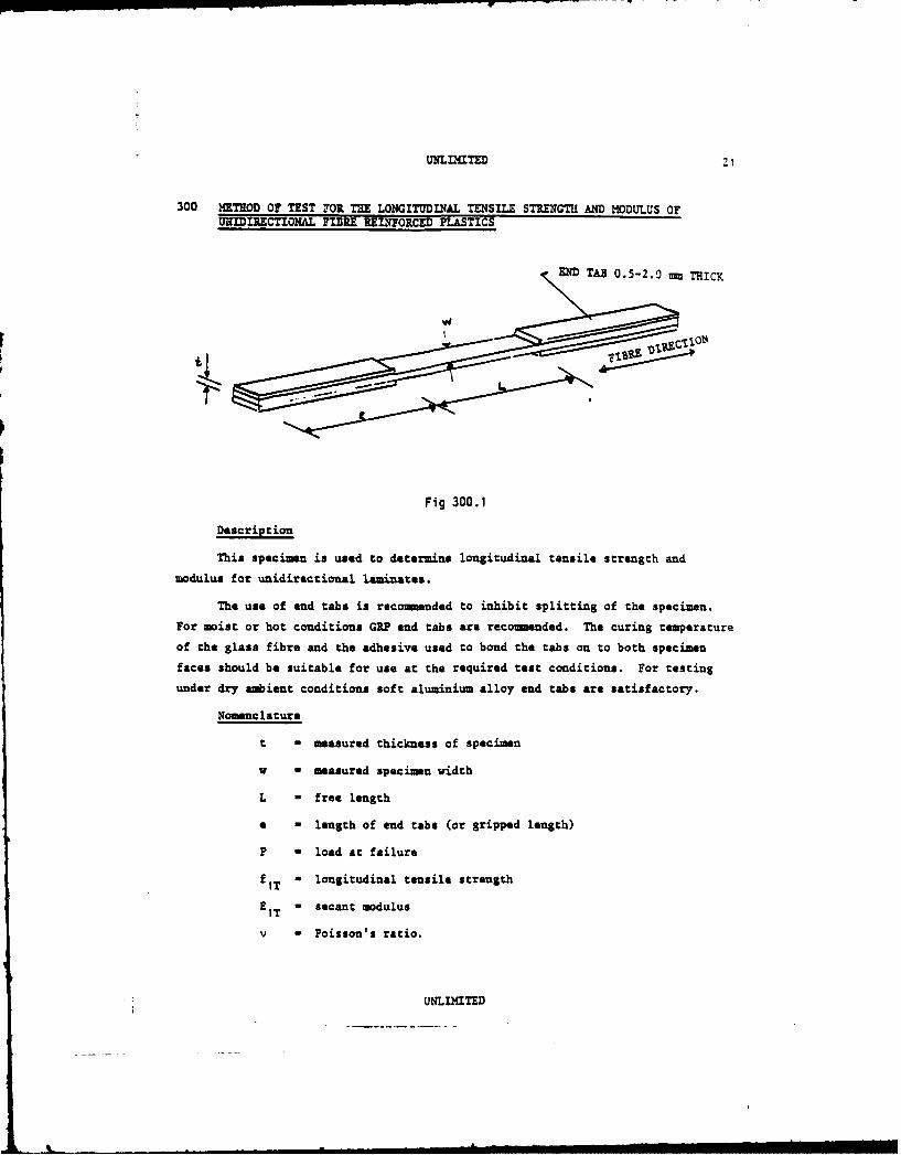
300 METIOD OF TEST FOR TE LONGITUDINAL TENSILE STRENGTI1 AND MODULUS OFURIDIRECTIONAL FIBRE RELITORCED PLASTICS
END TAB 0.5-2.0 THICK
Fig 300.1
Description
This specimen is used to determine longitudinal tensile strength and
modulus for unidirectional laminates.
The use of end tabs is recommended to inhibit splitting of the specimen.
For moist or hot conditions GRP and tabs are recommended. The curing temperatureof the glass fibre and the adhesive used to bond the tabs on to both specimen
faces should be suitable for use at the required test conditions. For testing
under dry ambient conditions soft aluminium alloy end tabs are satisfactory.
Nomenclature
t - measured thickness of specimen
v a measured specimen width
L = free length
a - length of end tabs (or gripped length)
P - load at failure
fIT o longitudinal tensile strength
EIT " secant modulus
v a Poisson's ratio.
UNLIMITED

22 t,,NLaTED
Dimensions
t - 1.0 m* (nearest mouldable thickness)
w - 10-20 m
L - 100-150 mm
5 50 M minium.
* Tolerances
Width and thickness mast be uniform to *0.04 am.
Specimen profiles including end tabs mat be symmtric about longitudinal
axis to *0.05 m.
Fibre alignment must be parallel with the specimen longitudinal axis
within 00 30'.
Test requiremints
Specimens mast be carefully aligned in test machine jaws to avoid induced
specimen bending. Tensile load (or strain) should be increased uniformly to
cause failure within 30-90 seconds. For modulus determination axial strain
versus load mast be recorded. (Transverse strain measurements are also required
if Poisson's ratio is to be determined.)
CalculationsP
Longitudinal tensile strength is given by fiT P
Accurately measured values of w and t mast be used.
The stress versus strain graph is frequently nonlinear. with modulus
changing slowly with increasing strain. It may be required to use all the data
generated right up to failure, ag for laminate strength prediction. Usually,
however, a spot value is specified for general design use, longitudinal tensile
modulus being defined as either:
EIT a secant modulus at S% longitudinal strain
or
100 (stress at S1% lou. strain - stress at S2% long. strain)EIT I 2
Similarly Poisson's ratio may be defined as either:
V a transverse strain at SZ longitudinal strain Clongitudinal strain
UNLDaITED

UNLIITED 3
or- 100(trans strain at S1% long strain - trans strain at 52% long strain)
S - S2s1 " 2
The values of S , SI and S2 can vary with material characteristics andproject requirements. In the absence of such pointers, it is recommended thatthe simpler definition is followed with S - 0.25, as described in the Introduction
section 0.
NOTE: The properties derived will be approximately proportional to the
fibre volume fraction of the laminate.
Report longitudinal tensile strength and modulus, stress versus strain curveto failure, Poisson's ratio, Vf , nominal and actual thickness.
Validity
To be valid for design data, failure must occur in the central region.
UNLIMITED
24 UNLIMITED
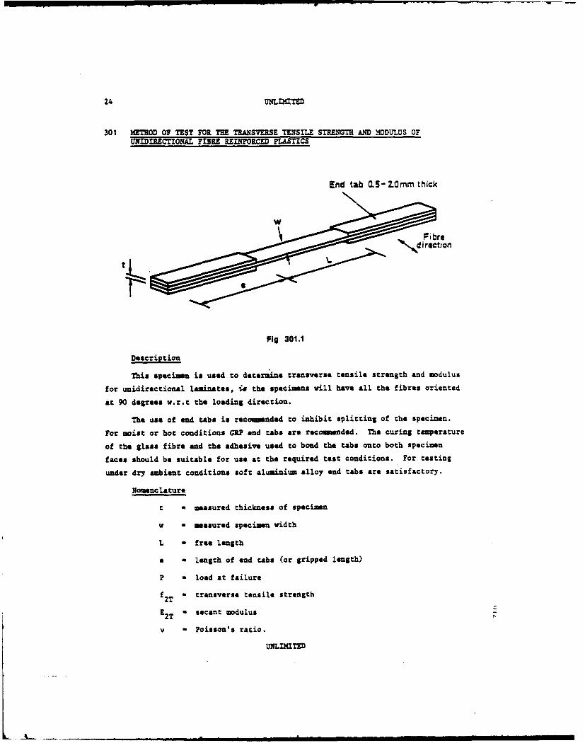
301 kTHOD OF TEST FOR THE TRANSVERSE TENSILE STRENGTH AND Mi0DULUS OFUNIDIRECTIONAL FIBRE rINFORCED PLA STICS
End tab 5 - 2.0rm thick
Fig 301.1
Description
This specimen is used to determine transverse tensile strength and modulus
for unidirectional laminates, is the specimans will have all the fibres oriented
at 90 degrees w.r.t the loading direction.
The use of end tabs is recomaded to inhibit splitting of the specimen.
For moist or hot conditions GRP end tabs are recomnnded. The curing temperature
of the glass fibre and the adhesive used to bond the tabs onto both specimen
faces should be suitable for use at the required test conditions. For testing
under dry ambient conditions soft aluminium alloy end tabs are satisfactory.
Nomenclature
t a measured thickness of specimen
v a measured specimen width
L a free length
a - length of end tabs (or gripped length)
P M load at failure
f2T = transverse tensile strength
E " secant modulus2T z
V a Poisson's ratio.
UNLIMTED

UNLIMITED -D
Dimnsions
t - 2.00 mm* (nearest mould,ble thickness)
v - 10-20 mm
L - 100-150 mm
e - 50 m miniMIm.
* Tolerances
Width and zhickness must be uniform to *0.04 mm.
Specimen profiles including end tabs must be symmetric about longitudinal
axis to *0.05 mm.
Fibre alignment mst be parallel with the specimen longitudinal axis
within 0° 30'.
Test requirements
Care should be taken when cutting blank coupons from the panel to minimise
edge damage induced by cutting, since this can influence the measured strengths.
Specimen must be carefully aligned in test machine jaws to avoid induced
specimen bending. Tensile load (or strain) should be increased uniformly to
cause failure within 30-90 seconds. For modulus determination axial strain versus
load must be recorded. (Longitudinal strain measurements are also required if
Poisson's ratio is to be determined.)
Calculations
Transverse tensile strength is given by f2 "
Accurately measured values of w and t must be used.
Since the stress versus strain graph is frequently nonlinear, the transverse
tensile modulus is defined as either:
E2T - secant modulus at SZ transverse strain
or
E " 100 (stress at S1% trans. strain - stress at S2% trans. strain)2T S-
Similarly Poisson's ratio may be defined as either
- longitudinal strain at SZ trans straintransverse strain
UNLIMITED

26 UNLLMITED
or
V- 100(long. strain at S1Z trans. strain - long. strain at S2Z trans. strain)S I - S 2
The values of S , SI and S2 can vary with material :haracteristics and
project requirements. In the absence of such pointers, it is recommended that
the simpler definition is followed with S - 0.25, as described in the Introduction
section 0.
Report transverse tensile strength and modulus, stress versus strain curve
to failure, Poisson's ratio, Vf
Validity
To be valid for design data, failure must occur in the central region.
UNLIMITED

302 METHOD OF TEST FOR THE TENSILE STRENGTH AND MODULUS OF MULTIDIRECTIONALFIBRE REINFORCED PLASTICS
END TAB 0.5-2.0 n THICK
Fig 302.1
Description
This specimen is used to determine the tensile strength and modulus of
multidirectional laminates (unmotched). The test may be used for either uni-
directional tape or woven materials, provided the laminate is axially orthotropic
to obviate induced bending.
In the angled plies, no individual fibres should run under the tabs at both
ends of the specimen. The free length is chosen so that a non-axial fibre can
run across the full width of the specimen and be at least half its specimen
width short of the end tabs at each end, is minimum L - W I + I-- .
For testing under dry ambient conditions soft aluminium alloy or GRP end
tabs are suitable. For moist or hot conditions GRP end tabs are recomended.
The tabs are attached using an adhesive suitable for the test environment.
The end tab adhesive shear strength will limit the level of load input and
hence limit the amount of 00 fibres present in the laminate, eg typically for
tests under dry ambient conditions a maxima thickness of 1.5 am of 00 carbon
fibres can be alloyed.
In exceptional circumstances testing without end tabs may be permissible
provided that suitable end grips are used.
UNLIMITED

28 U TMITED
Nomnclature
a - length of end tabs
t - measured thickness of specimen
v a measured width of specimen
L a free length
6 - angle between fibres and longitudinal axis
P - load at failure.
Dimensions
a - 50 a minimum
w - 9t minimu, typically lOt (absolute minimum 20 m)
t - 1.0 to 4.0 am depending on laminate configuration
L not less than v(l + 1/tan e) or 100 *1 mu whichever is greater.
Tolerances
Edges of specimen must be parallel to *0.1 mm. Specimen must be flat and
end tab faces parallel and aligned to within *0.05 mM.
For small angles of 8(<150) L may be reduced to w/tan e
Test requirements
Specimen must be carefully aligned in test machine jaws to avoid induced
specimen bending. Tensile load (or strain) shall be increased uniformly to cause
failure within 30-90 seconds. For modulus determination strain versus load must
be recorded.
Calculations
Tensile strength for plain specimen is given by:
P
T Vt
Since stress versus strain graph may be nonlinear, tensile modulus is
defined as:
ET - secant modulus at 0.25% axial strain (1)
Poisson's ratio transverse strain at 0.25% axial strain (1)
axial strain
UNLIMTED
A - .... .... . . - .- - . ,, ' --- L- am m mlm iI

UNLIMITED Z9
NOTE: (1) For method of derivation see Introduction, section 0.
Report tenaile strength and modulus stress versus strain curve to failure,
actual moulded chickness, actual and nominal thickness and Vf
Validity
To be valid for design data, failure of the plain specimen must occur in
the central region. If the damage extends into the end tab region the result
will provide only a lower bound strength value.
UNLIMITED

30 UNLnaITs
303 METHOD OF TEST FOR THE NOTCHED TENSILE STRENGTH OF MLTIDIRECTIONALFIPn REINFORCED PLTICS
HO.I FORNOTCX SEITIVTY END TAB 0.5-2.0 mm THICK
Fig 303.1
Description
This specimen is used to determine the notch sensitivity in tension of
muItidirectional laminates. The test may be used for either unidirectional tape
or woven materials, provided the laminate is axially orthotropic to obviate
induced bending. For basic strength and stiffness measurement a plain specimen
is used (see Data Sheet 302). For comparative tests a specimen with a 5.0 mm
diameter hole drilled at its centre has become standardised.
In the angled plies, no individual fibres should run under the tabs at bothends of the specimen. The free length is chosen so that a r on-axial fibre can
run across the full width of the specimen and be at least half its specimen
width short of the end tabs at each end, ie minimum L - v(1 + 1/tan 8)
For testing under dry ambient conditions soft aluminium alloy or GRP end
tabs are suitable. For moist or hot conditions GRP end tabs are recomended.
The tabs are attached using an adhesive suitable for the test environment.
The end tab adhesive shear strength will limit the level of load input and
hence limit the amount of 00 fibres present in the laminate, eg typically for
tests under dry ambient conditions a maximum thickness of 1.5 - of 00 carbon
fibres can be allowed.
UNLIMITED

UInIaTED 31
Testing without end tabs is permissible provided that suitable end grips
are used.
amosnc lature
a - length of end tabs
t - measured thickness of specimen
d - measured hole diameter
L - free length
0 - angle between fibres and longitudinal axis
P - load at failure.
Dimensions
Table 303.1
Reco =ended coupon widths
d wm m
>4.0 30'>4.0 to 5.0 35>5.0 to 6.0 40>6.0 to 7.0 45 , tO.25>7.0 to 8.0 50>8.0 to 9.0 55>9.0 to 10.0 60>10.0 6d,
Holes may be filled with plain or C/S rivets or bolts.
e - 50 mm minimam
t = 1.0 to 4.0 om depending on laminate configuration
L not less than w(l + 1/tan 8) , 2.5w or 100 mmn whichever is
the greatest.
For particular purposes other hole sizes, or filled holes with plain or C/S
rivets or bolts may be used. A miniuzm v/d ratio of 6 is permissible.
For smll holes (<4.0 ms) w may be reduced to between 20 mm and 30 -
provided that w is not less than lOt and 7d.
For small angles of e(<5 ° ) L may be reduced to v/tan 8
UNLITED

32 Ummn TED
Tolerances
Edges of specimen must be parallel to *0.1 mm, specimen must be flat and
end tab faces parallel and aligned to within *0.05 mam.
Hole must be symmetrical about specimen width to *0.1 mm.
Test requirements
if rivets are used they should be formed by the normal manufacturing
process.
If bolts are used, a standard washer should be fitted under the nut, which
should then be tightened to the normal manufacturing controlled torque level.
The specimen must be carefully aligned in test machine jaws to avoid
induced specimen bending. Tensile load (or cross-head displacement) should be
increased uniformly to cause failure within 30-90 seconds.
Calculations
Tensile strength for notched specimen (based on gross area) is given by:
f PNT ZE
Report notched tensile strength, actual moulded thickness, and nominal
thickness and Vf
Validity
To be valid for design data, failure of the specimen ast occur in the
central region.
u aUNIIE

UNLIMITED 33
400 MZTHO OF TEST FOR LONGITUDINAL COWRESSION STRENGTH AND MODULUS OFUNIRICTONAL FIBRE REINFORCED PLASTICS
Description
This Data Sheet defines the recommuded mehod for measuring the longi-
tudinal compression strength and modulus of a unidirectional laminate. After
initial discussion by the group two methods were proposed but subsequent testing
and investigation has led to the recommendation of a Celanese type specimen which
is shown in Fig 400.1
10
ALL DIMNS IONS
0.
END PLATES0.5-2.0LIGT ALLOYOR GPP
Fig 400.1 Unidirectional compression specimen
The specimen may be tested in a modified Clanese jig (based on ASTM
D3419/75) for lateral restraint (eg see RAE TR 82047), or in a machine capable
of maintaining accurate alignment and rotational restraint through the end
fixtures.
UNLIMITED

34 UNIMfITED
The gauge length is 10 ma which is a compromise between the requirement to
eliminate Euler buckling and the need to avoid end tab effects whilst providing
adequate space for strain gauges.
The longitudinal modulus may be obtained from the strength test if the
specimen is strain gauged. It is recomended that gauges be applied to both
sides of the specimen in order to detect any Euler bending or loading
eccentricity.
Nomenclature
t - measured thickness at specimen centre
w - measured specimen width
G.L. - gauge length
L M length of composite specimen
P a load at failure.
Dimensions
t - 2.00 a or nearest mouldable thickness
V - 10.00 ± 0.25 m
G.L. - 10.00 t 0.25 mm
L - 110 R.
Fibre alignment 00 ±30 seconds (relative to the specimen longitudinal axis).
Tolerances
Edges of specimens must be parallel to *0.1 mm. Specimen must be flat and
end tab faces parallel and aligned to within ±0.05 ma.
Test requirement
Compression load (or strain) should be increased uniformly to cause failure
within 30-90 seconds.
Since some specimen bending may occur the average of the two surface strains
must be taken as the axial strain.
Care must be taken during specimen manufacture because it is possible for
end tab and glue line tolerances to accumulate and produce eccentric loading in
the specimen.
UNLIMITED

UNLIMITED 35
Extreme care must be taken with specimen alignment in the machine to avoid
off fibre-axis loading.
Calculations
Longitudinal compression strength is given by FLC -P .
Accurately measured values of w and t must be used.
Since the stress versus strain graph is nonlinear, the compression modulus
is defined as:
EiC a secant modulus at -0/251 strain (I), (2).
Stransverse strain at -0.25% strain (2).Poison rato - axial strain
NOTES: (1) The properties derived will be proportional to the fibre
volume fraction of the laminate.
(2) For method of derivation, see Introduction section 0.
Report compression strength, modulus, stress versus strain curve to failure,
fibre volume fraction (Vf) and width and actual and nominal thickness.
Validity
To be valid design strength data, failure must occur near the middle of
the gauge length. Otherwise, the result will provide only a lower bound value.
UNLIMITED
36 UNLLMITD
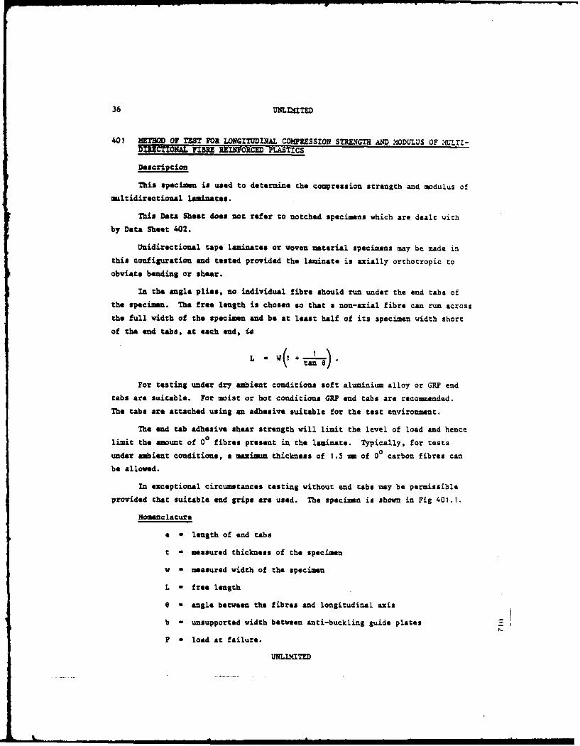
401 WM=T OF TEST FOR LONGITUDINAL COMPRESSI0N sTRENG AND NIODULUS OF \OLTL -
D ECTIONAL FIBRE REINFR0CED PLASTICS
Description
This specimen is used to determine the compression strength and modulus of
multidirectional laminates.
This Data Sheet does not refer to notched specimens which are dealt with
by Data Sheet 402.
Unidirectional tape laminates or woven material specimens may be made inthis configuration and tested provided the laminate is axially orthotropic to
obviate bending or shear.
In the angle plies, no individual fibre should run under the end tabs of
the specimen. The free length is chosen so that a non-axial fibre can run across
the full width of the specimen and be at least half of its specimen width short
of the end tabs, at each end, is
For testing under dry ambient conditions soft aluminium alloy or GRP endtabs are suitable. For moist or hot conditions GRP end tabs are recommended.
The tabs are attached using an adhesive suitable for the test environment.
The end tab adhesive shear strength will limit the level of load and hence
limit the amount of 00 fibres present in the laminate. Typically, for tests
under ambient conditions, a maximum thickness of 1.5 mm of 00 carbon fibres can
be allowed.
In exceptional circumstances testing without end tabs may be permissible
provided that suitable end grips are used. The specimen is shown in Fig 401.1.
Nomenclature
e - length of end tabs
t - measured thickness of the specimen
v - measured width of the specimen
L - free length
e - angle between the fibres and longitudinal axis
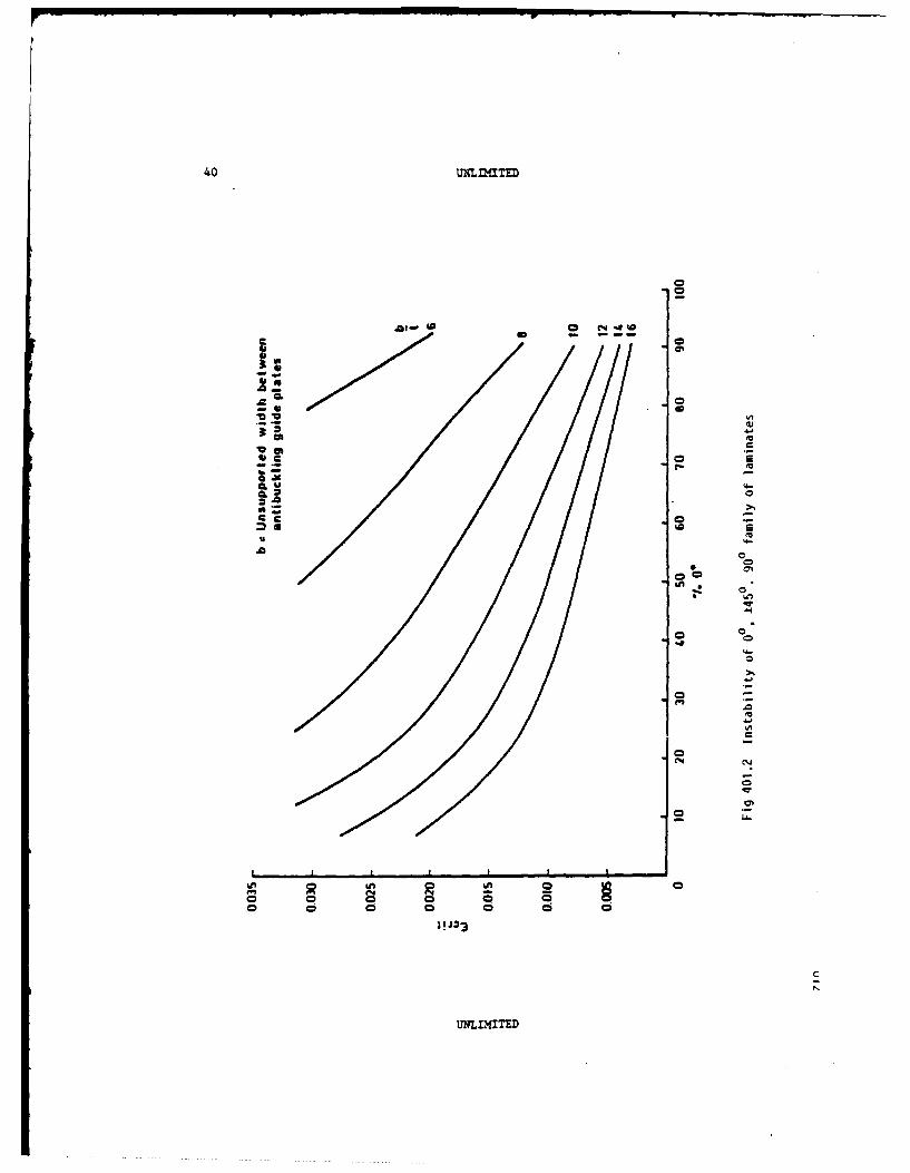
b - unsupported width between anti-buckling guide plates
P - load at failure.
UNLIMITED

UNLflaTED3
Dimensions
v - 9t minimum, typically 10t (absolute minimum - 20 m)
a - 40 - minimum
t a 2.00 to 4.00 mm depending on laminate configuration
b - see under Test requirements
- not less than w(1 ) or 100 mm whichever i3 the greatest.
Tolerances
The edge of the specimen must be parallel to within *0.1 mm. Tolerance on
thickness, *0.05 ma.
The specimen must be flat and end tab faces parallel and aligned to within
.t0.05 MR.
For small angles of e(<15 ° ) L may be reduced to w/tan 6
Test requirements
The specimen must be carefully aligned in the test machine, and suitable
anti-buckling guides employed. These guides should support as much of the
specimen free length as possible, allowing for axial deformations, and should
provide restraint against out-of-plane displacements at the ends to prevent local
failure within the unsupported length. The distance 'b' between guide plates
should ensure that the critical strain 'Ecrit' at which instability buckling
may occur, as indicated in Fig 401.2, is always greater than the strain at which
laminate compression failure is anticipated. The greater the margin of safety
the less the possibility of premature instability induced failure. Whilst the
guides are intended to support the specimen against out-of-plane deflection, care
must be taken to avoid clamping friction and also any constraints to free
Poisson's deformations across the width of the specimen. Forms of anti-buckling
guides are shown in Figs 401.3 and 401.4.
Compressive load (or strain) shall be increased uniformly to cause failure
within 30-90 seconds. For modulus determination the stress versus strain curves
to failure must be recorded.
Calculations
Longitudinal compression strength is given by:
F ' P
LC = t
UNLIMTED

38 uLZ)aTE
Accurately measured values of v and t mist be used.
Since the stress versus strain curve is nonlinear, compression modulus is
defined as:
EKC - secant modulus at -0.25Z strain (1)
Poisson's ratio - transverse strain at -0.25% strainaxial strain
NOTE: (1) For method of derivation see introduction section 0.
Report compression strength, compression modulus, stress versus strain
curves, fibre volume fraction (Vf), nominal and actual moulded thickness.
Validity
To be valid for design data failure of the specimen must occur in the
central region. I the damage extends into the end tab region the result will
provide only a lover bound strength value.
|N
UNLIMITED

UNLflITED 39
-t
LED TABSO.S-2.0 WLIET ALLOY
OR GRP
Fig 401.1 Multidirectional laminate: compressior,
strength and modulus specimen
UNL...TED
00
- -.2.!
0
0 0
w.'Z.
;!J=3
Uc4-

UNLLZTIED
E
Specimen
Body plate
End plate spacer ,L - i
-- I"thickness spacer +1
PTFE
II
I .IIII I
iIL, I IT
Steel shim(a compressedPTFE thickness)
Fig 401.3 Anti-buckling guide
UNLIMITED
-.- ______

42 UNLIMITED
J 0)
UOU
Fig 401.4 Anti-buckling guide
UNLIMITED

UNLaTE
402 METHOD 0 TEST FOR NOTCHED COMPRESSION STRENGTH OF MULTIDIRECTIONALFIBRE REINFORCED PLASTICS
Description
This specimen is used to determine the compression strength of notched
multidirectional laminates. In order to assess notch sensitivity, on a compara-
tive basis, a speamen with a 5sm diameter hole drilled at its centre is used.
Unidirectional tape laminates or woven material specimens may be made and
tasted in this configuration provided that the laminate is axially orthotropic
to obviate induced bending or shear.
In the angle plies, no individual fibres should run under the end tabs of
the specimen. The free length is chosen so that a non-axial fibre can run across
the full width of the specimen and be at least half specimen width short of the
end tabs, at each end, ie
For testing under dry, ambient conditions, soft aluminium alloy or GRP end
tabs are suitable. For moist or hot conditions GRP end tabs are recomended.
The tabs are attached using an adhesive suitable for the test environment.
The end tab adhesive shear strength will limit the level or load input and
hence limit the amount of 00 fibres present in the laminate, eg typically for
tests under dry ambient conditions a maximum thickness of 1.5 m of 0 carbon
fibres can be allowed.
Testing without end tabs is permissible provided that suitable end grips
are used.
The specimen is shown in Fig 402.1.
Nomenclature
a - length of end tabs
t - measured thickness of the specimen
w - measured width of the specimen
L - free length
d = hole diameter
e - angle between fibres and longitudinal axis
UmLIITED
44 UlI .TED
P - load at failure
b - unsupported width between anci-buckling guides.
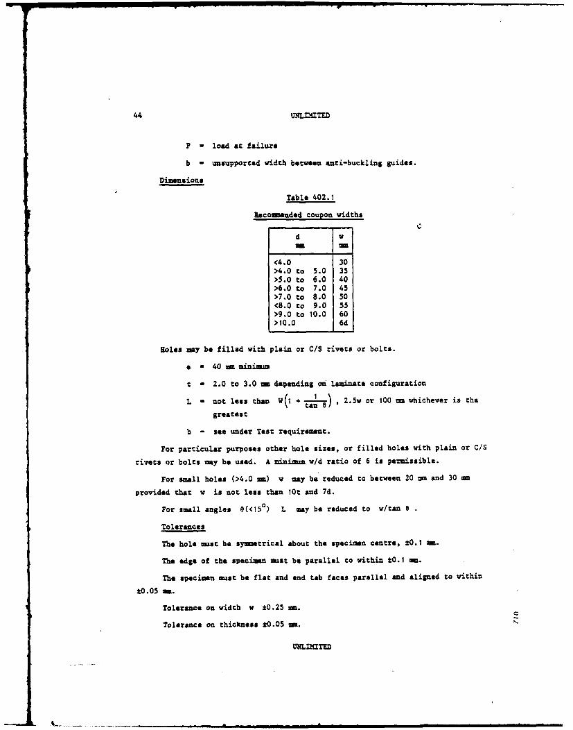
Dimensions
Table 402.1
Recommended coupon widths
d v-m me
<4.0 30>4.0 to 5.0 35>5.0 to 6.0 40>6.0 to 7.0 45>7.0 to 8.0 50<8.0 to 9.0 55>9.0 to 10.0 60>10.0 6d
Holes may be filled with plain or C/S rivets or bolts.
• - 40 mm minimu
t a 2.0 to 3.0 mm depending o laminate configuration
L a not less than W(1 + '-) , 2.5w or 100 = whichever is the
greatest
b - see under Test requirement.
For particular purposes other hole sizes, or filled holes with plain or C/S
rivets or bolts may be used. A minim um w/d ratio of 6 is permissible.
For small holes (>4.0 me) w may be reduced to between 20 m and 30 mm
provided that w is not less than 10t and 7d.
For small angles 8(<15 0 ) L may be reduced to v/tan 8
Tolerances
The hole -=st be syetrical about the specimen centre, t0.1 mm.
The edge of the specimen must be parallel to within *0.1 me.
The specimen must be flat and end tab faces parallel and aligned to within
*0.05 me.
Tolerance on width w ±0.25 -m.
Tolerance on thickness *0.05 mm.
UNLIITED

UNLIMITD-
Test requirements
If rivets are used they should be formed by the normal manufacturing
process.
If bolts are used, a standard washer should be fitted under the nut, which
should then be tightened to the normal manufacturing controlled torque level.
The specimen must be carefully aligned in the test machine and a suitable
anti-buckling guide employed (see Data Sheet 401).
NOTE: that compression load (or cross-head displacement) should be increased
uniformly to cause failure within 30-90 seconds.
Calculations
Notched, longitudinal compression strength is given by:
F--- "P (based on gross area)
Accurately measured values of w and t mast be used.
Report compression strength, fibre volume fraction (Vf), nominal and actual
moulded thickness.
Validity
To be valid for design data, failure of the specimen mast occur in the
central region. If the damage extends into the end tab region the result will
provide only a lower bound strength value.
UNLIMITED

46 UN~nTED
w
.-
End tabs0.5 -2.0mmlight alLoy
Fig 402.1 Multidirectional laminate: notchedcompression, strength specimen
UNIMTED

UNLLIXITED d7
403 HETHOD OP TEST FOR RESIDU L CMPRESSION STRE GTH AFTMR INACT OF MULMTI-
DIRCTIONAL FIBRE REINTORCED PLASTICS
Description
This test method shall be used to determine the residual compressive
strength of fibre reinforced plastics after impact damage.
The laminate thickness, ply orientation, specimen size and method of impact
have been standardised for comparative purposes. For specific applications other
laminate configurations and types of indentor may be used.
The tests shall be carried over in two stages:
(a) impacting the laminate over a range of energy levels and monitoring
the type and size of damage produced (see Method 1001),
(b) testing damaged compression specimens cut from the test laminate to
determine residual compressive strength.
Test laminate
The test laminate shall be quasi-isotropic (25%: 0°, 25%: 900 , 50%: ±45
°)
and of the nearest moulded thickness to 3 mm. For unidirectional tapes of cured
ply thickness 0.125 mm the lay-up shall be (.45, -45, 0, 90)3S.
Impact tests
A suitable impact rig shall be used consisting of a drop-weight impacting
onto the centre of an area of the test laminate securely clamped between two
steel rings (see Fig 403.1). The clamp shall be designed to minimise the effect
of uneven pressure distribution on the clamped area and shall be positioned on a
solid non-energy absorbing surface.
The drop-weight shall consist of a mass with a steel ball or hemispherical
indentor of radius in contact with the laminate d/2. The indentor shall be of
800 VPN minimum hardness and of surface finish less than 0.5 microns. The
indentor shall be replaced at the first sign of damage or flattening.
The test laminate shall be impact damaged prior to being cut into com-
pression specimens. The impacting of individual specimens shall not be allowed.
The drop-weight shall be released from the height (h) ensuring that it
strikes the laminate at the centre of the clamped area. This may be achieved by
the use of guides provided that frictional effects are negligible. The weight
shall be caught on the rebound to prevent secondary damage to the laminate after
initial impact.
UNLIMITED

48 UNLIXTED
The impacting of the laminate shall be carried out over a range of energies.
The impact energy shall be adjusted by changing the mass of the drop-weight and
keeping the height (h) constant. Each impact of the laminate shall be carried
out in a now undamaged position. The contras of any damage positions shall not
be closer than 100 ma to each other and to the edge of the laminate.
The axtent and type of damage (ag delamination, splitting, fibre failure or
penetration) shall be assessed visually and with the aid of ultrasonic inspection
techniques (Method 1001). The impact energies at which damage first occurs
(damage threshold) and at which damage is first visible to the naked eye on the
laminate top surface, shall be recorded.
Areas of damage of width 40 ma or greater shall not be used for residual
compressive strength testing. Any splitting of the lower outer ply of the
laminate may be ignored provided the central delaminated area does not exceed
40 ma in width.
Compression tests
Compression specimens (see Fig 403.2) shall be cut from the laminate
ensuring that the damaged area lies in the centre of the specimen.
For testing under dry ambient conditions soft aluminium alloy or GRP end
tabs are suitable. For moist or hat conditions GRP end tabs are recomended.
The tabs shall be attached to the specimens using an adhesive suitable for the
test environment. Testing without end tabs is permissible provided that suitable
and grips are used.
The specimen shall be carefully aligned in the test machine and a suitable
anti-buckling guide employed (see Data Sheet 401). Compression load (or cross-
head displacement) shall be increased uniformly to cause failure within
30-90 seconds.
Nomenclature
a - length of end tabs
h - drop height from indentor tip to the laminate surface in
metres
M - measured mass of drop-weight in kg
U - impact energy in Joules
d - indentor diameter
unna=T

UNLfLMITED
D, a clamping ring innder diameter
D2 clamping ring outer diameter
t a measured thickness of specimen
w - measured width of specien
L free length of specimen
b a unsupported width between anti-buckling guides
P - load of failure.
Dimensions
a a 40 sm minizum
h " 1
H - as required
d - 1O am
DI M 100M
D2 - 140 m
t a 3 mm or nearest moulded thickness
w - 50 um
L - 100m
b - 40mi
Tolerances
The impact point shall coincide with the specimen centre line to within
The edge of the specimen shall be parallel to vithin *0.1 mm.
The specimen shall be flat and end tab faces parallel and aligned to
within *0.05 min.
Tolerance on width v *0.25 m.
Tolerance on thickness t ±0.05 me.
Calculations
impact energy U, - H x h x 9.81 Joules.
Residual compressive strength FIC() (based on gross area).
UNLIMITED

50 U n n nTED
Results shall be reported as a curve of residual compressive strength
versus impact energy. Points shall be marked on the curve indicating the energy
at which damage first occurs (damage threshold) and the energy at which damage is
first visible to the naked eye on the cop surface of the laminace.
Drop weightmass'M'
dia
Orop
OiaD02 height 'h'
Clamping Clampingdevice Oia 01 device
Laminate
77Solid non energy absorbing surface
Note: Corner radii shall be as small as pOssiabtbut not greater than 0.2Smm
Fig 403.1 Schematic diagram of the laminate
clamp and dropweight
unIMITED

WqLMMTED
w
00 arnageldarea
b
4) 0.5 2.0mmGRP end tabs
Fig 403.2 Impact damaged compression specimen
tJNLM'ITED
52 UNLIMITE
500 METHODS FOR THE PREPARATION OF TEST SPECIMENS FOR THE MEASUPM'T OFFATIGUE PROPERTIES OF FIBRE REINFORCED PLASTICS
Description
The preceding methods deal primarily with the static properties of com-
posit. materials. However, similar test specimens are suitable for measuring
fatigue performance. This method describes the applicability of the various
specimens for fatigue testing.
Interlaminar shear test
In general, the roller sizes and specimen dimensions outlined in Method 100
are satisfactory for fatigue testing, but opposed rollers are usually required,
particularly for reversed cycling. When using pairs of rollers particular care
must be taken to prevent an excessive frictional moment developing, due to the
clamping effect of the opposed rollers.
Detection of failure has been found difficult, particularly for GRP, since
there is often very little change in specimen deflection at failure. The use of
acoustic emission equipment as a means of failure detection has proved useful in
this respect, the onset of failure coinciding with a marked increase in the rate
of acoustic output.
Flexural testing
The specimen design and test configuration defined in Method 200 may be
used, but as for the ILSS specimen opposed rollers are usually necessary in
fatigue. In designing a jig for flexural fatigue testing care should be taken
to ensure that the rollers can pivot to obviate any clamping moment due to angular
deflection at the specimen ends. Care must also be taken to avoid fretting under
the loading rollers.
Axial testing
The plain specimens defined in Methods 300-303 and Methods 400-402, with a
total length of 250 m, have proved satisfactory for the tension/compression
fatigue testing of fibre composites. The presence of waisting in the width and
thickness may be slightly beneficial for GRP specimens with predominantly axial
fibre and tested under dry ambient conditions. In all other cases, waisting is
not recommended because of the possibility of premature failure due to shear
cracks initiated at the shoulder of the waists.
If a compressive excursion is included in the fatigue cycle, it is necessary
to provide supports to prevent buckling. The guide depicted in Fig 401.3 has
UNLIMITED

UNLfI4TED 53
proved satisfactory. Studies to optimise the design of anti-buckling supports,
however, are still proceeding but some general guidelines that should be adhered
to can be given:
(a) The free, unsupported, area of the specimen should be a maximum,
consistent with the requirement of preventing buckling, so as not to
restrict any anticipated failure nodes.
(b) Friction between the supports and the specimen must be minimal (PTFE
tape on the contact surfaces is recomended).
(c) To ensure the anti-buckling supports are not loaded, sufficient gaps
between the ends of the supports and the grips of the test machine must be
available to accomodate the maximum specimen strain.
As a less preferable alternative, short stable specimens may be used for
compressive and reversed cyclic fatigue tests. The disadvantage is that the
stress distribution in the short free length may be affected by the restraint at
the grips. Reducing the specimen width to allow for this renders the edge
stresses more critical. Typically such specimens will be about 10 =u wide with
a 10 - free length. The minimum thickness is about 1.5 mm.
Induced heating
A problem associated with the fatigue testing of composites is the effect
of mechanical heating. This is most critical in matrix dependent behaviour (eg
±45 degree lay-ups and ILSS specimens). The specimen and test rig should be
arranged to disperse this heat where possible. Aluminium alloy end tabs attached
with an aluminium filled adhesive will assist. The rate of cycling should be
restricted, or if necessary forced cooling provided, to maintain the required
uniform specimen temperature. As a guide, matrix dependent coupons should be
cycled at about 5 Hz or less but for other coupons 10 Hz or more is usually
acceptable.
UNLIMITED
14 'UNLLTED
600 METHOD OF TEST FOR INTERLAMINAR FRACTURE TOUGHNESS OF FIBRE REINFORCEDPLASTICS
ALL DLENSIONS IN mm
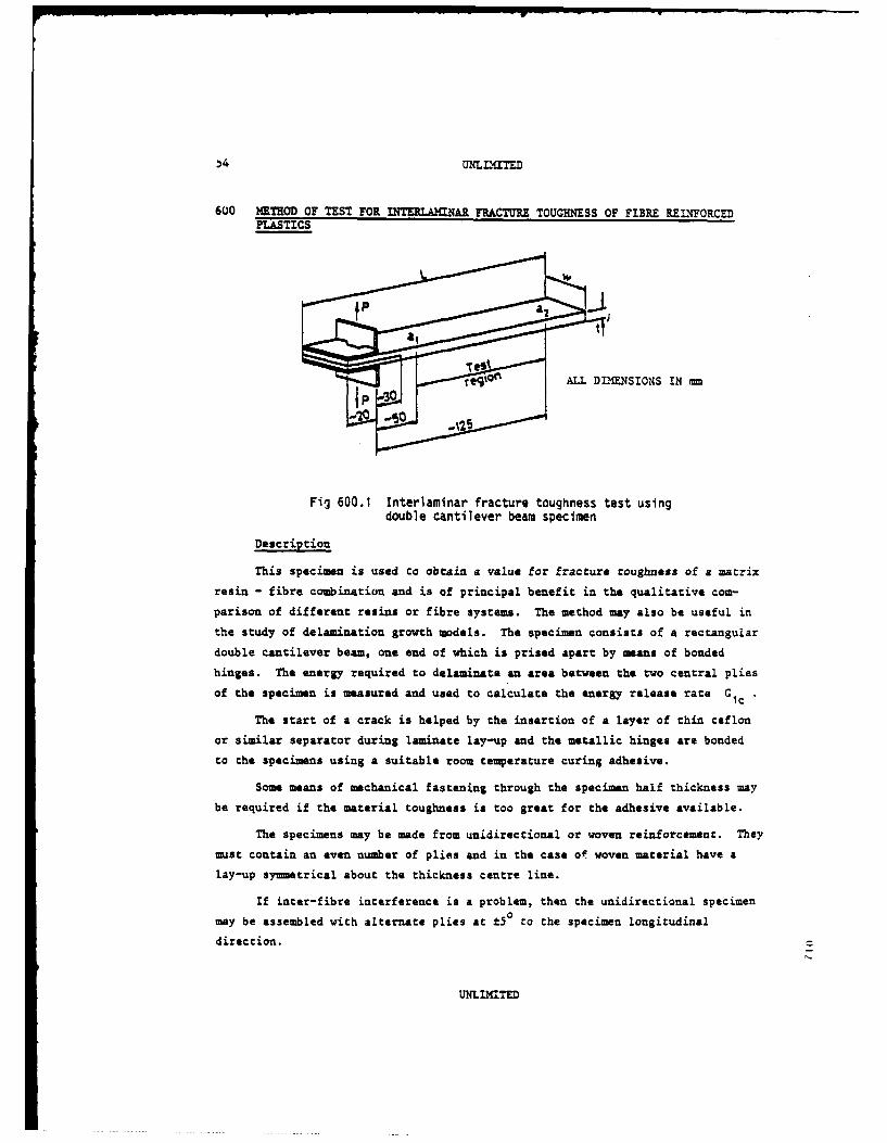
Fig 600.1 Interlaminar fracture toughness test using
double cantilever beam specimen
Description
This specimen is used to obtain a value for fracture toughness of a matrix
resin - fibre combination and is of principal benefit in the qualitative com-
parison of different resins or fibre systems. The method may also be useful in
the study of delamination growth models. The specimen consists of a rectangular
double cantilever beam, one end of which is prised apart by means of bonded
hinges. The energy required to delaminate an area between the two central plies
of the specimen is measured and used to calculate the energy release rate G1c
The start of a crack is helped by the insertion of a layer of thin teflon
or similar separator during laminate lay-up and the metallic hinges are bonded
to the specimens using a suitable room temperature curing adhesive.
Some means of mechanical fastening through the specimen half thickness may
be required if the material toughness is too great for the adhesive available.
The specimens may be made from unidirectional or woven reinforcement. They
must contain an even number of plies and in the case of woven material have alay-up symmetrical about the thickness centre line.
If inter-fibre interference is a problem, then the unidirectional specimen
may be assembled with alternate plies at t50 to the specimen longitudinal
direction.
UNLIMITED
UNhLLXITED 5
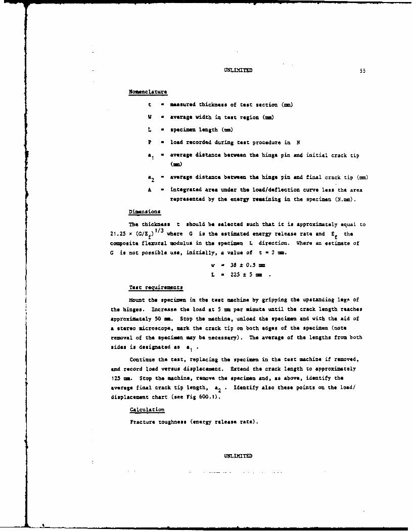
Nomenclature
t - measured thickness of test section (m)
W a average width in test region (m)
L - specimen length (m)
P - load recorded during test procedure in N
a1 a average distance between the hinge pin and initial crack tip
(Me)
a 2 = average distance between the hinge pin and final crack tip (mm)
A - integrated area under the load/deflection curve less the area
represented by the energy remaining in the specime (N. m).
Dimensions
The thickness t should be selected such that it is approximately equal to
21.25 x (WlEf)1/3 where G is the estimated energy release rate and Ef the
composite flexural modulus in the specimen L direction. Where an estimate of
G is not possible use, initially, a value of t - 3 m.
v - 38 t0.5 mm
L - 225 1:5m
Test requirements
Mount the specimen in the test machine by gripping the upstanding leg s of
the hinges. Increase the load at 5 m per minute until the crack length reaches
approximately 50 a. Stop the machine, unload the specimen and with the aid of
a stereo microscope, mark the crack tip on both edges of the specimen (note
removal of the specimen may be necessary). The average of the lengths from both
sides is designated as a •
Continue the test, replacing the specimen in the test machine if removed,
and record load versus displacement. Extend the crack length to approximately
125 mm. Stop the machine, remove the specimen and, as above, identify the
average final crack tip length, a2 . Identify also these points on the load/
displacement chart (see Fig 600.1).
Calculation
Fracture toughness (energy release rate).
UNLIMITED
I

56 UNLNaT
G. is given by
Gi ;-3A a 10 3 T, 2
~A
Displacement mm
ri vertical travelLa2
Fig 600.1 Report fracture toughness, fibre volume fraction
Validity
For valid comparisons, resin should be tested with identical fibres or
fabrics at identical fibre volume fractions.
Similarly different fibres or fabrics should be compared with the same
matrix resin.
UNLDITED

UNLIMITED 5
700 KTEoD OF TEST FOR BEARIG PROPERTIES OF MULTIDIRECTIONAL FIBRE REINFORCEDPLASTICS
Description
This specimen is used to determine the bearing strength of multidirectional
laminates and to measure the bearing stress versus hole deformation. It may be
made from undirectional tape, woven material or mixtures thereof, provided that
the laminate is axially orthotropic to obviate induced bending.
The specimen may be used for tension or compression tests: with many lami-
nates different strength values will be obtained.
The specimen is shown in Fig 700.1.
Nomenclature
t a thickness of specimen
d a hole diameter
w a width of specimen
L - length of specimen
e - distance from centre of hole to the free end of the
specimen
P . applied load (tension or compression)
PF a applied load at failure
a = measured deformation over gauge length
abult ' bearing stress at failure.
Dimensions
Values for w and a for various hole diameters are given in the following
table.
d v e
<4 30 24>4-5 35 30>5-6 40 36>6-7 45 42>7-8 50 48>8-9 55 54>9-10 60 60 t - between d/3 and d>10 6d 6d L a to suit test fixture.
UNLIMITED
II

8Ui I _
Tolerances
The hole must be on the centre line of the specimen to within ±0.1 mm. The
hole tolerances should conform to BS 4500 RIo (metric) or BS 1916 HI0 (imperial).
The specimen must be flat to within :0.05 ma.
Permitted deviations
For small holes (4 ma) w may be reduced to between 20 =- and 30 mm pro-
vided that w is not less than lot and 7d.
For specific purposes values of t outside the recommended range may be
used. However with lower values the average bearing stress at failure may be
affected by plate instability, whilst with higher values the average bearing
stress at failure may be affected by bolt bending.
Test requirements
The bolt through the specimen should be torque tightened to provide a level
of lateral constraint appropriate to the practical application to which the test
relates. A low constraint will permit a local 'brooming' failure, giving a
brushlike appearance around the loaded half of the hole. With higher levels of
constraint 'brooming' is prevented giving an increase in the ultimate bearing
stress.
For tension tests, a suitable test fixutre is illustrated in Fig 700.2.
For compression tests the same fixture may be used with compression jaws
in the test machine, or alternatively between platens with accurately parallel
end blocks.
The specimen must be carefully aligned in the test fixture and machine to
ensure axial loading.
When load versus hole deformation measurements are required a suitable
extensometer must be fitted to record the movement between the free end of the
specimen and bearing bolt in the test fixture.
The load should be increased uniformly to cause failure within 30-90 seconds.
Calculations
The ultimate bearing stress is calculated from the formula:
Pabolt dt
UNLIMITED

Bearing stress versus hole deformation data should be given in the form of
bearing stress versus Z elongation of the hole, is
P dP- versus - 100
Accurately measured values of d and t must be used.
Report bearing stress at failure, bearing stress versus Z elongation,
nominal fibre volume fraction, nominal and actual moulded thickness, bolt dia-
mter, bolt material, level of torque tightening, and any other significant
features, eg if transverse restraints are used.
Validity
To be valid bearing data, all damage must lie within the boundaries of the
specimen. Shear out or total failure of the specimen Ao not constitute valid
results.
Note that in specimens with large percentages of 00 fibres, splitting
parallel with the fibres can lead to premature shear out failure. This can be
prevented by applying transverse restraint to the specimen by means of edge
supports. In so doing however the validity of the test in relation to the
application it represents must be considered.
Bearing hole dia drmm (see under 'Tolerances')
0" axis
e L
Fig 700.1 Test specimen
UNLLMITED

60 UNLL'TED
X
Spacer plate
Mar dened stoelside plates
Mardefled steel bushes,sliding fit in sideI Plates
C -
/"-,. ' "-'-[ p]
' ;-/ 2.2d diameterraised boss
Bearing bolt
L.. Test specimen
Section X-X
Fig 700.2 Test fixture
UNLIMITED
UNLIMITED 6
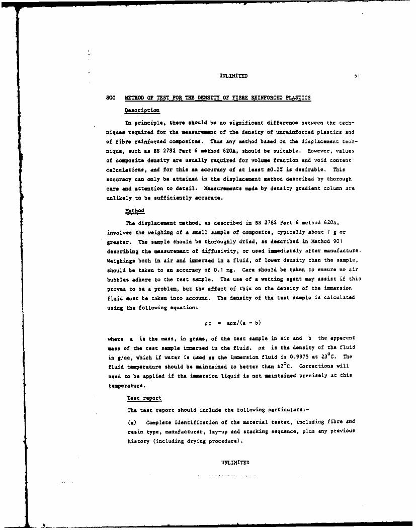
800 METROD OF TEST FOR THE DENSITY OF FIBE REINFORCED PLASTICS
Description
In principle, there should be no significant difference between the tech-
niques required for the measurement of the density of unreinforced plastics and
of fibre reinforced couposites. Thus any method based on the displacement tech-
nique, such as BS 2782 Part 6 method 620A, should be suitable. However, values
of composite density are usually required for volume fraction and void content
calculations, and for this an accuracy of at least *0.2% is desirable. This
accuracy can only be attained in the displacement method described by thorough
care and attention to detail. Masurements made by density gradient colum are
unlikely to be sufficiently accurate.
Method
The displacement method, as described in BS 2782 Part 6 method 620A,
involves the weighing of a small sample of composite, typically about I g or
greater. The sample should be thoroughly dried, as described in Miethod 901
describing the measurement of diffusivity, or used immediately after manufacture.
Weighings both in air and imersed in a fluid, of lower density than the sample,
should be taken to an accuracy of 0.1 mg. Care should be taken to ensure no air
bubbles adhere to the test sample. The use of a vetting agent may assist if this
proves to be a problem, but the effect of this on the density of the immersion
fluid must be taken into account. The density of the test sample is calculated
using the following equation:
at - aox/(a - b)
where a is the mass, in grams, of the test sample in air and b the apparent
mass of the test sample immersed in the fluid. px is the density of the fluid
in g/cc, which if water is used as the immersion fluid is 0.9975 at 230C. The
fluid temperature should be maintained to better than ±20C. Corrections will
need to be applied if the imersion liquid is not maintained precisely at this
temperature.
Test report
The test report should include the following particulars:-
(a) Complete identification of the material tested, including fibre and
resin type, manufacturer, lay-up and stacking sequence, plus any previous
history (including drying procedure).
UNLIMITED

62 LL' I TE
(b) Sample dimeusions.
(c) Reference to the mechod employed (eg BS 2782, Method 620A).
(d) Density as calculated from the above equation, together with the test
temperature and details of the immersion fluid.
UNLIMTED
_ 9_.L = _ i - ,,. . . ,.- ==, ~ m ,,

UNnLIMTE 63
801 IETEOD OF TEST FOR TE DETERMNATION OF THE COEFFICIENT OF LLNEAR THER.LEXANSION OF FUS RINFRCOD PLASTICS
Description
This Data Sheet defines the recoimnded method for measuring the coefficient
of linear thermal expansion. The method is based upon ASTM D696-79 and E228-79.
The method may be applied to unidirectional, multidirectional and woven
laminates. However, because of the directional influence of the reinforcmant,
their interaction with each other and the matrix, it is necessary to ensure
sufficient specimens are evaluated to accurately determine the property in the
specified direction of the material or laminate.
The coefficient of linear thermal expansion is determined by use of a
dilatometer having the critical expansion components constructed from vitreous
silica. The principle is that the specimen is placed at the bottom of the outer
tube with the inner tube resting on it. Variation in the length of the specimens,
due to temperature changes, are measured by the differences occurring between the
inner and outer tubes (Fig 801.1). The temperature changes are brought about by
immersing the dilatomater in a liquid bath accurately controlled at the desired
temperature.
At the test conditions the materials shall have negligible creep or elastic
strain rate.
The expansion of the specimen is influenced by moisture content; to elim-
inate this phenomenon the specimen must be pre-dried to a constant weight, see
Method 901. Expansion is also affected by stress relaxation, transitional and
phase changes; these effects can be reduced by pre-conditioning of the specimens
and selection of a suitable range of test temperatures.
The ends of the specimens shall be flat and perpendicular to the length
axis, and may be protected against indentation by thin steel shims (0.012 to
0.020 inch thick) bonded with adhesive suitable for the test environment.
Details of the specimen geometry are given in Fig 801.2.
Nomenclature
Lo - length of specimen at room temperature
LI - length of specimen at T1
L2 = length of specimen at T2
Ti - Lower temperature of assessment
UNLIMITED

64 UNIfITED
T2 a higher temperature of assessment
a - coefficient of linear thermal expansion per degree Celsius
AL - change in length of specimen due to beating or cooling
AT - temperature difference over which change in length was
measured.
Test requirements
Specimens mast be carefully aligned in the dilatometer to prevent friction.
The temperature stability of the specimns is indicated by a nil movement of the
measuring device over a period of 5-10 minutes at the test temperature. The top
of the specimen oust be at least 50 m below the level of the bath.
The open end of the dilatometer shall be at least 50 um above the liquid
level.
Calculations
The coefficient of linear thermal expansion is given by
4LLoAT
Report
The form and dimensions of the test specimens, the type of apparatus,
temperatures between which - was determined and average a per degree Celsius
should be reported.
C
UNLIMITED
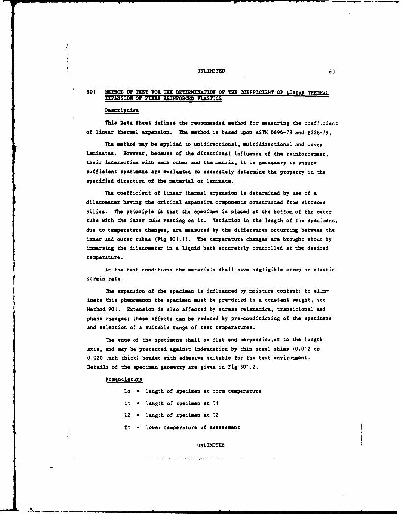
UNLD T D 63
801 "MMTD OF TEST FOR TE DETEMCU:nON OF THE COEFFCI T OF LZIEAR TH ,LTIZPANSION OF FIBRE REIFORC D PLASTICS
Description
This Data Sheet defines the recomended method for measuring the coefficient
of linear thermal expansion. The method is based upon ASTM D696-79 and E228-79.
The method may be applied to unidirectional, multidirectional and woven
laminates. However, because of the directional influence of the reinforcement,
their interaction with each other and the matrix, it is necessary to ensure
sufficient specimens are evaluated to accurately determine the property in the
specified direction of the material or laminate.
The coefficient of linear thermal expansion is determined by use of a
dilatometer having the critical expansion components constructed from vitreous
silica. The principle is that the specimen is placed at the bottom of the outer
tube with the inner tube resting on it. Variation in the length of the specimens,
due to temperature changes, are measured by the differences occurring between the
inner and outer tubes (Fig 801.1). The temperature changes are brought about by
inersing the dilatometer in a liquid bath accurately controlled at the desired
temperature.
At the test conditions the materials shall have aegligible creep or elastic
strain rate.
The expansion of the specimen is influenced by moisture content; to elim-
inate this phenomenon the specimen must be pre-dried to a constant weight, see
Method 901. Expansion is also affected by stress relaxation, transitional and
phase changes; these effects can be reduced by pre-conditioning of the specimens
and selection of a suitable range of test temperatures.
The ends of the specimens shall be flat and perpendicular to the length
axis, and may be protected against indentation by thin steel shims (0.012 to
0.020 inch thick) bonded with adhesive suitable for the test environment.
Details of the specimen geometry are given in Fig 801.2.
Nomenclature
Lo - length of specimen at room temperature
LI - length of specimen at TI
L2 a length of specimen at T2
T1 - lower temperature of assessment
UNLIMITED
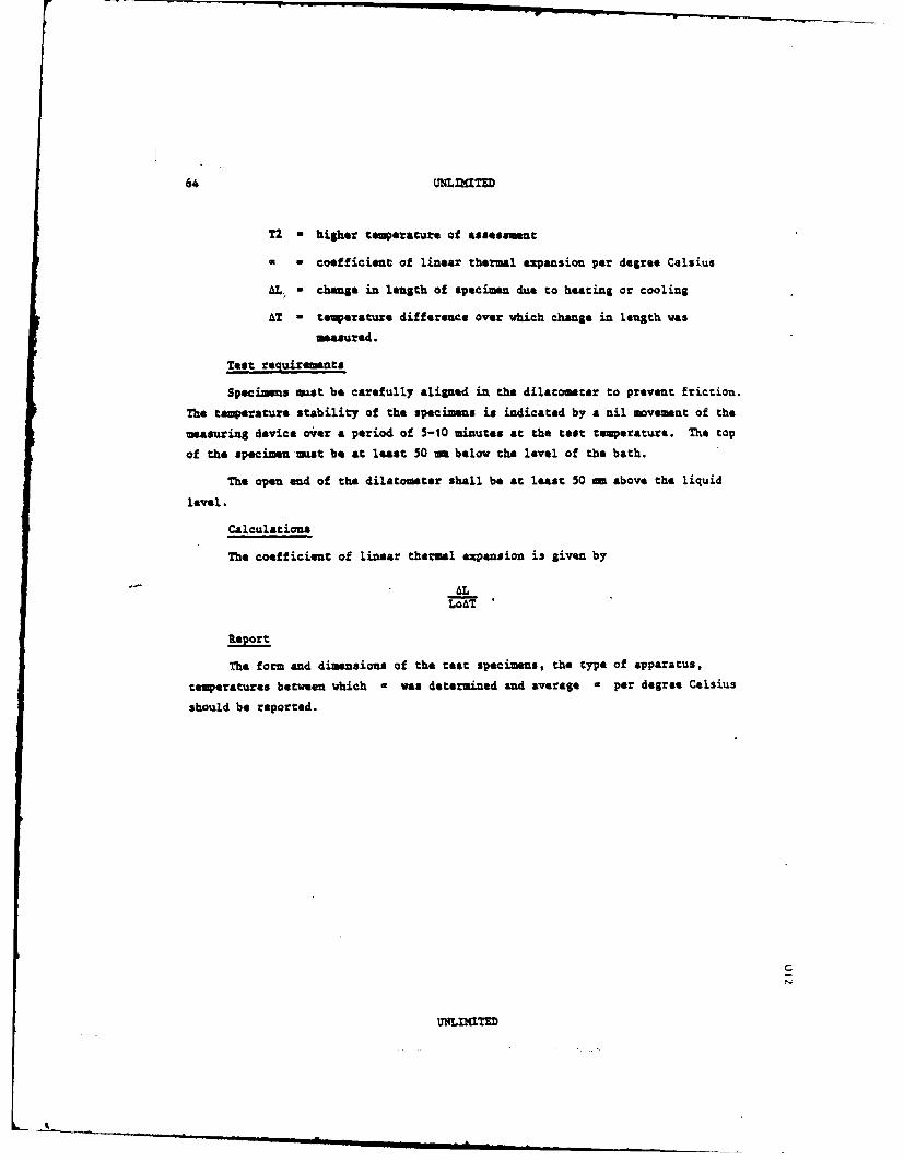
64 UNLaTE
T2 - higher temperature of assessment
a | coefficient of linear thermal expansion per degree Celsius
4L. - change in length of specimen due to heating or cooling
AT - temperature difference over which change in length was
measured.
Test requirements
Specimens must be carefully aligned in the dilatometer to prevent friction.
The temperature stability of the specimens is indicated by a nil movement of the
measuring device over a period of 5-10 minutes at the test temperature. The top
of the specimen must be at least 50 mm below the level of the bath.
The open end of the dilatometer shall be at least 50 mm above the liquid
level.
Calculations
The coefficient of linear thermal expansion is given by
AL
Report
The form and dimensions of the test specimens, the type of apparatus,
temperatures between which * was determined and average a per degree Celsius
should be reported.
iC
I I I __ m mm mLIMITED

UnLMTED (65
=mT ioR soWon GuvGE
- M1TniG 3LOCIC
-vIMUS SILICA ROD
SLnmG PIT
TM0COPT
inPLM WIT QGWM ?TAT
0 1 112, 5 1Fig 801.1 oilatometer, tube type
uI4LIaT

66 UNLD4TED
- ,3.0 1 0.2
/. 50.0 . ..I125.0 'wX
12.0 1 0.5
ALL DI4S ONS TN M,
Fig 801.2 Specimen configuration
UNLIMTED
UNLL41TED 67
802 HIMROD OF TEST FOR THE OUTGASSING OF FIBRE REINFORCED PLASTICS
1 scope
The test method covers a screening technique to determine the volatile con-
tent of materials exposed to a vacuum environment at elevated temperature. Three
parameters are measured: total mass loss (TM), collected volatile condensable
materials (CVCI), and the recovered mass 1oi (ML). The method describes the
test apparatus and related operating procedures for evaluating the mass loss of
materials being subjected to 1250 C at less than 7 x 10"3 Pa (5 x 10- 5 torr) for
24 hours. The overall mass loss can be classified into condensables and non-
condensables. The former are characterized herein as being capable of condensing
on a collector at a temperature of 25C.
This procedure is intended for the testing of composite materials for use
in a space environment. The method is primarily a screening technique for
materials and is not necessarily valid for computing actual contamination on a
system or component because of differences in configuration, temperatures, and
material processing. The criteria used for the acceptance and rejection of
materials shall be determined by the user and based upon specific component and
system requirements.
2 Definitions
Collected volatile condensable material, CVCM, is the quantity of outgassed
matter from a test specimen that condenses on a collector maintained at a specific
constant temperature for a specified time. CVCM is expressed as a percentage of
the initial specimen mass and is calculated from the condensate mass determined
from the difference in mass of the collector plate before and after the test.
Total mass loss, TML, is total mass of material outgassed from a specimen
that is maintained at a specified constant temperature and operating pressure
for a specified time. TML is calculated from the mass of the specimen as measured
after pre-conditioning and immediately after completion of the test and is
expressed as a percentage of the initial specimen mass.
Recovered mass loss, RML, is the mass loss measured after the specimen has
been dried in accordance with procedures laid down in Method 901 of this document
and allowed to pre-condition at 200 C and 65Z relative humidity for 24 hours
following the testing. This RML is determined after THL has been measured. RML
is calculated from the mass of specimen as measured after pro-conditioning of the
UNLfIITED

68 'L LITED
test and after post-conditioning following casting expressed as a percentage of
the initial specimen mess.
3 Sumary of method
The dried test specimen is pre-conditioned to 20 0 C and 65Z relative humidity
for 24 hours in a preformed, degreased container (boat) that has been weighed.
After this exposure, the boat and specimen are weighed and put in one of the
specimen compartments in a copper heating-ring that is part of the test apparatus.
The copper heating-ring can accommnodate a number of specimens for simultaneous
tasting. The vacuum chamber in which the heating-ring and other parts of the
test apparatus are placed is then sealed and evacuated to a vacuum of at least
7 x 10- 3 Pa (5 X 10"5 tort). The heating-ring is used to raise the specimen
compartment temperature to 125 0 C. This causes vapour from the heated specimen
to stream from the hole in the specimen compartment. The vapour passes into a
collector chamber in which some vapour condenses on a previously-weighed and
independently temperature-controlled, chromium-plated collector plate that is
maintained at 250 C. Each specimen compartment has a corresponding collector
chamber that is isolated from the others by a compartmented separator plate to
prevent cross-contamination. After 24 hours, the test apparatus is cooled and
the vacuum chamber is repressurized with a dry, inert gas. The specimen and the
collector plates are weighed. From these results and the specimen mass deter-
mined prior to the vacuum exposure, the percentage TML and percentage CVC( are
obtained. Normally, the reported values are an average of the percentages
obtained from three samples of the same material.
NOTE: It is also possible to conduct infra-red and other analytical tests
on the condensates in conjunction with mass-loss tests. Infra-red trans-
parent flats may be used for infra-red analysis. These flats are nominally
25 me ( inch) in diameter by 3.2 mm (0.125 inch) thick, and are supported
edgewise in a metal holder that fits into the collector plate receptable.
On completion of the test, the flats are placed into an infra-red salt flat
holder for examination by an infra-red spectrophotometer. As an alternative
method, the condensate may be dissolved from the metallic collector, the
solvent evaporated, and the residue deposited on a salt flat for infra-red
tests. Infra-red transparent flats shall not be used for CVCH
determinations.
After the specimen has been weighed to determine the THL, the RM1L can be
determined, as follows. Post-condition the specimen for 24 hours at 200C C
UNLLITED
A._

UNLfL TED 69
and 65Z relative humidity to permit sorption of water vapour. The specimen mass
after this exposure is determined. From these results and the specimen mass
prior to vacuum exposure, the percentage LSL is obtained.
Three empty specimen chambers and collector plates in the heater-ring shall
be used as controls to ensure chat adequate cleaning procedures have been
followed after each test.
A typical test apparatus can have as many as 24 specimen chambers with 24
associated collector plates so that a number of specimens of different types can
be tested each time the foregoing operations are conducted. Three specimen com-
partments shall serve as controls and three can be used for each type of material
being tested. The equipment shall be calibrated at least once a year by using
previously tested materials as test specimens or by round-robin tests between
facilities.
The equipment shall be considered acceptable if the results meet the
following criteria:
CVCM/Tl/RNL > 0.21 within t20% (relative) of 'standard' value
CVCO/TMUL/R1L < 0.21 within tO.05 (absolute) of 'standard' value
The apparatus may be oriented in any direction as long as the configuration
shown in Fig 802.1 is maintained and bulk material does not fall from the sample
holder nor obstruct the gas exit hole. The dimensions for critical components
given in Fig 802.1 and Table 802.t are provided so that apparatus constructed
for the purpose of this test may provide uniform and comparable results.
4 Significance and use
This test method evaluates, under carefully controlled conditions, the
changes in the mass of a test specimen on exposure under vacuum to a temperature
of 125 0 C and the mass of those products that leave the specimen and condense on
a collector at a temperature of 25 0 C. Comparisons of material outgassing proper-
ties are valid at 125 0 C only. Samples tested at other temperatures may be com-
pared only with other materials which were tested at that same temperature.
The measurements of the collected volatile condensable material are also
comparable and valid only for similar collector geometry and surfaces at 250 C.
The simulation of the vacuum of space in this test method does not require that
the pressure be as low as that encountered in interplanetary flight (for example,
UNLIMITED
J_"mnknn n N

70 UNLna=
10- 1 2 Pa (10" 14 tor)). It is sufficient that the pressure be low enough thac
the mean free path of gas molecules be long in comparison to chamber dimensions.
This method of screening materials is considered a conservative one. It is
possible that a few materials will have acceptable properties at the intended use
temperature but will be eliminated because their properties are not satisfactory
at the test temperature of 125°C. Also, materials that condense only below 250C
are not detected. The user may designate additional tests to qualify materials
for a specific application.
5 Apparatus
The apparatus used in the determination of TML and CVCM typically contains
two resistance-heated copper rings. The lower ring contains 24 specimen chambers,
the upper ring 24 holes. The open section of the upper ring allows vapours from
the specimen to pass through a hole into a collector chamber where it impinges
on a removable chromium-plated collector plate maintained at 25 0 C throughout the
test, (see Pigs 801.1 and 801.2). Variations in test apparatus configurations
are acceptable if critical dimensions are maintained as prescribed in Table 801.1.
The operation of the vacuum chamber system and any device for raising the
vacuum bell can be automatically controlled. Power to the heating element
mounted in the copper rings is generally controlled by variable transformers
through temperature controllers. Recorders with an electronic icepoint reference
junction feedback may be used to monitor the heater ring temperatures. A heat
exchanger using a suitable fluid may be used to maintain the collector plate at
250 C during the test.
It is recommended that the vacuum chamber system include automatic controls
to prevent damage in the event of power failure when in unattended operation.
Care must be taken to prevent backstreaming of oil from vacuum or diffusion pumps
into the vacuum chamber.
6 Test specimens
Test specimens shall be protected from contamination by packaging them in
clean new polyethylene bags after preparation and for transportation to the test
facility.
Test specimens shall be supplied preferably as 1.5 to 2.Om thick laminates.
Thicker specimens may be submitted but must be cut dry, into 1.5 to 2.0nm thick
sheets. The sheets must be cut dry to the final size of material for testing
which shall be cubes of 1.5 to 2.0 ma side. Minimum specimen masses in the
UNLIMITED
S I

UNLI(TED 71
order of 200 mg are required. If smiller quantities are utilized, the accuracy
of the measurements may be impaired.
It is absolutely essential that specimen materials not be contaminated at
any step in the specimen fabrication process. Most importancly, specimen material
shall not be handled with the bare hands as oils from human skin are volatile and
condensable and thus will cause false TnM and CVCM results.
To control contamination, suitable gloves or finger cots shall be worn
during all specimen preparation steps. All materials will be tested in the 'as-
received' condition, unless a cleaning schedule is advised.
Only the use of cleaning solvents that are known to be non-reactive with
the specimen material and that leave no residue are permitted.
7 Procedure
7.1 Weigh a prepared nickel boat (Mt).
7.2 Add the test specimen (100-300 ng) to the boat and pre-condition the
sample at 65% relative humidity and 200 C for 24 hours.
7.3 Weigh the pre-conditioned specimen and boat (1 o ) ,
sample weight a (Mo - Id)
7.4 Weigh a prepared collector and mount it into its cooling-plate
receptacle ( ).
7.5 Place the specimen and boat into a specimen compartment of the
heating-ring in the microvolatile condensable system.
NOTE: Prior to the operation noted in procedure 7.5, the copper compartment
ring, separator, and cooling plate shall be clean, in position, and awaiting
the specimen boats and collector-plates.
7.6 Close the vacuum system and evacuate it to 7 x 10⁻³ Pa (5 x 10"5 torr)
or less within 1 hour.
7.7 Control of the collector-plate temperature at 250 C shall be achieved
within the first hour of pump-down.
7.8 When a pressure of 7 x 10"3 Pa (5 x 10- 5 torr) is reached, turn on
the heater-ring and adjust the variable transformers to raise the heater-
ring temperature to 125 0 C within 60 minutes.
7.9 Maintain the collector-plate temperature at 25 0 C.
UNLIMITED
- . -
72 UNLIMITED
7.10 Maintain the heater-ring temperature at 125 0C for 24 hours, then
close the high vacuum valve to the pumping system and turn off the heater-
ring.
7.11 Open the vent valve and backfill with white spot nitrogen regulated
within a gauge pressure range from 10-30 kPa (2-4 psi) above atmosphere
to cool the rings rapidly.
7.12 Allow the heater-ring to cool sufficiently to permit handling
(nominally 2 hours to reach 50 0 C). Then turn off the collector-plate heat
exchangers, return the vacuum chamber to room pressure using the clean,
dry nitrogen, and open the chamber.
7.13 Store nickel boats with specimens and respective collector-plates in
desiccators (using silica gel desiccant) imediately. After specimens have
cooled to approximately room temperature, but no longer than half-hour,
remove and weigh each specimen within 2 minutes of its removal from the
desiccators (Hf ). Weigh the collectors (X p'). Control collector-plates
are used to detect cross-contamination or poor technique. The mass change
of all the sample collector-plates must be corrected by subtracting or
adding the average mass change of the three blanks before calculating the
CVCM (Mb). A change in mass greater than t 30 ug of any one of the blank
collectors shall be cause for rejection of the whole run. The system must
be thoroughly cleaned and out-baked prior to future use. All data acquired
during runs when this occurs shall be discarded or retained with a note
indicating the discrepancy.
7.14 Post-condition the foregoing samples at a relative humidity of 65%
at 20 0 C for 24 hours to determine the RML. Re-weigh the post-conditioned
specimens and boat (h,).
8 Calculation of results
Three results are calculated:
(i) Total mass loss (THL).
(ii) Recovered mass loss (RNL).
(iii) Collected volatile condensible material (C'VCM).
The equations for these are:
(i) (m0 - mf X 100
mIm
UNLIMITED

UNLLXTED 73
(M° -n,) x tOOZ
(iii) (mP O * Mb X 1002
mM
where mo specimen + boat mass after pro-conditioning
af mass of specimen + boat after test
a a ss of sample (M - M)
MR mass of specimen + boat after 2' hours post-conditioning
m mass of collector before testP
mp' a mass of collector after test
a mass of sample boat
mb average mass change of three blank collectors.
9 Report
The report shall contain the following information:
(i) Trade name and number of the material, the manufacturer, the batch
or lot number, or other such identification.
(ii) Sumary of the preparation schedule (cure time and temperature,
post-cure, cleaning procedures), date prepared.
(iii) Percentage of total mass loss, nL (the average value).
(iv) Percentage of recovered mass loss RML (the average value).
(v) Percentage of collected volatile condensable material, CVCM (the
average value).
(vi) Infra-red spectrum or other analytical description of the condensed
cont-intion when determined.
(vii) Remarks about any noticeable incident or deviation from standard
conditions observed during the test.
10 Tolerances
The following tolerances shall apply:
All temperatures shall be 1 0 C (unless otherwise stated).
Relative humidity t5Z.
Weighings tI Ug.
UNLIMITED

74 UNLLfITED
11 General cleanliness and handling of samples
The weight changes being measured are extremely small, so it is imperacive
that samples are handled correctly to eliminate contamination and erroneous
results.
General
(1) When handling parts of the apparatus within the vacuum chamber,
clean nylon gloves must be worn.
(ii) Sample boats must only be handled with clean forceps or clean
nylon gloves.
(iii) Collectors must only be handled using a suitable metallic handling
device.
(iv) When preparing samples, clean nylon gloves must be worn.
Apparatus preparation
Sample boats
(i) Clean ultrasonically in a chloroform: acetone (50:50) mixture for
30 minutes.
(ii) Bake overnight in a vacuum oven at 165 0 C nominal and <50 ubar.
(iii) Store in a clean container, open to the atmosphere, at 65% relative
humidity and 200 C.
Collectors
The procedure is similar to that described above, except that the
collectors are stored for 24 hours in a desiccator after removal from the
oven. When not in use the collectors shall be stored in a desiccator.
Apparatus
Both parts of the cooled ring should be swabbed with copious amounts
.of chloroform: acetone mixture, to remove condensed volatiles. Use a lint
free cloth or white tissue.
The base plate around ports and ring supports should be swabbed to
remove any dust.
Bake out of system
Prior to every run the system shall be baked out by heating the rings
to a nominal 1650 reducing the pressure to approximately 10"3 tort for a
period of 16 hours.
UNLIMITED
S.

UNLnaTED 75
Table 802.1
Test apparatus dimensions(see Fig 802.1)
Letter M Tolerance Notes
AA 6.3 *0.1 diameterB
BA 11.1 *0.1 diaeterB
CA 33.0 :t0.1 diameterB
DA'C 13.45 *0.10
EAC 9.65 :t:0.10
FA -C 0.65 *0.10
G 7.1 *0.3
RA 0.75 t0.10 stock size
JA 12.7 *-0.3
K 9.6 *0.8
M 16.0 :0.1
For a system where compartments are arranged ona ring each individual chamber shall be at50 * 0.8ma centres and there shall be 24 com-partments on each ring.
A Critical dimensions that must be maintainedfor test results to be comparable.
B Diameters must be concentric to *0.1 m for
test results to be comparable.
C Dimensions include plating thickness.Satisfactory surfaces have been produced bymaking substrate surface finish 1.6 m RMShighly polished, plated with electrolesenickel, 0.0127 mm thick, and fini3hed withelectroplated chromium, 0.0051 mm thick.
UNLfITED
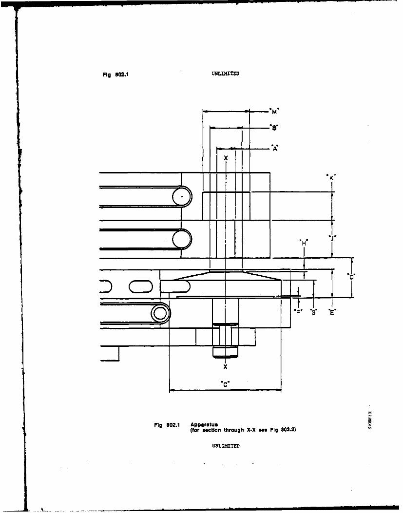
Fig 802.1 UNUL f ED
m
V T
YETx
Fig 802.1 Apparatus(for section through X-X "a Fig 802.2)
UNLIMITED
ImI ID

JMIT " Pig 802.2
Cooling plateCollector chanber
/f Collector plate
, \. ~Cover/ / plate
/ d ,Specimen\, compartment
//" Coppr heater bar
Separator plate
Fig 802.2 Schematic of critical portion of teat apparatus(section X-X of Fig 802.1)
UNLIMTED

78 UNLIMITED
900 BACKGROUND INFORMATION ON ENVIRONMENTAL EFFECTS
I Introduction
This sheet provides supplementary background information on environmental
effects and is intended to be read in conjunction with the data sheets giving
recommaendations for the monitoring of moisture contentI and for the conditioning2
of test specimens 2
2 Effect of volume fraction
Except for the case of some polymer fibres, eq Aramid (see section 4) only
the resin matrix absorbs moisture. Hence, M , expressed as a percentage of the
composite weight, will decrease with increasing fibre volume fraction Vf
Exaple 2.1
if at 60% Vf a composite contains 1.1% of water what is the expected
water content at 70% Vf?
The following densities are assumed:
resin 1.3 gm/cc
fibre 1.8 gm/cc.
Assume a dry volume of 100 cc. With 60% Vf this gives 60 cc fibre and
40 cc resin. With the above densities this gives 108 gm, fibre and 52 gm
resin, total 160 gm. For 1.5% moisture this gives 1.76 gm of absorbed
moisture. Hence, as all moisture is held in the resin,
1.76Resin moisture content - 1.76 x 100 - 3.385%
With the same dry volume and material densities, but 70% Vf we have 126 gm
fibre 39 gm resin and a total dry weight of 165 gm. Resin moisture content
as a percentage will, however, be unchanged, hence
Moisture content u 39 x 0.03385 - 1.32 gm
and 1.32Composite moisture content * = 0.8%
3 Effect of voids
Generally, the material will be rejected if the void content Vv is
significant and the value of 2% used in this example must be considered as high.
A distinction is made between 'external' voids where moisture can enter without
UNLLIITED

UNLnCTED 79
passing through any part of the resin matrix and 'internal' voids where at least
some diffusion through the resin must take place.
In the case of internal voids the effect of the moisture within the void
on the measurement of moisture uptake would appear to be small. Following Ref 3,
we can expect for initially dry material that the relative humidity within the
void will rise to eventually reach the conditioning humidity. Even at 100% RH
figoesf given in Ref 4 show that, at 60eC. the mass of the moisture in the voidsfor 2Z V vis only about 2 x 10⁻⁷ of the specimn mass. The problem here, which
is considered in Raf 3, is the affect of a rise in temperature.
For external voids the extreme case to be considered is when these voids
are filled with water. Clearly, it is not possible to remove this prior to
weighing. The following exple considers such a case, with Vv - 2%, and all
voids of the external type filled with water.
Example 3.1If a 60% Vf composite with a void content Vv of 2%, all of the external
type and full of water, contains 3% of moisture, at saturation, what is
the expected saturated moisture content of a void free laminate of the
same Vf ?
Assuming a dry volume of 100 cc, this gives 58.8 cc fibre, 39.2 cc resin
and 2 cc void. With the same densities as in the example of section 2.8,
this gives a total weight of 156.8 gm, with 50.96 gn of resin. The total
moisture content is therefore 4.704 gm, 2 gm in the voids and 2.704 gm in
the resin, hence
2.704Resin moisture content - 5096 x 100 - 5.306Z
For a dry void free volume of 100 cc with 60% Vf, we have 60 cc fibre and
40 cc resin, giving 108 gm fibre and 52 gm resin, a total dry weight of
160 gin. Resin moisture content as a percentage will however be unchanged,
hence,
Moisture content 52 x 0.05306 a 2.759 gmSand 2.759
Composite moisture content - 2. - 1.724%
UNLIMITED
IL. I I

80 ULI ITED
4 Moisture uptake of glass fibre and polymer fibre composites (eq aramid)
Although not quite as important with the new conditioning methods, it is
nevertheless useful to know how to estimate the expected moisture uptake of
one type of composite from data on another type. In this section this is done
for glass fibre and aramid composites using data obtained from CFC.
Example 4.1
Using the following data, what moisture level is expected in a glass fibre
composite at 70Z RE?
Density of resin - 1.3 gm/cc
Density of glass fibre - 2.55 gm/cc
Moisture level in resin at 70% RE - 3.434%
Volume fraction - 60Z.
Assume a dry volume of 100 cc. With 60% Vf this gives 60 cc fibre and
40 cc resin. With the above densities this gives 153 gm fibre and 52 gm
resin, total 205 gm. Hence, as glass fibre does not absorb moisture,
Mass of absorbed moisture - 52 x 0.03434 - 1.786 gm
1.786Hence moisture update of glass fibre composite - 1.786-- 0.87%
Example 4.2
Using the following data, what moisture level is expected in an aramid
fibre composite at 70Z RE?
Density of resin - 1.3 gm/cc
Density of aramid fibre - 1.45 gm/ct
Moisture level in resin at 70% REH - 3.409%
Moisture level in fibre at 70% RE - 3.0%
Volume fraction = 60%.
Again, assume a dry volume of 100 cc. With 60% V, and the above densities
this gives 87 gm fibre and 52 gm resin, total 139 gm resin. Aramid fibres
are moisture absorbent, hence
Mass of moisture absorbed into fibres - 87 x 0.03 e 2.61 gm
Mass of moisrure absorbed into resin - 52 x 0.03409 - 1.77 gm
Total absorbed moisture - 4.38 gm
UNLIMITED

UNLIMITED Si
• 4.38
Hence moisture uptake of aramid composite 4 .3 3.15Z
Comparative figures
Table 900.1 gives a comparison of expected moisture levels in carbon fibre,
glass fibre and aramid composites at three levels of humidity, 70Z, 85% and 952.Note that for the glass fibre composite the resin properties assumed are taken
from data for a 1250 cure system. For the carbon and aramid composites the
properties are taken from data for a 10nC cure system. Please note also the
remarks of section 6.
5 Loss of moisture during elevated temperature testing
As pointed out in Ref 2, testing at elevated temperature can involve
significant moisture loss. This applies particularly to fatigue testing where
extended elapsed times are generally the rule and to full scale structural or
large structural element tests where only fairly slow heat-up rates can be
achieved.
For coupon testing it has been comon practice to allow a 10 minute 'heat
soak' to take place at the test temperature prior to the commencement of loading.
The purpose of this soak is to eliminate distortion due to non-uniform tempera-
ture distributions.
It is clearly undesirable that this drying should take place as at least
partial recovery of property can be expected in the affected outer plies. For
large scale tests, including fatigue tests, it is strongly advised that moisture
levels be maintained during the loading sequence. This should be done by main-
taining the appropriate humidity level throughout and may require the construc-
tion of an ad hoc climate chamber round the test piece. If the test temperature
is in excess of 100 0C high humidity levels can be maintained only by raising the
boiling point by pressurisation ('super heated' steam )
Testing performed at Ae has shown that for 3-. thick FADD specimens the
heat soak time can be reduced to 2-3 minutes. This could be employed for most
coupon tests although for thicker specimens and possibly for different test rigs
somewhat longer soaks may be necessary. Subject to this proviso, it is
recommended that heat soak times be reduced to this lower level.
In order to illustrate the effect of drying during elevated temperature
some simple calculations have been performed. Taking 2m thick XAS/914C material
as an example, it has been assumed that conditioning was to moisture level of
UNLIMITED
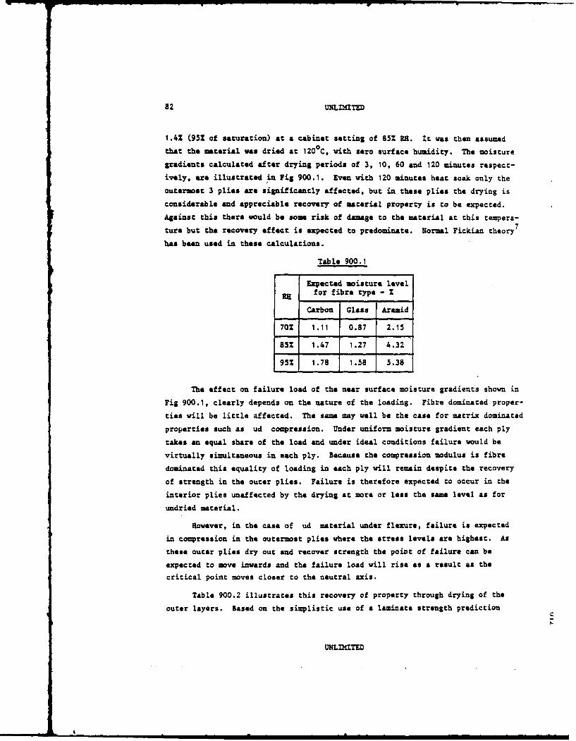
82 ULI ITE
1.4% (95% of saturation) at a cabinet setting of 85 RE. It was then assumed
that the material was dried at 1200C, with zero surface humidity. The moisture
gradients calculated after drying periods of 3, 10, 60 and 120 minutes respect-
ively, are illustrated in Fig 900.1. Even with 120 minutes heat soak only the
outermost 3 plies are significantly affected, but in these plies the drying is
considerable and appreciable recovery of material property is to be expected.
Against this there would be some risk of damage to the material at this tempera-
ture but the recovery effect is expected to predominate. Normal Fickian theory7
has been used in these calculations.
Table 900.1
Expected moisture levelfor fibre type - Z
Carbon Glass Aramid
70Z 1.11 0.87 2.15
85% 1.47 1.27 4.32
95% 1.78 1.58 5.38
The effect on failure load of the near surface moisture gradients shown in
Fig 900.1, clearly depends on the nature of the loading. Fibre dominated proper-
ties will be little affected. The same may well be the case for matrix dominated
properties such as ud compression. Under uniform moisture gradient each ply
takes an equal share of the load and under ideal conditions failure would be
virtually simultaneous in each ply. Because the compression modulus is fibre
dominated this equality of loading in each ply will remain despite the recovery
of strength in the outer plies. Failure is therefore expected to occur in the
interior plies unaffected by the drying at more or less the same level as for
undried material.
However, in the case of ud material under flexure, failure is expected
in compression in the outermost plies where the stress levels are highest. As
these outer plies dry out and recover strength the point of failure can be
expected to move inwards and the failure load will rise as a result as the
critical point moves closer to the neutral axis.
Table 900.2 illustrates this recovery of property through drying of the
outer layers. Based on the simplistic use of a laminate strength prediction
UNLIMITED
I
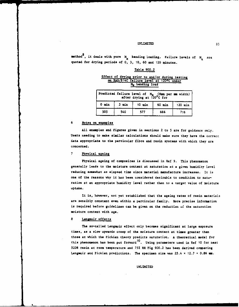
UNLLITED 83
mthod8 , it deals with pure M bending loading. Failure levels of M arex xquoted for drying periods of 0, 3, 10, 60 and 120 minutes.
Table 900.2
Effect of drying prior to and/or during testingon XAS/914C failure level an 120oC under
M.x banding load
Predicted failure level of Mx (N-m per = width)
after drying at 1200C for
0 min 3 min 10 min 60 min 120 min
505 540 577 666 716
6 Notes on examples
All examples and figures given in sections 2 to 5 are for guidance only.
Users needing to make similar calculations should make sure they have the correctdata appropriate to the particular fibre and resin systems with which they are
concerned.
7 Physical ageing
Physical ageing of composites is discussed in Ref 9. This phenomenongenerally leads to the moisture content at saturation at a given humidity level
reducing somewhat as elapsed time since material manufacture increases. It is
one of the reasons why it has been considered desirable to condition to satu-
ration at an appropriate humidity level rather than to a target value of moisture
uptake.
It is, however, not yet established that the ageing rates of resin materials
are sensibly constant even within a particular family. More precise information
is required before guidelines can be given on the reduction oi the saturation
moisture content with age.
8 Lansmuir effects
The so-called Langmuir effect only becomes significant at large exposure
times, as a slow upwards creep of the moisture content at times greater than
those at which the Fickian theory predicts saturation. A theoretical model for10this phenomenon has been put forward . Using parameters used in Ref 10 for neat
5208 resin at room temperature and 75% RH Fig 900.2 has been derived comparingLangmuir and Fickian predictions. The specimen size was 25.4 x 12.7 x 0.86 mm.
UNLIMITED
I

84 UNLnhaTED
From Fig 900.1 it Will be observed chat:
(a) The Langmuir and Fickian models differ significantly only at large
exposure times. (Note that 100 days exposure for 0.86 m thickness Sives
roughly the same moisture uptake as 546 days for 2 mm thickness).
(b) The Langmir and physical agein$ effects appear to be in opposition.
However, the Langair affect manifests itself during a continuing absorp-
tion process. Physical ageing appears to occur mainly during storage
dwells.
(c) The Langmuir effect appears to make more difficult the determination
of the equilibrium concentration.
9 Note on quick methods
The recommended conditioning method1 ,2 involves longer conditioning times
than previous techniques where material was soaked to a target value of moisture
content using a high humidity. Consequently, and in particular where thicker
material is involved the pressure to resort to 'quick' methods is difficult to
resist.
The design of such quick methods, if they are to give any reliable infor-
marion at all, requires soma rough knovledge of the material diffusion parameters.
Even where adequate information is available the conditioning can only be
shortened by reverting to earlier unsatisfactory methods. Either an maccept-
ably high temperature must be used or an unrepresentative moisture gradient
produced.
It is in fact possible to reduce the conditioning times under the recommended
method by using a multi-stage conditioning technique such as those described in
Ref 12. In such cases the humidity setting of the final stage has to be the
recomeended value (eg 85% for the world-wide case), but higher humidities can be
used in the earlier stages. The optimum multi-stage regime will depend on the
particular application, especially if the test piece has more than one critical
thickness. These reductions in timescales, though worthwhile, fall far short
of bringing the new regimes into the old order of proiect timescales, achieved
however by means now considered to be unacceptable.
While recognising that project timescales may force compromises in certain
cases, it is not possible to make recommendations on quick methods in view of
the known disadvantages9 '1
UNLDmTED

UNLIMITED S5
10 Rferences
I CRAG W.G. on Teast Methods. Method 901. Recommendations for the
determination of diffusivity properties.
2 CRAG W.G. on Test Methods. Method 902. Recomendations for the
conditioning of test specimens."
3 H.W. Bergsmnn and P. Nitsch. Predictability of moisture absorption
in graphite/epoxy sandwich panels. AGARD CP 288, 1980.
4 G.W.C. Kaye and T.H. Laby. Tables of physical and chemical constants.
14th Edition, Longmans, 1973.
5 Applied Thermodynamics. Engineering Science Series. Chapter XIV,
pp 223-239, MacMillan Co., New York, 1985.
6 G.S. Ridley. Private communication.
7 J. Crank. The mathematics of diffusion. Clarendon Press, Oxford,
2nd Edition, 1975.
8 E.C. Edge. Warton TSO Programme CP03. Composite laminate failure
prediction programe. BAe Report SOR(P) 160, 2nd Issue, July 1986.
9 Environmental effects on the testing of composite structures in
aircraft, Report to CRAG. Ref. BAe-MSM-R-GEN-0603, June 1985.
10 E.G. Carter and B.G. Kibler. Langmir-type model for anomalous
moisture diffusion in composite resins. J. Comp. Mat (12),
April 1978.
11 T.A. Collings. RAE Technical Memorandum Mat/Str 1034, February 1984.
12 S.M. Copley and T.A. Collings. The determination of through-
thickness moisture distribution and diffusion coefficients in fibre
reinforced plastic laminates. RAE Technical Report 81105,
August 1981.
UNLIMITED
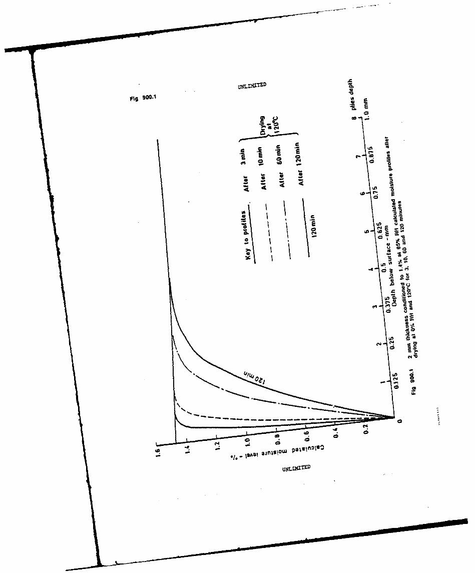
fig 900.1
00
Z ar40 N
6)l
I.'.
- - - -- -- -- -- - - - -0
400
ci6
et c
*naE

UN-NU4IT!D Fig 900.2
I g-
C S4
U'o
E Ea, , a
Culc a' Cio
UNI * UE
88 UNLnafTED
901 METHOD OF ASSESSMENT OF DIFFUSIVITY PROPERTIES OF FIBRE RELNFORCEDPLASTICS
1 Description
This data sheet contains recommendations for the determination of the
moisture diffusivity characteristics of a given material.
These recomendations are not restricted to any particular material or
generation of materials, except in as much as the limits quoted on the condition-ing and drying temperatures may have to be altered for the new developing resin
systems. Unless convincing evidence to the contrary is produced hence or other-
vise it is suggested that the guidelines evolved for the present generation of
resins be retained until the necessary data is generated.
2 Method
2.1 Specimen size and sample size
Because the actual moisture content is never more than a few percent
of the total weight, it is clearly undesirable from an accuracy viewpoint
to monitor it using small coupons such as the ILSS specimen. The
reco mended number of plies is that which gives a nominal thickness of
2 mm (this would be 16 for a ply thickness of 0.125 ma). 75 mm is
recomended for both length and width and the specimen is illustrated in
Fig 901.1. The large length/width to thickness ratio is also valuable in
reducing the effect of diffusion in directions other than through the
thickness (edge effects). A tolerance of t1 ma on length/vidth and
±t0.2 ma on thickness is allowable.
Applications where the diffusion coefficients in other directions are
required are regarded as special cases and outside the scope of this
data sheet.
A sample size of 3 is recommended.
2.2 Pre-experimental exposure
Moisture is readily taken up by dry laminates when they are exposed
to the laboratory atmosphere. Diffusion parameters deduced from tests
where the pre-experimental exposure is significant may be appreciably in
error and every effort should be made to minimise this parameter. Vacuum
storage or sealing in metalised polythene or aluminium bags is recommended.
UNLIMITED

UNLLMITED 39
It is mandatory to determine the zero weight datum. In order to
determine this the specimens should be dried to constant weight, i-medi-
ately prior to the commencement of exposure, irrespective of the method
of storage employed.
2.3 Weighing procedure and moisture uptake determination
Weighings should always be ade as soon as possible following with-
drawal from the conditioning chamber/oven. However, it is essential to
remove any surface moisture using a dry cloth or tissue. The balance
doors should be closed while weighing and long tweezers used to handle the
specimens. Draughts and body heat effects can induce appreciable distor-
tion into the readings. The balance should be capable of measuring to
±0001 Sm. It is important that specimens and travellers spend the minimum
time outside the conditioning environment and that the conditioning chamber
is managed so that it is opened for the minimum time possible on the minimum
number of occasions.
Knowing both the wet and dry weights ww and wd respectively, the
percentage uptake of water by weight, M , can be found from
- (w - wd) 100(
wd
2.4 Conditioning and drying temperatures
These recomendations stem from Ref 2 and are based on the principle
that a transition tempe'ature appears to exist for all resins at higher
values than which non-Fickian absorption/desorption behaviour is observed.
It is not therefore recommended that these temperatures be exceeded unless
convincing evidence has been obtained in justification.
The recommended maximum conditioning temperatures are 700C for 1800C
cure systems and 450 C for 120 0 C cure systems. For drying it is recommended
that a vacuum oven be used set no higher than 700 C.
For some new materials the temperatures recommended may be too high,
while for others designed for improved elevated temperature properties
higher conditioning temperatures may be acceptable. In order to investi-
gate these possibilities it is suggested that a pilot experiment be carried
out using a single specimen of dimensions 50 x 50 x t mm where t rep-
resents the thickness (0.5 mm non) of a 4-ply 0/90 symmetric lay-up.
UNLIMITED

90 UNILIMITED
Starting at 70°C, the pilot experiment should be repeated at temperatures
lower by 5 C (ie 70°C, 65°C, 6009 etc) until Fickian behaviour is observed.
Fig 2 illustrates a typical Fickian plot of moisture against the square
root of time. If Fickian behaviour is observed at 700C the same procedure
can be followed at successively higher temperatures (ie 700C, 750 C, ecc)
until non-Fickian behaviour is produced. For 1200C cure materials the
starting temperature should be 45°C. However, some apparent deviations
from Fickian behaviour may arise merely from the small net weight and
rapid approach to saturation of the pilot specimen.
2.5 Test matrix (including lay-ups)
It is recomended that the same tests are carried out using u/d and
00/900 symmetric lay-ups.
It is recommended that the absorptivity be determined at a minimm
of three different relative humidities, eg 70Z, 85% and 952. The accept-
able tolerance on humidity is +5%. The tolerance on temperature is ±2 0 C.
In order to explore the relationship between absorptivity and relative
humidity, it may be required to perform experiments at a number of other
humidity levels. The use of either conditioning cabinets or salt solutions
is acceptable provided the tolerances on humidity and temperature are
maintained throughout. Similarly in order to explore the relationship
between temperature and diffusivity it may be required to perform experi-
ments at a number of temperatures below the recommended maximum.
2.6 Frequency of weighings
Fig 901.2 shows a typical Fickian plot of moisture content against
the square root of time. It will be seen that the rate of moisture uptake
decreases fairly rapidly with time, so that a higher frequency of weighings
is required in the early stages.
it is recommended that if possible the experiment commences on a
Monday morning. At least three weighings should be made on the first day
and at least two during the remainder of the first week. At least one
weighing should be made each day during the second eek, followed by a
gradual decrease in frequency as the rate of weight increase diminishes.
2.7 Determination of 'levelling-off' and of diffusion parameters
The determination of the equilibrium concentration, represented by
the height of the flat portion of Fig 901.2 at large values of time,
UNLIMITED

UNLIMITED 9t
requires a definition of 'levelling-off' in terms of permissible difference
between maximum and minimum moisture content measurements over a given
period of time. A similarly shaped curve showing weight loss against the
square root of time results from drying out.
It is recomended that levelling-off be defined as no greater vari-
ation than *0.5Z in moisture content (i *0.005Z of composite weight for
a saturation level of 1.0% moisture) over a period of time which is a
function of conditioning temperature and material thickness and during
which at least three weighings should be made.
For 180 0 C cure systems it is recomended that at 700 C and for 2 --
thickness this period should be three weeks. For other thicknesses and
conditioning temperatures the recomended period is given by:-
t2 (2)154210 --(
where W a dwell time in weeks
t - specimen thickness (mm)
T a absolute conditioning temperature (oK).
For 1200 C cure systems it is recommended that at 45 0 C and for 2 mm
thickness the period should be 3 weeks. The corresponding formula for
other thicknesses &ud conditioning temperatures is:-
t(3)
The diffusion coefficient is determined from the straight line
portion of Fig 901.2 at the lower values of time. Following Ref 3 the
diffusion coefficient, D , is given by:-
D r ( t(M2, MI) 2 (4)T 6_ .- / 2 , T1
where MWa equilibrium concentration
MI . moisture uptake after time T1
M2 = moisture uptake after time T2
t - thickness.
UNLIMITED

92 UNLIMITED
To give a better estimate of the one-dimensional diffusion coef-
ficient D- , a correction factor given by Shen and Springer 4 can be used
giving:-
* D
(1 +)
2.8 Measurement of moisture gradients
The moisture gradient through-the-thickness can be measured by using
the slicing technique described in Ref 3. By this means the time required
to determine M can be shortened as the outer plies will always saturate
first.
2.9 Volume fraction
It is recommended that the fibre volume fraction be as near to 60%
as possible. Results obtained using material of different volume fractions
can, however, be normalised to a 60% Vf value using the method given in
Ref 5.
3 Test report
The test report should include the following particulars:-
(a) Complete identification of the material tested, including fibre and
resin type, date and method of manufacture, lay-up, stacking sequence, batch
number, void content, volume fraction and any previous history.
(b) Sample dimensions.
(c) A complete tabular and graphical representation of all the experi-
mental sampling, including any pilot experiments.
(d) The diffusion parameters D and M- deduced from the test results.
(e) Date of commencement and conclusion of test.
4 References
1 E.C. Edge. The effect on moisture absorption experiments of failure
to dry specimens prior to exposure. Composites 11, No.2, pp 101-104,
April 1980.
2 Environmental effects in the testing of composite structures in
aircraft. Report to CRAG. Ref. BAe-MSM-R-GEN-0603, June 1985.
UNLIMITED
UNLnaTED 93
3 S.M. Copley and T.A. Collings. The determination of through-
thickness moisture distribution and diffusion coefficients in fibre
reinforced plastic laminates. RAE Technical Report 81105,
August 1981.
4 C. Shen and G.S. Springer. Moisture absorption and desorption in
coMposite materials. J. Comp. Mat. 10, pp 2-20, 1976.
5 CRAG W.G. on Test Methods. Method 900. Background information on
environmental effects.
UNLIMITED

Fig 901.1 UNLnTED
7S 1 mm
Z 2 220.2mm
I- anthickness(Number of ptiesgive as neat to2mm thicknessas Possibt)
Fig 901.1 Recommended test specimen for the determination of diffusion parameters
UNMIITEED

tMhLADITED Fig 901.2
CLC
C U'
E E
~E
0
IA
Ln C
U , U
EEU .~N
Co M
Culo v- sioUNLIITE

96 Mnaf(TRD
902 METHOD OF CONDITIONING OF FIBRE REINFORCED PIASTICS UNDER ROT/WET
ENVIROMETS
1 General
For the purpose of this method it is assumed that test specimens will be
coupons or simple structural elements of uniform thickness (1-4 mm) which will
be used to establish mechanical behaviour over a range of uniform moisture con-
tents and temperature levels. Situations involving changes in thickness, built
up structure and testing involving moisture gradient* will need more complex
strategies and the reader is referred to Raf 1, where moisture absorption is
discussed in more detail. It is assumed that moisture will be gained or lost
through all surfaces of the test section and that moisture content will be
determined by weight changes.
Specimens may be fitted with and tabs involving the use of other materials
and adhesives. Some testing will be long term and may involve elevated tempera-
ture levels. Temperature differences may exist between the test section and its
ends gripped in testing machines. Damage may accumlate during long term test
sequences. These factors make the monitoring of moisture content by the weighing
of specimens inaccurate and inconvenient and the use of travellers for this
purpose is now widely accepted.
2 Traveller requirements
Travellers are required to monitor specimen moisture content by weighing.
They should be cut from the saw board adjacent to the specimen involved and will
therefore be of the same lay-up, thickness, batch and have experienced the same
processing sequence. Traveller width and length should be comparable with the
specimen test section involved, provided that an accuracy in moisture content
determination of t1% can be obtained. Where this is not the case (in small or
thin specimens) the traveller width and length should be increased. For specimen
thicknesses of 1 and 2 me, travellers of 45 45 m and 30 x 30 mm respectively
are recomeended. Each specimen should be provided with its own traveller which
should accompany it at all times throughout its environmental history of manu-
facture, storage, pre-conditioning and testing so that weight changes may be
monitored.
Composite material will absorb moisture from the environment as soon as it
is exposed after processing. To limit this, storage in vacuum, at room tempera-
ture, of material, specimens and travellers is recommended. Alternatively
bagging in sealed impervious bags containing desiccant may be adopted. Even so
UNLIMITED
u Ln IS I "I t

UNLD1ITED 97
some moisture absorption can be anticipated and a moisture content datum must be
established. It is therefore recoumended that additional secondary travellers
be provided to establish the moisture content at the start of the pre-conditioning
phase by drying them in a vacuum oven at that time to constant weight at an
approved temperature level (see section 4).
It .,ould be noted that where specimens are required for testing in the
'as received' or the dry condition secondary travellers will not be required.
3 Pre-couditionina
Current policy is to pre-condition to equilibrium at a constant relative
humidity (RE) equivalent to overall service usage in the environment of interest.
Comparisons between material systems with differing moisture absorption charac-
teristics are then possible since each would arrive at its own moisture content
appropriate to a common sequence of usage. A RE of 851 is recomended to
represent the worst world-wide average usage while the dry condition, although
not representative of service conditions forms a convenient datum level which is
widely used. Intermediate levels may be required for further material charac-
terisation and it is recommended that these should be representative of actual
usage. 70Z RH has been used for temperate environments while desert conditions
at low RR levels may also be of interest.
4 Temperature levels for drying and pre-conditioning
Drying and pre-conditioning may be accelerated by raising the temperature
level but care is necessary since damage may be produced if temperature levels
are too high (see method 901). Ref I recomends maximum temperature levels of
60 0 C and 45°C for current thermosetting materials processed at 1800C and 1200C
respectively. Other material systems may have different limits but the tempera-
ture levels quoted above should not be exceeded unless sufficient evidence has
been obtained to justify it.
5 Monitoring of drying and pre-conditioning
It is recomended that both specimens and travellers be removed from the
conditioning environment when travellers are weighed to determine moisture con-
tent. Surfaces should be wiped using a dry cloth or tissue and travellers should
be weighed, after cooling to room temperature, using an analytical balance capable
of measuring to 0.0001 gn. Balance doors should be closed during weighing and
travellers should be handled using long tweezers. Weighing should be carried
out at approximately equal intervals of Vtime, (see method 901). Conditioning
UNLIMITED
98 UL .TED
to the 100% equilibrium moisture content and its confirmation is costly in terms
of time and it is therefore recoinnded that the 95% level should be adopted
based on three successive measurements exceeding this value. It should be noted
that this requirement implies knowledge of the 100% level either from initialexperimental work on identical travellers or from a prediction, based on a dif-
fusion coefficient derived from initial moisture uptake and subsequently confirmed
experimentally. It is important that specimens and travellers spend the minimum
time outside the conditioning environment and that the conditioning chamber is
managed so that it is opened for the minimaz time possible on the minimum number
of occasions.
Where both primary and secondary travellers are involved, simultaneous
moisture conditoning and drying will be necessary. During these procedures the
percentage moisture (M), loss or gain, can be monitored relative to the common
starting condition as follows:-
M (W2 - ,I)
where W1 is the weight at the start and W2 is the current weight of the
traveller (primary or secondary) being recorded. When the secondary traveller
has been completely dried the initial percentage moisture content will be known
and may then be used to calculate the dry weight of the prime traveller. Thetotal percentage moisture content (M), relative to the dry condition, can sub-
sequently be found from:
MT-(Wy - WD) ,10
WD
where Wp is the current weight of the primary traveller and WD is its calcu-
lated weight in the fully dried condition.
Where specimens are not immediately required for testing they may be stored
in the pre-conditioning environment with routine weight monitoring until required.
On removal for testing the traveller should accompany its specimen so that moni-toring can continue throughout life.
When testing at elevated temperatures significant moisture loss can occur
especially if an extended time period is involved and special measures may be
required to maintain moisture content .
UNLIMITED

UNLLZaTED 99
6 Pre-conditioning and teat records
Recording of environmental history should include the following particulars.
(a) Material identification comprising fibre and resin type, lay-up,
stacking sequence, batch number and previous history.
(b) Traveller and specimen identification, dimensions and fibre volume
fraction.
(c) Pre-conditioning sequence including relative humidity, temperature
and time.
(d) Tabulated, measured weights and derived moisture contents, dates,
pre- and poet-conditioning storage conditions.
(e) Mechanical test details including date, environmental sequence with
times and pre- and post-test traveller weights and moisture contents.
(f) Traveller dry out details.
7 References
1 Environmental effects in the testing of composite structures in
aircraft. Report to CRAG, Ref BAe-MSM-R-GEN-0603, June 1985.
UNLIMITED
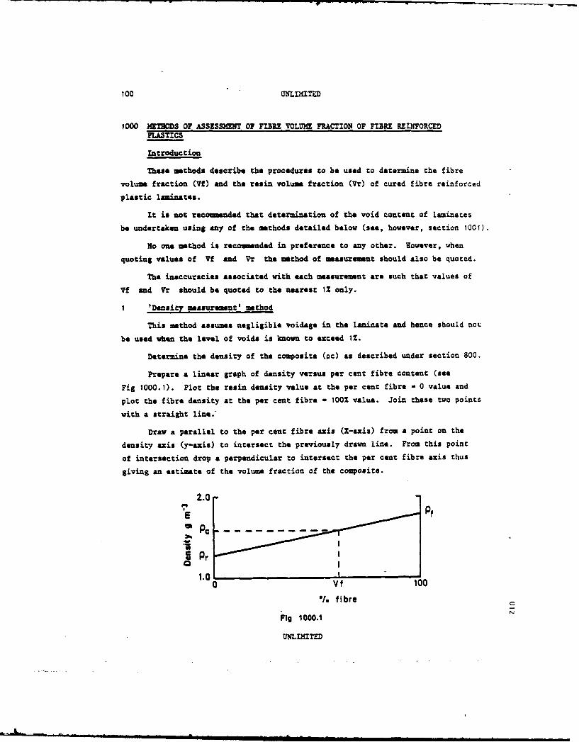
100 UNL..IT.D
1000 METHODS OF ASSESSM ENT OF FIBRE VOLUME FRACTION OF FIBRE REWORCEDPLASTICS
introduction
These methods describe the procedures to be used to determine the fibre
volume fraction (Vf) and the resin volume fraction (Vr) of cured fibre reinforced
plastic laminates.
It is not recominded that determination of the void content of laminates
be undertaken using any of the methods detailed below (see, however, section 1001).
No one method is recoumnded in preference to any other. However, when
quoting values of Vf and Vr the method of measurement should also be quoted.
The inaccuracies associated with each measurement are such that values of
Vf and Vr should be quoted to the nearest 12 only.
I 'Density measurement' method
This method assumes negligible voidage in the laminate and hence should not
be used when the level of voids is known to exceed 1%.
Determine the density of the composite (oc) as described under section 800.
Prepare a linear graph of density versus per cent fibre content (see
Fig 1000.1). Plot the resin density value at the per cent fibre a 0 value and
plot the fibre density at the per cent fibre - 100% value. Join these two points
with a straight line.
Draw a parallel to the per cent fibre axis (X-axis) from a point on the
density axis (y-axis) to intersect the previously drawn line. From this point
of intersection drop a perpendicular to intersect the per cent fibre axis thus
giving an estimate of the volume fraction of the composite.
1.0
-PPf
I
C Pr
0 Vf 100
0/. fibre
Fig 1000.1
UJNLIMITED
UNLL aTED 101
where oc - composite density g/n
of a fibre density g/m
or - resin density g/m.
NOTE: fibre and resin density should be obtained from the suppliers release
documentation.
The raiiin volume fraction may be ootained from the following:-
VT(Z) - tO0 - Vf
2 'Thickness measurement' method
Obtain the average thickness of the sample. At least five measurements
should be made along the length of the sample. Correction may need to be made
for excess surface resin, such as that introduced by a peel ply during
manufacture.
The fibre volume fraction of the sample may be obtained from the following:-
Vf(Z) - N x Np1t xo
where N - number of plies in the laminate
Mp - pre-impregnate fibre weight per unit area (g/m) (1)
t - laminate thickness (.m)
of - fibre density (g/m) (2)
NOTES: (1) The pre-Lmpregnate fibre weight may be obtained from either
the suppliers release documentation or by direct measurement from
a sample taken from an area adjacent to that area of pre-impregnate
used in the manufacture of the laminate.
(2) Fibre density should be obtained from the suppliers release
documentation.
The resin volume fraction may be obtained from the following:-
Vr(z) - 100 - Vf
3 'Resin removal' method
Determine the density of the composite sample (oc) as described under
section 800.
Determine the mass of the composite sample (c).
UNLfMITED

102 UNL1TED
Determine the mass of the fibre in the composite sample (Mf). This may be
done in one of three ways depending upon the system being investigated.
(a) Sulphuric acid/hydrogen peroxide digestion
Place the specimen in a 500 al conical beaker and add 20 ml of concentrated
sulphuric acid. Gently heat the beaker until the acid begins to fume, then reduce
heat and leave to digest for a few minutes (do not allow volume to become too
small as bumping may occur). Carefully add 30 ml of 100 volume hydrogen peroxide,
drop wisa at first, faster when reaction is nearing completion. If solution is
still brown, further 5 ml portions shall be added at one drop par second until
the solution becomes clear.
Boil the resulting mixture for 10 minutes. Allow the solution to cool.
Weigh a clean, dry, scintered glass crucible (porosity 3) Wi. Filter
digestion mixture through the scintered glass crucible using a Buchner filtration
flask and pump (take care not to loose any fibre), washing the beaker thoroughly
with distilled water.
Wash fibre in scintered crucible until filtrate is neutral to universal
indicator paper.
Use pump to remove as much liquid as possible, before drying the crucible
plus fibre at 125-1500 C for approximately 45 minutes. Care must be taken to
avoid any loss of fibre.
Allow to cool to room temperature in desiccator then weigh the crucible
plus contents W2.
(b) Nitric acid digestion
Place the specimen in a beaker containing at least 50ml of concentrated
nitric acid.
Neat the acid to boiling point and hold for 60-90 minutes. Allow the
solution to cool.
Weigh a clean, dry, scintered glass crucible (porosity 3) Wi. Filter
digestion mixture through the scintered glass crucible using a Buchner filtration
flask and pump (take care not to loose any fibre), washing the beaker thoroughly
with distilled water. Repeat this process this time washing the beaker thoroughly
with acetone.
Proceed as in (a) above to obtain the weight of the crucible plus contents
(W2).
UNLIXMTED

ULLfITED 103
To allow for any loss of fibre due to oxidation by the acid, a BLANK,
comprising a known weight of fibre should follow an identical 'digestion' path
to that defined in either (a) or (b) above. The percentage loss of weight may
be defined as:
Mb - 100(W3 - W4)/W3
where W3 - original fibre weight (g)
W4 - final fibre weight after 'digestion' (g).
The mass of the fibre (corrected for any weight loss due to oxidation by
the acid) is defined as:
Mf - (W2-W)/(100 - b) (g)
(c) Resin burn-off
This method should not be used for CPI.
Place the sample in an oven pre-heated to 580-6000 C. Allow resin to burn-
off for at least I hour or until all traces of blackness on the sample have dis-
appeared. Remove the fibres from the oven and allow to cool to room temperature
in a desiccator. Obtain the mass of the fibres (Mf).
Calculations
The fibre volume fraction can be calculated from the following:-
V OOMfoc
The resin volume fraction can be calculated from the following:-
100(1 - Mf)pcVr) - Mxr
NOTE: fibre and resin density should be obtained from the suppliers release
documentation.
All weight measurements should be made to the nearest milligram.
UNLIMITED

104 Un.Z TZD
1001 METBOD Of ASSESSMIENT OF VOID VOLUME FRACTION OF FIBRE RELNFORCED PLASTICSBY ULTRASONIC SCANING
Introduction
This data sheet, which is an advisory document only, describes & procedure
for the assessmnt of void content of a lainate by ultrasonic scanning technique.
The procedure is valid for single through transmission using two probes, double
through transmission using a plate glass reflector and double through transmission
using the back surface of the laminate when it is smooth.
Equipment constraints
The following constraints with regard to equipment used for scanning of
laminates is suggested.
(a) Beam anale - normality
The ultrasonic beam must be normal to the material surface within00
:3 . A reflector plate when used mst be normal to the beam within ±t ° .
(b) Scannin speed
Scanning speed is limited by the rate at which data can be retrieved
and plotted. If the scan rate is too fast, then data plotted on a forward-
running scan across an article will not match data plotted from the return
run.
When an analog" signal is impressed on sensitive paper, scanning
speed should not exceed 40 cm/second. Speed when using robotic scanning
has been demonstrated at 65 cm/second satisfactorily but may be constrained
by the speed at which the computer gathers and processes information.
(c) Noise
Ultrasonic noise is caused by water turbulence and is usually pro-
duced when water jets are used to couple the material to the transducers.
Turbulence is caused primarily by air bubbles within the transducer housing
and should be reduced to below ±1 dB before attempting to scan. Noise can
be seen on the cathode ray tube. Electronic noise can be minimised by
reducing the amplifier gain control setting.
Misalignment of the probes will also contribute. It is important to
normalize each probe individually to obtain the best top surface echo before
sliding the probes in-line to obtain coincidence.
UNLIMITED

UNLIMITED 105
(d) Probes and interface equipment
Probe performance has been shown to be age dependent. It is therefore
necessary to carry out regular checks on probes to determine their useful
life by monitoring their performance against a known standard.
Tests have also indicated that calibration of probes is also depen-
ant upon the interface equipment used and therefore similar probes or
interfacing equipment cannot be interchanged without re-calibrating the
equipment set up.
Ultrasonic scanning of composite
Ultrasonic scanning as a means of determining the quality of composite
components has been used for some considerable time usually in conjunction with
a hard copy printout which shows che overall quality of the component. The copy
usually in different tones between black and white or in several colours are
representation of the ultrasonic attenuation of the area being scanned.
The attenuation at any position is dependent on several factors, ie surface
texture, void, delamination and the cure reaction of the resin and fibre/resin
interface. The attenuation value is also dependent on thickness of the component
and therefore several density tones can be attributed to one attenuation level
on a varying thickness component indicating varying levels of quality.
Of the parameters affecting the attenuation level of a composite the effect
of thickness can be assumed to be linear and can be taken into account in deter-
mining quality. The cure of the resin and fibre resin interface has a minimal
effect and can therefore be disregarded. Surface loss is dependent on the surface
texture of the component and is independent of thickness, however errors in
surface losses when applied to thin components, ie less than 1.5 - can seriously
affect void volume estimates.
Determination of surface losses and attenuation coefficients
A procedure for determining the above parameters is described in Ref 1.
However it is recomended that the stepped laminate (Fig 1001.1) be fabricated
in varying thickness and not ground from a constant thickness plate since surface
losses are dependent on surface texture. Detail scan the panel to determine the
lowest attenuation for each thickness using different frequency probes.
Plotting the lowest attenuation value against thickness for each frequency
probe should give a graph of several linearly increasing lines (one for each
UNLIMITED

106 UNLI1TED
frequency probe used) originating from one point at zero thickness. This value
is the value attributed to surface loss.
The slope of the .lines also gives the attenuation coefficient at zero void
volume in dB/rm for each frequency probe used.
Correlation of void content with attenuation
To correlate the void content against attenuation levels it is necessary to
have constant thickness panels with varying attenuation level indicating therefore
varying quality standards. Detail scan the panels using probes of different
frequency and extract specimens 12 mm x 5 me from areas of constant attenuation.
Determine the void content of the extracted specimens using the acid diges-
tion technique as described in Method 1000.
An alternative method of correlating void content against attenuation is
using through thickness examination using either Quantimet or quantitative micro-
scopic examination (point count method). It is advisable to repeat the measure-
ments several times polishing the specimen after each measurement to give a
volumtric assessment.
A graph of the void content against attenuation level is shown in
Fig 1001.2.
R ference
I D.E.W. Store. Non-destructive determination of the void content in
carbon fibre reinforced plastics by measurement of ultrasonic
attenuation. RAE Technical Report 74162 (1974).
UNLIMITED

UNLfl4TED 107
Typical thickness range: 0.75 to 6 m
Fig 1001.1 Five step laminate
UNLIaMIE

108 UInTE
U.O. (Cross-Ptied)
2 /
cc/
z, Pain Weave/
/
UI- /
m , .-- '8-Harness Satin.
% VOID VOLUME
Fig 1001.2 Relat:ionship between void volumeand specific attenuation
uMMMTED
i N J m ll-lii~il l Il ime i E i - | III Ii i; '

REPORT DOCtIENTATION PAC.EOverall security clssiicaion of this page
I U~=LITED
As far as possible this page should contain only unclassified information. If it is necessary to enter classified informnatiun. tilt b','abcve must be marked to indicate the classification, e.g. Restricted. Confidential or Secret.
I. DRIC Reference 2. Originator's Reference 3. Aency 4. Report Security ClassiticationiMakin(to be added by DRIC) Reference
RAE TR 88012 UI4LII D
5. DRIC Code for Or*inator 6. Origi tator (Corporate Author) Name and Location
7673000W Royal Aerospace .stablishment,Farnborough, Hants, UK
Sa. Sponsoring Ager..y's Code 6a. Sponsoring Agency (Contract Authority) Name and Locztion
_ _ _ __ii_ _ _ _ __l
7. Title CRLG test methods for th]e mlasurinent of the euginering properties of~.re inforced plastics
7a. (For Translations) Tite in Foreign Ls 4uWg
7b. (Fo~r Conference Papers) Title, Place and Date of Conference
8. Author 1. Surname. Initials .Author 2 9b. Authors 3,4.... 10. Cate Pq's Refs.Curtis, P.T. Febt-4ar7 f08 101988
I. Contract Number 12. Period 13. Project 14. Other Reference Nos.Materials/Structures
218
i5. Distribution statement(a) Controlled by -
(b) Special limitations (if any) -If it is intended that a copy of this document shail be released ovenme refer to RAE Lefeit No.3 to Supplement 6 ofMOD Manual 4.
16. Descriptors (K"eords) (Descriptons marid are selected from TEST)
17. Abstract
.This Report is the third and final issue of a docment describing test methodssuitable for the measurement of the engineering properties and other associatedproperties of fibre reinforced plastics. Specimen configurations and testingprocedures are detailed and the applicability of the tests to the different typesof fibre reinforced plastics is discussed.
,i,.i