Embed Size (px)
Citation preview

7/27/2019 Crank Angle Encoder
http://slidepdf.com/reader/full/crank-angle-encoder 1/4
0 0 0 - 3 6 6 e - 0 4 . 0
2
( D B 1 9 .
2 6 1 3 B e )
Kistler Instrumente AG, PO Box, CH-8408 Winterthur
Tel +41 52-224 11 11, Fax 224 14 14, [email protected], www.kistler.com
This information corresponds to the current state of knowledge. Kistler reserves
the right to make technical changes. Liability for consequential damage resul-
ting from the use of Kistler products is excluded.
The crank angle encoder type 2613B provides the basis for all
crank-angle-related measurements of internal combustion
engines. It consists of an angle encoder, a signal conditioner
and a line terminator. It generates 3 TTL rectangular-pulse
signals: A crank angle signal with adjustable resolution
(0,1°...6°), a crank-angle-related trigger signal, and another
crank angle signal with fixed resolution (1°), which can be
used for the engine management system or the engine speed
at the test bench. The crank angle encoder is suitable for use
together with most engine indicating systems.
• speed range 1 ... 20’000 rpm• very rugged, resists high mechanical loading
• conforming to™
Crank Angle Encoder
Page 1/4
Technical Data
TTL crank angle signal
Resolution º 0,1 ... 6
Dynamic accuracy
at 10'000 rpm
(signal delay) º +0,02
TTL trigger signal (TRG)
Resolution º 0,1 ... 6
Speed range rpm 1 ... 20'000
Operating temperature range
Encoder and amplifier ºC -30 ... 60Connection flange ºC -30 ... 100
Power supply
with stabilized voltage V DC 5 ±0,25
Current consumption mA 200
with unstablilized voltage V DC 6 ... 24
Current consumption mA 200 ... 400
Mounting diameter
of encoder mm 69
Encoder weight g 460
Amplifier dimensions mm 98x64x37
Amplifier weight g 300
Description
The crank angle encoder contains a precision marker disk with
a trigger mark and 360 angle marks which are scanned by a
transmission photoelectric cell. Their light intensity is regula-
ted in order to compensate for any soiling. The disk and the
photoelectric cell are encased in a dustproof housing.
With its wide speed range of 1 ... 20’000 rpm the encoder can
be used on a large variety of engines. Even 1 rpm of the
crankshaft can be measured correctly.
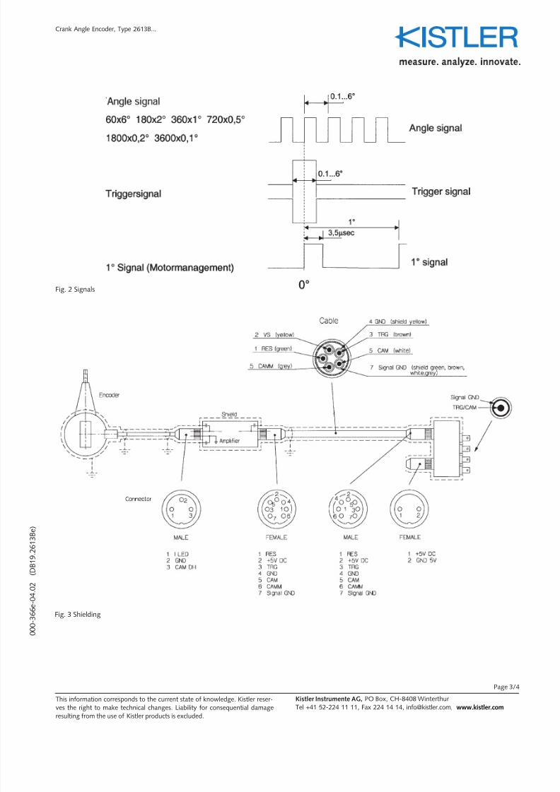
The separate amplifier is connected by means of a 1,5 m long
cable. It is powered by a 5 VDC power supply and suppliesone TTL-compatible output signal each for the trigger marker
and angle markers (Fig. 2).
The line terminator contains a circuit, which protects the sig-
nal and generates an additional crank angle signal with fixed
resolution, which can be used for the engine management
system or the engine speed at the test bench.
Accessories – XEV
Type 2613B...

7/27/2019 Crank Angle Encoder
http://slidepdf.com/reader/full/crank-angle-encoder 2/4
0 0 0 - 3 6 6 e - 0 4 . 0
2
( D B 1 9 . 2
6 1 3 B e )
Crank Angle Encoder, Type 2613B...
Kistler Instrumente AG, PO Box, CH-8408 Winterthur
Tel +41 52-224 11 11, Fax 224 14 14, [email protected], www.kistler.com
This information corresponds to the current state of knowledge. Kistler reserves
the right to make technical changes. Liability for consequential damage resul-
ting from the use of Kistler products is excluded.
Page 2/4
The required resolution of the crank angle signal is set by DIL-
switches in the signal conditioner. If required the resolution
can also be set by the remote-control-unit type 2613B5
(accessories).
The cable, the amplifier and the line terminator are shielded in
order to reduce electromagnetic sensitivity (Fig. 3)
The Type 2613B crank angle encoder is ideal for many appli-
cations owing to its compact measurements and extended
speed range. An important feature is the simple replaceability
of the cable with its sensor. The device is compatible to AVL
measuring chains.
Application
The crank angle encoder is used wherever motor angle and
flow information is needed, especially for calculating IMEPand heat release. An extremely exact alignment (ca. 0,1°) of
top dead centre of each cylinder to the trigger signal of the
encoder is decisive for precise indication (TDC determination).
Installation
The crank angle encoder should be mounted directly on the
free end of the crankshaft, insofar as this is possible.
Consequently, the free end must be fitted with a 6-hole flan-
ge (Fig. 1). Mounting the crank angle encoder to a shaft
downstream of the crankshaft may lead to errors as the result
of play or torsional movement. In addition, the encoder must
be precisely centred in order to prevent vibration.
The encoder can be mounted at any angle. The encoder
housing is then attached to a rigid part of the engine via the
securing arm and positioning rod. Prior to a series of measu-
rements, the TDC position is determined as the angle bet-
ween the trigger marker of the encoder and the physical TDC
of the cylinder to be measured. Two common methods are
either employing the capacitive TDC encoder or by pressure
measurement in the motored engine.
If ground-isolated installation of the amplifier is desired, then
it has to be mounted using an isolating plate.
Fig. 1 System overview
7/27/2019 Crank Angle Encoder
http://slidepdf.com/reader/full/crank-angle-encoder 3/4
0 0 0 - 3 6 6 e - 0 4 . 0
2
( D B 1 9 . 2
6 1 3 B e )
Kistler Instrumente AG, PO Box, CH-8408 Winterthur
Tel +41 52-224 11 11, Fax 224 14 14, [email protected], www.kistler.comThis information corresponds to the current state of knowledge. Kistler reser-
ves the right to make technical changes. Liability for consequential damage
resulting from the use of Kistler products is excluded.
Page 3/4
Crank Angle Encoder, Type 2613B...
Fig. 3 Shielding
Fig. 2 Signals

7/27/2019 Crank Angle Encoder
http://slidepdf.com/reader/full/crank-angle-encoder 4/4
0 0 0 - 3 6 6 e - 0 4 . 0
2
( D B 1 9 . 2
6 1 3 B e )
Kistler Instrumente AG, PO Box, CH-8408 Winterthur
Tel +41 52-224 11 11, Fax 224 14 14, [email protected], www.kistler.comThis information corresponds to the current state of knowledge. Kistler reser-
ves the right to make technical changes. Liability for consequential damage
resulting from the use of Kistler products is excluded.
Page 4/4
Crank Angle Encoder, Type 2613B...
Accessories Type
Remote control unit 2613B5
AVL adapter cable 2613B6
Scope of delivery Type
Crank angle encoder 2613B1
Signal conditioner 2613B2
Connecting cable 10 m 2613B3
Line terminator 2613B4
Centring disk 5.015.063
Connecting rod 5.015.057
6x6hex. screw M5 x 10 6.140.049
6x6hex. screw M6 x 10 6.140.050
Fixing disk M5 6.230.082
Fixing disk M6 6.230.085
Fork wrench SW8/10 5.210.370
Hex. key SW2 5.210.371
Hex. key SW2,5 5.210.120
Female cable connector 5.511.320
(2-pin, 680 series) (Cable Ø 6-8 mm)