Embed Size (px)
Citation preview
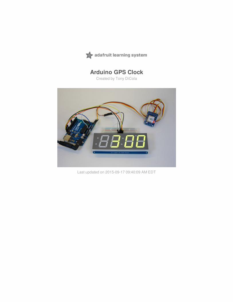
Arduino GPS ClockCreated by Tony DiCola
Last updated on 2015-09-17 09:40:09 AM EDT
23568
111215
Guide Contents
Guide ContentsOverviewHardwareGPS Clock WiringDS1307 Real Time Clock WiringSoftwareGPS Clock SketchDS1307 Real Time Clock Sketch
© Adafruit Industries https://learn.adafruit.com/arduino-clock Page 2 of 18
Overview
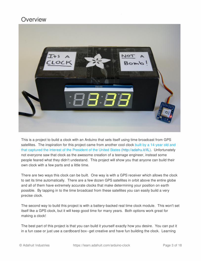
This is a project to build a clock with an Arduino that sets itself using time broadcast from GPSsatellites. The inspiration for this project came from another cool clock built by a 14-year old andthat captured the interest of the President of the United States (http://adafru.it/ifL). Unfortunatelynot everyone saw that clock as the awesome creation of a teenage engineer, instead somepeople feared what they didn't undestand. This project will show you that anyone can build theirown clock with a few parts and a little time.
There are two ways this clock can be built. One way is with a GPS receiver which allows the clockto set its time automatically. There are a few dozen GPS satellites in orbit above the entire globeand all of them have extremely accurate clocks that make determining your position on earthpossible. By tapping in to the time broadcast from these satellites you can easily build a veryprecise clock.
The second way to build this project is with a battery-backed real time clock module. This won't setitself like a GPS clock, but it will keep good time for many years. Both options work great formaking a clock!
The best part of this project is that you can build it yourself exactly how you desire. You can put itin a fun case or just use a cardboard box--get creative and have fun building the clock. Learning
© Adafruit Industries https://learn.adafruit.com/arduino-clock Page 3 of 18

and making things yourself is something to celebrate and encourage in people of all ages. Whoknows maybe you'll build a clock that's so cool the President wants to see it too!
© Adafruit Industries https://learn.adafruit.com/arduino-clock Page 4 of 18

Hardware
To build this clock you'll need the following hardware and tools:
An Arduino Uno (http://adafru.it/50) or compatible like the Metro 328 (http://adafru.it/2488). You can actually use other Arduinos like the Leonardo, Mega, etc. but you might need tomake small changes to the code when using GPS (see the GPSguide (http://adafru.it/ifM) and examples).A 7-segment LED backpack display (http://adafru.it/ifN). Either the 1.2" (big one, at the topof the photo above) or 0.56" (middle display in image) will work. You could also use a 14-segment quad alphanumeric display, but it doesn't have a colon so it won't make a greatclock (but it is great for displaying text or more complex output). The code for this project ismade to use the 7-segment display.A time source, one of the following:
The ultimate GPS shield (http://adafru.it/1272) or breakout (http://adafru.it/746). If youuse GPS then the clock will set itself based on the time from GPS satellites. You'llneed to make sure the clock can get a good view of the sky for it to get a GPS fix. Youalso probably want to add a coin cell battery to the GPS board (http://adafru.it/ifO) sothat it remembers the time even when it loses the satellite signal.A battery-backed real time clock like the DS1307 (http://adafru.it/264). This is acheaper option than GPS but it will need to have its time set once ahead of time (then
© Adafruit Industries https://learn.adafruit.com/arduino-clock Page 5 of 18
it will remember the time as long as the battery lasts, which is usually many years!). The ChronoDot (http://adafru.it/255) is another nice real time clock. This guide willshow how to use the DS1307. Be aware the DS1307 requires a little more solderingand assembly than the GPS shield or breakout.
Breadboard (http://adafru.it/64) and jumper wires (http://adafru.it/153).An enclosure for the clock--the box your parts arrive in or any other small cardboard boxworks great. You can get as fancy or as simple as you want with an enclosure. You couldeven leave everything bare to showcase your work!Soldering tools (http://adafru.it/136). You'll need to solder the 7-segment display together,and solder the GPS or real time clock module. If you're new to soldering don't worry it's notdifficult--with a little patience and practice you'll be a pro in no time. Be sure to read theAdafruit guide to excellent soldering (http://adafru.it/dWK) and practice on some spare partsto get the hang of it.Power supply (http://adafru.it/63) for the Arduino. You can plug in any 7-12 volt supply oreven a small battery pack (http://adafru.it/67) to power the clock. I recommend a plug inpower supply since the clock won't run for very long on batteries.
Once you have all the parts you'll first need to build the 7-segment display and GPS or real timeclock module. Carefully follow the guides for each of these components to assemble and testthem:
Adafruit LED Backpack Guide (http://adafru.it/ifP)Adafruit Ultimate GPS Breakout Guide (http://adafru.it/ifM)Adafruit Ultimate GPS Shield Guide (http://adafru.it/ifQ)Adafruit DS1307 Guide (http://adafru.it/fyi)
Be sure to check that the basic examples for each component work before you move forward withassembling the clock. It will be much easier to debug issues with each component in isolationinstead of when they're assembled into the clock!
Once you're ready to wire up the clock follow the right section below depending on the hardwarethat you're using, either the GPS or DS1307 real time clock.
GPS Clock WiringTo build the clock with GPS support wire the components together as shown in the diagram below.
Note that this diagram only shows the ultimate GPS breakout. For the GPS shield ignore all thewires going to the GPS breakout and instead connect the GPS shield to the Arduino and thenconnect the 7-segment display to the GPS shield/Arduino as shown in the diagram (you might needto solder the wires to the open row of GPIOs next to the GPS shield's headers, or solder stackingheaders (http://adafru.it/85) to the GPS shield).
© Adafruit Industries https://learn.adafruit.com/arduino-clock Page 6 of 18

Connect Arduino 5V to 7-segment +/VIN power pin and ultimate GPS breakout VIN pin(red wires).If using the larger 1.2" 7-segment display connect Arduino 5V to 7-segment IO pin(don't worry the 0.56" display doesn't have this pin).Connect Arduino GND to 7-segment -/GND ground pin and ultimate GPS breakout GNDpin (black wires).Connect Arduino A5 or SCL to 7-segment C/clock pin (yellow wire).Connect Arduino A4 or SDA to 7-segment D/data pin (orange wire).Connect Arduino D8 to ultimate GPS breakout TX pin (blue wire).Connect Arduino D7 to ultimate GPS breakout RX pin (green wire).
Once you've wired everything together it should look something like the following:
© Adafruit Industries https://learn.adafruit.com/arduino-clock Page 7 of 18
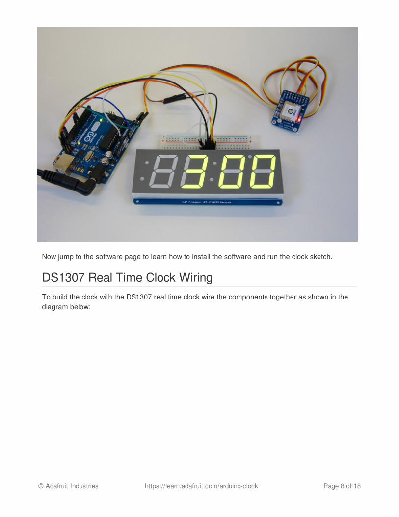
Now jump to the software page to learn how to install the software and run the clock sketch.
DS1307 Real Time Clock WiringTo build the clock with the DS1307 real time clock wire the components together as shown in thediagram below:
© Adafruit Industries https://learn.adafruit.com/arduino-clock Page 8 of 18

Connect Arduino 5V to 7-segment +/VIN power pin and DS1307 5V pin.If using the larger 1.2" 7-segment display connect Arduino 5V to 7-segment IO pin(don't worry the 0.56" display doesn't have this pin).Connect Arduino GND to 7-segment -/GND ground pin and DS1307 GND pin.Connect Arduino A5 or SCL to 7-segment C/clock pin and DS1307 SCL pin.Connect Arduino A4 or SDA to 7-segment D/data pin and DS1307 SDA pin.
Once you've wired everything together it should look something like the following:
© Adafruit Industries https://learn.adafruit.com/arduino-clock Page 9 of 18
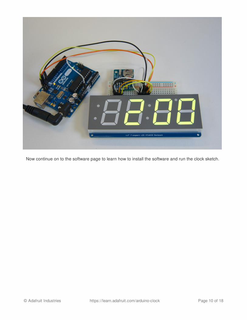
Now continue on to the software page to learn how to install the software and run the clock sketch.
© Adafruit Industries https://learn.adafruit.com/arduino-clock Page 10 of 18
SoftwareTo use the clock sketch you'll want to make sure you're using the latest version of the ArduinoIDE (http://adafru.it/fvm) (1.6.5 at the time of this writing).
If you're totally new to Arduino take a little time to go through some introductory tutorials like how tomake a LED blink (http://adafru.it/eir). This will help you understand how to use the IDE, load asketch, and upload code.
Next you'll need to make sure the libraries used by the sketch are installed. With the latest ArduinoIDE you can use its library manager (http://adafru.it/fCN) to easily install libraries, or check out thisguide on how to manually install a library (http://adafru.it/egP). You'll want to install the followinglibraries:
Adafruit LED Backpack Library (http://adafru.it/aLI)Adafruit GFX Library (http://adafru.it/aJa)Adafruit GPS Library (http://adafru.it/aMm) (if using GPS)Adafruit RTClib Library (http://adafru.it/c7r) (if using the DS1307)
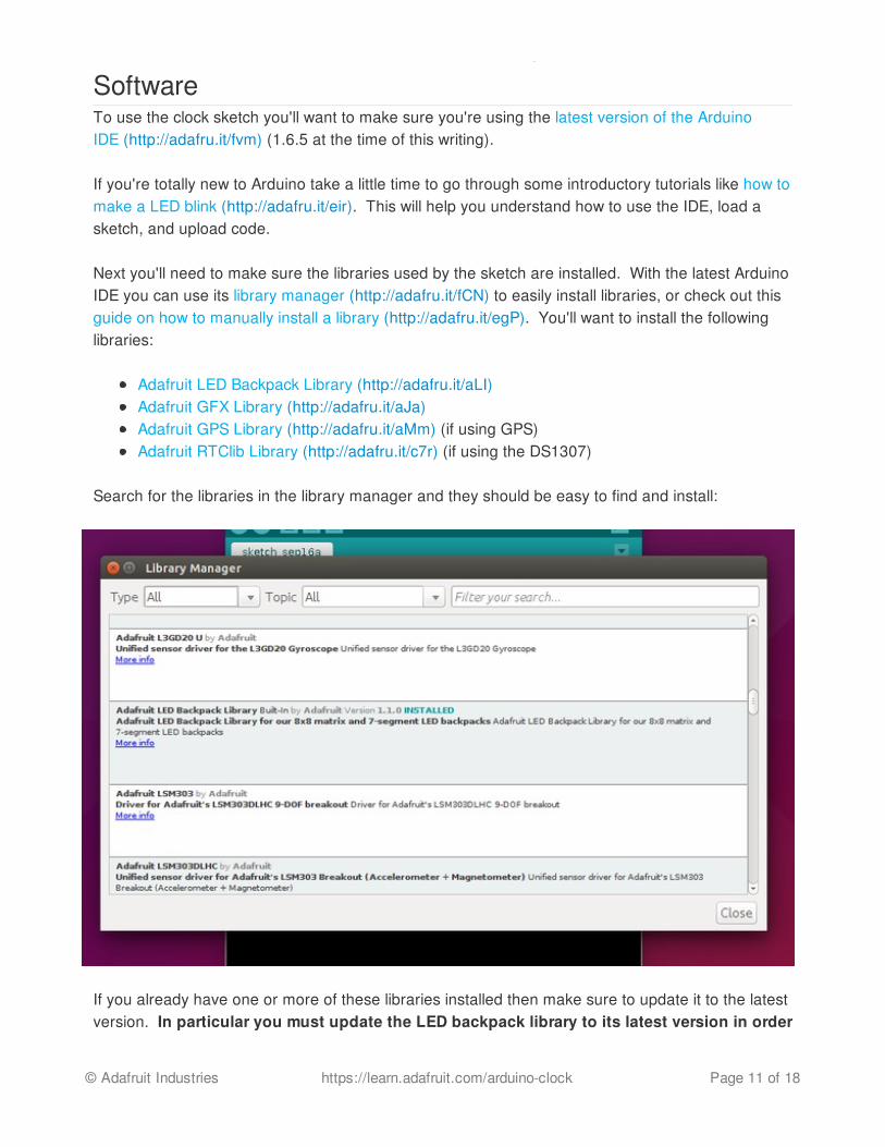
Search for the libraries in the library manager and they should be easy to find and install:
If you already have one or more of these libraries installed then make sure to update it to the latestversion. In particular you must update the LED backpack library to its latest version in order
© Adafruit Industries https://learn.adafruit.com/arduino-clock Page 11 of 18
to get the clock sketches!
Now follow the appropriate section below depending on if you're using GPS or the DS1307.
GPS Clock SketchTo load the GPS clock sketch make sure the hardware is wired together, the libraries above areinstalled, and the Arduino is connected to the computer through a USB cable. Then select the File-> Examples -> Adafruit LED Backpack Library -> clock_sevenseg_gps example. You shouldsee something like the following loaded in the IDE:
© Adafruit Industries https://learn.adafruit.com/arduino-clock Page 12 of 18

There are two things you might want to change in the sketch before you upload it to the Arduino. The first is if the clock uses 24-hour or 12-hour time format. By default the clock uses 12-hourformat and it's set by this line:
// Set to false to display time in 12 hour format, or true to use 24 hour:#define TIME_24_HOUR false
© Adafruit Industries https://learn.adafruit.com/arduino-clock Page 13 of 18

If you'd like to use 24-hour time change the line to set the define as true, like:
The second thing you might want to change is the local time offset. The time from GPS satellites isin GMT or UTC universal time, but your local time is probably different. You can use a site likeworldtimeserver.com (http://adafru.it/ifR) or this Wikipedia page (http://adafru.it/ifS) to find what theoffset, or difference, is between GMT/UTC time and your local time.
By default the sketch uses UTC-7 time, or the US Pacific timezone in daylight savings time. If youare in the US Eastern timezone you'd want to change this value to UTC-4. To change the localtime offset find this part of the code:
And change it to a new offset, like -4 for US Eastern in daylight savings time:
Now save your modified example and you're ready to upload it to the Arduino. Make sure underthe Tools -> Board menu the Arduino Uno is selected, and under the Tools -> Port menu theserial port for the Arduino is selected (it should say Arduino Uno). Then press the upload buttonor click the Sketch -> Upload item to send the code to the Arduino. Woo-hoo the clock sketchshould be running!
Once the clock sketch is loaded you'll need to wait for the GPS to get a satellite lock before the timewill accurately be displayed. If you look at the GPS breakout or shield you should see a fastblinking red LED (blinking once a second) when the GPS is acquiring a fix. Once the GPS has a
// Set to false to display time in 12 hour format, or true to use 24 hour:#define TIME_24_HOUR true
// Offset the hours from UTC (universal time) to your local time by changing// this value. The GPS time will be in UTC so lookup the offset for your// local time from a site like:// https://en.wikipedia.org/wiki/List_of_UTC_time_offsets// This value, -7, will set the time to UTC-7 or Pacific Standard Time during// daylight savings time.#define HOUR_OFFSET -7
// Offset the hours from UTC (universal time) to your local time by changing// this value. The GPS time will be in UTC so lookup the offset for your// local time from a site like:// https://en.wikipedia.org/wiki/List_of_UTC_time_offsets// This value, -7, will set the time to UTC-7 or Pacific Standard Time during// daylight savings time.#define HOUR_OFFSET -4
© Adafruit Industries https://learn.adafruit.com/arduino-clock Page 14 of 18
satellite fix the LED will slow down and blink once every 15 seconds. Make sure the GPS breakoutor shield has a clear view of the sky in order to acquire a fix. It can take anywhere from 45seconds to 30 minutes to get a fix, depending on the location and view of the sky.
If you haven't done it already consider adding a coin cell battery to the GPS (http://adafru.it/ifO) sothat it can save the time. This will let you read a good time value from the GPS even when it hasn'tacquired a satellite fix.
Congratulations you've successfully built a GPS clock!
DS1307 Real Time Clock SketchTo load the DS1307 clock sketch make sure the hardware is wired together, the libraries above areinstalled, and the Arduino is connected to the computer through a USB cable. Then select the File-> Examples -> Adafruit LED Backpack Library -> clock_sevenseg_ds1307 example. Youshould see something like the following loaded in the IDE:
© Adafruit Industries https://learn.adafruit.com/arduino-clock Page 15 of 18
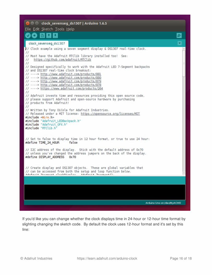
If you'd like you can change whether the clock displays time in 24-hour or 12-hour time format byslighting changing the sketch code. By default the clock uses 12-hour format and it's set by thisline:
© Adafruit Industries https://learn.adafruit.com/arduino-clock Page 16 of 18

If you'd like to use 24-hour time change the line to set the define as true, like:
That's it! There isn't anything else you normally need to change in the sketch.
Now save your modified example and you're ready to upload it to the Arduino. Make sure underthe Tools -> Board menu the Arduino Uno is selected, and under the Tools -> Port menu theserial port for the Arduino is selected (it should say Arduino Uno). Then press the upload buttonor click the Sketch -> Upload item to send the code to the Arduino. Woo-hoo the clock sketchshould be running!
If this is the first time you've used the DS1307 it will automatically set its time based on the time thesketch was compiled and uploaded. However you can manually set the time by finding this part ofthe sketch in the setup function:
Notice the comments mention how to manually set the time. For example to set the time toJanuary 21, 2014 make the code look like:
// Set to false to display time in 12 hour format, or true to use 24 hour:#define TIME_24_HOUR false
// Set to false to display time in 12 hour format, or true to use 24 hour:#define TIME_24_HOUR true
// Set the DS1307 clock if it hasn't been set before.bool setClockTime = !rtc.isrunning();// Alternatively you can force the clock to be set again by// uncommenting this line://setClockTime = true;if (setClockTime) { Serial.println("Setting DS1307 time!"); // This line sets the DS1307 time to the exact date and time the // sketch was compiled: rtc.adjust(DateTime(F(__DATE__), F(__TIME__))); // Alternatively you can set the RTC with an explicit date & time, // for example to set January 21, 2014 at 3am you would uncomment: //rtc.adjust(DateTime(2014, 1, 21, 3, 0, 0));}
© Adafruit Industries https://learn.adafruit.com/arduino-clock Page 17 of 18

Upload the sketch again and the time should be changed. That's all there is to using the DS1307real time clock!
Congratulations you've successfully built an Arduino clock using the DS1307!
// Set the DS1307 clock if it hasn't been set before.bool setClockTime = !rtc.isrunning();// Alternatively you can force the clock to be set again by// uncommenting this line:setClockTime = true;if (setClockTime) { Serial.println("Setting DS1307 time!"); // This line sets the DS1307 time to the exact date and time the // sketch was compiled: //rtc.adjust(DateTime(F(__DATE__), F(__TIME__))); // Alternatively you can set the RTC with an explicit date & time, // for example to set January 21, 2014 at 3am you would uncomment: rtc.adjust(DateTime(2014, 1, 21, 3, 0, 0));}
© Adafruit Industries Last Updated: 2015-09-17 09:40:10 AM EDT Page 18 of 18