Embed Size (px)
Citation preview
Cryogenic Heat Switch
A Senior Design Project
Submitted to the Faculty of the
Department of Mechanical Engineering California Polytechnic State University
San Luis Obispo
In Partial Fulfillment of the Requirements for the Degree
Mechanical Engineering, Bachelor of Science
Associates:
Daniel Brodkey
Esteban Ruiz
Cristal Vasquez
Date: June 4, 2012
©2012

ii
Statement of Disclaimer
Since this project is a result of a class assignment, it has been graded and accepted as fulfillment of the
course requirements. Acceptance does not imply technical accuracy or reliability. Any use of
information in this report is done at the risk of the user. These risks may include catastrophic failure of
the device or infringement of patent or copyright laws. California Polytechnic State University at San
Luis Obispo and its staff cannot be held liable for any use or misuse of the project.

iii
June 4, 2012
Team Boreas
1 Grand Avenue
San Luis Obispo, CA 93405
Professor Mohammad Noori
Mechanical Engineering Department
California Polytechnic State University
San Luis Obispo, CA 93405
Dear Professor Noori:
Attached is a copy of the Senior Project report: Development of a conceptual design for a cryogenic heat
switch, for the Jet Propulsion Laboratory.
Sincerely,
Team Boreas
Distribution:
Professor Joseph D. Mello: 1 copy

iv
June 4, 2012
Team Boreas
1 Grand Avenue
San Luis Obispo, CA 93405
Eugenio Urquiza, Ph.D.
Cryogenic Systems Engineering
Jet Propulsion Laboratory
Pasadena, CA 91109
Dear Mr. Urquiza:
Attached is a copy of the Senior Project report: Development of a conceptual design for a cryogenic heat
switch, for the Jet Propulsion Laboratory.
Sincerely,
Team Boreas
Distribution:
Supervisor Jose I. Rodriguez: 1 copy
v
Contents I. Table of Figures .................................................................................................................................... vi
II. Abstract ................................................................................................................................................. 7
III. Introduction .......................................................................................................................................... 7
A. Objective ........................................................................................................................................... 7
IV. Background and Literature Review..................................................................................................... 10
V. Design Development ........................................................................................................................... 12
A. Designs Overview ............................................................................................................................ 13
B. Analysis ........................................................................................................................................... 15
C. Preliminary Testing ......................................................................................................................... 17
VI. Final Design ......................................................................................................................................... 24
VII. Design Realization ............................................................................................................................... 25
VIII. Design Verification Plan ...................................................................................................................... 26
IX. Project Management Plan .................................................................................................................. 29
X. Conclusion ........................................................................................................................................... 29
XI. References .......................................................................................................................................... 32
XII. Appendices ......................................................................................................................................... 33
A. Morphological Attributes List ......................................................................................................... 33
B. Conceptual Designs ......................................................................................................................... 35
C. List of Vendors ................................................................................................................................ 43
D. Vendor-Supplied Specifications and Data Sheets ........................................................................... 44
E. EES Thermal Analysis ...................................................................................................................... 46
F. Gantt Chart...................................................................................................................................... 60
G. Test Equipment ............................................................................................................................... 64
XIII. Acknowledgements ............................................................................................................................ 64
vi
I. Table of Figures Figure 1. System diagram of heat switch with a failed cryocooler. .............................................................. 9
Figure 2. System diagram of heat switch with cryocooler being irradiated by the sun. .............................. 9
Figure 3. System diagram of a heat switch with the cryocooler cooling the detector to its operating
temperature. ................................................................................................................................................. 9
Figure 4. COT Heat Switch. .......................................................................................................................... 10
Figure 5. Heat conductance versus pressure. ............................................................................................. 11
Figure 6. Schematic and equivalent thermal circuit of the gas gap heat. .................................................. 11
Figure 7. Draft model of ferromagnet heat switch. .................................................................................... 13
Figure 8. Draft model of original ferromagnet heat switch. ....................................................................... 14
Figure 9. Draft model of SMA heat switch. ................................................................................................. 14
Figure 10. Draft of thermally decoupled SMA heat switch. ........................................................................ 15
Figure 11. Results for various linear interpolations. ................................................................................... 16
Figure 12. Schematic of test setup for neodymium magnets. .................................................................... 17
Figure 13. Actual test set up used to test magnet's temperature dependence. ........................................ 18
Figure 14. Wooden soft jaw and thermocouples. ...................................................................................... 18
Figure 15. Plot of pressure versus temperature for ¾ x ¾ x 1/16 in neodymium magnets. ...................... 19
Figure 16. Plot of pressure versus temperature for 1 x ½ x 1/32 in neodymium magnets. Magnets
featured irreversible damage beyond 100°C. ............................................................................................. 20
Figure 17. Plot of pressure versus temperature for the pairs of ¾ x 3/8 x 1/32 in neodymium magnets on
aluminum plates. ........................................................................................................................................ 21
Figure 18. Schematic of test setup for shape memory alloys. .................................................................... 21
Figure 19. Actual test bed for nitinol spring and Fexinol®. ......................................................................... 22
Figure 20. Nitinol spring in set up. Flexinol® wire had similar position. ..................................................... 22
Figure 21. Magnetic force decreases, as magnets are further away from each other. .............................. 24
Figure 22. CNC milling process for machining the channel used to house the magnets. ........................... 25
Figure 23. Final prototype used to test magnetic actuation. ..................................................................... 26
Figure 24. First iteration of proof-of-concept prototype. ........................................................................... 27
Figure 25. Original springs used. Right spring is before deformation, left spring is after deformation. .... 27
Figure 26. Springs acquired after initial springs deformed. Top spring is Pt.#B6-50 and bottom spring is
Pt.#80559S. ................................................................................................................................................. 28
7
II. Abstract A prototype cryogenic heat switch capable of transferring heat at cryogenic temperatures, while
decoupling to prevent irreversible heat damage and minimizing parasitic heat loads, is to be developed
for the Jet Propulsion Laboratory. Various material properties and cryogenic heat transfer processes will
be investigated to determine the best solution for this project. A working proof of concept model will be
constructed that may eventually be integrated onto a spacecraft’s passive cooler systems to protect
them from the irradiation emitted by the sun, from the albedo of planets, and other malicious heat
sources.
III. Introduction The Jet Propulsion Laboratory (JPL) has issued this project to develop a prototype cryogenic heat switch
capable of transferring heat at cryogenic temperatures. Cryogenic heat switches have several potential
uses in space application. They are capable of minimizing parasitic losses from an “OFF” cryocooler in a
redundant cryocooler system, as well as decouple from the cryoradiator when irradiated by the sun, or
albedo of planets. What made this project extremely challenging is that material properties at cryogenic
temperatures are convoluted, esoteric, and highly non-linear.
The goal of this project was to design a prototype cryogenic heat switch that is more reliable and
efficient than the current state of the art designs. Extensive research led to the design and building of a
conceptual prototype that was tested as a proof of concept. The initial step was to research the topics of
interest in order to come up with an innovative and feasible (promising) design. Further research and
analysis have been done to verify it will meet the requirements. The prototype has been built and tested
in standard pressure and temperature.
Testing and analysis has proven validity of the design and the results have been presented to the JPL
group that supported this project so that they may choose to implement it on their passive cooler
systems. This prototype may be used by JPL and possibly other space agencies, since it is designed to
protect passive coolers from excess heat due to irradiation of the sun, albedo from the planets, and
other malicious heat sources. Furthermore, most spacecraft systems have passive coolers and this
process is widely used.
In the search for a new conceptual design of a cryogenic heat switch for JPL, two unique solutions
initially seemed feasible. The activation mechanism was developed through a systems engineering
approach by first understanding the requirements, physical system and environment. Such an approach
helped to consolidate the designs options and clarify parameters.
A. Objective At the completion of this project a conceptual heat switch prototype will be tested for proof of concept.
This conceptual prototype will be applicable to various space applications and conducive to several
8
design implementations. Furthermore, the conceptual model will provide an efficient means of
transferring heat in the “ON” (closed) state, reliable “ON/OFF” switching capabilities, while mitigating
parasitic heat losses in the “OFF” (open) state.
Implementing a system engineering approach to this design has facilitated a better understanding of this
difficult challenge and has assisted in the development of conceptual models. It has promoted
conceptualizing various scenarios, understanding the primary concerns, and subsequently optimizing for
such cases. Furthermore, understanding the primary requirements and specifications helped establish
certain design considerations.
Requirements:
· Low-outgassing materials (Vacuum Pressure < 1X 10E-4 torr)
· Off Conductance < .5mW/K
· On Conductance > 100mW/K
· Closed from 100K-300K
· Power Dissipation < 20 mW
· Lifetime > 5 yrs
· Lifetime > 100 cycles
· Conducts only heat not electricity
· Needs to couple and decouple between cryocooler and detector
Preferences:
· Passive system
· No moving parts
· Small in size
Environmental Conditions:
· T∞= 293K (temperature of electronics surrounding the switch)
· TCold Space= 2.7K (never 0K because of microwave background radiation)
· Solar Irradiance at 1 AU from the sun is ~1380 W/m2
Purpose:
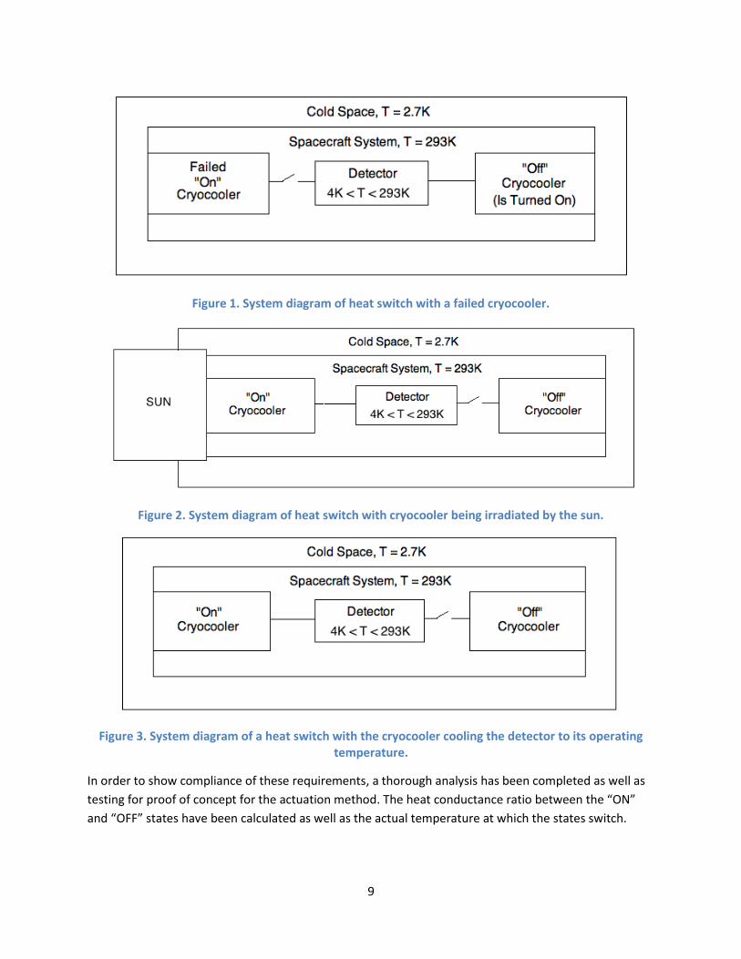
· Couple/De-couple from a failed cryocooler to minimize parasitic heat losses. (See figure 1)
· Couple/De-couple from a cryocooler if/when irradiated by the sun or other malicious heat
sources. (See figure 2)
· Couple/De-couple from a redundant cryocooler to minimize parasitic heat losses. (See figure 3)
· Detector is cooled (anywhere from 5K to 100K, we will assume this heat switch is for a detector
with a 100K operational temperature) to get precise wavelength measurements by removing IR
radiation
· Detector is heated (to about 293K) to decontaminate itself (or to boil off any ice water that may
have accumulated on the detector)
9
Figure 1. System diagram of heat switch with a failed cryocooler.
Figure 2. System diagram of heat switch with cryocooler being irradiated by the sun.
Figure 3. System diagram of a heat switch with the cryocooler cooling the detector to its operating temperature.
In order to show compliance of these requirements, a thorough analysis has been completed as well as
testing for proof of concept for the actuation method. The heat conductance ratio between the “ON”
and “OFF” states have been calculated as well as the actual temperature at which the states switch.
10
IV. Background and Literature Review In space applications, heat transfer is a critical parameter to the function, reliability, and overall life of
any object in space. Depending on the objects location relative to the earth, sun, and other stellar
bodies, it will experience drastic temperature changes. Electrical devices and other various components
are sensitive to such drastic temperature variations, which may impede their functionality and need to
be maintained at relatively constant temperatures. Furthermore, the operating temperatures for many
of these devices are within a range of 20K to 150K. This range is better known as the cryogenic
temperature region.
Cryogenics is a relatively new field of study that originated at the turn of the 20th century. In essence,
this term describes the study of extremely low temperatures and encompasses a wide array of subjects
and fields of study. Initially, the field of cryogenics was dominated by physicists who developed the
methods of obtaining such low temperatures and tested the behavior of various elements at these
conditions [1]. However, as the means for obtaining and maintaining cryogenic conditions became more
practical, engineers began exploring its potential with the hopes of applying this new knowledge.
Physical properties of matter such as conductance and heat capacity behave queerly at cryogenic
temperatures. Furthermore, many of these properties are highly nonlinear and become functions of
temperature [2].
As satellites or other objects in space become irradiated (e.g. the sun) the same methods that keep
components cool in effect transform into heaters. To maintain the integrity of the space systems this
malignant heating effect must be controlled and limited. Furthermore, the uses of redundant
cryocooling systems require a means of switching between coolers if one fails. In order to save precious
power in space, the mitigation of parasitic heat losses is crucial. Currently, JPL use room temperature
heat switches in various space applications to turn heat transfer “ON” and “OFF” from different
components. At around temperatures below 300K, the switch will be turned “ON” and have a heat
conductance of 100mW/K and above 300K the switch will be “OFF”, which in theory completely
mitigates heat transfer.
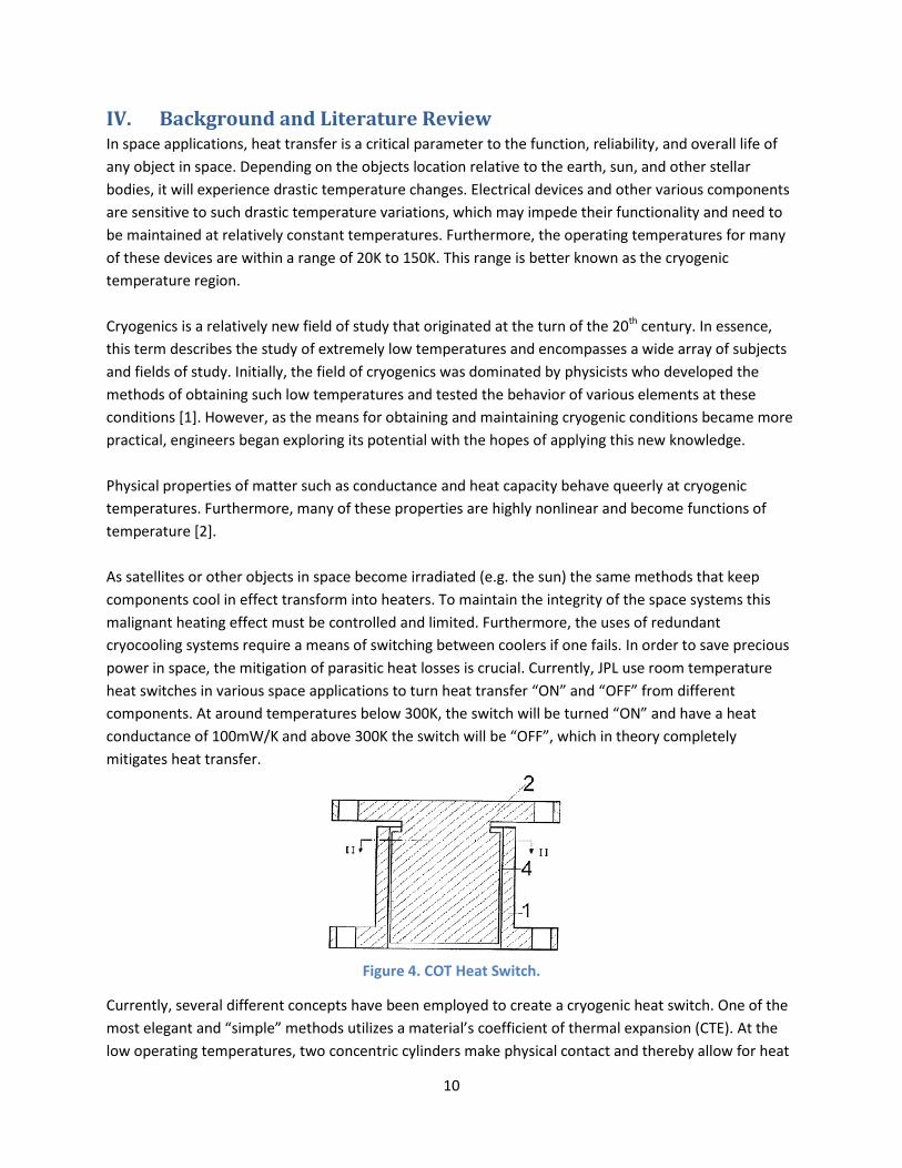
Figure 4. COT Heat Switch.
Currently, several different concepts have been employed to create a cryogenic heat switch. One of the
most elegant and “simple” methods utilizes a material’s coefficient of thermal expansion (CTE). At the
low operating temperatures, two concentric cylinders make physical contact and thereby allow for heat
11
transfer. With higher temperatures the materials begin to expand and open up a physical gap that
drastically inhibits the transfer of heat. This type of heat switch is not designed for cryogenic
temperatures and only work at or above room temperature. Figure 4 above demonstrates this concept
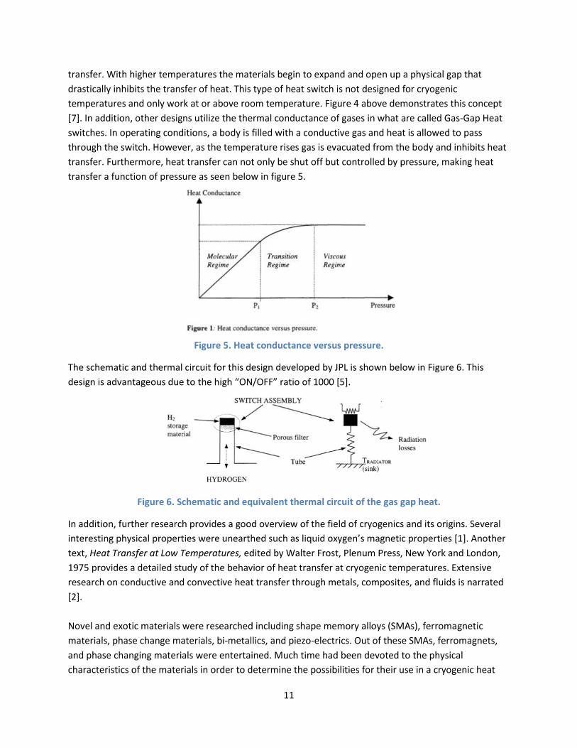
[7]. In addition, other designs utilize the thermal conductance of gases in what are called Gas-Gap Heat
switches. In operating conditions, a body is filled with a conductive gas and heat is allowed to pass
through the switch. However, as the temperature rises gas is evacuated from the body and inhibits heat
transfer. Furthermore, heat transfer can not only be shut off but controlled by pressure, making heat
transfer a function of pressure as seen below in figure 5.
Figure 5. Heat conductance versus pressure.
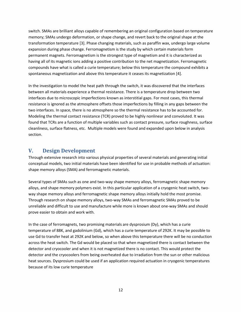
The schematic and thermal circuit for this design developed by JPL is shown below in Figure 6. This
design is advantageous due to the high “ON/OFF” ratio of 1000 [5].
Figure 6. Schematic and equivalent thermal circuit of the gas gap heat.
In addition, further research provides a good overview of the field of cryogenics and its origins. Several
interesting physical properties were unearthed such as liquid oxygen’s magnetic properties [1]. Another
text, Heat Transfer at Low Temperatures, edited by Walter Frost, Plenum Press, New York and London,
1975 provides a detailed study of the behavior of heat transfer at cryogenic temperatures. Extensive
research on conductive and convective heat transfer through metals, composites, and fluids is narrated
[2].
Novel and exotic materials were researched including shape memory alloys (SMAs), ferromagnetic
materials, phase change materials, bi-metallics, and piezo-electrics. Out of these SMAs, ferromagnets,
and phase changing materials were entertained. Much time had been devoted to the physical
characteristics of the materials in order to determine the possibilities for their use in a cryogenic heat
12
switch. SMAs are brilliant alloys capable of remembering an original configuration based on temperature
memory; SMAs undergo deformation, or shape change, and revert back to the original shape at the
transformation temperature [3]. Phase changing materials, such as paraffin wax, undergo large volume
expansion during phase change. Ferromagnetism is the study by which certain materials form
permanent magnets. Ferromagnetism is the strongest type of magnetism and it is characterized as
having all of its magnetic ions adding a positive contribution to the net magnetization. Ferromagnetic
compounds have what is called a curie temperature; below this temperature the compound exhibits a
spontaneous magnetization and above this temperature it ceases its magnetization [4].
In the investigation to model the heat path through the switch, it was discovered that the interfaces
between all materials experience a thermal resistance. There is a temperature drop between two
interfaces due to microscopic imperfections known as interstitial gaps. For most cases, this thermal
resistance is ignored as the atmosphere offsets those imperfections by filling in any gaps between the
two interfaces. In space, there is no atmosphere so the thermal resistance has to be accounted for.
Modeling the thermal contact resistance (TCR) proved to be highly nonlinear and convoluted. It was
found that TCRs are a function of multiple variables such as contact pressure, surface roughness, surface
cleanliness, surface flatness, etc. Multiple models were found and expanded upon below in analysis
section.
V. Design Development Through extensive research into various physical properties of several materials and generating initial
conceptual models, two initial materials have been identified for use in probable methods of actuation:
shape memory alloys (SMA) and ferromagnetic materials.
Several types of SMAs such as one and two-way shape memory alloys, ferromagnetic shape memory
alloys, and shape memory polymers exist. In this particular application of a cryogenic heat switch, two-
way shape memory alloys and ferromagnetic shape memory alloys initially hold the most promise.
Through research on shape memory alloys, two-way SMAs and ferromagnetic SMAs proved to be
unreliable and difficult to use and manufacture while more is known about one-way SMAs and should
prove easier to obtain and work with.
In the case of ferromagnets, two promising materials are dysprosium (Dy), which has a curie
temperature of 88K, and gadolinium (Gd), which has a curie temperature of 292K. It may be possible to
use Gd to transfer heat at 292K and below, so when above this temperature there will be no conduction
across the heat switch. The Gd would be placed so that when magnetized there is contact between the
detector and cryocooler and when it is not magnetized there is no contact. This would protect the
detector and the cryocoolers from being overheated due to irradiation from the sun or other malicious
heat sources. Dysprosium could be used if an application required actuation in cryogenic temperatures
because of its low curie temperature
13
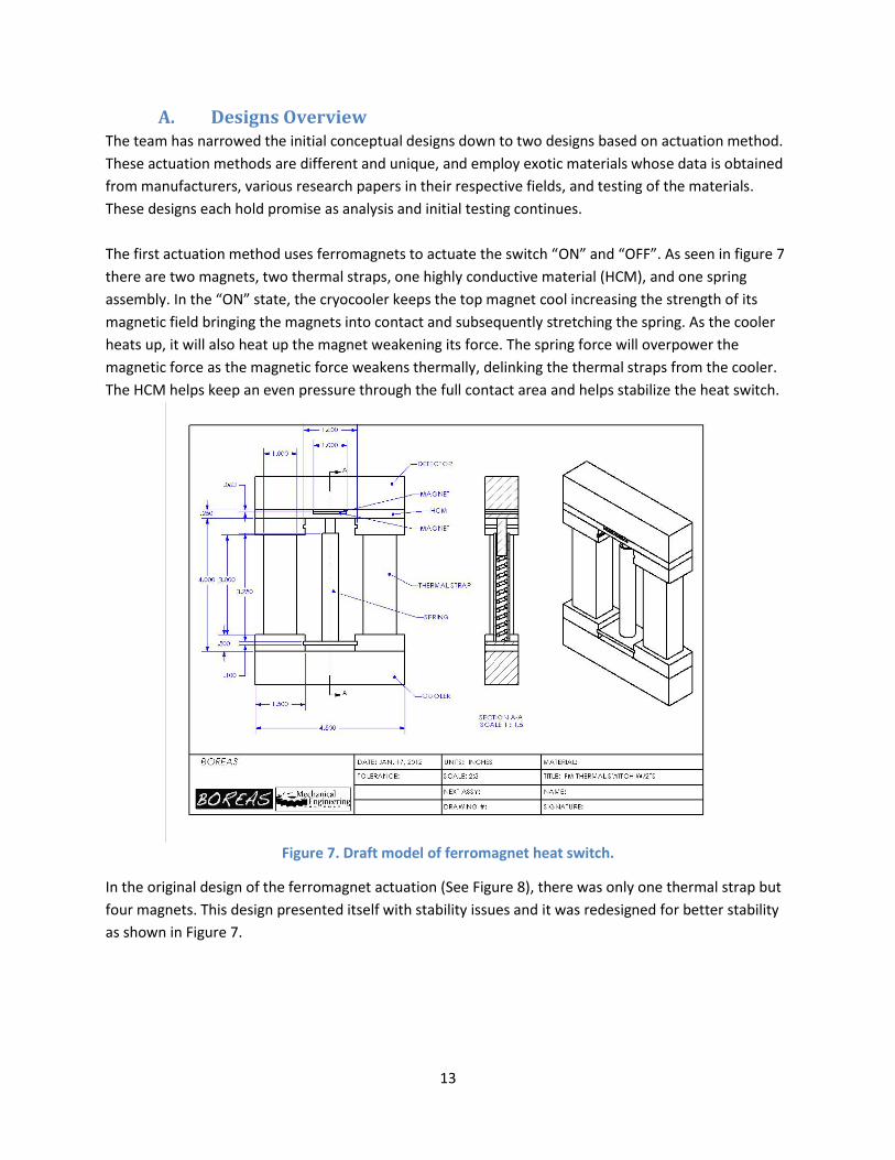
A. Designs Overview The team has narrowed the initial conceptual designs down to two designs based on actuation method.
These actuation methods are different and unique, and employ exotic materials whose data is obtained
from manufacturers, various research papers in their respective fields, and testing of the materials.
These designs each hold promise as analysis and initial testing continues.
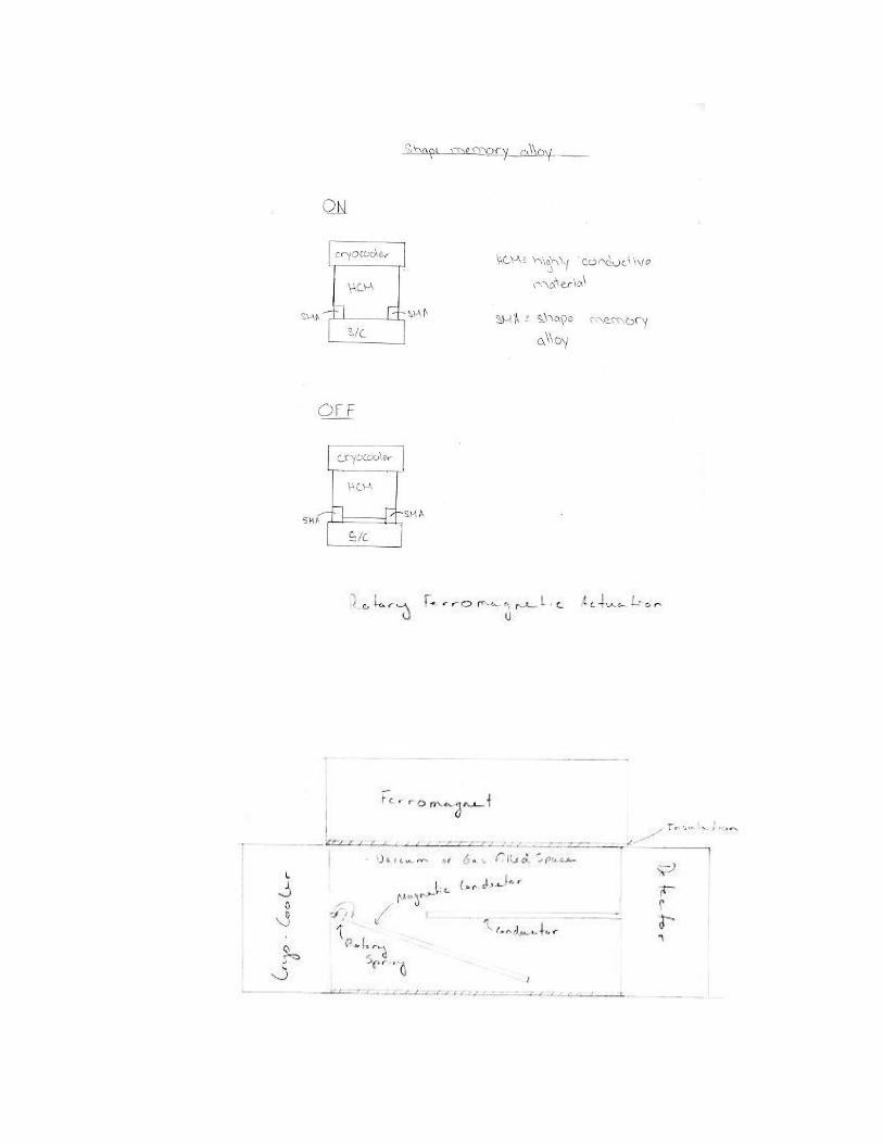
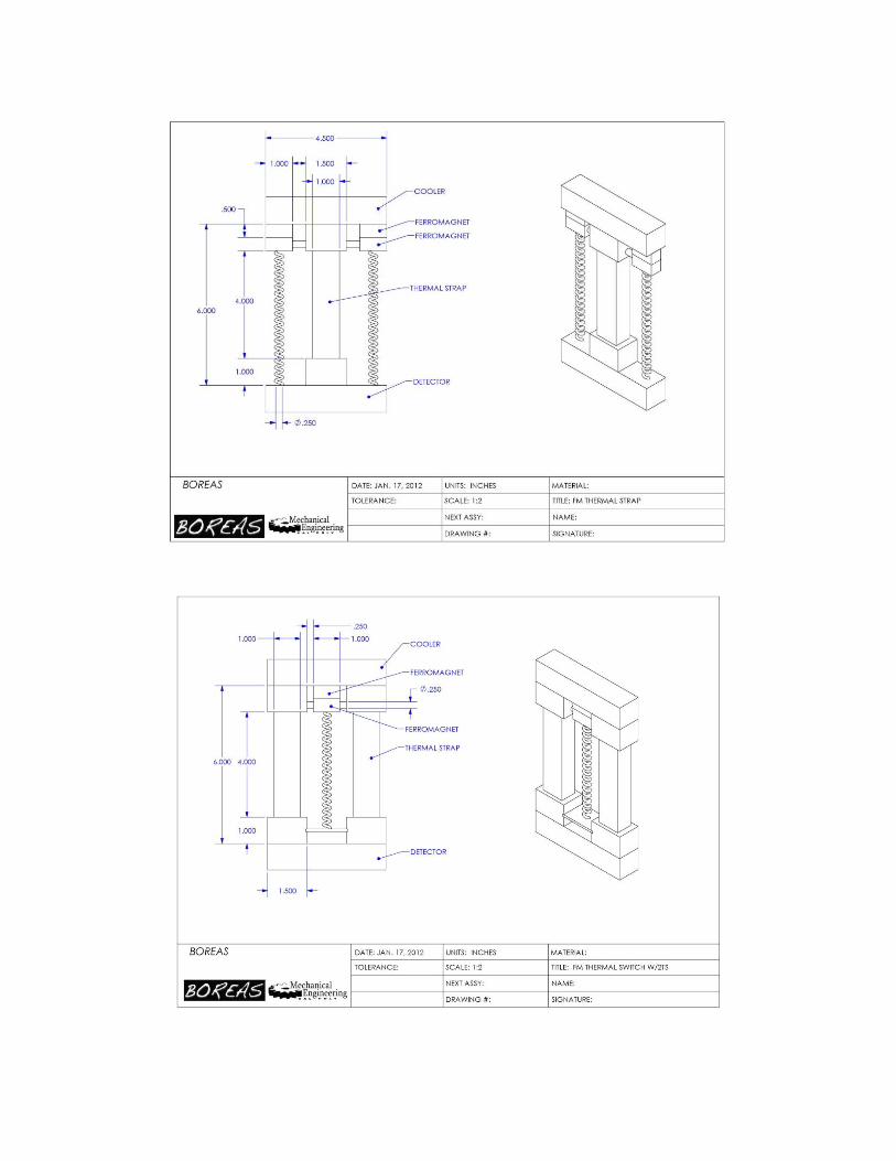
The first actuation method uses ferromagnets to actuate the switch “ON” and “OFF”. As seen in figure 7
there are two magnets, two thermal straps, one highly conductive material (HCM), and one spring
assembly. In the “ON” state, the cryocooler keeps the top magnet cool increasing the strength of its
magnetic field bringing the magnets into contact and subsequently stretching the spring. As the cooler
heats up, it will also heat up the magnet weakening its force. The spring force will overpower the
magnetic force as the magnetic force weakens thermally, delinking the thermal straps from the cooler.
The HCM helps keep an even pressure through the full contact area and helps stabilize the heat switch.
Figure 7. Draft model of ferromagnet heat switch.
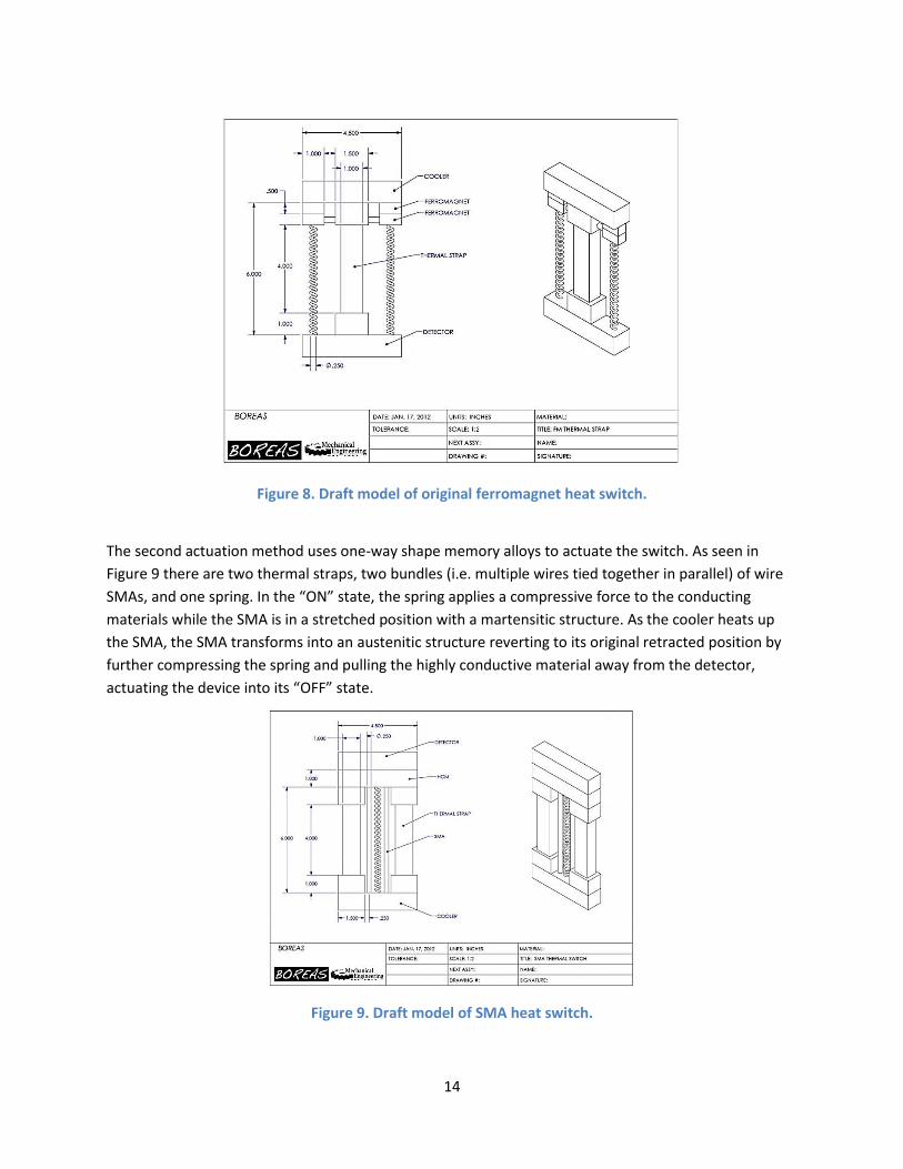
In the original design of the ferromagnet actuation (See Figure 8), there was only one thermal strap but
four magnets. This design presented itself with stability issues and it was redesigned for better stability
as shown in Figure 7.
14
Figure 8. Draft model of original ferromagnet heat switch.
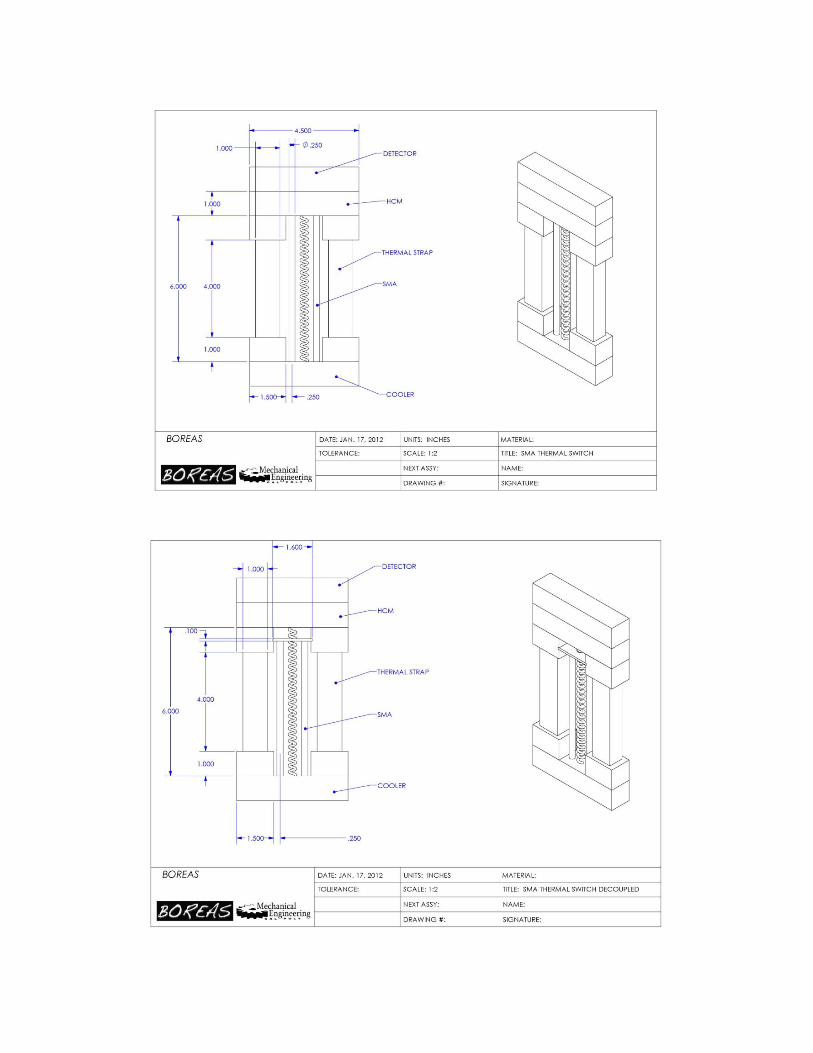
The second actuation method uses one-way shape memory alloys to actuate the switch. As seen in
Figure 9 there are two thermal straps, two bundles (i.e. multiple wires tied together in parallel) of wire
SMAs, and one spring. In the “ON” state, the spring applies a compressive force to the conducting
materials while the SMA is in a stretched position with a martensitic structure. As the cooler heats up
the SMA, the SMA transforms into an austenitic structure reverting to its original retracted position by
further compressing the spring and pulling the highly conductive material away from the detector,
actuating the device into its “OFF” state.
Figure 9. Draft model of SMA heat switch.
15
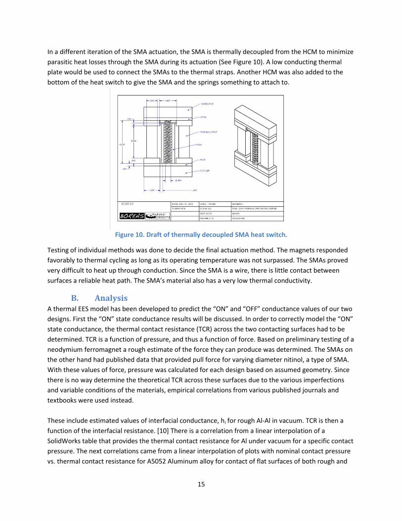
In a different iteration of the SMA actuation, the SMA is thermally decoupled from the HCM to minimize
parasitic heat losses through the SMA during its actuation (See Figure 10). A low conducting thermal
plate would be used to connect the SMAs to the thermal straps. Another HCM was also added to the
bottom of the heat switch to give the SMA and the springs something to attach to.
Figure 10. Draft of thermally decoupled SMA heat switch.
Testing of individual methods was done to decide the final actuation method. The magnets responded
favorably to thermal cycling as long as its operating temperature was not surpassed. The SMAs proved
very difficult to heat up through conduction. Since the SMA is a wire, there is little contact between
surfaces a reliable heat path. The SMA’s material also has a very low thermal conductivity.
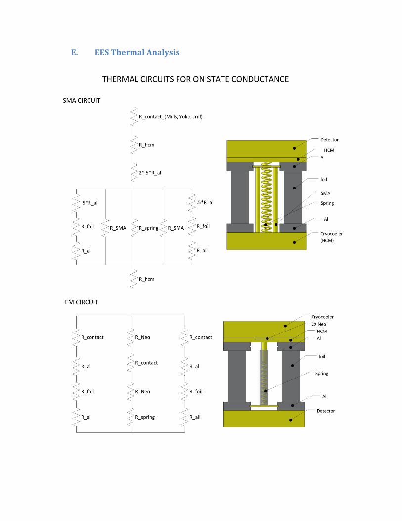
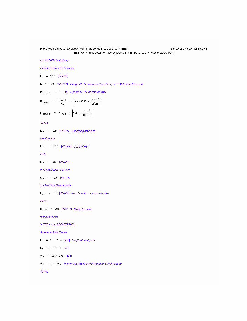
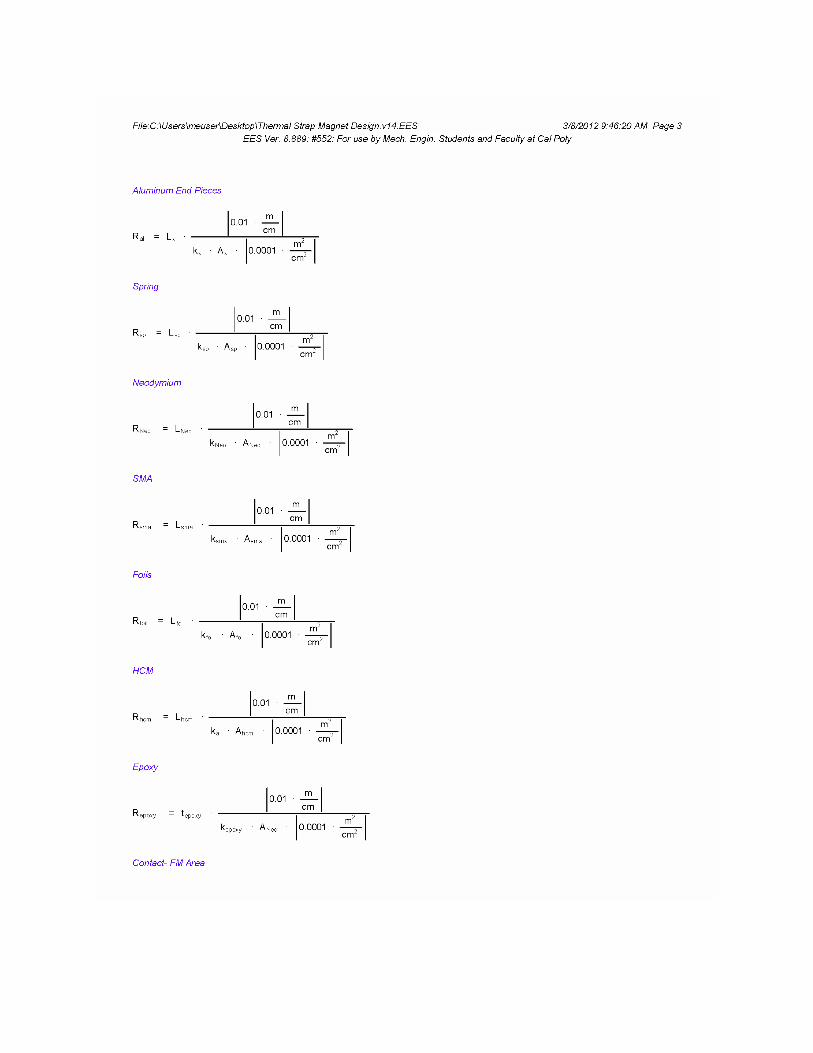
B. Analysis A thermal EES model has been developed to predict the “ON” and “OFF” conductance values of our two
designs. First the “ON” state conductance results will be discussed. In order to correctly model the “ON”
state conductance, the thermal contact resistance (TCR) across the two contacting surfaces had to be
determined. TCR is a function of pressure, and thus a function of force. Based on preliminary testing of a
neodymium ferromagnet a rough estimate of the force they can produce was determined. The SMAs on
the other hand had published data that provided pull force for varying diameter nitinol, a type of SMA.
With these values of force, pressure was calculated for each design based on assumed geometry. Since
there is no way determine the theoretical TCR across these surfaces due to the various imperfections
and variable conditions of the materials, empirical correlations from various published journals and
textbooks were used instead.
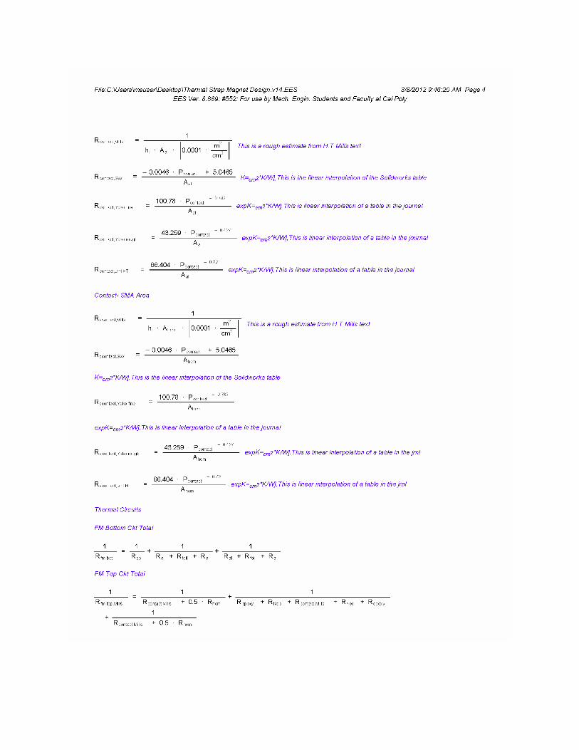
These include estimated values of interfacial conductance, hi for rough Al-Al in vacuum. TCR is then a
function of the interfacial resistance. [10] There is a correlation from a linear interpolation of a
SolidWorks table that provides the thermal contact resistance for Al under vacuum for a specific contact
pressure. The next correlations came from a linear interpolation of plots with nominal contact pressure
vs. thermal contact resistance for A5052 Aluminum alloy for contact of flat surfaces of both rough and
16
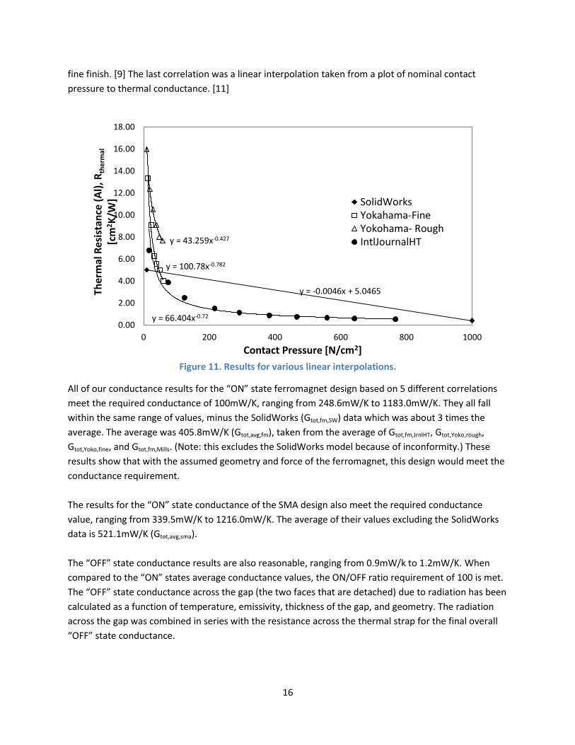
fine finish. [9] The last correlation was a linear interpolation taken from a plot of nominal contact
pressure to thermal conductance. [11]
Figure 11. Results for various linear interpolations.
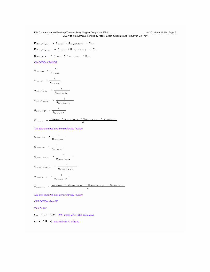
All of our conductance results for the “ON” state ferromagnet design based on 5 different correlations
meet the required conductance of 100mW/K, ranging from 248.6mW/K to 1183.0mW/K. They all fall
within the same range of values, minus the SolidWorks (Gtot,fm,SW) data which was about 3 times the
average. The average was 405.8mW/K (Gtot,avg,fm), taken from the average of Gtot,fm,JrnlHT, Gtot,Yoko,rough,
Gtot,Yoko,fine, and Gtot,fm,Mills. (Note: this excludes the SolidWorks model because of inconformity.) These
results show that with the assumed geometry and force of the ferromagnet, this design would meet the
conductance requirement.
The results for the “ON” state conductance of the SMA design also meet the required conductance
value, ranging from 339.5mW/K to 1216.0mW/K. The average of their values excluding the SolidWorks
data is 521.1mW/K (Gtot,avg,sma).
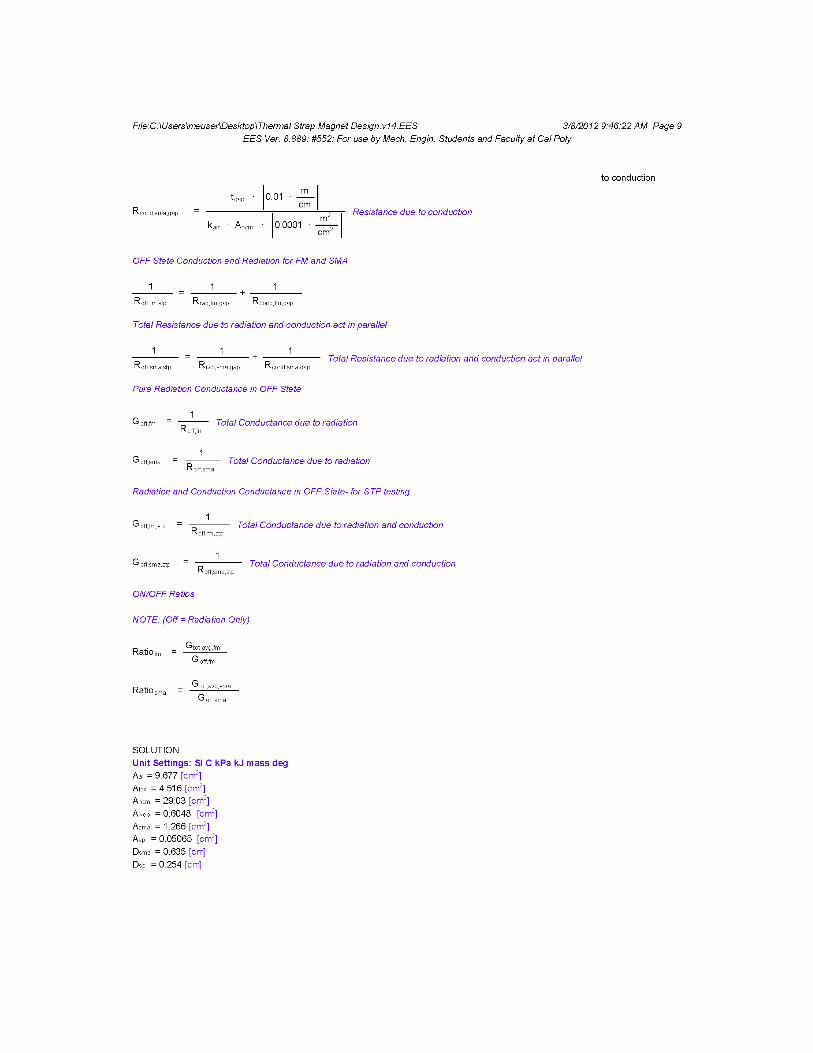
The “OFF” state conductance results are also reasonable, ranging from 0.9mW/k to 1.2mW/K. When
compared to the “ON” states average conductance values, the ON/OFF ratio requirement of 100 is met.
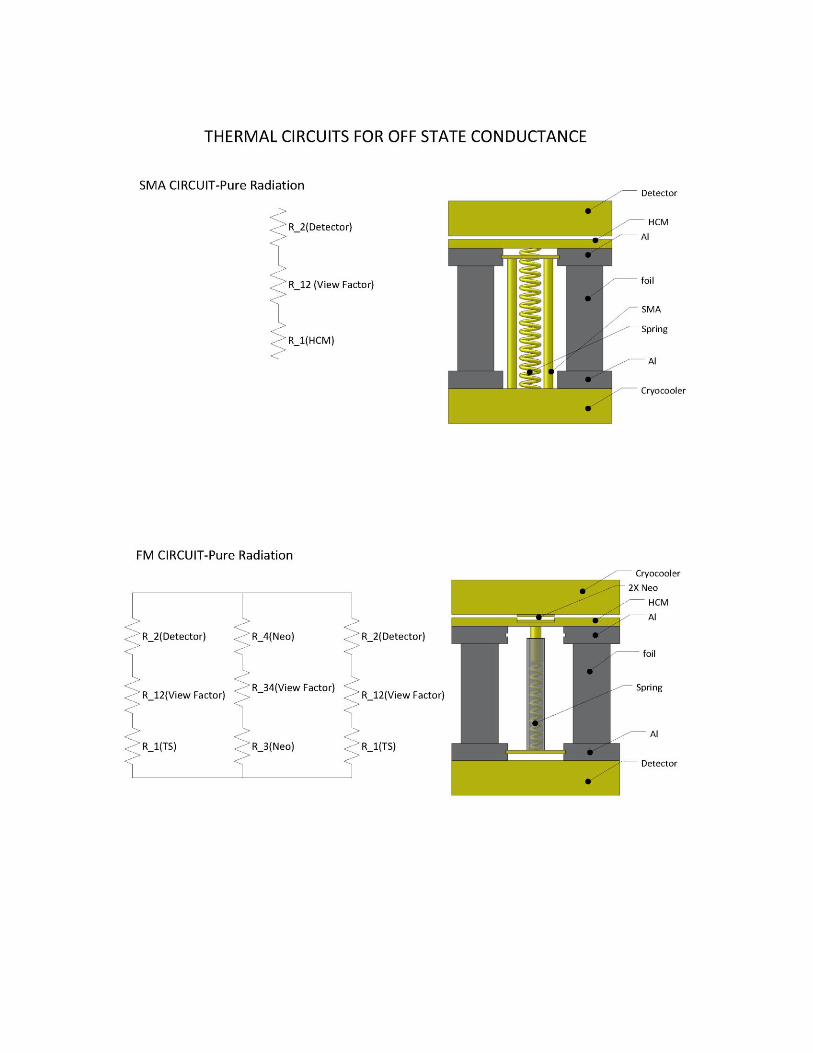
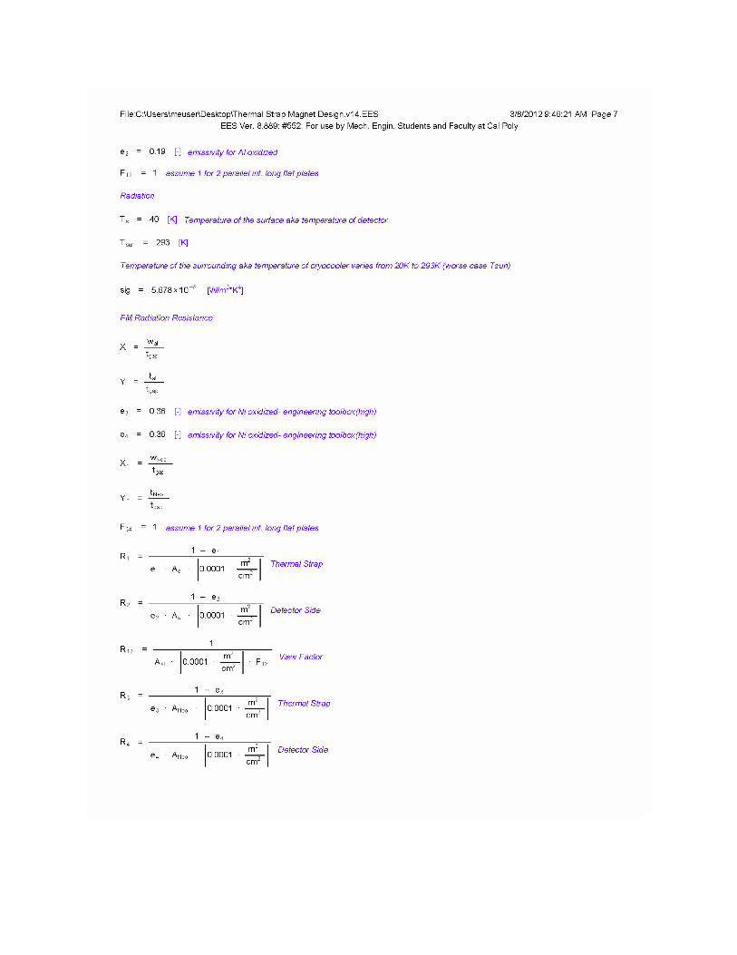
The “OFF” state conductance across the gap (the two faces that are detached) due to radiation has been
calculated as a function of temperature, emissivity, thickness of the gap, and geometry. The radiation
across the gap was combined in series with the resistance across the thermal strap for the final overall
“OFF” state conductance.
y = -0.0046x + 5.0465
y = 100.78x-0.782
y = 43.259x-0.427
y = 66.404x-0.72 0.00
2.00
4.00
6.00
8.00
10.00
12.00
14.00
16.00
18.00
0 200 400 600 800 1000
Ther
mal
Res
ista
nce
(A
l), R
the
rmal
[c
m2K
/W]
Contact Pressure [N/cm2]
SolidWorksYokahama-FineYokohama- RoughIntlJournalHT
17
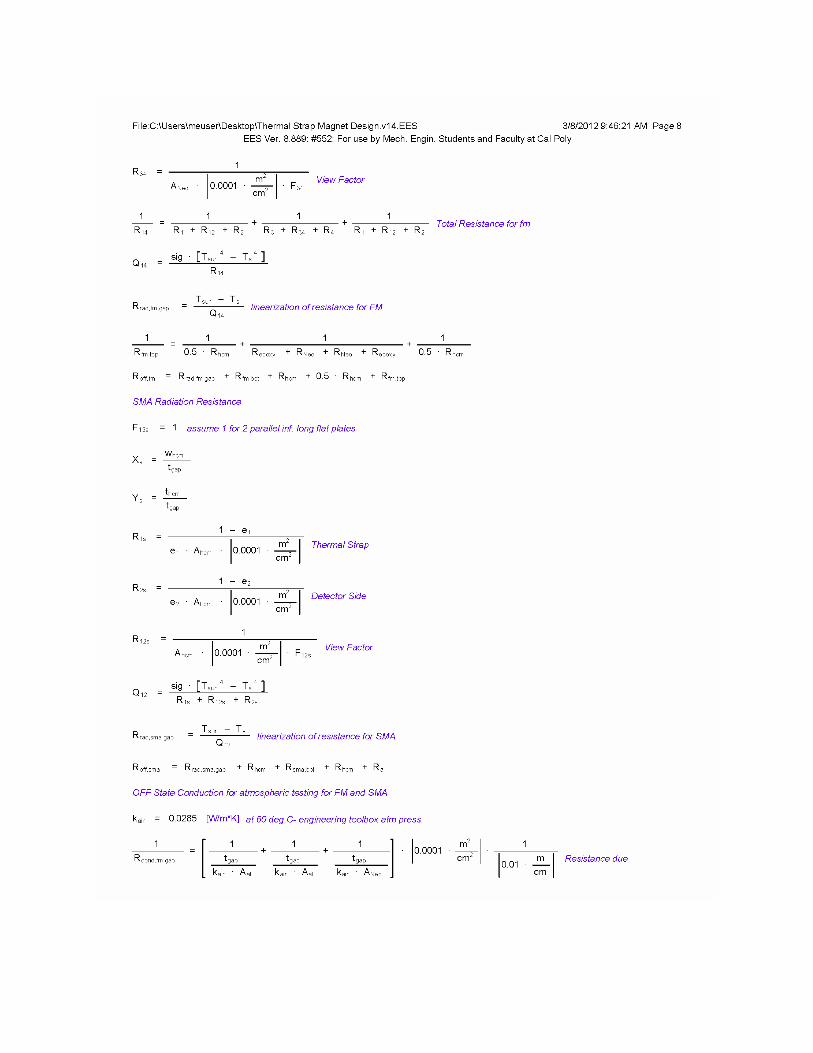
The group also determined the “OFF” state conductance for atmospheric testing which includes the
radiation and the conduction terms across the gap due to air at STP. The value of conductance due to
the conduction across the gap for the SMA is 3.86mW/K and for the ferromagnet is 34.7mW/K.
Ferromagnets and SMAs were tested for actuation force and actuation temperature. Springs were
chosen in accordance to the desired actuation temperature and actuation force. Once springs were
chosen a stretched length was determined to pull the magnets apart at the desired temperature range.
Fine tuning was completed once the prototype was built to get the needed stretched length of the
spring. Analysis is available in appendix E.
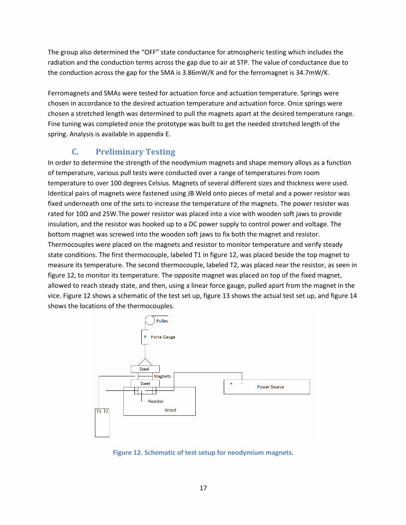
C. Preliminary Testing In order to determine the strength of the neodymium magnets and shape memory alloys as a function
of temperature, various pull tests were conducted over a range of temperatures from room
temperature to over 100 degrees Celsius. Magnets of several different sizes and thickness were used.
Identical pairs of magnets were fastened using JB Weld onto pieces of metal and a power resistor was
fixed underneath one of the sets to increase the temperature of the magnets. The power resister was
rated for 10Ω and 25W.The power resistor was placed into a vice with wooden soft jaws to provide
insulation, and the resistor was hooked up to a DC power supply to control power and voltage. The
bottom magnet was screwed into the wooden soft jaws to fix both the magnet and resistor.
Thermocouples were placed on the magnets and resistor to monitor temperature and verify steady
state conditions. The first thermocouple, labeled T1 in figure 12, was placed beside the top magnet to
measure its temperature. The second thermocouple, labeled T2, was placed near the resistor, as seen in
figure 12, to monitor its temperature. The opposite magnet was placed on top of the fixed magnet,
allowed to reach steady state, and then, using a linear force gauge, pulled apart from the magnet in the
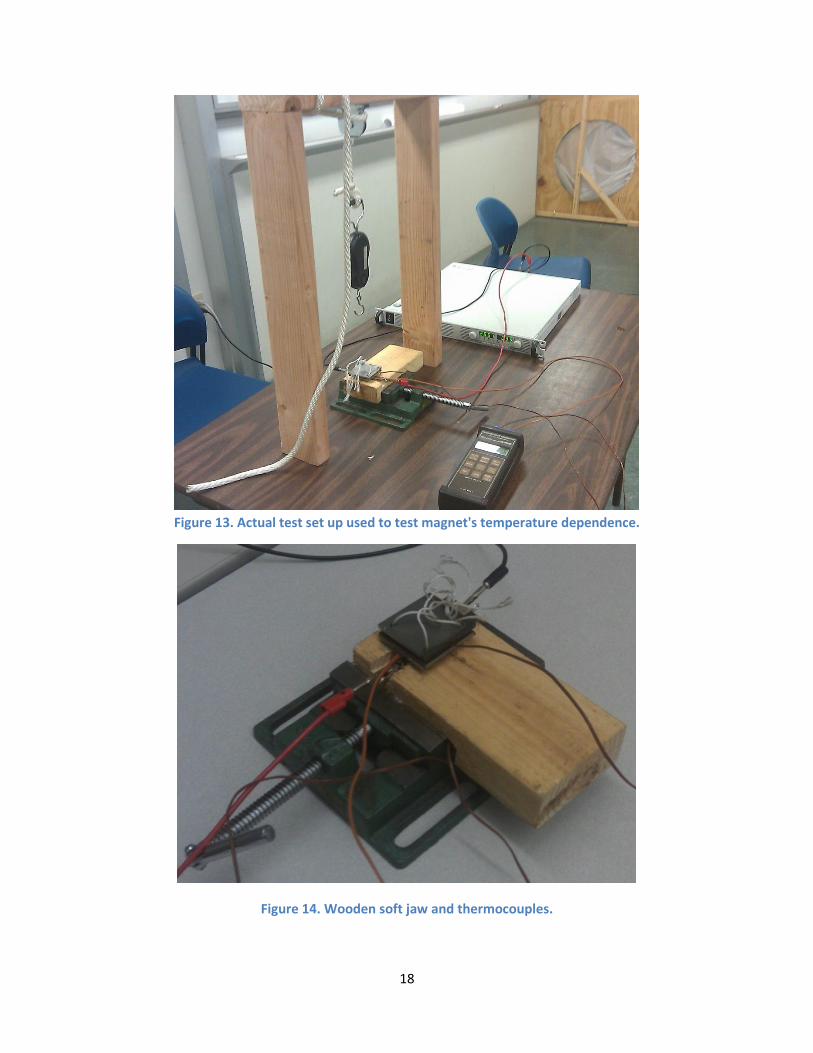
vice. Figure 12 shows a schematic of the test set up, figure 13 shows the actual test set up, and figure 14
shows the locations of the thermocouples.
Figure 12. Schematic of test setup for neodymium magnets.
18
Figure 13. Actual test set up used to test magnet's temperature dependence.
Figure 14. Wooden soft jaw and thermocouples.
19
Implementing a pulley allowed for more control over the rate of pull as well as keeping the direction of
force application constant. Temperature values were increased from roughly 10°C to 100°C in 20 degree
increments, with several readings of force data obtained at each temperature value.
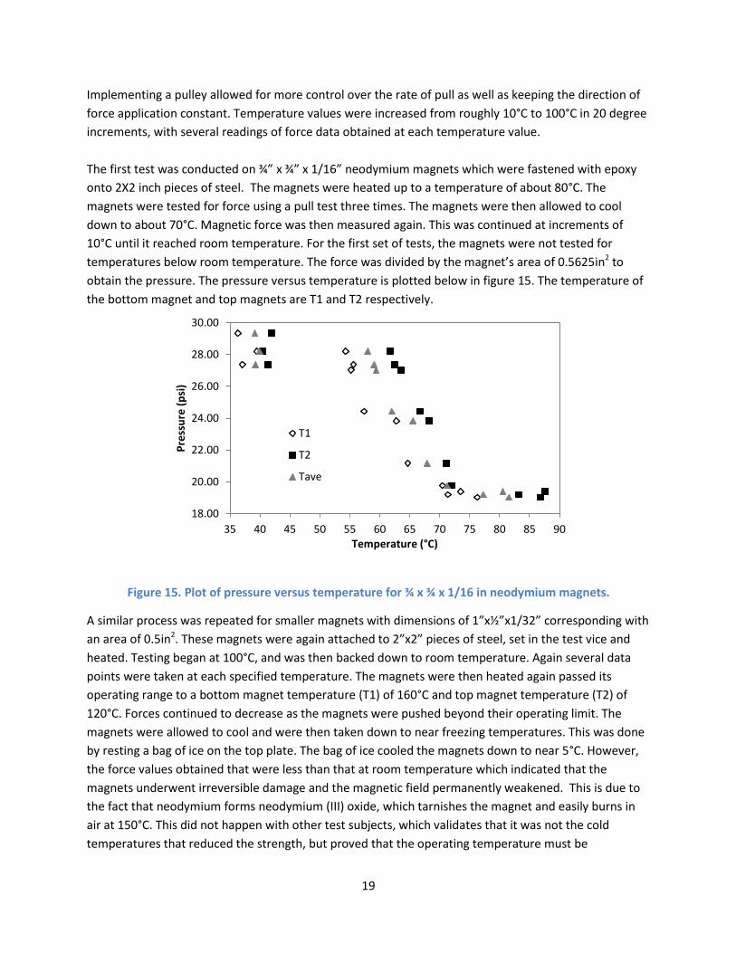
The first test was conducted on ¾” x ¾” x 1/16” neodymium magnets which were fastened with epoxy
onto 2X2 inch pieces of steel. The magnets were heated up to a temperature of about 80°C. The
magnets were tested for force using a pull test three times. The magnets were then allowed to cool
down to about 70°C. Magnetic force was then measured again. This was continued at increments of
10°C until it reached room temperature. For the first set of tests, the magnets were not tested for
temperatures below room temperature. The force was divided by the magnet’s area of 0.5625in2 to
obtain the pressure. The pressure versus temperature is plotted below in figure 15. The temperature of
the bottom magnet and top magnets are T1 and T2 respectively.
Figure 15. Plot of pressure versus temperature for ¾ x ¾ x 1/16 in neodymium magnets.
A similar process was repeated for smaller magnets with dimensions of 1”x½”x1/32” corresponding with
an area of 0.5in2. These magnets were again attached to 2”x2” pieces of steel, set in the test vice and
heated. Testing began at 100°C, and was then backed down to room temperature. Again several data
points were taken at each specified temperature. The magnets were then heated again passed its
operating range to a bottom magnet temperature (T1) of 160°C and top magnet temperature (T2) of
120°C. Forces continued to decrease as the magnets were pushed beyond their operating limit. The
magnets were allowed to cool and were then taken down to near freezing temperatures. This was done
by resting a bag of ice on the top plate. The bag of ice cooled the magnets down to near 5°C. However,
the force values obtained that were less than that at room temperature which indicated that the
magnets underwent irreversible damage and the magnetic field permanently weakened. This is due to
the fact that neodymium forms neodymium (III) oxide, which tarnishes the magnet and easily burns in
air at 150°C. This did not happen with other test subjects, which validates that it was not the cold
temperatures that reduced the strength, but proved that the operating temperature must be
18.00
20.00
22.00
24.00
26.00
28.00
30.00
35 40 45 50 55 60 65 70 75 80 85 90
Pre
ssu
re (
psi
)
Temperature (°C)
T1
T2
Tave
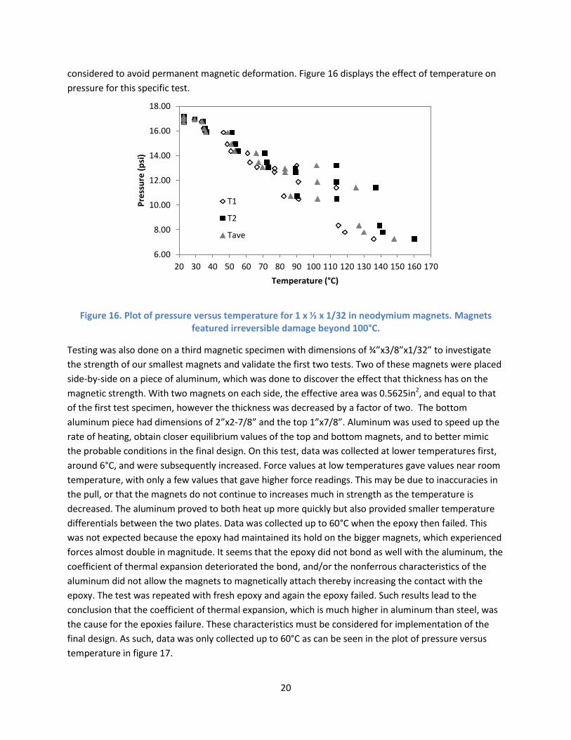
20
considered to avoid permanent magnetic deformation. Figure 16 displays the effect of temperature on
pressure for this specific test.
Figure 16. Plot of pressure versus temperature for 1 x ½ x 1/32 in neodymium magnets. Magnets featured irreversible damage beyond 100°C.
Testing was also done on a third magnetic specimen with dimensions of ¾”x3/8”x1/32” to investigate
the strength of our smallest magnets and validate the first two tests. Two of these magnets were placed
side-by-side on a piece of aluminum, which was done to discover the effect that thickness has on the
magnetic strength. With two magnets on each side, the effective area was 0.5625in2, and equal to that
of the first test specimen, however the thickness was decreased by a factor of two. The bottom
aluminum piece had dimensions of 2”x2-7/8” and the top 1”x7/8”. Aluminum was used to speed up the
rate of heating, obtain closer equilibrium values of the top and bottom magnets, and to better mimic
the probable conditions in the final design. On this test, data was collected at lower temperatures first,
around 6°C, and were subsequently increased. Force values at low temperatures gave values near room
temperature, with only a few values that gave higher force readings. This may be due to inaccuracies in
the pull, or that the magnets do not continue to increases much in strength as the temperature is
decreased. The aluminum proved to both heat up more quickly but also provided smaller temperature
differentials between the two plates. Data was collected up to 60°C when the epoxy then failed. This
was not expected because the epoxy had maintained its hold on the bigger magnets, which experienced
forces almost double in magnitude. It seems that the epoxy did not bond as well with the aluminum, the
coefficient of thermal expansion deteriorated the bond, and/or the nonferrous characteristics of the
aluminum did not allow the magnets to magnetically attach thereby increasing the contact with the
epoxy. The test was repeated with fresh epoxy and again the epoxy failed. Such results lead to the
conclusion that the coefficient of thermal expansion, which is much higher in aluminum than steel, was
the cause for the epoxies failure. These characteristics must be considered for implementation of the
final design. As such, data was only collected up to 60°C as can be seen in the plot of pressure versus
temperature in figure 17.
6.00
8.00
10.00
12.00
14.00
16.00
18.00
20 30 40 50 60 70 80 90 100 110 120 130 140 150 160 170
Pre
ssu
re (
psi
)
Temperature (°C)
T1
T2
Tave
21
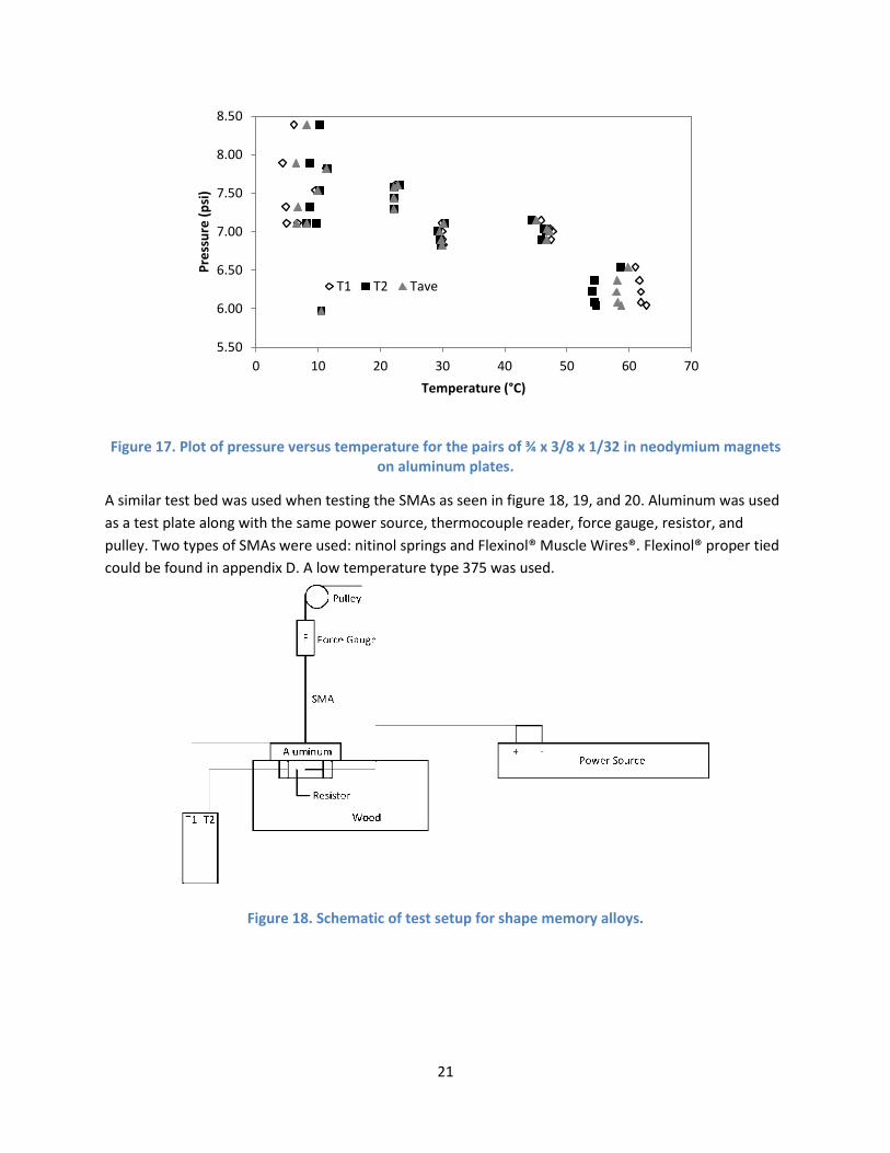
Figure 17. Plot of pressure versus temperature for the pairs of ¾ x 3/8 x 1/32 in neodymium magnets on aluminum plates.
A similar test bed was used when testing the SMAs as seen in figure 18, 19, and 20. Aluminum was used
as a test plate along with the same power source, thermocouple reader, force gauge, resistor, and
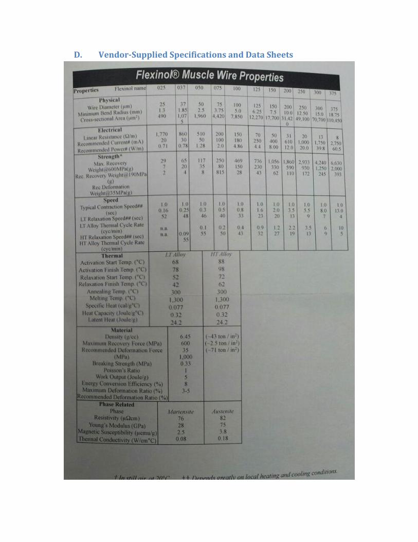
pulley. Two types of SMAs were used: nitinol springs and Flexinol® Muscle Wires®. Flexinol® proper tied
could be found in appendix D. A low temperature type 375 was used.
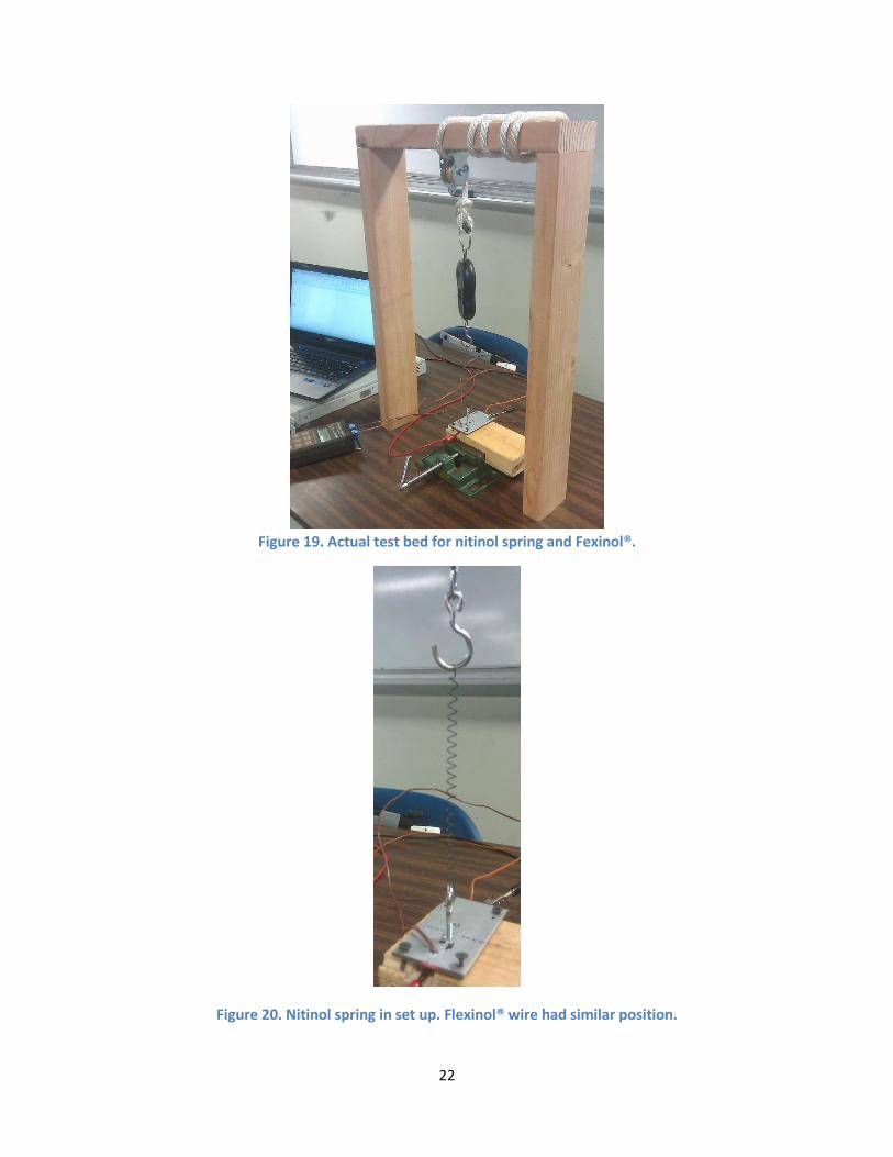
Figure 18. Schematic of test setup for shape memory alloys.
5.50
6.00
6.50
7.00
7.50
8.00
8.50
0 10 20 30 40 50 60 70
Pre
ssu
re (
psi
)
Temperature (°C)
T1 T2 Tave
22
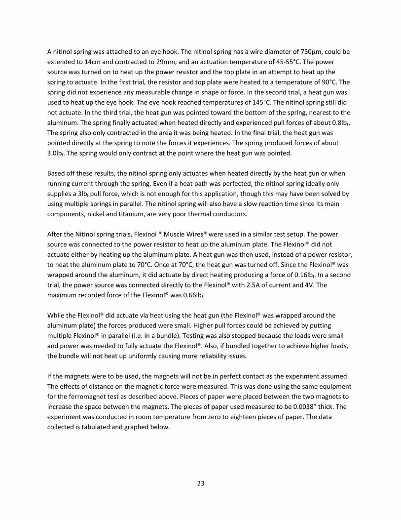
Figure 19. Actual test bed for nitinol spring and Fexinol®.
Figure 20. Nitinol spring in set up. Flexinol® wire had similar position.
23
A nitinol spring was attached to an eye hook. The nitinol spring has a wire diameter of 750µm, could be
extended to 14cm and contracted to 29mm, and an actuation temperature of 45-55°C. The power
source was turned on to heat up the power resistor and the top plate in an attempt to heat up the
spring to actuate. In the first trial, the resistor and top plate were heated to a temperature of 90°C. The
spring did not experience any measurable change in shape or force. In the second trial, a heat gun was
used to heat up the eye hook. The eye hook reached temperatures of 145°C. The nitinol spring still did
not actuate. In the third trial, the heat gun was pointed toward the bottom of the spring, nearest to the
aluminum. The spring finally actuated when heated directly and experienced pull forces of about 0.8lbf.
The spring also only contracted in the area it was being heated. In the final trial, the heat gun was
pointed directly at the spring to note the forces it experiences. The spring produced forces of about
3.0lbf. The spring would only contract at the point where the heat gun was pointed.
Based off these results, the nitinol spring only actuates when heated directly by the heat gun or when
running current through the spring. Even if a heat path was perfected, the nitinol spring ideally only
supplies a 3lbf pull force, which is not enough for this application, though this may have been solved by
using multiple springs in parallel. The nitinol spring will also have a slow reaction time since its main
components, nickel and titanium, are very poor thermal conductors.
After the Nitinol spring trials, Flexinol ® Muscle Wires® were used in a similar test setup. The power
source was connected to the power resistor to heat up the aluminum plate. The Flexinol® did not
actuate either by heating up the aluminum plate. A heat gun was then used, instead of a power resistor,
to heat the aluminum plate to 70°C. Once at 70°C, the heat gun was turned off. Since the Flexinol® was
wrapped around the aluminum, it did actuate by direct heating producing a force of 0.16lbf. In a second
trial, the power source was connected directly to the Flexinol® with 2.5A of current and 4V. The
maximum recorded force of the Flexinol® was 0.66lbf.
While the Flexinol® did actuate via heat using the heat gun (the Flexinol® was wrapped around the
aluminum plate) the forces produced were small. Higher pull forces could be achieved by putting
multiple Flexinol® in parallel (i.e. in a bundle). Testing was also stopped because the loads were small
and power was needed to fully actuate the Flexinol®. Also, if bundled together to achieve higher loads,
the bundle will not heat up uniformly causing more reliability issues.
If the magnets were to be used, the magnets will not be in perfect contact as the experiment assumed.
The effects of distance on the magnetic force were measured. This was done using the same equipment
for the ferromagnet test as described above. Pieces of paper were placed between the two magnets to
increase the space between the magnets. The pieces of paper used measured to be 0.0038” thick. The
experiment was conducted in room temperature from zero to eighteen pieces of paper. The data
collected is tabulated and graphed below.
24
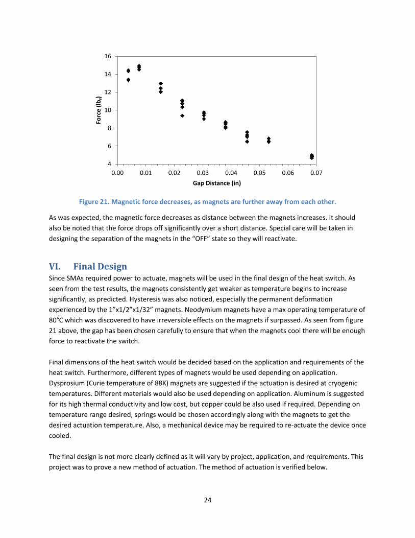
Figure 21. Magnetic force decreases, as magnets are further away from each other.
As was expected, the magnetic force decreases as distance between the magnets increases. It should
also be noted that the force drops off significantly over a short distance. Special care will be taken in
designing the separation of the magnets in the “OFF” state so they will reactivate.
VI. Final Design Since SMAs required power to actuate, magnets will be used in the final design of the heat switch. As
seen from the test results, the magnets consistently get weaker as temperature begins to increase
significantly, as predicted. Hysteresis was also noticed, especially the permanent deformation
experienced by the 1”x1/2”x1/32” magnets. Neodymium magnets have a max operating temperature of
80°C which was discovered to have irreversible effects on the magnets if surpassed. As seen from figure
21 above, the gap has been chosen carefully to ensure that when the magnets cool there will be enough
force to reactivate the switch.
Final dimensions of the heat switch would be decided based on the application and requirements of the
heat switch. Furthermore, different types of magnets would be used depending on application.
Dysprosium (Curie temperature of 88K) magnets are suggested if the actuation is desired at cryogenic
temperatures. Different materials would also be used depending on application. Aluminum is suggested
for its high thermal conductivity and low cost, but copper could be also used if required. Depending on
temperature range desired, springs would be chosen accordingly along with the magnets to get the
desired actuation temperature. Also, a mechanical device may be required to re-actuate the device once
cooled.
The final design is not more clearly defined as it will vary by project, application, and requirements. This
project was to prove a new method of actuation. The method of actuation is verified below.
4
6
8
10
12
14
16
0.00 0.01 0.02 0.03 0.04 0.05 0.06 0.07
Forc
e (
lbf)
Gap Distance (in)
25
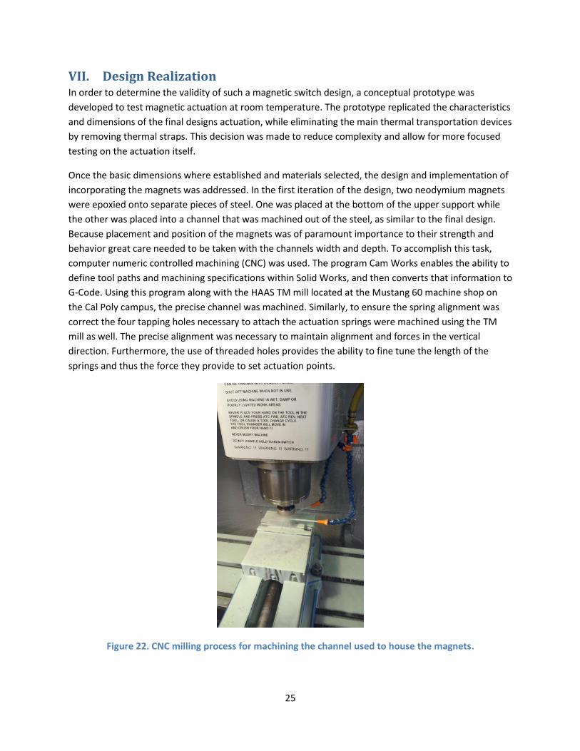
VII. Design Realization In order to determine the validity of such a magnetic switch design, a conceptual prototype was
developed to test magnetic actuation at room temperature. The prototype replicated the characteristics
and dimensions of the final designs actuation, while eliminating the main thermal transportation devices
by removing thermal straps. This decision was made to reduce complexity and allow for more focused
testing on the actuation itself.
Once the basic dimensions where established and materials selected, the design and implementation of
incorporating the magnets was addressed. In the first iteration of the design, two neodymium magnets
were epoxied onto separate pieces of steel. One was placed at the bottom of the upper support while
the other was placed into a channel that was machined out of the steel, as similar to the final design.
Because placement and position of the magnets was of paramount importance to their strength and
behavior great care needed to be taken with the channels width and depth. To accomplish this task,
computer numeric controlled machining (CNC) was used. The program Cam Works enables the ability to
define tool paths and machining specifications within Solid Works, and then converts that information to
G-Code. Using this program along with the HAAS TM mill located at the Mustang 60 machine shop on
the Cal Poly campus, the precise channel was machined. Similarly, to ensure the spring alignment was
correct the four tapping holes necessary to attach the actuation springs were machined using the TM
mill as well. The precise alignment was necessary to maintain alignment and forces in the vertical
direction. Furthermore, the use of threaded holes provides the ability to fine tune the length of the
springs and thus the force they provide to set actuation points.
Figure 22. CNC milling process for machining the channel used to house the magnets.
26
Upon assembly, it became evident that implementing the magnets with the channel design posed
several difficulties. Most noticeable was the fact that the magnets were attracted to the inside walls of
the channel which made it nearly impossible to maintain proper alignment while setting the epoxy.
Additionally, as the epoxy was laid on by hand, the height of each layer was difficult to control which
issued variability in the height thus affecting the on state gap distance between the magnets. This gap
distance is crucial to the design and has a pivotal role in the magnetic attraction as force decreases with
the square of the distance. For these reasons, this design was dropped for testing purposes and the
magnet was placed upon the top of the steel block instead. This does not as closely mimic the final
design, but for the purposes of validating a proof of concept, proved effective. This modification further
simplified the design by eliminating the gap distance in the “ON” state. The reduction of that variable
reduced the uncertainty and gave more direct control over the actuation.
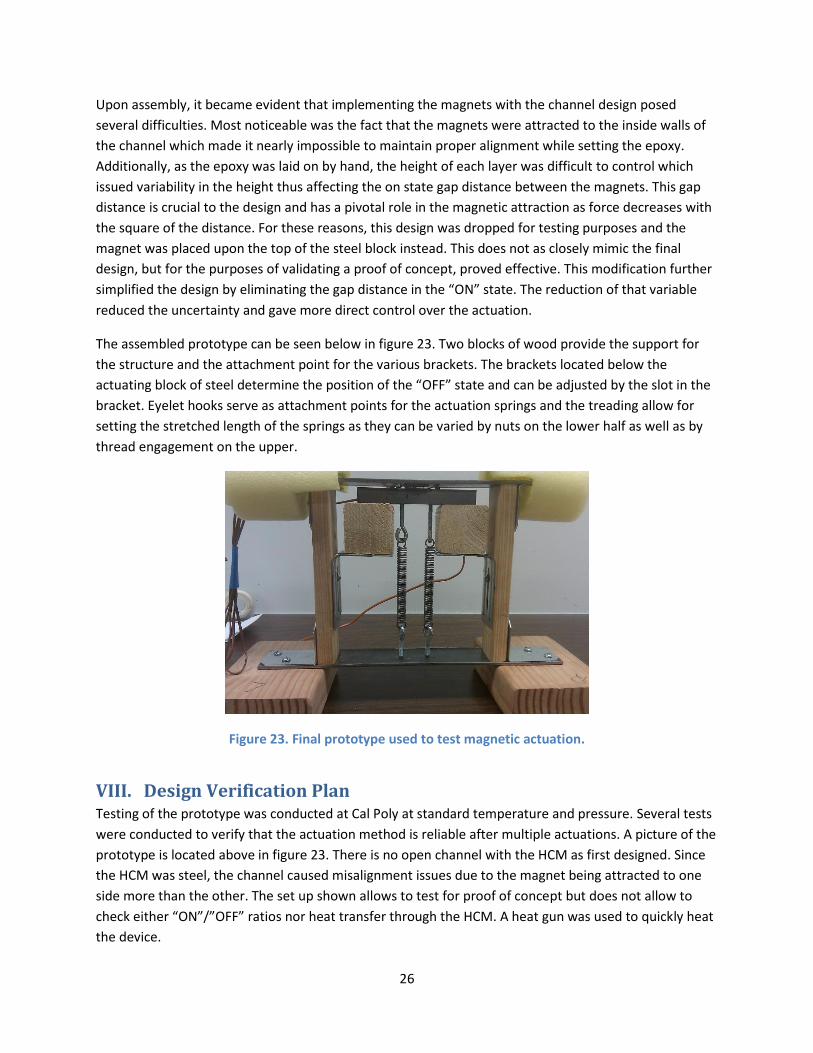
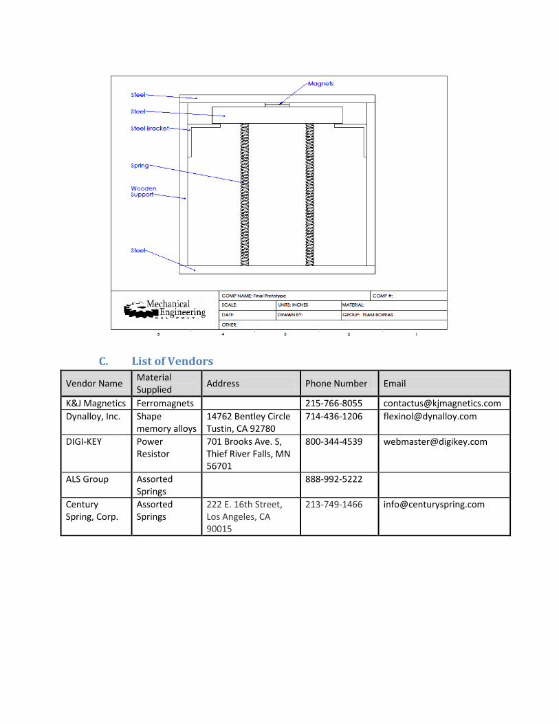
The assembled prototype can be seen below in figure 23. Two blocks of wood provide the support for
the structure and the attachment point for the various brackets. The brackets located below the
actuating block of steel determine the position of the “OFF” state and can be adjusted by the slot in the
bracket. Eyelet hooks serve as attachment points for the actuation springs and the treading allow for
setting the stretched length of the springs as they can be varied by nuts on the lower half as well as by
thread engagement on the upper.
Figure 23. Final prototype used to test magnetic actuation.
VIII. Design Verification Plan Testing of the prototype was conducted at Cal Poly at standard temperature and pressure. Several tests
were conducted to verify that the actuation method is reliable after multiple actuations. A picture of the
prototype is located above in figure 23. There is no open channel with the HCM as first designed. Since
the HCM was steel, the channel caused misalignment issues due to the magnet being attracted to one
side more than the other. The set up shown allows to test for proof of concept but does not allow to
check either “ON”/”OFF” ratios nor heat transfer through the HCM. A heat gun was used to quickly heat
the device.
27
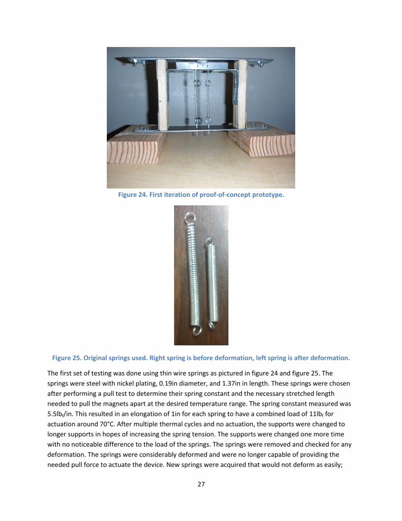
Figure 24. First iteration of proof-of-concept prototype.
Figure 25. Original springs used. Right spring is before deformation, left spring is after deformation.
The first set of testing was done using thin wire springs as pictured in figure 24 and figure 25. The
springs were steel with nickel plating, 0.19in diameter, and 1.37in in length. These springs were chosen
after performing a pull test to determine their spring constant and the necessary stretched length
needed to pull the magnets apart at the desired temperature range. The spring constant measured was
5.5lbf/in. This resulted in an elongation of 1in for each spring to have a combined load of 11lbf for
actuation around 70°C. After multiple thermal cycles and no actuation, the supports were changed to
longer supports in hopes of increasing the spring tension. The supports were changed one more time
with no noticeable difference to the load of the springs. The springs were removed and checked for any
deformation. The springs were considerably deformed and were no longer capable of providing the
needed pull force to actuate the device. New springs were acquired that would not deform as easily;
28
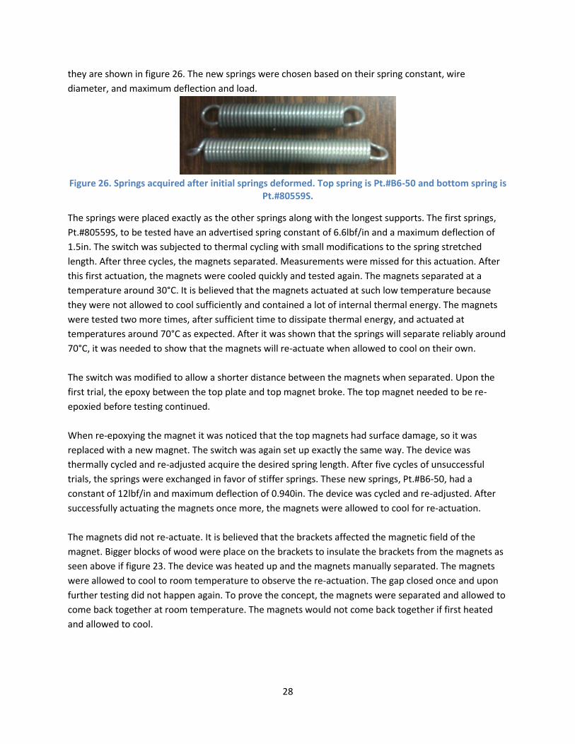
they are shown in figure 26. The new springs were chosen based on their spring constant, wire
diameter, and maximum deflection and load.
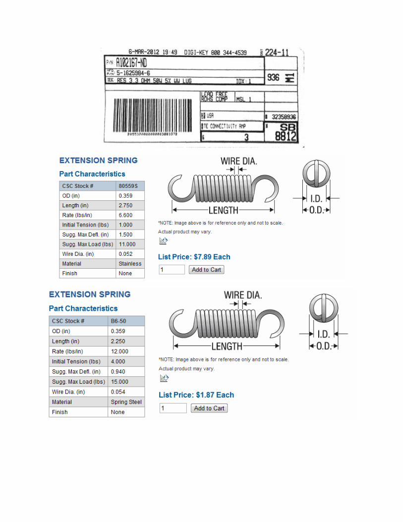
Figure 26. Springs acquired after initial springs deformed. Top spring is Pt.#B6-50 and bottom spring is
Pt.#80559S.
The springs were placed exactly as the other springs along with the longest supports. The first springs,
Pt.#80559S, to be tested have an advertised spring constant of 6.6lbf/in and a maximum deflection of
1.5in. The switch was subjected to thermal cycling with small modifications to the spring stretched
length. After three cycles, the magnets separated. Measurements were missed for this actuation. After
this first actuation, the magnets were cooled quickly and tested again. The magnets separated at a
temperature around 30°C. It is believed that the magnets actuated at such low temperature because
they were not allowed to cool sufficiently and contained a lot of internal thermal energy. The magnets
were tested two more times, after sufficient time to dissipate thermal energy, and actuated at
temperatures around 70°C as expected. After it was shown that the springs will separate reliably around
70°C, it was needed to show that the magnets will re-actuate when allowed to cool on their own.
The switch was modified to allow a shorter distance between the magnets when separated. Upon the
first trial, the epoxy between the top plate and top magnet broke. The top magnet needed to be re-
epoxied before testing continued.
When re-epoxying the magnet it was noticed that the top magnets had surface damage, so it was
replaced with a new magnet. The switch was again set up exactly the same way. The device was
thermally cycled and re-adjusted acquire the desired spring length. After five cycles of unsuccessful
trials, the springs were exchanged in favor of stiffer springs. These new springs, Pt.#B6-50, had a
constant of 12lbf/in and maximum deflection of 0.940in. The device was cycled and re-adjusted. After
successfully actuating the magnets once more, the magnets were allowed to cool for re-actuation.
The magnets did not re-actuate. It is believed that the brackets affected the magnetic field of the
magnet. Bigger blocks of wood were place on the brackets to insulate the brackets from the magnets as
seen above if figure 23. The device was heated up and the magnets manually separated. The magnets
were allowed to cool to room temperature to observe the re-actuation. The gap closed once and upon
further testing did not happen again. To prove the concept, the magnets were separated and allowed to
come back together at room temperature. The magnets would not come back together if first heated
and allowed to cool.
29
In order to separate the magnets when heated the magnets need to be a little stronger than when they
are cooled. The threshold between to allow separation at high temperatures and closing at low
temperatures is tiny. With the current equipment available, distances were not able to be set properly.
IX. Project Management Plan The first quarter of the project was dedicated to research of relevant material such as existing products
and novel materials. Design also started toward the end of the first quarter. Research was initially broad
reviewing existing designs and finding new and exciting materials. As the design process started,
research was narrowed to the information with more potential of developing a working prototype. At
the end of the quarter, ferromagnets and SMAs held the most promise. There was also an interest in
phase changing materials and gas conduction.
The second quarter consisted of refining the initial designs and completing the EES thermal analysis.
Further research was conducted into the actual materials that would be used in the prototype and
modeling of the heat path through the heat switch. Preliminary testing also started to test feasibility of
the different actuation methods and materials to be used in the prototype. Neodymium magnets, nitinol
springs, and Flexinol® Muscle Wire® were tested. The magnets were tested by heated by using a power
resistor and a pull test to measure force. Both nitinol springs and Flexinol® needed power to actuate.
Using the data collected a final design was chosen by the end of the quarter.
During the final quarter, a prototype was manufactured and tested for proof of concept. Final
dimensions and fittings were decided before manufacturing started. The prototype was not a complete
final product and was used and tested for proof of concept. Preliminary testing showed that the chosen
actuation method is feasible and would make a good alternative to existing designs. Manufacturing had
its difficulties because of tight tolerances. The springs need to be able to pull with enough force to
separate the magnets at the desired temperature range but not too much that the magnetic force in the
gap cannot overcome the same pull force when cooled.
X. Conclusion After conducting and collecting experimental data for the two different actuation methods, SMAs and
ferromagnets, the decision was made to move forward with ferromagnets for use in the final design.
Magnets responded much better to the experimental tests, which lightly simulate the actual conditions
that will be experienced in the device, and provided more reliable data as well as consistency. The SMAs
did not react as well to the simulated condition, if at all, and failed to contract all but an extremely small
amount even with direct heating at one end using a heat gun. Heat transfer occurred extremely slowly
though the material which caused excruciatingly long actuation times as well as minimal contrition and
force production.
A conceptual prototype was developed to test the actuation abilities of neodymium magnets in a similar
orientation to that of the final design. Through multiple tests and various initial conditions, it was
30
proven that the reduction of magnetic force in the magnets is substantial enough to allow for actuation
from the “ON” to “OFF” states. This actuation was repeated several times at each of the two operating
conditions for which it occurred. Furthermore, at room temperature, when the magnets were manually
changed from the “ON” state they would return on their own for extremely small “OFF” state gap
distances. Returning the prototype to the “ON” state after heating however, posed several challenges
and ultimately only occurred once during testing. Initially, the complications arose from the slight
magnetic force between the brackets and actuating magnet. Although small pieces of wood lay in
between the attraction was enough to restrict the magnets from reengaging. In order to mitigate this
effect, larger pieces of wood were placed on top of the magnets. With this configuration, magnetic
actuation back to the “ON” state did occur but was only proven once. Any slight nudge or movement
would however, return the system from the “OFF” state to the “ON” state. Hence, the system was on
the cusp between the two equilibrium points of the bi-stable system.
These results have proven that passive actuation using the temperature dependent magnetic properties
of magnets is plausible for heat switch design. Although the results did not prove as repeatable as was
expected, several factors and variations would allow for greater consistency when applied to a specific
design. The gap distance between the magnets in the “OFF” state was the prominent variable and was
extremely difficult to control given the capabilities of the prototype. Implementing brackets, which can
be simultaneously adjusted, to provide the correct spacing to a high precision, such as by micrometers,
would allow for the fine tuning necessary to establish the distances need for the bi-stable conditions of
the system. Furthermore, higher strength mounting components and brackets would reduce the effects
of deflection in the “OFF” state, maintaining the tight dimensions required. Additionally, the right spring
force was highly important for obtaining actuation. Although the prototype did allow for slight
adjustments of the spring length through the threaded attachments, providing for a more accurate way
to adjust the stretched length along with more controllable gap distances would allow for far greater
repeatability. When heating the magnets, applying a methodical heat source such as resistors, may also
increase repeatability. Slower heat transfer rates would allow for heat dissipation to occur in a more
uniform manner through the magnets, thus providing smaller temperature differences between them.
As such, the magnetic fields would weaken at similar rates giving more stable and predictable actuation
times.
When applying magnetic actuation to a cryogenic thermal switch several more recommendations should
be noted. Steel was used in the prototype due to its availability and cost, but the complications due to
the magnetic effects proved a challenge. Materials which do not exhibit these behaviors would serve far
more reliable and mitigate any undesired magnetic effects. It should also be noted that the difference
between the coefficient of thermal expansion of the magnets and material that it lays should be similar
due to the range of temperature exposure. A mismatch could cause cracking or failure of the bonding
agent which was seen in our tests when aluminum was used or the steel was heated very rapidly. Bi-
metallic fixtures would prove another plausible remedy for this challenge. With regards to bonding
itself, an agent proven at the desire temperature range is paramount. Epoxy failure compromises the
performance of the entire system and cannot be easily remedied. Furthermore, implementing an epoxy
with repeatable application thickness provides tighter control over the dimensions and subsequently the
31
gap distances. Machining and holding tighter tolerances and clearances is necessary for an actuation
method as sensitive as this. Because the slightest variation could cause the system to fail to actuate,
maintaining tolerances of only a few thousands of an inch is needed. Various types of magnets may be
selected depending on the temperature range of the desired actuation. Testing was completed at
atmospheric conditions, therefore neodymium magnets were used. For lower temperature in the
cryogenic regime, magnets such as dysprosium and gadolinium should be considered. Further testing to
determine the strength of their magnetic fields would need to be first conducted, and then a design
point may be subsequently fashioned. Finally, investigating the possibility of adding a mechanical device
to return the system from the “OFF” to “ON” states should considered. The slightest disturbance would
provoke the system to return to the “ON” state, and through the use of temperature or remote control,
the heat switch could be reengaged by an active system. Such a system may be considered if only for a
failsafe situation.
Implementing magnets for use in cryogenic heat switches holds promise. Much research still needs to be
conducted especially at those low temperatures to determine the magnetic force as a function of
temperature. Once that information is obtained, specific design points can be established and
consequently a unique design for a specific application.
With regards to the thermal requirements of the system, the model simulation carried out with EES
demonstrates the designs fulfillment and potential. Using data obtained from experimental testing and
geometries congruent with the prototype, conductance in the “ON” and “OFF” states was well as
conductance ratios surpassed the required values. Since testing was only carried out to prove whether
or not the actuation method was plausible, further thermal testing for a specific design catered to its
particular application should also be completed. Preliminary computational analysis through thermal
modeling for those specific geometries needs to be conducted prior to physical testing. Subsequently,
the physic model developed from those results may be examined to obtain actual conductance values
and ratios. Due to the small gap distances necessary to complete actuation to and from the “ON” to
“OFF” states, radiative heat transfer in the “OFF” state may indeed prove a significant means of heat
transfer and thus reduce the “OFF” state conductance as well as conductance ratio. Nevertheless,
depending on the specific application and design criteria, a small increase in “OFF” state conduction may
not hinder or compromise the heat switch. Furthermore, vacuum chamber testing may be required for
certain applications in space environments.
Implementing magnets for use in cryogenic heat switches holds promise. Much research still needs to be
conducted, especially at low temperatures in the cryogenic regime to determine the magnetic force as a
function of temperature. Once that information is obtained, specific design points can be established
and consequently a unique design for a specific application. Similarly, thermal data must be obtained to
evaluate the overall performance of a heat switch in addition to its actuation capabilities. With further
research, magnetic heat switches may provide a reliable alternative to the current methods available.
32
XI. References 1. Cryogenics, written by Michael McClintock, Reinhold Publishing Cooperation, 1964.
2. Heat Transfer at Low Temperatures, edited by Walter Frost, Plenum Press, New York and
London, 1975.
3. Takashi Mineta, Yoichi Haga: Materials and Processes in Shape Memory Alloy, Graduate School
of Science and Engineering, Yamagata University, Yonezawa, Japan (2011)
4. O. Haglund: Curie Temperature of Alloys, its Measurement and Technical Importance, Journal of
Thermal Analysis, Vol. 25 (1982) 21-43
5. M. Prina, P. Bhandari, R. C. Bowman Jr., C. G. Paine, L. A. Wade: Development of Gas Gap
Heat Switch Actuator for the Planck Sorption Cryocooler, Jet Propulsion Laboratory,
Pasadena, CA, Politecnico di Milano, Milano, Italy
6. Material Properties: G-10 CR (Fiberglass Epoxy), National Institute of Standards and Technology,
7. Binneberg A, Kaiser G, inventors; Oct. 23, 2001. Self-triggering cryogenic heat flow switch.
United States patent US 6305174 B1
8. Stuart R, Hogan W, inventors; Mar. 4, 1969. Thermal Switch for Cryogenic Apparatus. United
States patent US 3430455
9. Koichi Nishino, Shigemasa Yamashita, Kahoru Torii, Thermal contact conductance under low
applied load in a vacuum environment, Experimental Thermal and Fluid Science, Volume 10,
Issue 2, February 1995, Pages 258-271, ISSN 0894-1777, 10.1016/0894-1777(94)00091-L.
(http://www.sciencedirect.com/science/article/pii/089417779400091L)
10. Mills, Anthony F. Heat Transfer. Upper Saddle River, NJ: Prentice Hall, 1999. Print.
11. T. McWaid, E. Marshall, Thermal contact resistance across pressed metal contacts in a vacuum
environment, International Journal of Heat and Mass Transfer, Volume 35, Issue 11, November
1992, Pages 2911-2920, ISSN 0017-9310, 10.1016/0017-9310(92)90311-F.
(http://www.sciencedirect.com/science/article/pii/001793109290311F)

XII. Appendices
A. Morphological Attributes List

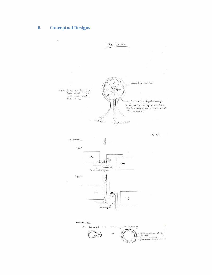
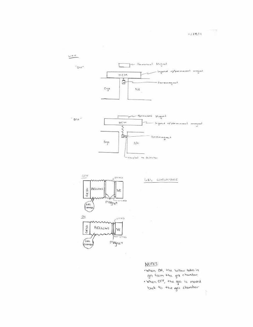
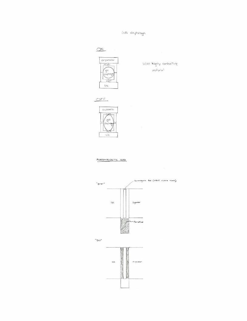
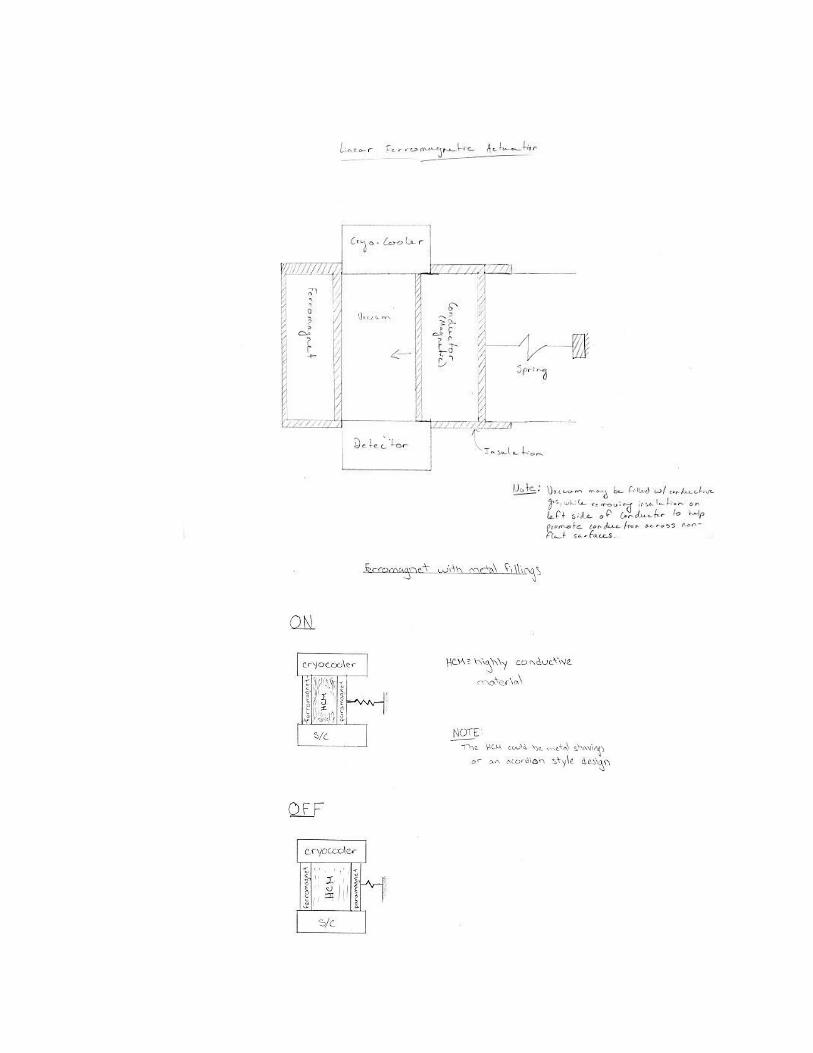
B. Conceptual Designs

C. List of Vendors
Vendor Name Material Supplied
Address Phone Number Email
K&J Magnetics Ferromagnets 215-766-8055 [email protected]
Dynalloy, Inc. Shape memory alloys
14762 Bentley Circle Tustin, CA 92780
714-436-1206 [email protected]
DIGI-KEY Power Resistor
701 Brooks Ave. S, Thief River Falls, MN 56701
800-344-4539 [email protected]
ALS Group Assorted Springs
888-992-5222
Century Spring, Corp.
Assorted Springs
222 E. 16th Street, Los Angeles, CA 90015
213-749-1466 [email protected]
D. Vendor-Supplied Specifications and Data Sheets
E. EES Thermal Analysis


F. Gantt Chart


G. Test Equipment
Equipment Brand Model #
Power Source Agilent Technologies N5747A
Thermocouple Reader OMEGA® HH23
Force Gauge Cen-Tech® 97227
Heat Gun Masterflow® AH-501
XIII. Acknowledgements Eugenio Urquiza, Jet Propulsion Laboratory mentor
Jose I. Rodriguez, Jet Propulsion Laboratory advisor
Paige Lewis, Cryoquip technical advisor - discussed cryogenics and properties of gases
Mohammad Noori, Senior project advisor