Embed Size (px)
Citation preview
Crystal Inc.Crystal Inc. CS8900A-ISA Ethernet CS8900A-ISA Ethernet
ControllerController
Presented byPresented by
Kallol ParKallol ParApril, 17 2003April, 17 2003
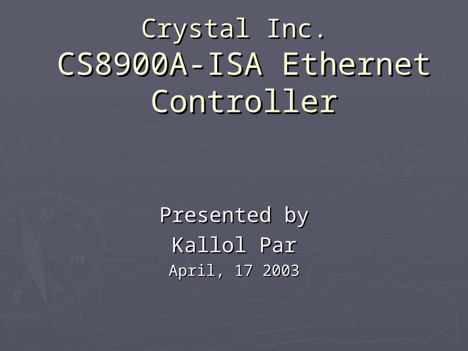
Key FeaturesKey Features► Low CostLow Cost
4K Integrated RAM4K Integrated RAM On-chip 10Base-T filters (so no On-chip 10Base-T filters (so no
filter/transformer packages)filter/transformer packages) Designed to fit on 2-layer circuit boardDesigned to fit on 2-layer circuit board Small PCB footprint - Thin Quad Flat Pack Small PCB footprint - Thin Quad Flat Pack
►High PerformanceHigh Performance Software selectable I/O, Memory mode for Software selectable I/O, Memory mode for
optimum performance through PacketPage™ optimum performance through PacketPage™ ArchitectureArchitecture
Early interrupts allow the host to preprocess Early interrupts allow the host to preprocess incoming framesincoming frames
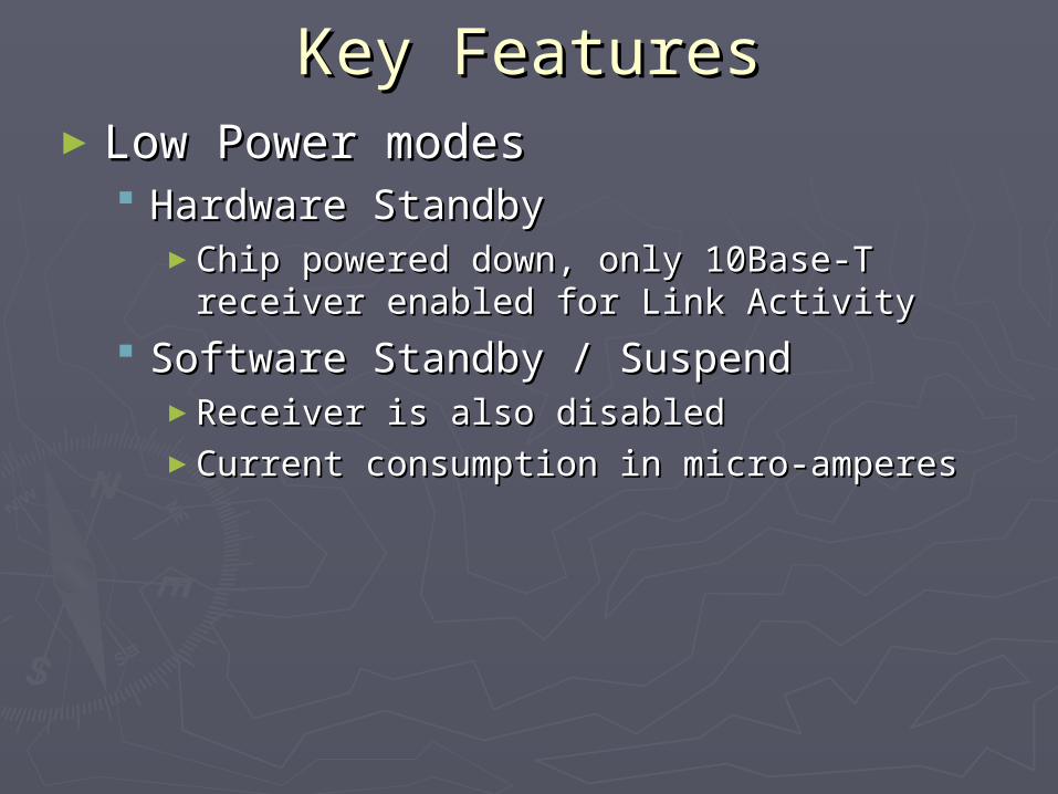
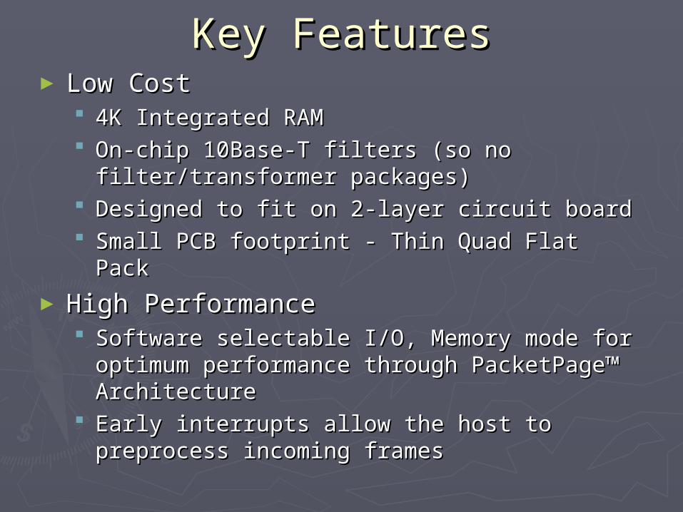
Key FeaturesKey Features►Low Power modesLow Power modes
Hardware StandbyHardware Standby►Chip powered down, only 10Base-T receiver Chip powered down, only 10Base-T receiver
enabled for Link Activityenabled for Link Activity
Software Standby / SuspendSoftware Standby / Suspend►Receiver is also disabled Receiver is also disabled ►Current consumption in micro-amperesCurrent consumption in micro-amperes

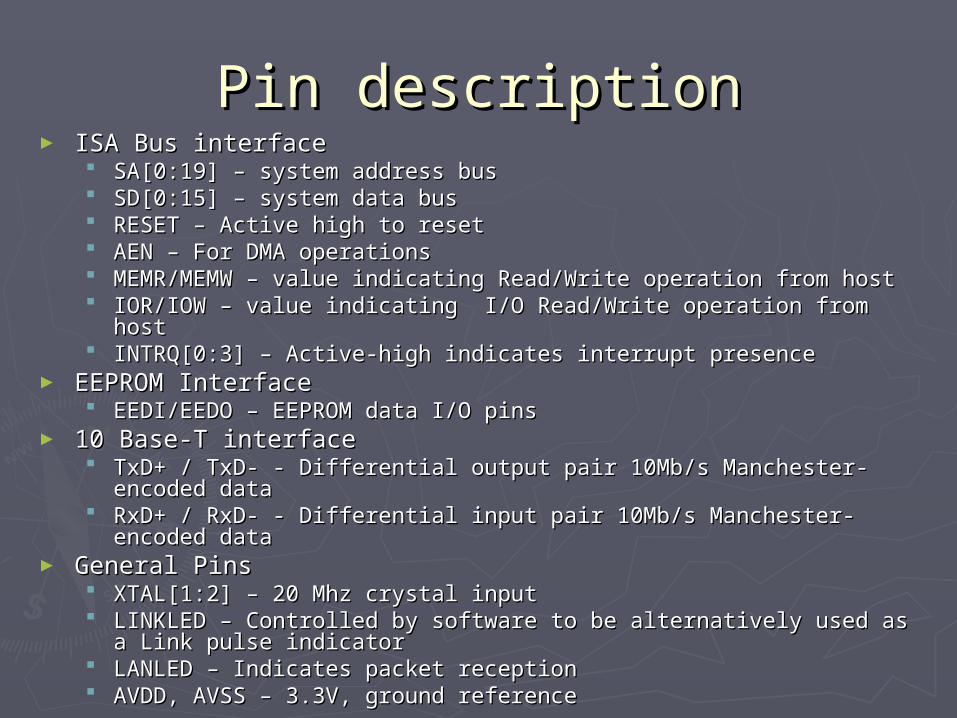
Pin descriptionPin description► ISA Bus interfaceISA Bus interface
SA[0:19] – system address busSA[0:19] – system address bus SD[0:15] – system data busSD[0:15] – system data bus RESET – Active high to resetRESET – Active high to reset AEN – For DMA operationsAEN – For DMA operations MEMR/MEMW – value indicating Read/Write operation from hostMEMR/MEMW – value indicating Read/Write operation from host IOR/IOW – value indicating I/O Read/Write operation from hostIOR/IOW – value indicating I/O Read/Write operation from host INTRQ[0:3] – Active-high indicates interrupt presenceINTRQ[0:3] – Active-high indicates interrupt presence
► EEPROM InterfaceEEPROM Interface EEDI/EEDO – EEPROM data I/O pinsEEDI/EEDO – EEPROM data I/O pins
► 10 Base-T interface10 Base-T interface TxD+ / TxD- - Differential output pair 10Mb/s Manchester-TxD+ / TxD- - Differential output pair 10Mb/s Manchester-
encoded dataencoded data RxD+ / RxD- - Differential input pair 10Mb/s Manchester-encoded RxD+ / RxD- - Differential input pair 10Mb/s Manchester-encoded
datadata► General PinsGeneral Pins
XTAL[1:2] – 20 Mhz crystal inputXTAL[1:2] – 20 Mhz crystal input LINKLED – Controlled by software to be alternatively used as a LINKLED – Controlled by software to be alternatively used as a
Link pulse indicatorLink pulse indicator LANLED – Indicates packet receptionLANLED – Indicates packet reception AVDD, AVSS – 3.3V, ground referenceAVDD, AVSS – 3.3V, ground reference
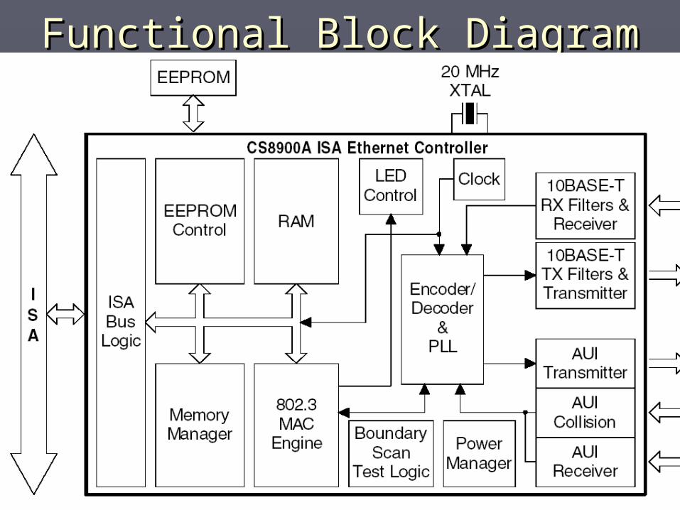
Functional Block DiagramFunctional Block Diagram
PacketPage ArchitecturePacketPage Architecture
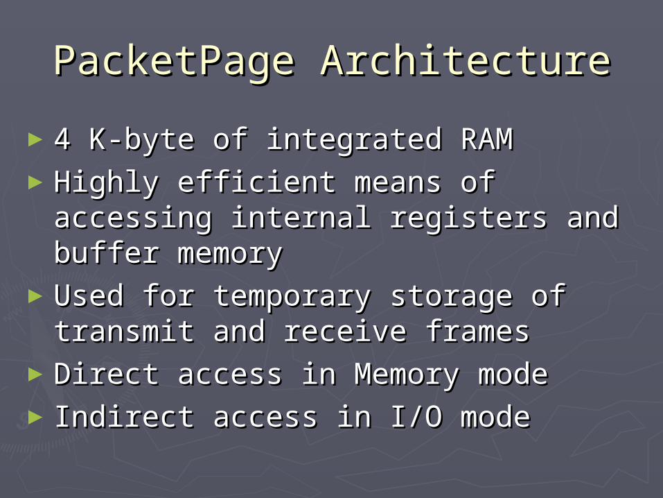
►4 K-byte of integrated RAM4 K-byte of integrated RAM►Highly efficient means of accessing Highly efficient means of accessing
internal registers and buffer memoryinternal registers and buffer memory►Used for temporary storage of transmit Used for temporary storage of transmit
and receive framesand receive frames►Direct access in Memory mode Direct access in Memory mode ► Indirect access in I/O modeIndirect access in I/O mode
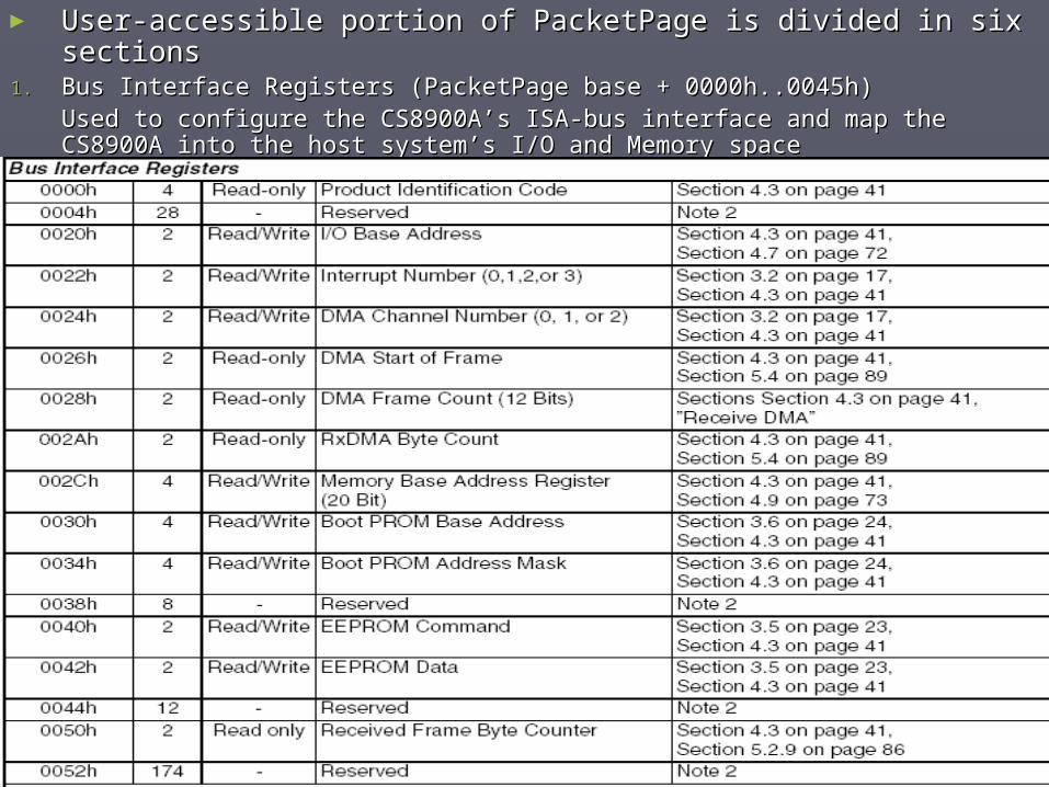
► User-accessible portion of PacketPage is divided in six sections User-accessible portion of PacketPage is divided in six sections 1.1. Bus Interface Registers (PacketPage base + 0000h..0045h)Bus Interface Registers (PacketPage base + 0000h..0045h)
Used to configure the CS8900A’s ISA-bus interface and map the CS8900A Used to configure the CS8900A’s ISA-bus interface and map the CS8900A into the host system’s I/O and Memory spaceinto the host system’s I/O and Memory space
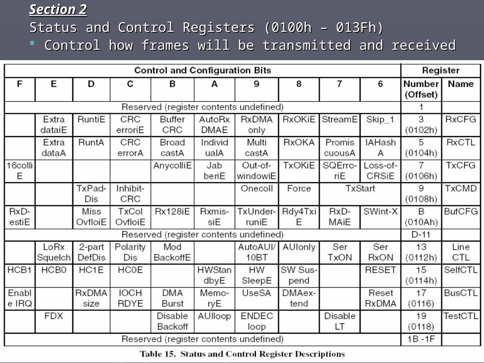
Section 2Section 2Status and Control Registers (0100h – 013Fh)Status and Control Registers (0100h – 013Fh) Control how frames will be transmitted and receivedControl how frames will be transmitted and received
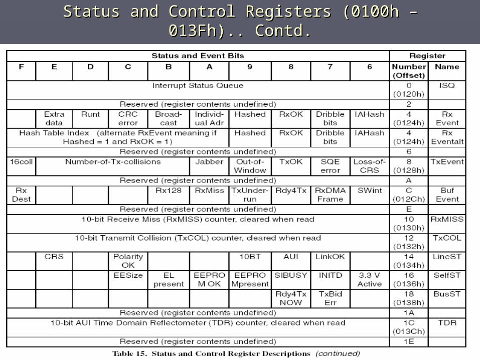
Status and Control Registers (0100h – 013Fh).. Contd.Status and Control Registers (0100h – 013Fh).. Contd.

Section 3Section 3
Initiate Transmit Registers TxCMD, TxLength Initiate Transmit Registers TxCMD, TxLength (0144h – 0146h)(0144h – 0146h)
Section 4Section 4
Address filter Registers – Logical address, Address filter Registers – Logical address, Individual Address (0150h – 0158h)Individual Address (0150h – 0158h)
Section 5Section 5
Receive Frame location – RxStatus, RxLength, Receive Frame location – RxStatus, RxLength, Receive frame length (0400h – 0404h)Receive frame length (0400h – 0404h)
Section 6 Section 6
Transmit Frame location (0A00)Transmit Frame location (0A00)
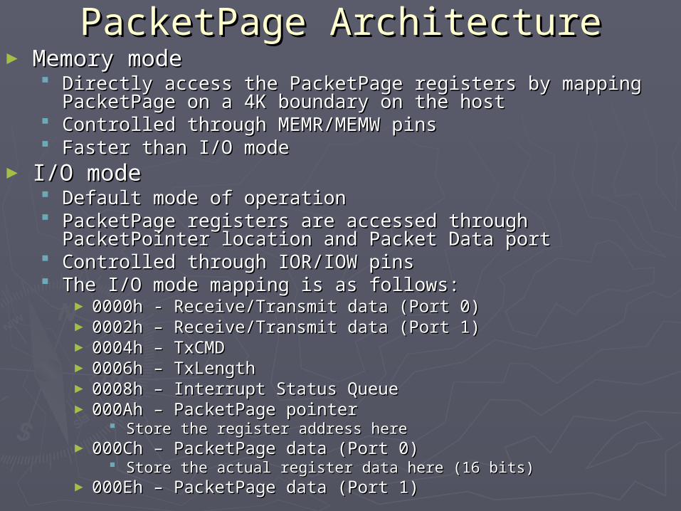
PacketPage ArchitecturePacketPage Architecture► Memory modeMemory mode
Directly access the PacketPage registers by mapping Directly access the PacketPage registers by mapping PacketPage on a 4K boundary on the hostPacketPage on a 4K boundary on the host
Controlled through MEMR/MEMW pinsControlled through MEMR/MEMW pins Faster than I/O modeFaster than I/O mode
► I/O modeI/O mode Default mode of operationDefault mode of operation PacketPage registers are accessed through PacketPointer PacketPage registers are accessed through PacketPointer
location and Packet Data portlocation and Packet Data port Controlled through IOR/IOW pinsControlled through IOR/IOW pins The I/O mode mapping is as follows:The I/O mode mapping is as follows:
► 0000h - Receive/Transmit data (Port 0)0000h - Receive/Transmit data (Port 0)► 0002h – Receive/Transmit data (Port 1)0002h – Receive/Transmit data (Port 1)► 0004h – TxCMD 0004h – TxCMD ► 0006h – TxLength0006h – TxLength► 0008h – Interrupt Status Queue0008h – Interrupt Status Queue► 000Ah – PacketPage pointer000Ah – PacketPage pointer
Store the register address hereStore the register address here► 000Ch – PacketPage data (Port 0)000Ch – PacketPage data (Port 0)
Store the actual register data here (16 bits)Store the actual register data here (16 bits)► 000Eh – PacketPage data (Port 1)000Eh – PacketPage data (Port 1)
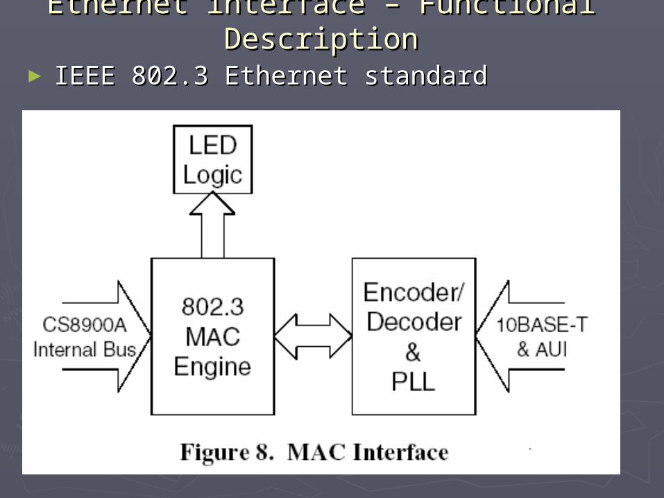
Ethernet interface – Functional Ethernet interface – Functional DescriptionDescription
► IEEE 802.3 Ethernet standardIEEE 802.3 Ethernet standard
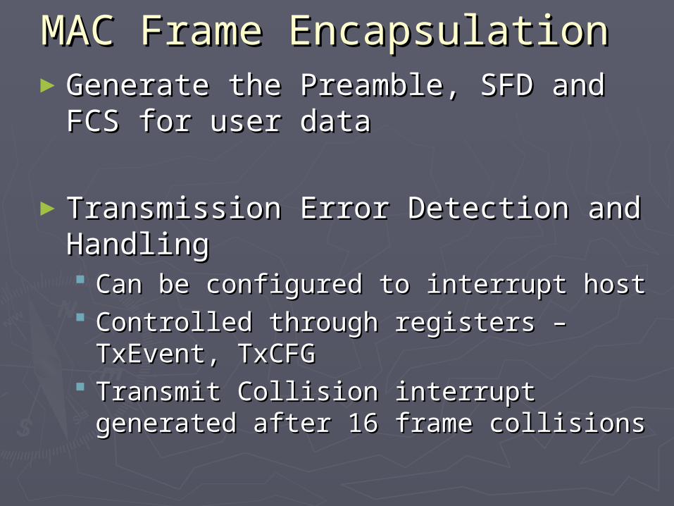
MAC Frame Encapsulation MAC Frame Encapsulation ►Generate the Preamble, SFD and FCS Generate the Preamble, SFD and FCS
for user datafor user data
►Transmission Error Detection and Transmission Error Detection and HandlingHandling Can be configured to interrupt hostCan be configured to interrupt host Controlled through registers – TxEvent, Controlled through registers – TxEvent,
TxCFGTxCFG Transmit Collision interrupt generated Transmit Collision interrupt generated
after 16 frame collisionsafter 16 frame collisions
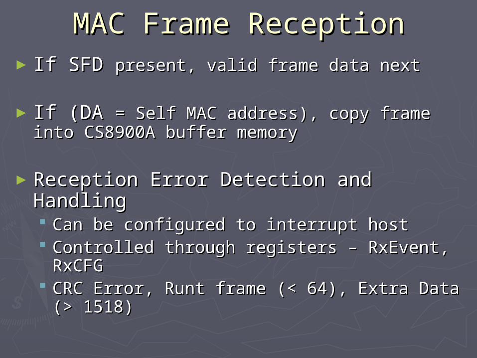
MAC Frame ReceptionMAC Frame Reception► If SFD If SFD present, valid frame data nextpresent, valid frame data next
► If (DA If (DA = Self MAC address), copy frame into = Self MAC address), copy frame into CS8900A buffer memoryCS8900A buffer memory
►Reception Error Detection and HandlingReception Error Detection and Handling Can be configured to interrupt hostCan be configured to interrupt host Controlled through registers – RxEvent, Controlled through registers – RxEvent,
RxCFGRxCFG CRC Error, Runt frame (< 64), Extra Data CRC Error, Runt frame (< 64), Extra Data
(> 1518)(> 1518)
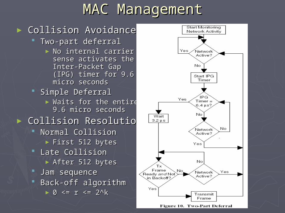
MAC ManagementMAC Management► Collision AvoidanceCollision Avoidance
Two-part deferralTwo-part deferral► No internal carrier sense No internal carrier sense
activates the Inter-activates the Inter-Packet Gap (IPG) timer Packet Gap (IPG) timer for 9.6 micro secondsfor 9.6 micro seconds
Simple DeferralSimple Deferral► Waits for the entire 9.6 Waits for the entire 9.6
micro secondsmicro seconds
► Collision ResolutionCollision Resolution Normal CollisionNormal Collision
► First 512 bytesFirst 512 bytes Late CollisionLate Collision
► After 512 bytesAfter 512 bytes Jam sequenceJam sequence Back-off algorithmBack-off algorithm
► 0 <= r <= 2^k0 <= r <= 2^k
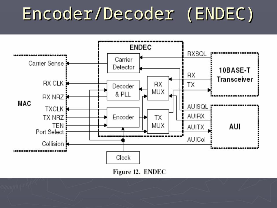
Encoder/Decoder (ENDEC)Encoder/Decoder (ENDEC)
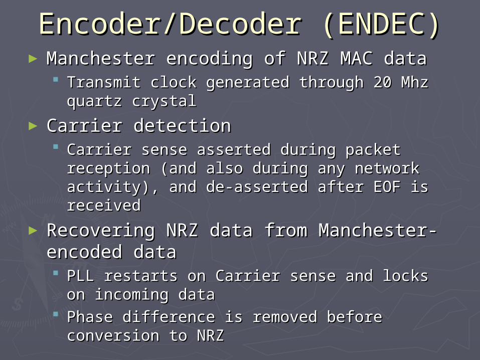
Encoder/Decoder (ENDEC)Encoder/Decoder (ENDEC)►Manchester encoding of NRZ MAC dataManchester encoding of NRZ MAC data
Transmit clock generated through 20 Mhz Transmit clock generated through 20 Mhz quartz crystalquartz crystal
► Carrier detectionCarrier detection Carrier sense asserted during packet reception Carrier sense asserted during packet reception
(and also during any network activity), and de-(and also during any network activity), and de-asserted after EOF is receivedasserted after EOF is received
► Recovering NRZ data from Manchester-Recovering NRZ data from Manchester-encoded dataencoded data PLL restarts on Carrier sense and locks on PLL restarts on Carrier sense and locks on
incoming dataincoming data Phase difference is removed before conversion Phase difference is removed before conversion
to NRZto NRZ
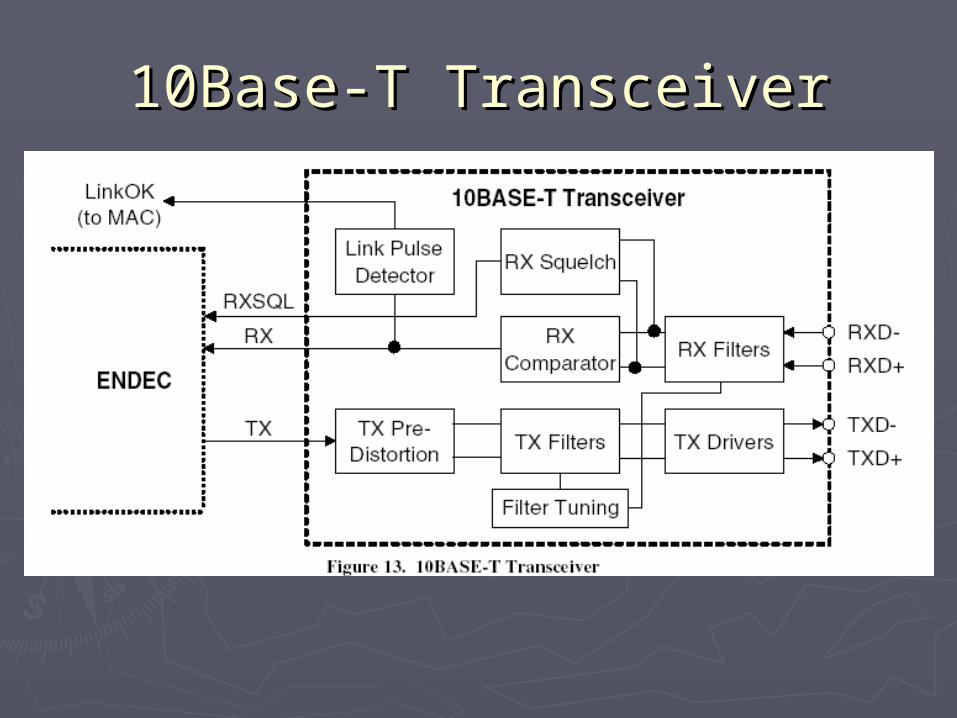
10Base-T Transceiver10Base-T Transceiver
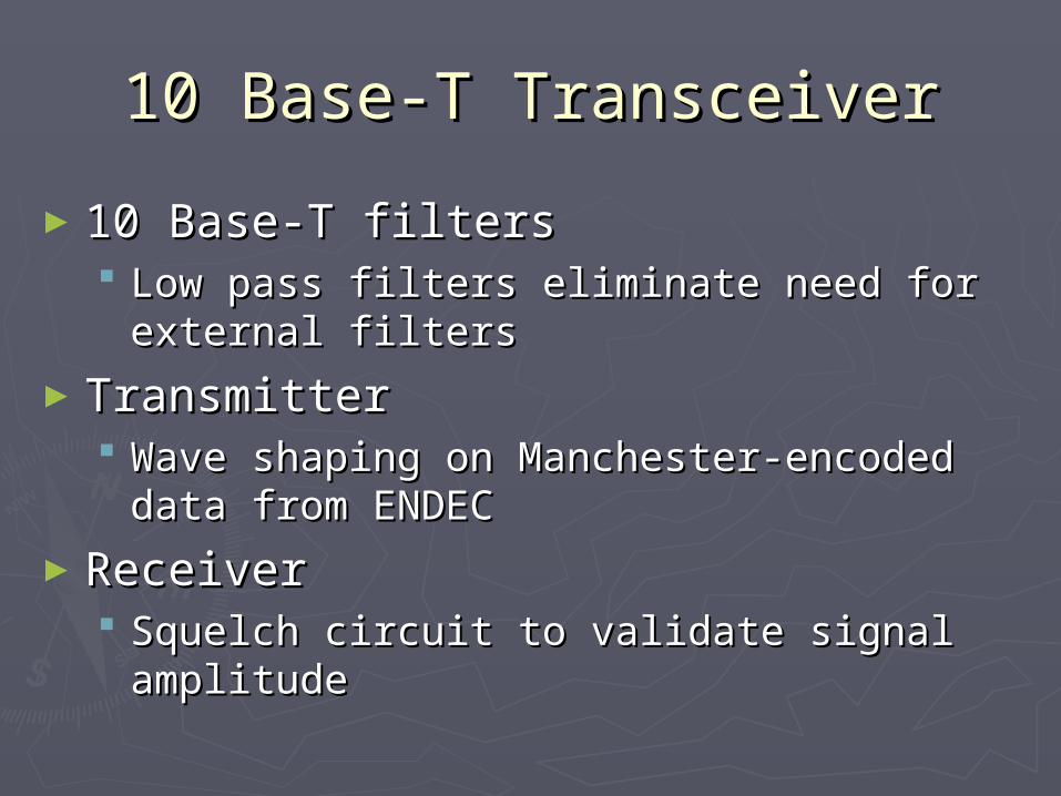
10 Base-T Transceiver10 Base-T Transceiver
►10 Base-T filters10 Base-T filters Low pass filters eliminate need for Low pass filters eliminate need for
external filtersexternal filters
►TransmitterTransmitter Wave shaping on Manchester-encoded Wave shaping on Manchester-encoded
data from ENDECdata from ENDEC
►ReceiverReceiver Squelch circuit to validate signal Squelch circuit to validate signal
amplitudeamplitude
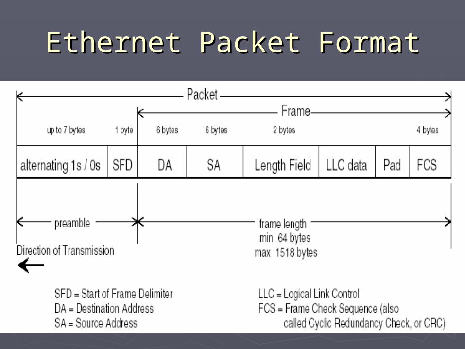
Ethernet Packet FormatEthernet Packet Format
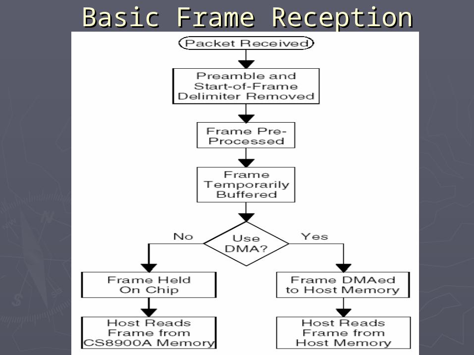
Basic Frame ReceptionBasic Frame Reception
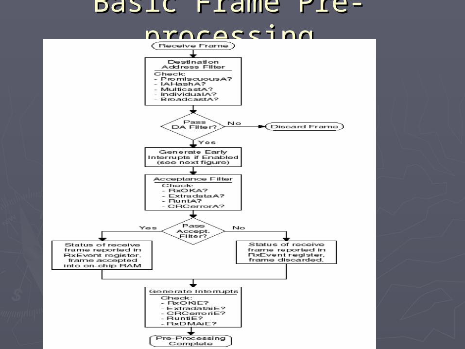
Basic Frame Pre-processingBasic Frame Pre-processing
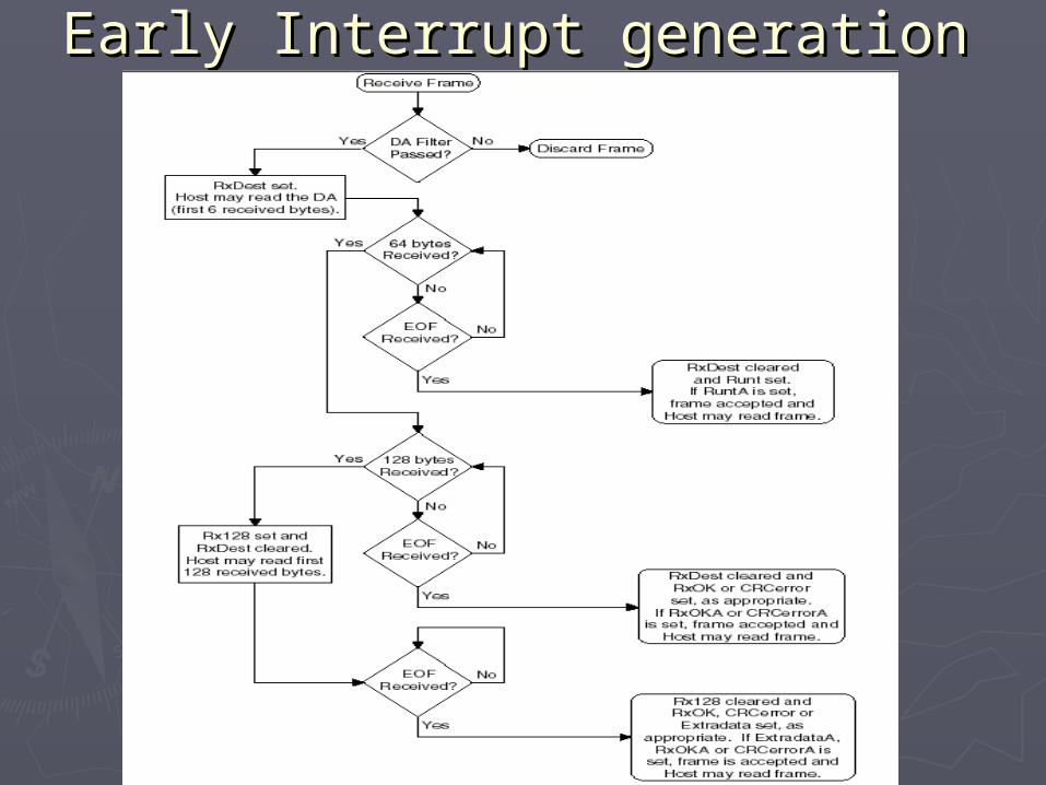
Early Interrupt generationEarly Interrupt generation
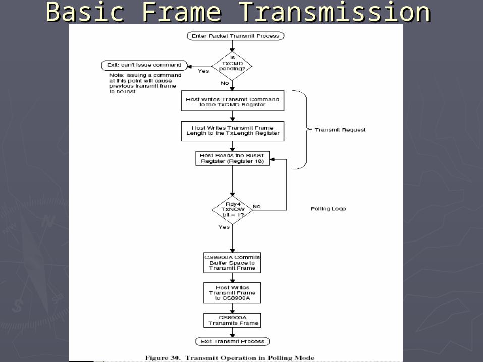
Basic Frame TransmissionBasic Frame Transmission
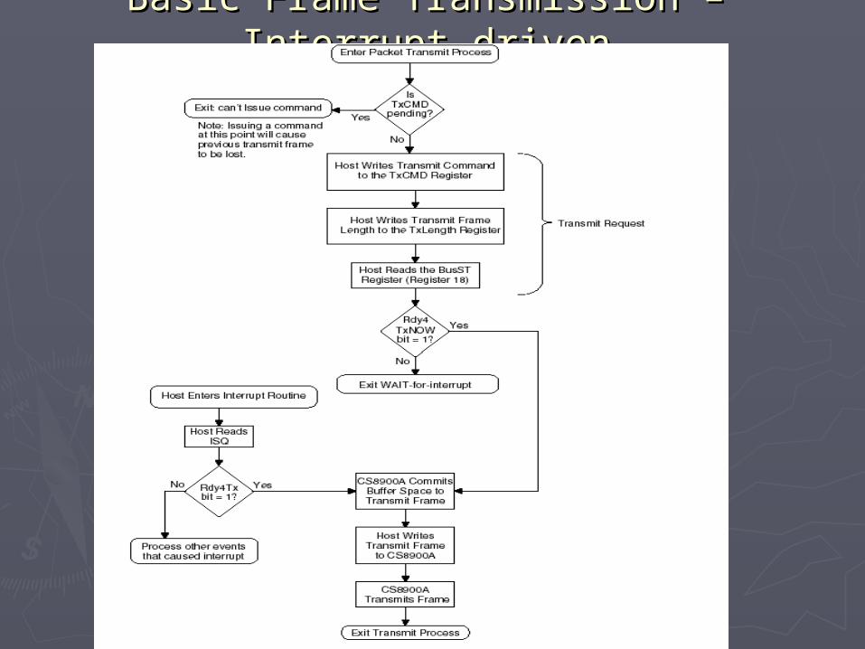
Basic Frame Transmission – Interrupt Basic Frame Transmission – Interrupt drivendriven
ReferenceReference
The CS8900A data sheetThe CS8900A data sheethttp://www.cirrus.com/en/pubs/proDatasheet/cs8900a-http://www.cirrus.com/en/pubs/proDatasheet/cs8900a-
4.pdf4.pdf