Embed Size (px)
Citation preview
1627/11.02
CustomerInformation
Securing Threaded Connections
Edition 27
Fastening technology
efficient, secure, safe

Securing Threaded Connections
2
From Data Sheet 302*): A well designed threaded connection, tightened under controlled conditions, should not usually require additional retention measures!
The most important relationshipsthat determine whether or not athreaded connection is reliable areillustrated in the diagram.
Ever since it was first invented, thethreaded fastener has proven itselfan irreplaceable part of the world offastening technology. Today,threaded fasteners continue asbefore to be one of the mostimportant types of releasablefastener in the fields of construction,assembly and repair. Within thiscategory, the range of different typesof fastener and the uses to whichthey can be put is continuouslyincreasing. The problem of retainingthese fasteners has become ahugely complex subject, which isdifficult to fully comprehend. Thislatest issue of Böllhoff Bulletin willgive you an introduction to thetechnical principles that underpin thesubject of how to retain fastenersand provides an overview of themajor types of locking systemavailable on the market today. Thefollowing information is providedwith the aim of helping you to alwayschoose the best fastener for the job,
based on technical and economicconsiderations. We hope we achieveour aim. Should you require anyfurther advice on finding the rightsolution for your individual
requirements, our applicationstechnology engineers are alwayson hand to help.
Reliability of the threaded connection
Analysis and design ofthe threaded connection
Determination of therequired preload force
Assembly method
Creation of the requiredpreload force
Retention method
Maintenance of therequired preload force
Functional properties ofthe threaded fastener
Ability to withstand theforces and other
influences affecting thethreaded fastener

3
In practice, it is not always possible toachieve a sufficiently secure threadedconnection through good designalone. A range of fastener lockingmethods is available to preventthreaded connections from looseningor falling apart in such cases.It must however be noted that, eventoday, spring washers and otheraccessory elements are still used intheir millions, despite the fact thatthese supposed retainers arecompletely ineffective in high-strengththreaded connections, and thecorresponding standards have longsince been withdrawn by the GermanInstitute for Standardization (DIN).It has long been known that a properlyimplemented threaded connection cangenerate considerably higher clampingforces than could be achieved using aspring washer or tab washer.
To date, the following standards relating to retainers havebe withdrawn by DIN (Deutsches Institut für Normung e. V.):
■ Spring washers (DIN 127, DIN 128 and DIN 6905)
■ Curved spring washers (DIN 137 and DIN 6904)
■ Toothed lock washers (DIN 6797)
■ Serrated lock washers (DIN 6798 and DIN 6908)
■ Tab washers (DIN 93, DIN 432 and DIN 463)
■ Safety cups (DIN 526)
■ Self-locking nuts (DIN 7967)
■ Hexagon Thin Slotted and Castle Nuts (DIN 937)
When used with high-strength threaded fasteners, theretainers defined by these standards neither provide alocking effect, nor are they suitable as a precautionagainst setting.
Comparison of loosening characteristics of various
fastener retention methods under dynamic lateral load
100
80
40
60
20
0
%
0 200 400 600 800 10000
No. load cycles
Pre
load
forc
e, F
s
Non-retained fastener, DIN 933 – M 10 x 30-8.8
Fastener with tooth lock washer as per DIN 6797
Fastener with spring washer as per DIN 127
Serrated washer head fastener or fastener with microencapsulated adhesive
Withdrawn standards
4
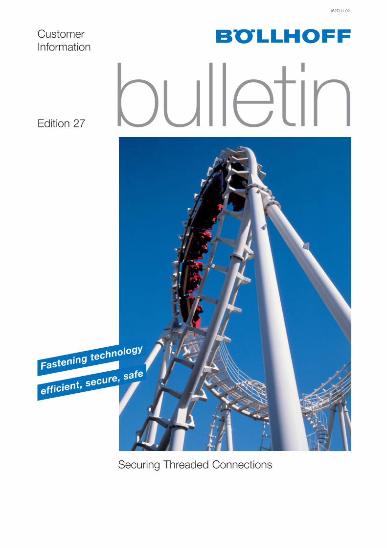
Relationships between force and deformationin preloaded threaded connections
* Exception: Overelastic tightening – this does however require a special tightening procedure.
Threaded connections should bedesigned in such a way that there isno way in which the maximumpossible combined loads could lead tothe yield point of the matedcomponents being exceeded*.The tightening torque must beselected so that the preload forceapplied results in a purely frictionalconnection between the components. Guideline value: Preload force shouldbe at least 75% of the yield strength ofthe threaded fastener.With a clamping length ratio ofLk/DNom > 5, a low number ofcontact surfaces and sufficient preloadforce, metallic components do notrequire additional retention measures,provided that no increased dynamicloads occur, particularly perpendicularto the axis of the fastener.
Clamping length
Preload force
Washer
Threaded fastener
Tightening torque
WasherNut
Clamped components
Contact surfaces
Preload diagram
Applying a tightening torque to createa connection indirectly causes apreload force to act on the fastener,which in turn leads to lengthening ofthe fastener and a contraction of thecomponents. Any forces that occur inuse are distributed according theelasticity of the mated parts. Undertensile stress, the load on the fasteneris only reduced slightly, however theremaining clamping force is decreasedsignificantly. Important: Any compressible springcomponents used in conjunction withthe fastener will affect the load ratios.
5
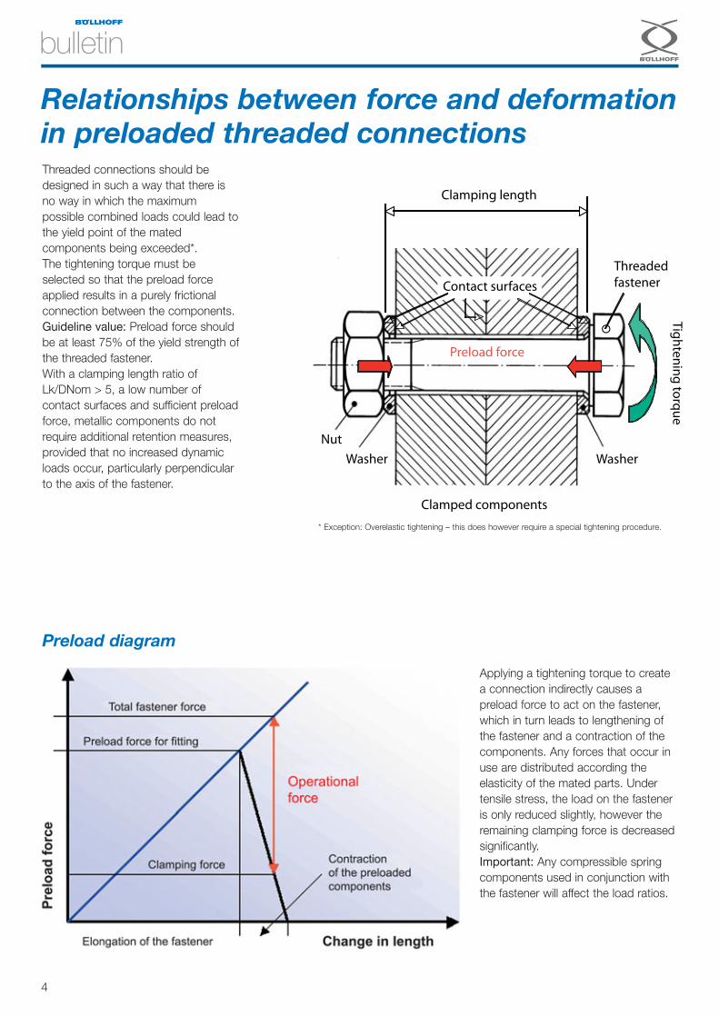
Effect of preload force and thread pitchThe friction angle, μ, describes theratio of the normal force, FG, to thefrictional force, FR that it generates. Taken in the context of a threadedconnection, the normal force and thepreload force can be considered equalas a first approximation.Provided that the pitch angle, φ, of thethread is smaller than the frictionangle, μ, the thread will be self-locking.
1 Helix2 Uncoiled helix
1
d2
Ph
d2 · π
2
�
�
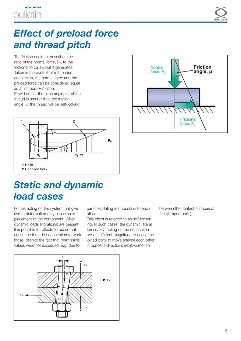
Static and dynamic load casesForces acting on the system that giverise to deformation may cause a dis-placement of the component. Whendynamic loads (vibrations) are present,it is possible for effects to occur thatcause the threaded connection to workloose, despite the fact that permissiblevalues were not exceeded, e.g. due to
parts oscillating in opposition to eachother. This effect is referred to as self-loosen-ing. In such cases, the dynamic lateralforces, FQ, acting on the connectionare of sufficient magnitude to cause thejoined parts to move against each otherin opposite directions (relative motion
between the contact surfaces ofthe clamped parts).
FQ
FQ
S
FV
FV
FL
FL

6
It is not uncommon for threadedconnections to fail due to self-loosening when subjected to dynamicloads, particularly where the forcesact perpendicularly to the axis of theconnection.This can result in defects anddamage caused by the partial orcomplete loss of preload force in theform of fatigue cracks or unscrewingof connections.Connections unscrew because of theinternal unscrewing torque within theconnection, which occurs whenforces act to overcome the frictionalconnection between the head of thefastener and the part and/or betweenthe fastener and the internal thread.Connections formed using aclearance through-hole (nut and bolt)are particularly at risk of this type offailure as there is more potential forthe fastener to work loose.
How self-loosening occurs
Guideline
Connections are usually sufficiently secure
simply as a result of the combination of
frictional resistance and the clamping force
between the nut/fastener and the clamped
parts.
Provided that the clamping length is appro-
priate (guideline value > 5d), threaded fas-
teners do not generally require additional
retention measures, even when subject to
dynamic load.
If loads occur that create a situation where
design measures alone are insufficient to
maintain a connection, then additional
retainers must be used.
UnscrewingLoosening
Creep = Time-dependentplastification due to
exceeding the elastic limitof the material.
Bolt, nut,clamped parts
Setting due to smoothingof surface finish at the
contact surfaces
Total due to lossof self-locking
effect
Partial due to reductionin self-locking
Thread, head and nutcontact surfaces,
component contactsurfaces
Relative motion of the contact
surfaces
Relaxation of theinternally threaded
part under axial load
*) Data Sheet 302: "Sicherungen für Schraubverbindungen", O. Strelow Beratungsstelle für Stahlverwendung, Düsseldorf, Germany
Causes of self-loosening of a threaded connection
Loss of preload force as a result of self-loosening
Externalunscrewing
torque
7
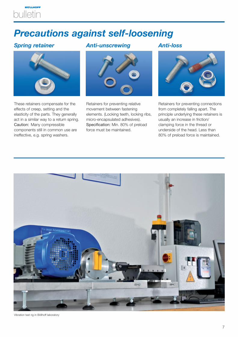
These retainers compensate for theeffects of creep, setting and theelasticity of the parts. They generallyact in a similar way to a return spring.Caution: Many compressiblecomponents still in common use areineffective, e.g. spring washers.
Retainers for preventing connectionsfrom completely falling apart. Theprinciple underlying these retainers isusually an increase in friction/clamping force in the thread orunderside of the head. Less than80% of preload force is maintained.
Retainers for preventing relativemovement between fasteningelements. (Locking teeth, locking ribs,micro-encapsulated adhesives).Specification: Min. 80% of preloadforce must be maintained.
Precautions against self-looseningSpring retainer Anti-unscrewing Anti-loss
Vibration test rig in Böllhoff laboratory
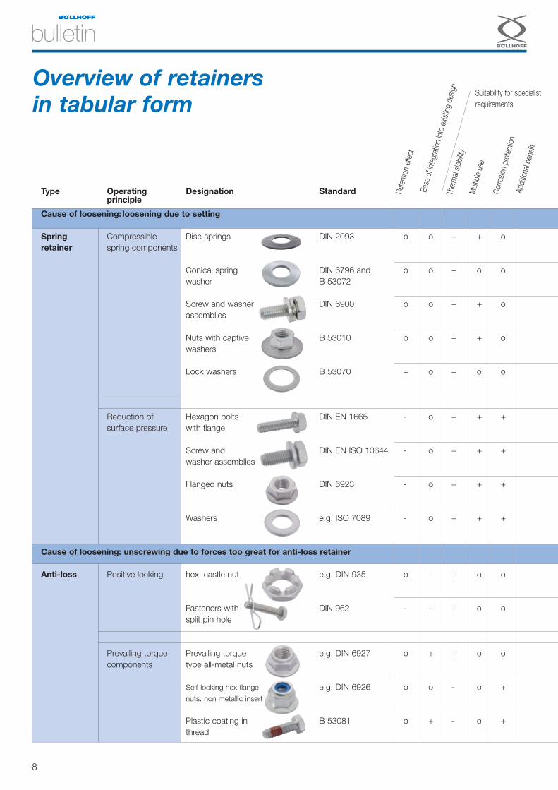
Type Operating Designation Standardprinciple
Cause of loosening: loosening due to setting
Spring Compressible Disc springs DIN 2093 o o + + oretainer spring components
Conical spring DIN 6796 and o o + o owasher B 53072
Screw and washer DIN 6900 o o + + oassemblies
Nuts with captive B 53010 o o + + owashers
Lock washers B 53070 + o + o o
Reduction of Hexagon bolts DIN EN 1665 - o + + +surface pressure with flange
Screw and DIN EN ISO 10644 - o + + +washer assemblies
Flanged nuts DIN 6923 - o + + +
Washers e.g. ISO 7089 - o + + +
Cause of loosening: unscrewing due to forces too great for anti-loss retainer
Anti-loss Positive locking hex. castle nut e.g. DIN 935 o - + o o
Fasteners with DIN 962 - - + o osplit pin hole
Prevailing torque Prevailing torque e.g. DIN 6927 o + + o ocomponents type all-metal nuts
Self-locking hex flange e.g. DIN 6926 o o - o +nuts: non metallic insert
Plastic coating in B 53081 o + - o +thread
8
Overview of retainers in tabular form
Rete
ntion
effe
ct
Ease
of in
tegr
ation
into
exis
ting
desig
nTh
erm
al st
abilit
yM
ultipl
e us
e
Corro
sion
prot
ectio
nAd
dition
al be
nefit
Suitability for specialistrequirements

o + o o + o Clamping Unlimitedlength
o + o o + o Clamping Unlimitedlength
o + + o o o Clamping Unlimitedlength
o + + o o o Clamping Unlimitedlength
o + o o o o Clamping Unlimitedlength
+ + + + o + Neutral Unlimited
+ + + + o o Clamping Unlimitedlength
+ + + + + + Neutral Unlimited
+ + o + + o Clamping Unlimitedlength
+ + - + - - Various Unlimited
+ + - + - - Negative Unlimited
+ o + + o o Tightening Unlimitedtorque
+ o + + o o Almost none Unlimited
+ o + + - o Almost none Unlimited
9
Type Operating Designationprinciple
Cause of loosening: unscrewing due to forces too great for anti-
Anti-loss Other method Thread forming screw
Self-locking thread
HELICOIL®
screwlock
Lock nut
Fine pitch thread
Anti- Locking RIPP LOCK®
unscrewing components lock washers
Ribbed fastener/nut
Serrated washer head screws/nuts
Profiled washer
Adhesive Microencapsulatedcomponents adhesive
Liquid adhesive
Wedge locking NORD-LOCK®
method Paired wedge-locking washers
Depe
nds
on p
reloa
d fo
rce
Suita
ble fo
r thr
ead
lubric
ation
Effo
rt re
quire
d to
inst
allHa
rdne
ss o
f cou
nter
sur
face
Cost
of c
ompo
nent
Addit
ional
spac
e re
quire
dEf
fect
on
conn
ectio
n
Shelf
life
10
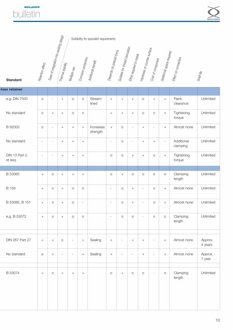
Standard
-loss retainer
e.g. DIN 7500 o - + o o Stream- + + + o + + Flank Unlimitedlined clearance
No standard o + + o o + + + o o + Tightening Unlimitedtorque
B 62000 o - + + + Increases + o - + - + Almost none Unlimitedstrength
No standard - - + + + - o - + + - Additional Unlimitedclamping
DIN 13 Part 2 - - + + + o o + + o + Tightening Unlimitedet seq. torque
B 53065 + o + + + o + o o o o Clamping Unlimitedlength
B 158 + o + o o - o + - o + Almost none Unlimited
B 53085, B 151 + o + o - - o + - o + Almost none Unlimited
e.g. B 53072 + o + o o - o o - o o Clamping Unlimitedlength
DIN 267 Part 27 + + o - + Sealing + - + + - + Almost none Approx. 4 years
No standard o + - - + Sealing + - - + - + Almost none Approx. 1 year
B 53074 + o + + + o + o o - o Clamping Unlimitedlength
Rete
ntion
effe
ct
Ease
of in
tegr
ation
into
exis
ting
desig
nTh
erm
al st
abilit
yM
ultipl
e us
e
Corro
sion
prot
ectio
nAd
dition
al be
nefit
Depe
nds
on p
reloa
d fo
rce
Suita
ble fo
r thr
ead
lubric
ation
Effo
rt re
quire
d to
inst
allHa
rdne
ss o
f cou
nter
sur
face
Cost
of c
ompo
nent
Addit
ional
spac
e re
quire
dEf
fect
on
conn
ectio
n
Shelf
life
Suitability for specialist requirements

11
1. Mechanical thread retention methods
Differentiation of retention typesAdhesive Resistance Locking
Adhesive coating asper DIN 267 Part 27
Fasteners with mechanical self-locking thread
Fasteners withribs/locking teeth
Lock wire, split pin, etc.
Self-tapping fasteners as analternative to pre-tapped threads
Prevailing torque typeinternally threadedcomponents
Lock washers
Lockingcoating asper DIN 267Part 28
Liquid adhesive,e.g. Loctite
2. Chemical thread
retention methods1. Mechanical thread
retention methods
■ Prevailing torque Mostly internally threaded components, e.g. prevailing torque typenuts (DIN 6927, DIN 6926, DIN 985), Fujilok nut (B 53030), Vargal(B 53040), etc.
■ Locking Serrated washer head fasteners (B 53085, B 151 and B 158), serrat-ed washer head nuts (B 196, B 193 and B 53012), lock washers (e.g.RIPP LOCK®).
■ Sprung e.g. disc springs (DIN 2093), conical spring washers (DIN 6796 andB 53072), screw and washer assemblies (DIN 6900-5), nuts withcaptive washers (B 53010), etc.
■ Lock nut Any type of nut that is clamped by an additional internally-threadedcomponent – these are not true retainers.
■ Positive locking Hexagon slotted nuts and castle nuts (DIN 935 and DIN 979),fasteners with split pin hole (DIN 962).
■ Thread forming Thread retention as added benefit
There are also numerous types of retainer that combine two or more different types of mechanical retention (e.g. RIPPLOCK® lock washers, NORD-LOCK® washers).
12
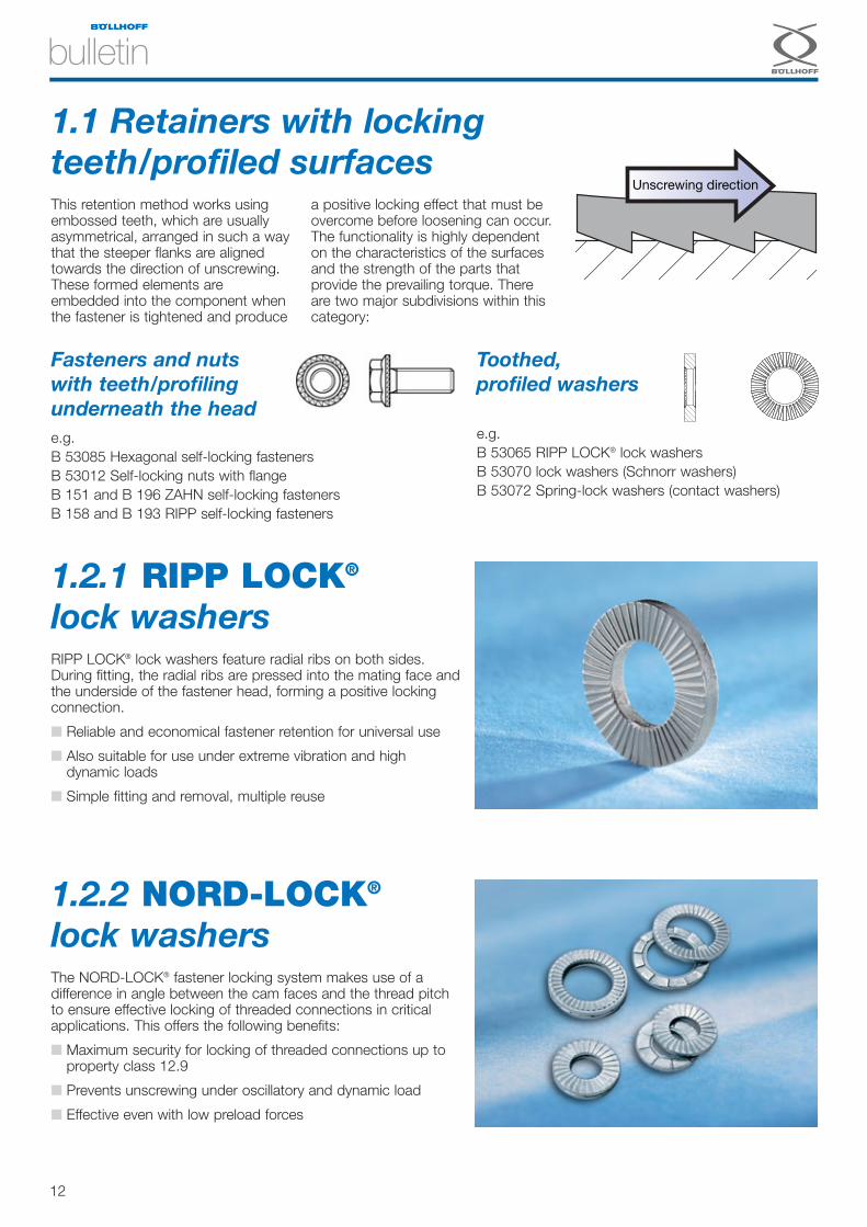
Unscrewing direction
1.1 Retainers with locking teeth/profiled surfacesThis retention method works usingembossed teeth, which are usuallyasymmetrical, arranged in such a waythat the steeper flanks are alignedtowards the direction of unscrewing.These formed elements areembedded into the component whenthe fastener is tightened and produce
a positive locking effect that must beovercome before loosening can occur.The functionality is highly dependenton the characteristics of the surfacesand the strength of the parts thatprovide the prevailing torque. Thereare two major subdivisions within thiscategory:
Fasteners and nuts with teeth/profiling underneath the head e.g.B 53085 Hexagonal self-locking fastenersB 53012 Self-locking nuts with flangeB 151 and B 196 ZAHN self-locking fasteners B 158 and B 193 RIPP self-locking fasteners
Toothed, profiled washers
e.g.B 53065 RIPP LOCK® lock washersB 53070 lock washers (Schnorr washers)B 53072 Spring-lock washers (contact washers)
1.2.2 NORD-LOCK®
lock washersThe NORD-LOCK® fastener locking system makes use of adifference in angle between the cam faces and the thread pitchto ensure effective locking of threaded connections in criticalapplications. This offers the following benefits:
■ Maximum security for locking of threaded connections up toproperty class 12.9
■ Prevents unscrewing under oscillatory and dynamic load
■ Effective even with low preload forces
1.2.1 RIPP LOCK®
lock washersRIPP LOCK® lock washers feature radial ribs on both sides.During fitting, the radial ribs are pressed into the mating face andthe underside of the fastener head, forming a positive lockingconnection.
■ Reliable and economical fastener retention for universal use
■ Also suitable for use under extreme vibration and highdynamic loads
■ Simple fitting and removal, multiple reuse
13
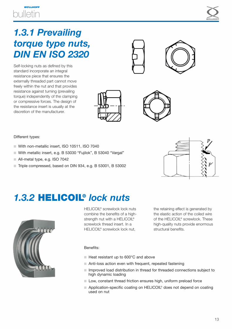
1.3.2 HELICOIL® lock nutsHELICOIL® screwlock lock nuts combine the benefits of a high-strength nut with a HELICOIL®
screwlock thread insert. In a HELICOIL® screwlock lock nut,
the retaining effect is generated by the elastic action of the coiled wire of the HELICOIL® screwlock. Thesehigh-quality nuts provide enormousstructural benefits.
Benefits:
■ Heat resistant up to 600°C and above
■ Anti-loss action even with frequent, repeated fastening
■ Improved load distribution in thread for threaded connections subject tohigh dynamic loading
■ Low, constant thread friction ensures high, uniform preload force
■ Application-specific coating on HELICOIL® does not depend on coatingused on nut
Different types:
■ With non-metallic insert, ISO 10511, ISO 7040
■ With metallic insert, e.g. B 53030 “Fujilok”, B 53040 “Vargal”
■ All-metal type, e.g. ISO 7042
■ Triple compressed, based on DIN 934, e.g. B 53001, B 53002
1.3.1 Prevailing torque type nuts,DIN EN ISO 2320 Self-locking nuts as defined by thisstandard incorporate an integralresistance piece that ensures theexternally threaded part cannot movefreely within the nut and that providesresistance against turning (prevailingtorque) independently of the clampingor compressive forces. The design ofthe resistance insert is usually at thediscretion of the manufacturer.
14
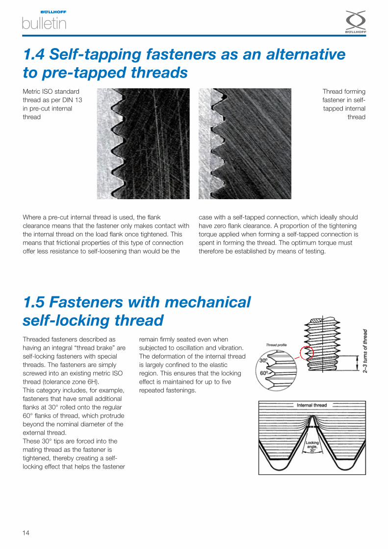
1.4 Self-tapping fasteners as an alternativeto pre-tapped threadsMetric ISO standardthread as per DIN 13in pre-cut internalthread
Thread formingfastener in self-tapped internal
thread
Where a pre-cut internal thread is used, the flankclearance means that the fastener only makes contact withthe internal thread on the load flank once tightened. Thismeans that frictional properties of this type of connectionoffer less resistance to self-loosening than would be the
case with a self-tapped connection, which ideally shouldhave zero flank clearance. A proportion of the tighteningtorque applied when forming a self-tapped connection isspent in forming the thread. The optimum torque musttherefore be established by means of testing.
1.5 Fasteners with mechanical self-locking threadThreaded fasteners described ashaving an integral “thread brake” areself-locking fasteners with specialthreads. The fasteners are simplyscrewed into an existing metric ISOthread (tolerance zone 6H).This category includes, for example,fasteners that have small additionalflanks at 30° rolled onto the regular60° flanks of thread, which protrudebeyond the nominal diameter of theexternal thread.These 30° tips are forced into themating thread as the fastener istightened, thereby creating a self-locking effect that helps the fastener
remain firmly seated even whensubjected to oscillation and vibration.The deformation of the internal threadis largely confined to the elasticregion. This ensures that the lockingeffect is maintained for up to fiverepeated fastenings.
15
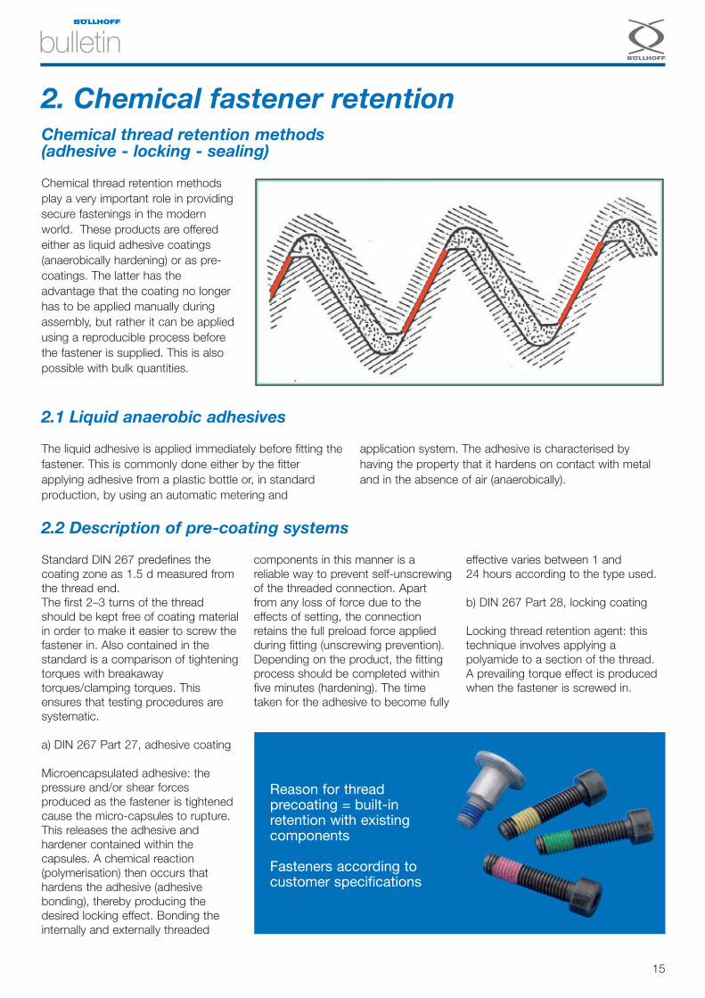
Standard DIN 267 predefines thecoating zone as 1.5 d measured fromthe thread end.The first 2–3 turns of the threadshould be kept free of coating materialin order to make it easier to screw thefastener in. Also contained in thestandard is a comparison of tighteningtorques with breakawaytorques/clamping torques. Thisensures that testing procedures aresystematic.
a) DIN 267 Part 27, adhesive coating
Microencapsulated adhesive: thepressure and/or shear forcesproduced as the fastener is tightenedcause the micro-capsules to rupture.This releases the adhesive andhardener contained within thecapsules. A chemical reaction(polymerisation) then occurs thathardens the adhesive (adhesivebonding), thereby producing thedesired locking effect. Bonding theinternally and externally threaded
components in this manner is areliable way to prevent self-unscrewingof the threaded connection. Apartfrom any loss of force due to theeffects of setting, the connectionretains the full preload force appliedduring fitting (unscrewing prevention). Depending on the product, the fittingprocess should be completed withinfive minutes (hardening). The timetaken for the adhesive to become fully
effective varies between 1 and24 hours according to the type used.
b) DIN 267 Part 28, locking coating
Locking thread retention agent: thistechnique involves applying apolyamide to a section of the thread.A prevailing torque effect is producedwhen the fastener is screwed in.
Chemical thread retention methodsplay a very important role in providingsecure fastenings in the modernworld. These products are offeredeither as liquid adhesive coatings(anaerobically hardening) or as pre-coatings. The latter has theadvantage that the coating no longerhas to be applied manually duringassembly, but rather it can be appliedusing a reproducible process beforethe fastener is supplied. This is alsopossible with bulk quantities.
2. Chemical fastener retentionChemical thread retention methods (adhesive - locking - sealing)
The liquid adhesive is applied immediately before fitting thefastener. This is commonly done either by the fitterapplying adhesive from a plastic bottle or, in standardproduction, by using an automatic metering and
application system. The adhesive is characterised byhaving the property that it hardens on contact with metaland in the absence of air (anaerobically).
Reason for threadprecoating = built-inretention with existingcomponents
Fasteners according tocustomer specifications
2.1 Liquid anaerobic adhesives
2.2 Description of pre-coating systems
16
The axial clearance between theexternal and internal threads is filled inby the coating, which results in highsurface pressure (positive locking)between the coated thread and theflanks of the uncoated mating thread.
This creates the desired locking effect.Loss-prevention methods can notprevent partial unscrewing, but arecertainly able to prevent the threadedconnection falling apart completely.Multiple use is possible here, however
the clamping forces are reduced witheach fastening.
Material Effect Coating
Polyamide, spot Locking 1 Red, blue or green
Polyamide, all round Locking, sealing 2 Red, blue or green
Polyamide, spot, heat res. Locking (heat resistant) 3 Brown
Polyamide, all round, heat res. Locking, sealing (heat resistant) 4 Brown
Precote 30 Med. strength adhesive, thread μ 0.10–0.15 5 Yellow
Precote 80 V. high strength adhesive, sealing, thread μ 0.25 0.28 6 Red
Precote 85 High strength adhesive, sealing, thread μ 0.10–0.15 7 Turquoise
Precote 85-8 Adhesive, sealing, thread μ 0.10–0.15 8 Turquoise
Scotch Grip 2353 High strength adhesive, sealing, thread μ 0.13–0.18 9 Blue
Scotch Grip 2510 High strength adhesive, sealing, thread μ 0.12–0.15 0 Orange
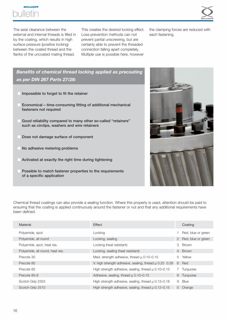
Benefits of chemical thread locking applied as precoating
as per DIN 267 Parts 27/28:
■ Impossible to forget to fit the retainer
■ Economical – time-consuming fitting of additional mechanicalfasteners not required
■ Good reliability compared to many other so-called “retainers”such as circlips, washers and wire retainers
■ Does not damage surface of component
■ No adhesive metering problems
■ Activated at exactly the right time during tightening
■ Possible to match fastener properties to the requirementsof a specific application
Chemical thread coatings can also provide a sealing function. Where this property is used, attention should be paid toensuring that the coating is applied continuously around the fastener or nut and that any additional requirements havebeen defined.

17
ECOTECH –ECOnomic TECHnical Engineering
Securing threaded connections willbecome an increasingly importantissue in future because designerseither do not or cannot always takefull account of the full range ofparameters affecting threadedconnections. At the same time,product liability and safetyrequirements are becoming ever morestringent.Thread retention systems that do notrequire an additional retainercomponent offer higher processsecurity overall and will dominate thismarket. Particularly important in this
respect are chemical thread retentionmethods, fasteners and nuts withlocking teeth, self-tapping fastenersand, to a limited extent, self-lockingnuts as defined by DIN EN ISO 2320. Specialist retainers that provideadditional beneficial properties for theconnection beyond the retention effect(e.g. NORD-LOCK® washers,HELICOIL® screwlock) will increasinglybe used.Retainers that work by generating apositive fit (castle nut with split pin,etc.) and those for which therespective standards have been
withdrawn (spring washers, toothedlock washers, etc.) should be avoidedwherever possible.Modern mechanical systems are oftennot standardised and/or are subject topatents, utility models and otherprotective rights.
Looking ahead
We are pleased to offer thefollowing services according toindividual requirements:
■ Assembly optimisation, including on-site work at the customer
■ Standardisation and optimisation
■ Information and consultancy
■ Customer seminars
After defining the specificrequirements of a project, ourApplication Engineering departmentworks together with the customer todevelop recommended solutions,and provides design support whererequired.
Benefits of using ECOTECH
■ Shorter development times
■ Documented basis for decision making
■ Latest fastening technology
■ Reduction of storage costs
■ Manufacturing process optimisation
■ Optimisation of the cost of assemblies
Important
We reserve the right to make technical modifications.Reproduction in whole or in part without express permission isprohibited. Protection notices for restricting the use of documents and productsapply in accordance with DIN ISO 16016.
The information in this brochure draws on general technical regulationsand on Böllhoff’s own laboratory experiments and experience. Our aim in presenting this information is to document a certain level ofknowledge in a specialist subject. Actual physical behaviour and results may vary between applicationsdepending on the circumstances and conditions of each individualcase. It is the responsibility of the user to ensure the suitability of eachindividual component for each specific application as part of theirdesign process. Böllhoff accepts no responsibility whatsoever for damages that mayoccur.
Böllhoff GroupePlease find your local contact on www.boellhoff.com
or contact us under [email protected]
Böllhoff International with companies in:
Argentina
Austria
Brazil
Canada
China
Czech Republic
France
Germany
Hungary
India
Italy
Japan
Mexico
Poland
Romania
Russia
Slovakia
Spain
Turkey
United Kingdom
USA
Apart from these 21 countries, Böllhoff supports its international customers in other important industrial markets in close partnership
with agents and dealers.