Embed Size (px)
DESCRIPTION
manual de taller
Citation preview


.
1 - 1

.
FOREWORDFOREWORD
FOREWORDThis manual provides rules and guidelines which will help you use this machine safely and effectively. Theprecautions in this manual must be followed at all times when performing operation and maintenance. Mostaccidents are caused by the failure to follow fundamental safety rules for the operation and maintenance ofmachines. Accidents can be prevented by knowing beforehand conditions that may cause a hazard whenperforming operation and maintenance.
WARNINGOperators and maintenance personnel must always do as follows before beginning operation or maintenance.
Always be sure to read and understand this manual thoroughly before performing operation and maintenance.
Read the safety messages given in this manual and the safety labels affixed to the machine thoroughly and be sure that youunderstand them fully.
Keep this manual in the storage location for the operation and maintenance manual given below, and have all personnel read itperiodically.
If this manual has been lost or has become dirty and cannot be read, request a replacement manual immediately from Komatsuor your Komatsu distributor.
If you sell the machine, be sure to give this manual to the new owners together with the machine.
Komatsu delivers machines that comply with all applicable regulations and standards of the country to which it has been shipped.If this machine has been purchased in another country or purchased from someone in another country, it may lack certain safetydevices and specifications that are necessary for use in your country. If there is any question about whether your productcomplies with the applicable standards and regulations of your country, consult Komatsu or your Komatsu distributor beforeoperating the machine.
Location to keep operation & maintenance manual In door pocket inside of cab door
1 - 2

.
FOREWORD FOREWORD
1 - 3
.
FOREWORDFOREWORD
1 - 4

.
FOREWORD SAFETY INFORMATION
SAFETY INFORMATIONTo enable you to use this machine safely, safety precautions and labels are given in this manual and affixed to themachine to give explanations of situations involving potential hazards and of the methods of avoiding suchsituations.
Signal words
The following signal words are used to inform you that there is a potential hazardous situation that may lead topersonal injury or damage.In this manual and on machine labels, the following signal words are used to express the potential level of hazard.
Indicates an imminently hazardous situation which, if not avoided, will result in death orserious injury.
Indicates a potentially hazardous situation which, if not avoided, could result in death orserious injury.
Indicates a potentially hazardous situation which, if not avoided, may result in minor ormoderate injury. It may also be used to alert against unsafe practices.
Example of safety message using signal word
WARNINGWhen standing up from the operator's seat, always place the lock lever inthe LOCK position.If you accidentally touch the control levers when they are not locked, thismay cause a serious injury or death.
Other signal words
In addition to the above, the following signal words are used to indicate precautions that should be followed toprotect the machine or to give information that is useful to know.
This word is used for precautions that must be taken to avoid actions which could shortenthe life of the machine.
This word is used for information that is useful to know.
1 - 5

.
FOREWORDSAFETY INFORMATION
Safety labels
Safety labels are affixed to the machine to inform the operator or maintenance worker on the spot when carrying outoperation or maintenance of the machine that may involve hazard.This machine uses "Safety labels using words" and "Safety labels using pictograms" to indicate safety procedures.
Example of safety label using words
Safety labels using pictogramSafety pictograms use a picture to express a level of hazardouscondition equivalent to the signal word. These safety pictogramsuse pictures in order to let the operator or maintenance workerunderstand the level and type of hazardous condition at all times.Safety pictograms show the type of hazardous condition at the topor left side, and the method of avoiding the hazardous condition atthe bottom or right side. In addition, the type of hazardous conditionis displayed inside a triangle and the method of avoiding thehazardous condition is shown inside a circle.
Komatsu cannot predict every circumstance that might involve a potential hazard in operation and maintenance.Therefore, the safety messages in this manual and on the machine may not include all possible safety precautions.If any procedures or actions not specifically recommended or allowed in this manual are used, it is your responsibilityto take the necessary steps to ensure safety.In no event should you engage in prohibited uses or actions described in this manual.
The explanations, values, and illustrations in this manual were prepared based on the latest information availableat that time. Continuing improvements in the design of this machine can lead to changes in detail which may notbe reflected in this manual. Consult Komatsu or your Komatsu distributor for the latest available information of yourmachine or for questions regarding information in this manual.
The numbers in circles in the illustrations correspond to the numbers in ( ) in the text. (For example: 1 (1))
1 - 6

.
FOREWORD INTRODUCTION
INTRODUCTIONThis Komatsu machine is designed to be used mainly for the following work:
DozingCutting into hard or frozen ground or ditchingFelling trees, removing stumpsPushingRipping
For further details, see "WORK POSSIBLE USING BULLDOZER (PAGE 3-112)" and "RIPPER OPERATION(PAGE 3-119)".
FRONT/REAR, LEFT/RIGHT DIRECTIONS OF MACHINE
(1)(2)
Operator's seatSprocket
(A)(B)
FrontRear
(C)(D)
LeftRight
In this manual, the terms front, rear, left, and right refer to the travel direction as seen from the operator's seat whenthe operator's seat is facing the front and the sprocket is at the rear of the machine.
1 - 7

.
FOREWORDNECESSARY INFORMATION
NECESSARY INFORMATIONWhen requesting service or ordering replacement parts, please inform your Komatsu distributor of the followingitems.
MACHINE SERIAL NO. PLATE AND POSITIONUnder the front of the console box on the right side of the operator's seat.
ENGINE SERIAL NO. PLATE AND POSITIONThis is at the rear of the exhaust manifold, on the left side of the engine as seen from the fan. (It is on the right sideof the aftercooler as seen from the EMISSION CONTROL INFORMATION LABEL.)
1 - 8

.
FOREWORD NECESSARY INFORMATION
BLADE SERIAL NO. PLATE POSITIONThis is located on the upper right of blade back surface.
RIPPER SERIAL NO. PLATE POSITIONThis is located on the left side surface of ripper beam.
POSITION OF SERVICE METEROn top of the machine monitor
1 - 9

.
FOREWORDNECESSARY INFORMATION
TABLE TO ENTER SERIAL NO. AND DISTRIBUTOR
Machine serial No.
Engine serial No.
Distributor name
Address
Service Personnel
Phone/Fax
1 - 10

.
FOREWORD CONTENTS
CONTENTSFOREWORD 1- 1 FOREWORD 1- 2 SAFETY INFORMATION 1- 5 INTRODUCTION 1- 7 FRONT/REAR, LEFT/RIGHT DIRECTIONS OF MACHINE 1- 7 NECESSARY INFORMATION 1- 8 MACHINE SERIAL NO. PLATE AND POSITION 1- 8 ENGINE SERIAL NO. PLATE AND POSITION 1- 8 BLADE SERIAL NO. PLATE POSITION 1- 9 RIPPER SERIAL NO. PLATE POSITION 1- 9 POSITION OF SERVICE METER 1- 9 TABLE TO ENTER SERIAL NO. AND DISTRIBUTOR 1- 10SAFETY 2- 1 SAFETY 2- 2 SAFETY LABELS 2- 4 POSITIONS OF SAFETY PICTOGRAMS 2- 4 SAFETY LABELS 2- 5 GENERAL PRECAUTIONS 2- 9 PRECAUTIONS FOR OPERATION 2- 19 BEFORE STARTING ENGINE 2- 19 OPERATION 2- 21 TRANSPORTATION 2- 24 BATTERY 2- 24 TOWING 2- 26 PRECAUTIONS FOR MAINTENANCE 2- 27OPERATION 3- 1 GENERAL VIEW 3- 2 GENERAL VIEW OF MACHINE 3- 2 GENERAL VIEW OF CONTROLS AND GAUGES 3- 3 EXPLANATION OF COMPONENTS 3- 5 FRONT PANEL 3- 5 SWITCHES 3- 33 CONTROL LEVERS, PEDALS 3- 37 CONTROLLER 3- 46 DUST INDICATOR 3- 47 POWER SOURCE 3- 47 FUSE BOX 3- 48 FUSIBLE LINK 3- 51 DOOR OPEN LOCK 3- 52 SASH GLASS INTERMEDIATE LOCK 3- 52 DOOR POCKET 3- 53 ASHTRAY 3- 53 TOOL BOX 3- 53 CAR STEREO, HANDLING 3- 54 AIR CONDITIONER, HANDLING 3- 62 ACCUMULATOR, HANDLING 3- 67 HANDLING MACHINES EQUIPPED WITH VHMS 3- 68 OPERATION 3- 70 CHECK BEFORE STARTING ENGINE, ADJUST 3- 70
1 - 11

.
FOREWORDCONTENTS
STARTING ENGINE 3- 88 OPERATIONS AND CHECKS AFTER STARTING ENGINE 3- 91 STOPPING ENGINE 3- 94 CHECK AFTER STOPPING ENGINE 3- 94 MOVING MACHINE 3- 95 STOPPING MACHINE 3- 97 SHIFTING GEAR 3- 98 SHIFTING BETWEEN FORWARD AND REVERSE 3-101 STEERING MACHINE 3-103 PRECAUTIONS FOR OPERATION 3-107 PARKING MACHINE 3-109 CHECK AFTER FINISHING WORK 3-111 LOCKING 3-111 WORK POSSIBLE USING BULLDOZER 3-112 EFFECTIVE USE OF MODE SELECTION SYSTEM 3-114 RIPPER OPERATION 3-119 OPERATING METHOD FOR RIPPING OPERATIONS 3-122 ADJUSTING POSTURE OF WORK EQUIPMENT 3-126 TIPS FOR LONGER UNDERCARRIAGE LIFE 3-129 TRANSPORTATION 3-131 TRANSPORTATION PROCEDURE 3-131 LOADING, UNLOADING WORK 3-132 PRECAUTIONS FOR LOADING 3-132 METHOD OF LIFTING MACHINE 3-133 PRECAUTIONS FOR TRANSPORTATION 3-134 TRAVELING ON ROADS 3-134 REMOVAL OF CAB 3-134 INSTALLATION OF CAB 3-135 COLD WEATHER OPERATION 3-136 PRECAUTIONS FOR LOW TEMPERATURE 3-136 AFTER COMPLETION OF WORK 3-137 AFTER COLD WEATHER 3-139 LONG-TERM STORAGE 3-140 BEFORE STORAGE 3-140 DURING STORAGE 3-140 AFTER STORAGE 3-140 STARTING MACHINE AFTER LONG-TERM STORAGE 3-140 TROUBLESHOOTING 3-141 AFTER RUNNING OUT OF FUEL 3-141 METHOD OF TOWING MACHINE 3-141 IF BATTERY IS DISCHARGED 3-142 OTHER TROUBLE 3-145 WHEN MODE SELECTION SYSTEM FLASHES 3-150MAINTENANCE 4- 1 GUIDES TO MAINTENANCE 4- 2 OUTLINES OF SERVICE 4- 5 HANDLING OIL, FUEL, COOLANT, AND PERFORMING OIL CLINIC 4- 5 OUTLINE OF ELECTRIC SYSTEM 4- 8 WEAR PARTS 4- 9 WEAR PARTS LIST 4- 9
1 - 12

.
FOREWORD CONTENTS
RECOMMENDED FUEL, COOLANT, AND LUBRICANT 4- 11 RECOMMENDED BRANDS, RECOMMENDED QUALITY FOR PRODUCTS OTHER THAN KOMATSU GENUINE OIL 4- 13 STANDARD TIGHTENING TORQUES FOR BOLTS AND NUTS 4- 14 TORQUE LIST 4- 14 PERIODIC REPLACEMENT OF SAFETY CRITICAL PARTS 4- 15 SAFETY CRITICAL PARTS 4- 16 MAINTENANCE SCHEDULE CHART 4- 17 MAINTENANCE SCHEDULE CHART 4- 17 SERVICE PROCEDURE 4- 19 INITIAL 250 HOURS SERVICE (ONLY AFTER THE FIRST 250 HOURS) 4- 19 WHEN REQUIRED 4- 20 CHECK BEFORE STARTING 4- 48 EVERY 250 HOURS SERVICE 4- 49 EVERY 500 HOURS SERVICE 4- 57 EVERY 1000 HOURS SERVICE 4- 64 EVERY 2000 HOURS SERVICE 4- 69 EVERY 4000 HOURS SERVICE 4- 75SPECIFICATIONS 5- 1 SPECIFICATIONS 5- 2ATTACHMENTS, OPTIONS 6- 1 GENERAL PRECAUTIONS 6- 2 PRECAUTIONS RELATED TO SAFETY 6- 2 SELECTION OF TRACK SHOE 6- 3 SELECTION OF TRACK SHOES 6- 3 PROCEDURE FOR SELECTING RIPPER POINT 6- 4 PROCEDURE FOR SELECTING RIPPER POINT 6- 4 CAP WITH LOCK, HANDLING 6- 5 METHOD OF OPENING AND CLOSING CAP WITH LOCK 6- 5 EFFECTIVE METHOD OF OPERATION FOR DUAL TILTDOZER 6- 6 BLADE CONDITION 6- 6 DOZING WORK 6- 8 LEVELING (SPREADING) OPERATION 6- 11 DITCHING OPERATION 6- 11 BOULDER RAISING OPERATION 6- 11 SIDE-CUTTING OPERATIONS 6- 12 HORIZONTAL DOZING OPERATIONS FROM SIDE SLOPE (ROUGH GROUND) 6- 12 SHOE SLIP CONTROL 6- 13 MODE SELECTION SWITCH PANEL (SHOE SLIP CONTROL) 6- 13 EFFECTIVE USE OF MODE SELECTION SYSTEM 6- 15 IF MODE SELECTION SYSTEM FLASHES 6- 21INDEX 7- 1
1 - 13

.

.
2 - 1

.
SAFETYSAFETY
SAFETY
Safety Labels 2- 4 Positions of Safety Pictograms 2- 4 Safety Labels 2- 5
General Precautions 2- 9 Safety Rules 2- 9 If Abnormalities are Found 2- 9 Clothing and Personal Protective Items 2- 9 Fire Extinguisher and First Aid Kit 2- 9 Safety Features 2- 9 Keep Machine Clean 2- 10 Inside Operator's Compartment 2- 10 Precautions when Working in High Places 2- 11 Always Apply Lock when Leaving Operator's Seat 2- 10 Handrails and Steps 2- 11 Mounting and Dismounting 2- 11 No People on Attachments 2- 11 Crushing or Cutting Prevention 2- 12 Prevention of Burns 2- 13 Fire Prevention 2- 13 Action if Fire Occurs 2- 14 Window Washer Liquid 2- 14 Precautions when using ROPS 2- 15 Precautions for Attachments 2- 15 Cab Window Glasses 2- 15 Unauthorized Modification 2- 15 Safety at Worksite 2- 15 Working on Loose Ground 2- 16 Do not Go Close to High-Voltage Cables 2- 17 Ensure Good Visivility 2- 17 Ventilation for Enclosed Areas 2- 17 Checking Signalman's Signals and Signs 2- 18 Be Careful About Asbestos Dust 2- 18
2 - 2

.
SAFETY SAFETY
Precautions for Operation 2- 19 Before Starting Engine 2- 19 Checks Before Starting Engine 2- 19 Precautions when Starting 2- 19 Precautions in Cold Areas 2- 19 Operation 2- 21 Checks Before Operation 2- 21 Precautions for Moving Machine Forward or in Reverse 2- 21 Precautions when Traveling 2- 21 Traveling on Slopes 2- 22 Prohibited Operations 2- 23 Using Brakes 2- 23 Operate Carefully on Snow 2- 23 Parking Machine 2- 23 Transportation 2- 24 Loading and unloading 2- 24 Shipping 2- 24 Battery 2- 24 Battery Hazard Prevention 2- 24 Starting with Booster Cable 2- 25 Towing 2- 26 When Towing 2- 26
Precautions for Maintenance 2- 27 Warning Tag 2- 27 Keep Work Place Clean and Tidy 2- 27 Appoint Leader when Working with Others 2- 27 Stop Engine Before Carrying Out Inspection and Maintenance 2- 27 Two Workers for Maintenance when Engine is Running 2- 28 Proper Tools 2- 29 Handling Accumulator 2- 29 Personnel 2- 29 Attachments 2- 29 Work Under the Machine 2- 30 Noise 2- 30 Precautions when Using Hammer 2- 30 Repair Welding 2- 30 Removing Battery Terminal 2- 30 Precautions when Using High-Pressure Grease to Adjust Track Tension 2- 31 Do not Disassemble Recoil Spring 2- 31 Precaution with High-Pressure Oil 2- 31 Handling High-Pressure Hoses 2- 32 Waste Material 2- 32 Maintenance for Air Conditioner 2- 32 Compressed Air 2- 32 Periodic Replacement of Safety Critical Parts 2- 32
2 - 3

.
SAFETYSAFETY LABELS
SAFETY LABELSThe following warning signs and safety labels are used on this machine.
Be sure that you fully understand the correct position and content of labels.To ensure that the content of labels can be read properly, be sure that they are in the correct place and alwayskeep them clean. When cleaning them, do not use organic solvents or gasoline. These may cause the labels topeel off.There are also other labels in addition to the warning signs and safety labels. Handle those labels in the sameway.If the labels are damaged, lost, or cannot be read properly, replace them with new ones. For details of the partnumbers for the labels, see this manual or the actual label, and place an order with Komatsu distributor.
POSITIONS OF SAFETY PICTOGRAMS
2 - 4
.
SAFETY SAFETY LABELS
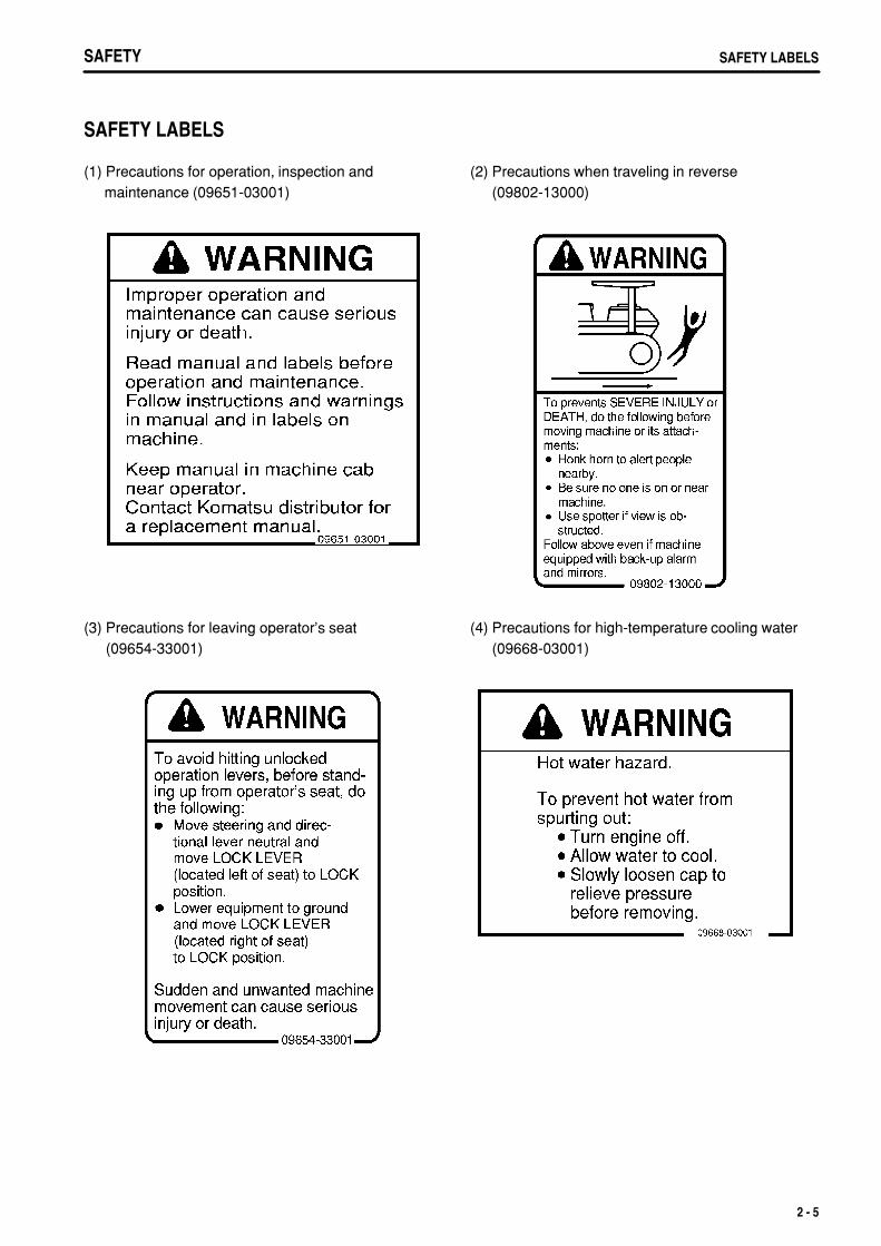
SAFETY LABELS
(1) Precautions for operation, inspection and maintenance (09651-03001)
(2) Precautions when traveling in reverse(09802-13000)
(3) Precautions for leaving operator's seat(09654-33001)
(4) Precautions for high-temperature cooling water(09668-03001)
2 - 5

.
SAFETYSAFETY LABELS
(5) Precautions for high-temperature hydraulic oil(09653-03001)
(6) Precautions for check and adjust track tension(195-98-22931)
(7) Precautions for handling electric wires(09808-03000)
(8) Caution for engine running (09667-03001)
2 - 6

.
SAFETY SAFETY LABELS
(9) Precautions for handling accumulator(09659-53000)
(10) Precautions for use of seat belt (195-98-12940)
(11) Caution for approach when machine moving(09812-03000)
(12) Warning for ROPS (09620-30201)
2 - 7

.
SAFETYSAFETY LABELS
(13) Warning for battery (09664-30082)
2 - 8

.
SAFETY GENERAL PRECAUTIONS
GENERAL PRECAUTIONS
SAFETY RULESOnly trained and authorized personnel can operate and maintain the machine.Follow all safety rules, precautions and instructions in this manual when operating or performing maintenance onthe machine.If you are not feeling well, or if you are under the influence of alcohol or medication, your ability to safely operateor repair your machine may be severely impaired, putting yourself and everyone else on your job site in danger.When working with another operator or with the person on the worksite traffic duty, discuss the content of theoperation beforehand and use the determined signals when carrying out the operation.
IF ABNORMALITIES ARE FOUNDIf you find any problems in the machine during operation or maintenance (noise, vibration, smell, incorrect gauges,smoke, oil leakage, etc., or any abnormal display on the warning devices or monitor), report to the person in chargeand have the necessary action taken. Do not operate the machine until the problem has been corrected.
CLOTHING AND PERSONAL PROTECTIVE ITEMSDo not wear loose clothing and accessories. There is a hazard that they may catch on control levers or otherprotruding parts.If you have long hair and it hangs out from your hard hat, thereis a hazard that it may get caught up in the machine, so tie yourhair up and be careful not to let it get caught.Always wear a hard hat and safety shoes. If the nature of thework requires it, wear safety glasses, mask, gloves, ear plugs,and safety belt when operating or maintaining the machine.Check that all protective equipment functions properly beforeusing it.
FIRE EXTINGUISHER AND FIRST AID KITAlways follow the precautions below to prepare for action if any injury or fire should occur.
Be sure that fire extinguishers have been provided and read thelabels to ensure that you know how to use them in emergencies.Carry out periodic inspection and maintenance to ensure thatthe fire extinguisher can always be used.Provide a first aid kit in the storage point. Carry out periodicchecks and add to the contents if necessary.
SAFETY FEATURESBe sure that all guards, covers and mirrors are in their proper position. Have guards and covers repairedimmediately if they are damaged.Understand the method of use of safety features and use them properly.Never remove any safety features. Always keep them in good operating condition.
2 - 9

.
SAFETYGENERAL PRECAUTIONS
KEEP MACHINE CLEANIf water gets into the electrical system, there is a hazard that it will cause malfunctions or misoperation. Do notuse water or steam to wash the electrical system (sensors, connectors).If inspection and maintenance is carried out when the machineis still dirty with mud or oil, there is a hazard that you will slip andfall, or that dirt or mud will get into your eyes. Always keep themachine clean.
INSIDE OPERATOR'S COMPARTMENTWhen entering the operator's compartment, always remove all mud and oil from the soles of your shoes.If you operate the pedal with mud or oil affixed to your shoes, your foot may slip and this may cause a seriousaccident.Do not leave parts or tools lying around the operator's compartment.Do not stick suction pads to the window glass. Suction pads act as a lens and may cause fire.Do not use cellular telephones inside the operator's compartment when driving or operating the machine.Never bring any dangerous objects such as flammable or explosive items into the operator's compartment.
ALWAYS APPLY LOCK WHEN LEAVING OPERATOR'S SEATBefore standing up from the operator's seat, lower the workequipment completely to the ground, set work equipment locklever and parking brake lever securely to the LOCK position (L),then stop the engine.If you accidentally touch the levers when they are not locked,there is a hazard that the machine may suddenly move andcause serious injury or property damage.
When leaving the machine, always lower the work equipmentcompletely to the ground, set work equipment lock lever andparking brake lever securely to the LOCK position (L), then stopthe engine. Use the key to lock all the equipment. Alwaysremove the key, take it with you, and keep it in the specifiedplace.
2 - 10
.
SAFETY GENERAL PRECAUTIONS
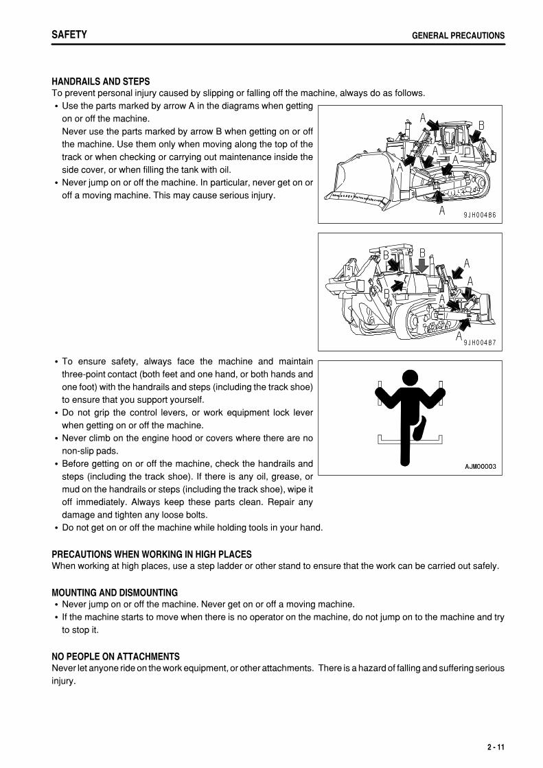
HANDRAILS AND STEPSTo prevent personal injury caused by slipping or falling off the machine, always do as follows.
Use the parts marked by arrow A in the diagrams when gettingon or off the machine.Never use the parts marked by arrow B when getting on or offthe machine. Use them only when moving along the top of thetrack or when checking or carrying out maintenance inside theside cover, or when filling the tank with oil.Never jump on or off the machine. In particular, never get on oroff a moving machine. This may cause serious injury.
To ensure safety, always face the machine and maintainthree-point contact (both feet and one hand, or both hands andone foot) with the handrails and steps (including the track shoe)to ensure that you support yourself.Do not grip the control levers, or work equipment lock leverwhen getting on or off the machine.Never climb on the engine hood or covers where there are nonon-slip pads.Before getting on or off the machine, check the handrails andsteps (including the track shoe). If there is any oil, grease, ormud on the handrails or steps (including the track shoe), wipe itoff immediately. Always keep these parts clean. Repair anydamage and tighten any loose bolts.Do not get on or off the machine while holding tools in your hand.
PRECAUTIONS WHEN WORKING IN HIGH PLACESWhen working at high places, use a step ladder or other stand to ensure that the work can be carried out safely.
MOUNTING AND DISMOUNTINGNever jump on or off the machine. Never get on or off a moving machine.If the machine starts to move when there is no operator on the machine, do not jump on to the machine and tryto stop it.
NO PEOPLE ON ATTACHMENTSNever let anyone ride on the work equipment, or other attachments. There is a hazard of falling and suffering seriousinjury.
2 - 11

.
SAFETYGENERAL PRECAUTIONS
CRUSHING OR CUTTING PREVENTIONThe clearance around the work equipment will change according to the movement of the link. If you get caught, thismay lead to serious personal injury. Do not allow anyone to approach any rotating or telescoping part.
2 - 12

.
SAFETY GENERAL PRECAUTIONS
PREVENTION OF BURNSHot coolant
To prevent burns from hot water or steam spurting out whenchecking or draining the coolant, wait for the water to cool to atemperature where it is possible to touch the radiator cap byhand before starting the operation. Even when the coolant hascooled down, loosen the cap slowly to relieve the pressureinside the radiator before removing the cap.
Hot oilTo prevent burns from hot oil spurting out when checking ordraining the oil, wait for the oil to cool to a temperature where itis possible to touch the cap or plug by hand before starting theoperation. Even when the oil has cooled down, loosen the capor plug slowly to relieve the internal pressure before removingthe cap or plug.
FIRE PREVENTIONFire caused by fuel or oilFuel, oil, antifreeze, and window washer liquid are particularlyflammable and can be hazardous. To prevent fire, alwaysobserve the following:
Do not smoke or use any flame near fuel or oil.Stop the engine before refueling.Do not leave the machine while adding fuel or oil.Tighten all fuel and oil caps securely.Do not spill fuel on overheated surfaces or on parts of theelectrical system.Use well-ventilated areas for adding or storing oil and fuel.Keep oil and fuel in the determined place and do not allowunauthorized persons to enter.After adding fuel or oil, wipe up any spilled fuel or oil.When carrying out grinding or welding work on the chassis,move any flammable materials to a safe place beforestarting.When washing parts with oil, use a non-flammable oil. Dieseloil and gasoline may catch fire, so do not use them.Put greasy rags and other flammable materials into a safecontainer to maintain safety at the work place.Do not weld or use a cutting torch to cut any pipes or tubesthat contain flammable liquids.
2 - 13

.
SAFETYGENERAL PRECAUTIONS
Fire caused by accumulation of flammable material.Prevention of fire around high-temperature parts or electrical partsRemove any flammable materials, such as dry leaves, chips, paper, or coal dust that are accumulated aroundthe engine, exhaust manifold, muffler, or battery.Prevention of fire spreading from outside machineTo prevent fire caused by sparks from fires, remove any flammable materials such as dry leaves, chips, paper,or coal dust that are accumulated near the cooling system (radiator, oil cooler) or inside the undercover.
Fire coming from electric wiringShort circuits in the electrical system can cause fire.
Always keep electric wiring connections clean and securely tightened.Check the wiring every day for looseness or damage. Tighten any loose connectors or wiring clamps. Repairor replace any damaged wiring.
Fire coming from hydraulic lineCheck that all the hose and tube clamps, guards, and cushions are securely fixed in position.If they are loose, they may vibrate during operation and rub against other parts. This may lead to damage to thehoses, and cause high-pressure oil to spurt out, leading to fire damage or serious injury.
Explosion caused by lighting equipmentWhen checking fuel, oil, battery electrolyte, window washer fluid, or coolant, always use lighting withanti-explosion specifications. If such lighting equipment is not used, there is danger of explosion that maycause serious injury.When taking the electrical power for the lighting from the machine itself, follow the instructions in this manual.
ACTION IF FIRE OCCURSIf a fire occurs, escape from the machine as follows.
Turn the start switch OFF to stop the engine.Use the handrails and steps to get off the machine.
WINDOW WASHER LIQUIDUse an ethyl alcohol base washer liquid.Methyl alcohol base washer liquid may irritate your eyes, so do not use it.
2 - 14

.
SAFETY GENERAL PRECAUTIONS
PRECAUTIONS WHEN USING ROPS (Roll Over Protective Structure)Install ROPS when working in places where there is danger offalling rocks, such as in mines and quarries, or in places wherethere is danger of rolling over.
If ROPS is installed, do not remove it when operating themachine.ROPS is installed to protect the operator when machine rollsover. When machine rolls over, ROPS supports its weight andabsorbs its impact energy.If ROPS is modified, its strength may lower. When modifying it,consult your Komatsu distributor.If ROPS is deformed by falling objects or by rolling over, its strength lowers and its design functions cannot bemaintained. In this case, be sure to ask your Komatsu distributor about repair method.
Even when the ROPS is installed, if you do not fasten your seat belt securely, it cannot protect you properly. Alwaysfasten your seat belt when operating the machine.
PRECAUTIONS FOR ATTACHMENTSWhen installing optional parts or attachments, there may be problems with safety or legal restrictions. Thereforecontact your Komatsu distributor for advice.Any injuries, accidents, product failures or other property damages resulting from the use of unauthorizedattachments or parts will not be the responsibility of Komatsu.When installing and using optional attachments, read the instruction manual for the attachment, and the generalinformation related to attachments in this manual.
CAB WINDOW GLASSESIf the cab glass on the work equipment side is broken, there is a hazard that the work equipment may contact theoperator's body directly. Stop operation immediately and replace the glass.
UNAUTHORIZED MODIFICATIONAny modification made without authorization from Komatsu can create hazards. Before making a modification,consult your Komatsu distributor.
Komatsu will not be responsible for any injuries, accidents, product failures or other property damages resultingfrom modifications made without authorization from Komatsu.
SAFETY AT WORKSITEBefore starting operations, thoroughly check the area for any unusual conditions that could be dangerous.
When carrying out operations near combustible materials such as thatched roofs, dry leaves or dry grass, thereis a hazard of fire, so be careful when operating.Check the terrain and condition of the ground at the worksite, and determine the safest method of operation. Donot operate where there is a hazard of landslides or falling rocks.
2 - 15

.
SAFETYGENERAL PRECAUTIONS SAFETYGENERAL PRECAUTIONS
If water lines, gas lines, or high-voltage electrical lines may beburied under the worksite, contact each utility and identify theirlocations. Be careful not to sever or damage any of these lines.Take necessary measures to prevent any unauthorized personfrom entering the operating area.In particular, if you need to operate on a road, protect pedestrianand cars by designating a person for worksite traffic duty or byinstalling fences around the worksite.When traveling or operating in shallow water or on soft ground,check the shape and condition of the bedrock, and the depthand speed of flow of the water before starting operations.
WORKING ON LOOSE GROUNDAvoid traveling or operating your machine too close to the edge of cliffs, overhangs, and deep ditches. Theground may be weak in such areas. If the ground should collapse under the weight or vibration of the machine,there is a hazard that the machine may fall or tip over. Remember that the soil after heavy rain or blasting or afterearthquakes is weak in these areas.When working on embankments or near excavated ditches, there is a hazard that the weight and vibration of themachine will cause the soil to collapse. Before starting operations, take steps to ensure that the ground is safeand to prevent the machine from rolling over or falling.
2 - 16

.
SAFETY GENERAL PRECAUTIONS
DO NOT GO CLOSE TO HIGH-VOLTAGE CABLESDo not travel or operate the machine near electric cables. There isa hazard of electric shock, which may cause serious personalinjury or death. On jobsites where the machine may go close toelectric cables, always do as follows.
Before starting work near electric cables, inform the local powercompany of the work to be performed, and ask them to take thenecessary action.
Voltage of Cables Safety Distance100 V - 200 V Over 2 m (7 ft)
6,600 V Over 2 m (7 ft)
22,000 V Over 3 m (10 ft)
66,000 V Over 4 m (14 ft)
154,000 V Over 5 m (17 ft)
187,000 V Over 6 m (20 ft)
275,000 V Over 7 m (23 ft)
500,000 V Over 11 m (36 ft)
Even going close to high-voltage cables can cause electricshock, which may cause serious burns or even death. Alwaysmaintain a safe distance (see the table on the right) between themachine and the electric cable. Check with the local powercompany about safe operating procedure before startingoperations.To prepare for any possible emergencies, wear rubber shoesand gloves. Lay a rubber sheet on top of the seat, and be carefulnot to touch the chassis with any exposed part of your body.Use a signalman to give warning if the machine approaches tooclose to the electric cables.When carrying out operations near high voltage cables, do notlet anyone near the machine.If the machine should come too close or touch the electric cable,to prevent electric shock, the operator should not leave theoperator's compartment until it has been confirmed that theelectricity has been shut off.Also, do not let anyone near the machine.
ENSURE GOOD VISIBILITYCheck for any persons or obstacles in the area around the machine and check the conditions of the jobsite toensure that operations and travel can be carried out safely. Always do as follows.
Position a signalman if there are areas at the rear of the machine where the visibility is not good.When working in dark places, turn on the working lamp and front lamps installed to the machine, and set upadditional lighting in the work area if necessary.Stop operations if the visibility is poor, such as in mist, snow, rain, or dust.
VENTILATION FOR ENCLOSED AREASExhaust fumes from the engine can kill.
If it is necessary to start the engine within an enclosed area, orwhen handling fuel, flushing oil, or paint, open the doors andwindows to ensure that adequate ventilation is provided toprevent gas poisoning.
2 - 17

.
SAFETYGENERAL PRECAUTIONS
CHECKING SIGNALMAN'S SIGNALS AND SIGNSSet up signs to inform of road shoulders and soft ground. If the visibility is not good, position a signalman ifnecessary. Operators should pay careful attention to the signs and follow the instructions from the signalman.Only one signalman should give signals.Make sure that all workers understand the meaning of all signals and signs before starting work.
BE CAREFUL ABOUT ASBESTOS DUSTAsbestos dust in the air can cause lung cancer if it is inhaled. Thereis danger of inhaling asbestos when working on jobsites handlingdemolition work or work handling industrial waste. Always observethe following.
Spray water to keep down the dust when cleaning. Do not usecompressed air for cleaning.If there is danger that there may be asbestos dust in the air,always operate the machine from an upwind position. Allworkers should use an approved respirator.Do not allow other persons to approach during the operation.Always observe the rules and regulations for the work site andenvironmental standards.
This machine does not use asbestos, but there is a danger thatimitation parts may contain asbestos, so always use genuineKomatsu parts.
2 - 18

.
SAFETY PRECAUTIONS FOR OPERATION
PRECAUTIONS FOR OPERATION
BEFORE STARTING ENGINEIf there is a warning tag hanging from the work equipment controllever, do not start the engine or touch the levers.
CHECKS BEFORE STARTING ENGINECarry out the following checks before starting the engine at the beginning of the day's work.
Completely remove all flammable materials accumulated around the engine and battery, and remove any dirtfrom the windows, mirrors, handrails and steps.Remove all dirt from the surface of the lens of the front lamps and working lamps, and check that they light upcorrectly.Check the coolant level, fuel level, and oil level in engine oil pan, check for clogging of the air cleaner, and checkfor damage to the electric wiring.Adjust the operator's seat to a position where it is easy to carry out operations, and check that there is no damageor wear to the seat belt or mounting clamps.Check the operation of the instruments and gauges, check the angle of the mirror, and check that the controllevers are all at the Neutral position.When starting the engine, check that the parking brake lever and work equipment lock lever are at the LOCKposition.Adjust the mirrors so that you can get a good rear-view from the operator's seat.For the details of adjustment, see "ADJUST MIRROR (PAGE 3-83)".Check that there are no persons or obstacles above, below, or in the area around the machine.
PRECAUTIONS WHEN STARTINGWhen starting the engine, sound the horn as a warning.Start and operate the machine only while seated.Do not allow anyone apart from the operator to ride on the machine.Do not short circuit the starting motor circuit to start the engine. Short circuit can cause fire.
2 - 19

.
SAFETYPRECAUTIONS FOR OPERATION
PRECAUTIONS IN COLD AREASCarry out the warming-up operation thoroughly. If the machine is not thoroughly warmed up before the controllevers are operated, the reaction of the machine will be slow, and this may lead to unexpected accidents.If the battery electrolyte is frozen, do not charge the battery or start the engine with a different power source.There is a hazard that this will ignite the battery and cause the battery to explode.Before charging or starting the engine with a different power source, melt the battery electrolyte and check thatthere is no leakage of electrolyte before starting.
2 - 20

.
SAFETY PRECAUTIONS FOR OPERATION
OPERATION
CHECKS BEFORE OPERATIONWhen carrying out the checks, move the machine to a wide area where there are no obstructions, and operateslowly. Do not allow anyone near the machine.
Always fasten your seat belt.Check the operation of travel, steering and brake systems, andwork equipment control system. Check for any problem in the sound of the machine, vibration,heat, smell, or gauges; check also that there is no leakage of oilor fuel.If any problem is found, carry out repairs immediately.
PRECAUTIONS FOR MOVING MACHINE FORWARD OR IN REVERSEBefore travelling, check again that there is no one in the surrounding area, and that there are no obstacles.Before travelling, sound the horn to warn people in the area.Always operate the machine only when seated.Do not allow anyone apart from the operator to ride on the machine.Check that the backup alarm (alarm buzzer when machine travels in reverse) works properly.Always lock the door and windows of the operator's compartment in position (open or closed).On jobsites where there is a hazard of flying objects or of objects entering the operator's compartment, check thatthe door and windows are securely closed.If there is an area to the rear of the machine where the visibility is obstructed, use a flagman. Be extremely carefulnot to hit anything and drive the machine slowly.
Always be sure to carry out the above precautions even when themachine is equipped with mirrors.
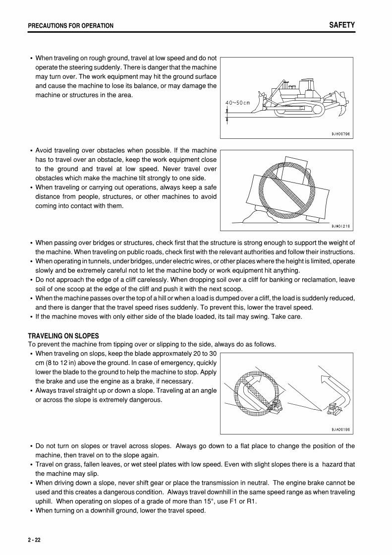
PRECAUTIONS WHEN TRAVELINGNever turn the starting switch to the OFF position when traveling. It is dangerous if the engine stops when themachine is traveling. When the engine is off, it is impossible to operate the steering. Apply the brakes and stopthe machine immediately, if the engine stops.When traveling on flat ground, keep the work equipment 40 to 50 cm (16 to 20 in) high above the ground.
2 - 21
.
SAFETYPRECAUTIONS FOR OPERATION SAFETYPRECAUTIONS FOR OPERATION
When traveling on rough ground, travel at low speed and do notoperate the steering suddenly. There is danger that the machinemay turn over. The work equipment may hit the ground surfaceand cause the machine to lose its balance, or may damage themachine or structures in the area.
Avoid traveling over obstacles when possible. If the machinehas to travel over an obstacle, keep the work equipment closeto the ground and travel at low speed. Never travel overobstacles which make the machine tilt strongly to one side.When traveling or carrying out operations, always keep a safedistance from people, structures, or other machines to avoidcoming into contact with them.
When passing over bridges or structures, check first that the structure is strong enough to support the weight ofthe machine. When traveling on public roads, check first with the relevant authorities and follow their instructions.When operating in tunnels, under bridges, under electric wires, or other places where the height is limited, operateslowly and be extremely careful not to let the machine body or work equipment hit anything.Do not approach the edge of a cliff carelessly. When dropping soil over a cliff for banking or reclamation, leavesoil of one scoop at the edge of the cliff and push it with the next scoop.When the machine passes over the top of a hill or when a load is dumped over a cliff, the load is suddenly reduced,and there is danger that the travel speed rises suddenly. To prevent this, lower the travel speed.If the machine moves with only either side of the blade loaded, its tail may swing. Take care.
TRAVELING ON SLOPESTo prevent the machine from tipping over or slipping to the side, always do as follows.
When traveling on slops, keep the blade approxmately 20 to 30cm (8 to 12 in) above the ground. In case of emergency, quicklylower the blade to the ground to help the machine to stop. Applythe brake and use the engine as a brake, if necessary.Always travel straight up or down a slope. Traveling at an angleor across the slope is extremely dangerous.
Do not turn on slopes or travel across slopes. Always go down to a flat place to change the position of themachine, then travel on to the slope again.Travel on grass, fallen leaves, or wet steel plates with low speed. Even with slight slopes there is a hazard thatthe machine may slip.When driving down a slope, never shift gear or place the transmission in neutral. The engine brake cannot beused and this creates a dangerous condition. Always travel downhill in the same speed range as when travelinguphill. When operating on slopes of a grade of more than 15°, use F1 or R1.When turning on a downhill ground, lower the travel speed.
2 - 22

.
SAFETY PRECAUTIONS FOR OPERATION
PROHIBITED OPERATIONSTo make it easier to escape if there is any problem, set the tracks at right angles to the road shoulder or cliff withthe sprocket at the rear when carrying out operations.When operating the machine, take care that it will not exceed its performance values such as stability, maximumusing load, etc. to prevent rolling of the machine caused by an overload and disasters caused by breakage of thework equipment.
USING BRAKESWhen the machine is traveling, do not rest your foot on the brake pedal. If you travel with your foot resting on thepedal, the brake will always be applied, and this will cause the brakes to overheat and fail.Do not depress the brake pedal repeatedly if not necessary. If this is neglected, the brake will be overheated andwill not work when required.When traveling downhill, use the braking force of the engine.
OPERATE CAREFULLY ON SNOWSnow-covered or frozen surfaces are slippery, so be extremely careful when traveling or operating the machine,and do not operate the levers suddenly. Even a slight slope may cause the machine to slip, so be particularlycareful when working on slopes.With frozen ground surfaces, the ground becomes soft when the temperature rises, and this may cause themachine to tip over or make it impossible for the machine to escape.If the machine enters deep snow, there is a hazard that it may tip over or become buried in the snow. Be carefulnot to leave the road shoulder or to get trapped in a snow drift.When clearing snow, the road shoulder and objects placed beside the road are buried in the snow and cannot beseen. There is a hazard of the machine tipping over or hitting covered objects, so always carry out operationscarefully.When traveling on snow-covered slopes, never apply the brakes suddenly. Reduce the speed and use the engineas a brake while appling the foot brake intermittently (depress the brake intermittently several times). Ifnecessary, lower the blade to the ground to stop the machine.
PARKING MACHINEPark the machine on level ground where there is no danger offalling rocks or landslides, or of flooding if the land is low, andlower the work equipment to the ground.If it is necessary to park the machine on a slope, set the blocks(1) under the tracks to prevent the machine from moving, thendig the Point (2) of work equipment into the ground.After stopping the engine, operate the right work equipmentcontrol lever several times to the RAISE and LOWER positionsto release the remaining pressure in the hydraulic circuit.
When leaving the machine, set the work equipment lock leverand parking brake lever to the LOCK position (L), stop theengine, and use the key to lock all the equipment. Alwaysremove the key and take it with you.Work equipment posture: See "PARKING MACHINE (PAGE3-109)".Locks: See "LOCKING (PAGE 3-111)".Always close the door of the operator's compartment.
2 - 23

.
SAFETYPRECAUTIONS FOR OPERATION
TRANSPORTATIONThe machine can be divided into parts for transportation, so when transportating the machine, please contact yourKomatsu distributor to have the work carried out.
LOADING AND UNLOADINGWhen loading or unloading the machine, mistaken operation may bring the hazard of the machine tipping over orfalling, so particular care is necessary. Always do as follows.
Perform loading and unloading on firm, level ground only.Maintain a safe distance from the edge of the road or cliff.Never use the work equipment to load or unload the machine.There is danger that the machine may fall or tip over.Always use ramps of adequate strength. Be sure that the rampsare wide, long, and thick enough to provide a safe loading slope.Take suitable steps to prevent the ramps from moving out ofposition or coming off.
(1)(2)(3)(4)
BlocksRampCenterline of trailerAngle of ramps: Max. 15°
Be sure the ramp surface is clean and free of grease, oil, ice and loose materials. Remove dirt frommachine-tracks. On a rainy day, in particular, be extremely careful since the ramp surface is slippery.Run the engine at low speed and travel slowly.When on the ramps, do not operate any lever except for the travel lever.Never correct your steering on the ramps. If necessary, drive off the ramps, correct the direction, then enter theramps again.The center of gravity of the machine will change suddenly at the joint between the ramps and the track or trailer,and there is danger of the machine losing its balance. Travel slowly over this point.When loading or unloading to an embankment or platform, make sure that it has suitable width, strength, andgrade.For machines equipped with a cab, always lock the door after boarding the machine. If this is not done, the doormay suddenly open during transportation.Refer to "TRANSPORTATION (PAGE 3-131)".
SHIPPINGWhen shipping the machine on a trailer, do as follows.
The weight, transportation height, and overall length of the machine differ according to the work equipment, sobe sure to confirm the dimensions.When passing over bridges or structures on private land, check first that the structure is strong enough to supportthe weight of the machine. When traveling on public roads, check first with the relevant authorities and follow theirinstructions.For details of the shipping procedure, see "TRANSPORTATION (PAGE 3-131)" in the OPERATION section.
BATTERY
BATTERY HAZARD PREVENTIONBattery electrolyte contains sulphuric acid, and batteries generate flammable hydrogen gas, which may explode.Mistaken handling can lead to serious injury or fire. For this reason, always observe the following precautions.
2 - 24

.
SAFETY PRECAUTIONS FOR OPERATION
When the battery electrolyte is below LOWER LEVEL, don't either use or charge the battery. Otherwise, that maycause explosion. Always carry out periodic checks of the battery electrolyte, and add distilled water up to UPPERLEVEL.For the method of checking the battery electrolyte, see "CHECK LEVEL OF BATTERY ELECTROLYTE (PAGE4-52)".When working with batteries, always wear safety glasses and rubber gloves.Never smoke or use any flame near the battery.
If you spill acid on your clothes or skin, immediately flush thearea with large amount of water.If acid gets into your eyes, flush them immediately with largeamount of water and seek medical attention.
Before working with batteries, turn the starting switch to the OFF position.
As there is a hazard that sparks will be generated, always do as follows.Do not let tools or other metal objects make any contact between the battery terminals. Do not leave tools or othermetal objects lying around near the battery.When disconnecting the battery terminals, wait for approx. one minute after turning off the engine starting switchkey, and be sure to disconnect the grounding terminal (negative (-) terminal) first. Conversely, when connectingthem, begin with the positive (+) terminal and then the grounding (-) terminal. Make sure that all the terminals areconnected securely.Tighten the battery terminals securely.Flammable hydrogen gas is generated when the battery is charged, so remove the battery from the chassis, takeit to a well-ventilated place, and remove the battery caps before charging it.Tighten the battery caps securely.Install the battery securely to the determined place.
STARTING WITH BOOSTER CABLEIf any mistake is made in the method of connecting the booster cables, it may cause the battery to explode, soalways do as follows.
2 - 25

.
SAFETYPRECAUTIONS FOR OPERATION SAFETYPRECAUTIONS FOR OPERATION
When starting with a booster cable, carry out the startingoperation with two workers (one worker sitting in the operator'sseat and the other working with the battery).When starting from another machine, do not allow the twomachines to touch.
When connecting the booster cables, turn the starting switchOFF position for both the normal machine and problemmachine. There is a hazard that the machine will move when thepower is connected.Be sure to connect the positive (+) cable first when installing thebooster cables. Disconnect the negative (-) cable (ground side)first when removing them.
When removing the booster cables, be careful not to let the booster cable clips touch each other or to let the clipstouch the machine.Always wear safety glasses and rubber gloves when starting the engine with booster cables.When connecting a normal machine to a problem machine with booster cables, always use a normal machinewith the same battery voltage as the problem machine.For the procedure of starting the engine with booster cables, see "STARTING ENGINE WITH BOOSTER CABLE(PAGE 3-142)".
TOWING
WHEN TOWINGSerious injury or death could result if a disabled machine is towed incorrectly or if there is a mistake in the selectionor inspection of the wire rope.For towing, see "METHOD OF TOWING MACHINE (PAGE 3-141)".
Always check that the wire rope used for towing has ample strength for the weight of the machine being towed.Never use a wire rope which has cut strands (A), reduceddiameter (B), or kinks (C). There is danger that the rope maybreak during the towing operation.
Always wear leather gloves when handling wire rope.Never tow a machine on a slope.During the towing operation, never stand between the towing machine and the machine being towed.Operate the machine slowly and be careful not to apply any sudden load to the wire rope.
2 - 26

.
SAFETY PRECAUTIONS FOR MAINTENANCE
PRECAUTIONS FOR MAINTENANCE
WARNING TAGAlways attach the "DO NOT OPERATE" warning tag to the workequipment control lever in the operator's cab to alert others thatyou are performing service or maintenance on the machine.Attach additional warning tags around the machine if necessary.Warning tag Part No. 09963-03001Keep the tag in the operation manual pocket.If others start the engine, or touch or operate the workequipment control lever while you are performing service ormaintenance, you could suffer serious injury or propertydamage.
KEEP WORK PLACE CLEAN AND TIDYDo not leave hammers or other tools lying around in the work place. Wipe up all grease, oil, or other substancesthat will cause you to slip. Always keep the work place clean and tidy to enable you to carry out operations safely.If the work place is not kept clean and tidy, there is the danger that you will trip, slip, or fall over and injure yourself.
APPOINT LEADER WHEN WORKING WITH OTHERSWhen repairing the machine or when removing and installing the work equipment, appoint a leader and follow hisinstructions during the operation.
STOP ENGINE BEFORE CARRYING OUT INSPECTION AND MAINTENANCEStop the machine on firm, level ground.Select a place where there is no hazard of landslides, fallingrocks, or flooding.Lower the work equipment completely to the ground and stopthe engine.
2 - 27

.
SAFETYPRECAUTIONS FOR MAINTENANCE SAFETYPRECAUTIONS FOR MAINTENANCE
After stopping the engine, operate the work equipment controllever to the RAISE and LOWER positions 2 or 3 times to releasethe pressure remaining in the hydraulic circuit, then set the workequipment lock lever and Parking brake lever to LOCK position(L).
Check that the battery relay is off and main power is notconducted. (Wait for approx. one minute after turning off theengine starting switch key and press the horn switch. If the horndoes not sound, it is not activated.)Put blocks (1) under the track to prevent the machine frommoving.
TWO WORKERS FOR MAINTENANCE WHEN ENGINE IS RUNNINGTo prevent personal injury, do not carry out maintenance with the engine running. If maintenance must be carriedout with the engine running, carry out the operation with at least two workers and do as follows.
One worker must always sit in the operator's seat and be readyto stop the engine at any time. All workers must maintaincontact with the other workers.Place the parking brake lever and work equipment lock lever atthe LOCK position (L) to prevent the work equipment frommoving.Do not touch any control levers. If any control lever must beoperated, give a signal to the other workers to warn them tomove to a safe place.
When carrying out operations near the fan, fan belt, or otherrotating parts, there is a hazard of being caught in the parts, sobe careful not to come close.Never drop or insert tools or other objects into the fan or fan belt.Parts may break or be sent flying.
2 - 28

.
SAFETY PRECAUTIONS FOR MAINTENANCE
PROPER TOOLSUse only tools suited to the task and be sure to use the toolscorrectly. Using damaged, low quality, faulty, makeshift tools orimproper use of the tools could cause serious personal injury.
HANDLING ACCUMULATOROn machines equipped with an accumulator,for a short time after the engine is stopped,if the blade control leveris moved to the LOWER position,the work equipment will move down under its own weight.After stopping the engine,always place the work equipment lock lever and parking brake lever in the LOCKpositionWhen releasing the pressure inside the work equipment circuit on machines equipped with an accumulator, followthe procedure given in the following section.Method of releasing pressure : See "ACCUMULATOR, HANDLING (PAGE 3-67)".
The accumulator is charged with high-pressure nitrogen gas.When handling the accumulator, careless procedure may causean explosion which could lead to serious injury or propertydamage. For this reason, always observe the followingprecautions.
Do not disassemble the accumulator.Do not bring it near flame or dispose of it in fire.Do not make holes in it, weld it, or use a cutting torch.Do not hit or roll the accumulator, or subject it to any impact.When disposing of the accumulator, the gas must be released.Please contact your Komatsu distributor to have this workperformed.
PERSONNELDo not allow any unauthorized personnel into the area when servicing the machine. If necessary, employ a guard.
ATTACHMENTSAppoint a leader before starting removal or installationoperations for attachments.Place attachments that have been removed from the machine ina stable condition so that they do not fall. And take steps toprevent unauthorized persons from entering the storage area.
2 - 29

.
SAFETYPRECAUTIONS FOR MAINTENANCE
WORK UNDER THE MACHINEIf it is necessary to go under the work equipment or the machineto carry out service and maintenance, support the workequipment and machine securely with blocks and stands strongenough to support the weight of the work equipment andmachine.It is extremely dangerous to work under the machine if the trackshoes are lifted off the ground and the machine is supportedonly with the work equipment. If any of the control levers istouched by accident, or there is damage occurring to thehydraulic piping, the work equipment or the machine willsuddenly drop. This is extremely dangerous. Never work underthe work equipment or the machine.
NOISEWhen carrying out maintenance of the engine and you are exposed to noise for long periods of time, wear ear coversor ear plugs while working.If the noise from the machine is too loud, it may cause temporary or permanent hearing problems.
PRECAUTIONS WHEN USING HAMMERWhen using a hammer, pins may fly out or metal particles may be scattered. This may lead to serious injury. Alwaysdo as follows.
If hard metal parts such as pins, bucket teeth, cutting edges, orbearings are hit with a hammer, there is a hazard that piecesmight be scattered and cause serious personal injury or death.Always wear safety glasses and gloves.When hitting pins or bucket teeth, there is a hazard that brokenpieces might be sent flying and injure people in the surroundingarea. Always check that there is no one in the surrounding area.There is a hazard that the pin hit with strong force may fly outand injure people in the surrounding area.
REPAIR WELDINGWelding operations must always be carried out by a qualified welder and in a place equipped with proper equipment.There is a hazard of gas, fire, or electrocution when carrying out welding, so never allow any unqualified personnelto carry out welding.
REMOVING BATTERY TERMINALWhen repairing or welding the electrical system, wait for approx. one minute after turning off the engine startingswitch key, and then disconnect the negative (-) terminal of the battery to stop the flow of electricity.
2 - 30

.
SAFETY PRECAUTIONS FOR MAINTENANCE
PRECAUTIONS WHEN USING HIGH-PRESSURE GREASE TO ADJUST TRACK TENSIONGrease is pumped into the track tension adjustment systemunder high pressure. If the specified procedure for maintenanceis not followed when making adjustment, grease drain valve (1)may fly out and cause serious injury or damage.
When loosening grease drain valve (1) to loosen track tension,never loosen it more than one turn. In doing so, loosen the valveslowly.Never put your face, hands, feet, or any other part of your bodydirectly in front of grease drain valve (1).
DO NOT DISASSEMBLE RECOIL SPRINGNever attempt to disassemble the recoils spring assembly. Itcontains a spring under high pressure which serves as a shockabsorber for the idler. If it is disassembled by mistake, the springwill fly out and cause serious injury. When it becomes necessaryto disassemble it, ask your Komatsu distributor to do the work.
PRECAUTION WITH HIGH-PRESSURE OILThe hydraulic system is always under internal pressure. When inspecting or replacing piping or hoses, alwayscheck that the pressure in the hydraulic circuit has been released. If the circuit is still under pressure, it will lead toserious personal injury, so always do as follows.
Do not carry out inspection or replacement work when the hydraulic system is under pressure.If there is any leakage from the piping or hoses, the surrounding area will be wet, so check for cracks in the pipingand hoses and for swelling in the hoses.When carry out inspection, wear safety glasses and leather gloves.
2 - 31

.
SAFETYPRECAUTIONS FOR MAINTENANCE SAFETYPRECAUTIONS FOR MAINTENANCE
There is a hazard that high-pressure oil leaking from small holesmay penetrate your skin or cause blindness if it contacts youreyes directly. If you are hit by a jet of high-pressureoil and sufferinjury to your skin or eyes, wash the place with clean water, andconsult a doctor immediately for medical attention.
HANDLING HIGH-PRESSURE HOSESIf oil or fuel leaks from high-pressure hoses, it may cause fire or defective operation, which may lead to seriousinjury. If any loose bolts are found, stop work and tighten to the specified torque. If any damaged hoses are found,stop operations immediately and contact your Komatsu distributor.
Replace the hose if any of the following problems are found.Damaged or leaking hydraulic fitting.Frayed or cut covering or exposed reinforcement wire layer.Covering swollen in places.Twisted or crushed movable portion.Foreign material embedded in covering.
WASTE MATERIALTo prevent pollution, pay careful attention to the method of disposing of waste materials.
Always put oil drained from your machine in containers. Neverdrain oil directly onto the ground or dump into the sewagesystem, rivers, the sea, or lakes.Obey appropriate laws and regulations when disposing ofharmful objects such as oil, fuel, coolant, solvent, filters, andbatteries.
MAINTENANCE FOR AIR CONDITIONERIf air conditioner refrigerant gets into your eyes, it may cause blindness; if it touches your skin, it may cause frostbite.Never touch refrigerant.
COMPRESSED AIRWhen carrying out cleaning with compressed air, there is a hazard of serious injury caused by flying particles.When using compressed air to clean elements or the radiator, always wear safety glasses, dust mask, gloves,and other protective equipment.
PERIODIC REPLACEMENT OF SAFETY CRITICAL PARTSFor using the machine safely for an extended period of time, replace safety-critical parts like hoses and seat beltsperiodically.Replacement of safety-critical parts: See "PERIODIC REPLACEMENT OF SAFETY CRITICAL PARTS (PAGE
4-15)".
2 - 32

.
SAFETY PRECAUTIONS FOR MAINTENANCE
The material of these components naturally changes over time, and repeated use causes deterioration, wear, andfatigue. As a result, there is a hazard that these components may fail and cause serious injury or death. It isdifficult to judge the remaining life of these components from external inspection or the feeling when operating,so always replace them at the specified interval.Replace or repair safety-critical parts if any defect is found, even when they have not reached the specifiedreplacement time.
2 - 33

.

.
3 - 1

.
OPERATIONGENERAL VIEW
GENERAL VIEW
GENERAL VIEW OF MACHINE
(1)(2)(3)(4)(5)
BladeBlade lift cylinderCabFuel tankRipper
(6)(7)(8)(9)(10)
SprocketTrack frameFrameTrack shoeROPS
3 - 2

.
OPERATION GENERAL VIEW
GENERAL VIEW OF CONTROLS AND GAUGES
(1) Parking lever(2) Safety lock lever(3) Cigarette lighter(4) Fuel control dial(5) Joystick (Steering, directional and gear shift lever)(6) Additional heater switch (if equipped)(7) Head lamp, working lamp switch(8) Rear lamp switch(9) Air conditioner panel or heater panel(10) Display panel A (Speed range, Engine speed)(11) Auto shift down switch
(12) Starting switch(13) Information switch(14) Buzzer cancel switch(15) Brake pedal(16) Deceleration pedal(17) Blade control lever(18) Horn switch(19) Ripper control lever(20) Pin puller control switch (if equipped)(21) Wiper switch(22) Room lamp switch
3 - 3
.
OPERATIONGENERAL VIEW
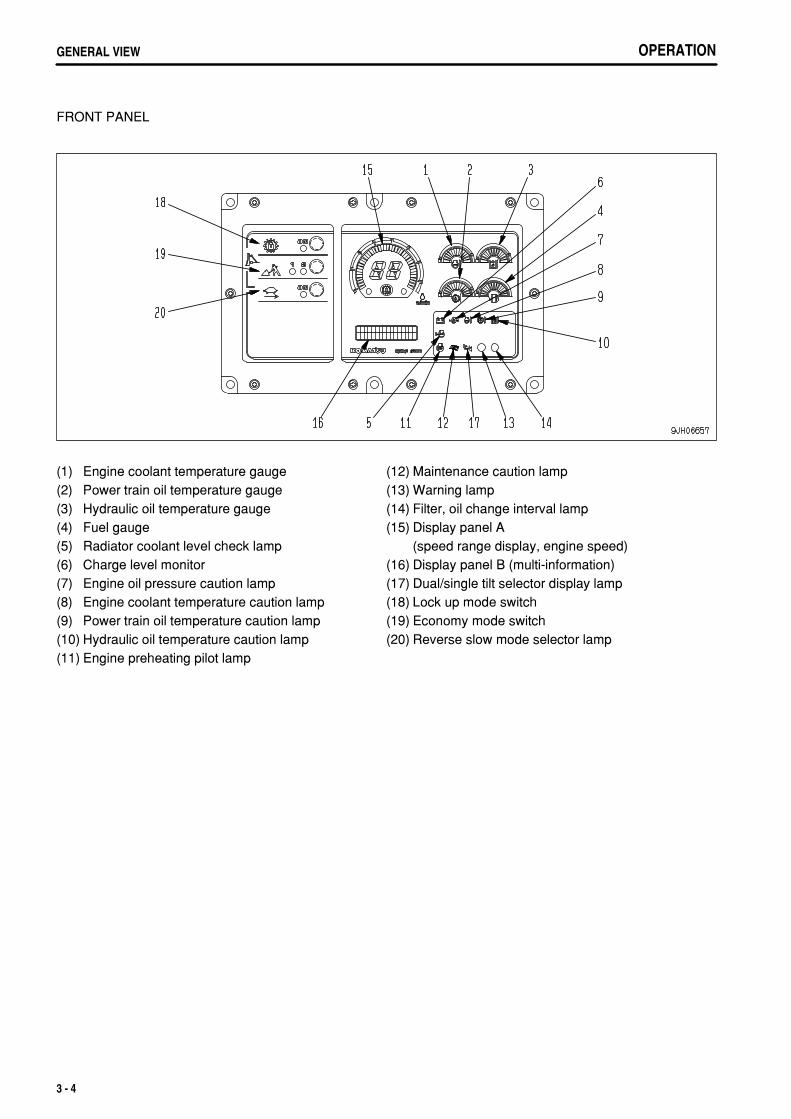
FRONT PANEL
(1)(2)(3)(4)(5)(6)(7)(8)(9)(10)(11)
Engine coolant temperature gaugePower train oil temperature gaugeHydraulic oil temperature gaugeFuel gaugeRadiator coolant level check lampCharge level monitorEngine oil pressure caution lampEngine coolant temperature caution lampPower train oil temperature caution lampHydraulic oil temperature caution lampEngine preheating pilot lamp
(12)(13)(14)(15)
(16)(17)(18)(19)(20)
Maintenance caution lampWarning lampFilter, oil change interval lampDisplay panel A (speed range display, engine speed)Display panel B (multi-information)Dual/single tilt selector display lampLock up mode switchEconomy mode switchReverse slow mode selector lamp
3 - 4

.
OPERATION EXPLANATION OF COMPONENTS
EXPLANATION OF COMPONENTSThe following is an explanation of devices needed for operating the machine.To perform suitable operations correctly and safely, it is important to completely understand methods of operatingthe equipment, and the meanings of the displays.
FRONT PANEL
(A)(B)(C)(D)
Check monitor groupCaution monitor groupEmergency caution itemsMeter and indicator group
(E)(F)(G)
Mode selection switch groupSwitchesLamps
3 - 5

.
OPERATIONEXPLANATION OF COMPONENTS
A: Check monitor group (for details, see "CHECK MONITOR GROUP (PAGE 3-7)")Before the engine is started, the basic items among the check before starting items that must be checked aredisplayed.If there is any abnormality, the caution lamp for the location of the abnormality flashes.
NOTICEWhen carrying out checks before starting, do not simply rely on the monitor. Always refer to the periodic maintenance items or"OPERATION (PAGE 3-70)" to carry out the checks.
B: Caution monitor group (See "CAUTION MONITOR GROUP (PAGE 3-9)")
CAUTIONIf the caution lamp for any of these items flashes, check and repair the appropriate item as soon as possible.
These are items which need to be observed when the engine is running. If any problem occurs, the item needingimmediate repair is displayed. If there is any problem, the problem location on the caution lamp will flash.
C: Emergency caution items (for details, see "EMERGENCY CAUTION ITEMS (PAGE 3-11)")
CAUTIONIf the caution lamp for any of these items flashes, stop the engine immediately or run it at low idling, and take the following action.
This displays the abnormal items that action must be taken on immediately the engine is running.If there is any abnormality, the monitor showing the location of the abnormality will flash and the alarm buzzer willsound.
D. Meter group (see "METER GROUP (PAGE 3-13)")This consists of the engine pre-heating pilot lamp, power train oil temperature gauge, engine coolant temperaturegauge, hydraulic oil temperature gauge, fuel level gauge, dual/single selector display lamp, display panel A (speedrange display, engine speed) and display panel B (multi-information).
E: Mode selection switch group (see "MODE SELECTION SWITCH GROUP (PAGE 3-17)")This consists of the lock-up mode switch, economy mode selector switch, shoe slip control switch, rockbed selectionmode selector switch, and slow reverse mode selector switch.
F. Switches (see "SWITCHES (PAGE 3-19)")This consists of the starting switch, buzzer cancel switch, front lamp/working lamp switch, rear lamp switch, fanrotation selector switch, auto shift down switch, auto pitch back switch, information switch, extra strong wind flowswitch, and additional heater switch.
G. Lamps (see "LAMPS (PAGE 3-22)".)This consists of the warning lamp, filter/oil change interval lamp, and fan operation confirmation lamp.
3 - 6
.
OPERATION EXPLANATION OF COMPONENTS
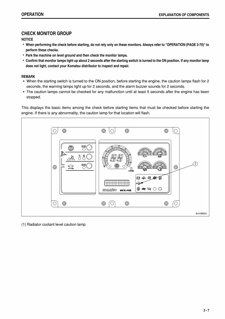
CHECK MONITOR GROUPNOTICE
When performing the check before starting, do not rely only on these monitors. Always refer to "OPERATION (PAGE 3-70)" toperform these checks.Park the machine on level ground and then check the monitor lamps.Confirm that monitor lamps light up about 2 seconds after the starting switch is turned to the ON position. If any monitor lampdoes not light, contact your Komatsu distributor to inspect and repair.
REMARKWhen the starting switch is turned to the ON position, before starting the engine, the caution lamps flash for 2seconds, the warning lamps light up for 2 seconds, and the alarm buzzer sounds for 2 seconds.The caution lamps cannot be checked for any malfunction until at least 5 seconds after the engine has beenstopped.
This displays the basic items among the check before starting items that must be checked before starting theengine. If there is any abnormality, the caution lamp for that location will flash.
(1) Radiator coolant level caution lamp
3 - 7

.
OPERATIONEXPLANATION OF COMPONENTS
RADIATOR COOLANT LEVEL CAUTION LAMPLamp (1) warns the operator that the coolant level in the main andsub radiators has gone down.If the lamp flashes, check the coolant level in the main and subradiators, and add coolant.
3 - 8

.
OPERATION EXPLANATION OF COMPONENTS
CAUTION MONITOR GROUP
CAUTIONIf these caution lamps flash, check and repair the appropriate location as soon as possible.
NOTICEPark the machine on level ground and check the monitor lamps.Confirm that monitor lamps light up about 2 seconds after the starting switch is turned to the ON position. If any monitor lampdoes not light, contact your Komatsu distributor to inspect and repair.
These are items which need to be observed when the engine is running. If any problem occurs, the item needingimmediate repair is displayed. If there is any problem, the problem location on the caution lamp will flash.
(1)(2)
Charge level caution lampMaintenance caution lamp
(3) Air cleaner clogging caution lamp
CHARGE LEVEL CAUTION LAMPLamp (1) indicates an abnormality in the charging system while theengine is running.If the monitor lamp flashes, check the V-belt tension. If anyabnormality is found, see "OTHER TROUBLE (PAGE 3-145)".
REMARKThis monitor lamp lights when the starting switch is turned to ONimmediately after the engine is started or immediately before theengine is stopped. It does not indicate a problem.
3 - 9

.
OPERATIONEXPLANATION OF COMPONENTS
MAINTENANCE CAUTION LAMPMonitor (2) flashes when the filter or oil change interval has beenreached. DISPLAY PANEL B (Multi-information) (PAGE 3-16) tothe maintenance mode and check or replace the applicable filter oroil.
3 - 10

.
OPERATION EXPLANATION OF COMPONENTS
EMERGENCY CAUTION ITEMS
CAUTIONIf the caution lamp for any of these items flashes, stop the engine immediately or run it at low idling, and take the following action.
NOTICEPark the machine on level ground and check the monitor lamps.Confirm that these caution lamps light for about 3 seconds after the starting switch is turned to ON. If any monitor lamp doesnot light, have your Komatsu distributor inspect and repair it.
These items need to be observed while the engine is running. If any abnormality occurs, items that need to berepaired immediately are displayed.If there is any abnormality, alarm buzzer sounds intermittently and the abnormal location on the caution lamp willflash.
C(1)C(2)
Engine oil pressure caution lampEngine cooling water temperature monitor
C(3)C(4)
Power train oil temperature monitorHydraulic oil temperature monitor
3 - 11
.
OPERATIONEXPLANATION OF COMPONENTS
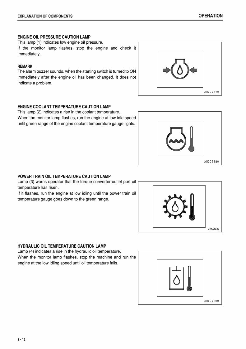
ENGINE OIL PRESSURE CAUTION LAMPThis lamp (1) indicates low engine oil pressure.If the monitor lamp flashes, stop the engine and check itimmediately.
REMARKThe alarm buzzer sounds, when the starting switch is turned to ONimmediately after the engine oil has been changed. It does notindicate a problem.
ENGINE COOLANT TEMPERATURE CAUTION LAMPThis lamp (2) indicates a rise in the coolant temperature.When the monitor lamp flashes, run the engine at low idle speeduntil green range of the engine coolant temperature gauge lights.
POWER TRAIN OIL TEMPERATURE CAUTION LAMPLamp (3) warns operator that the torque converter outlet port oiltemperature has risen.If it flashes, run the engine at low idling until the power train oiltemperature gauge goes down to the green range.
HYDRAULIC OIL TEMPERATURE CAUTION LAMPLamp (4) indicates a rise in the hydraulic oil temperature.When the monitor lamp flashes, stop the machine and run theengine at the low idling speed until oil temperature falls.
3 - 12

.
OPERATION EXPLANATION OF COMPONENTS
METER GROUPNOTICEWhile the engine is at rest, turn the starting switch to the ON position to see if the engine coolant temperature gauge, power trainoil temperature gauge, fuel level gauge, and monitor lamps all light up.If they do not, have your Komatsu distributor inspect and repair it.
(1)(2)(3)(4)(5)(6)
Engine coolant temperature gaugePower train oil temperature gaugeHydraulic oil temperature gaugeFuel level gaugeEngine pre-heating pilot lampTorque converter lock up pilot lamp
(7)
(8)
(9)
Dual/single tilt selector display lamp (dual tilt dozer specification)Display panel A (speed range display, engine speed)Display panel B (multi-information)
ENGINE COOLANT TEMPERATURE GAUGEGauge (1) indicates temperature of the engine coolant.If the temperature is normal during operation, green range (B) willlight.If red range (C) lights during operation, move the fuel control dial tolower engine speed to approx. 3/4 of the full speed, and run untilthe coolant temperature enters green range (B).During operation, if red range (C) lights, engine coolanttemperature monitor flashes and the alarm buzzer sounds, stopthe machine and run at low idle until coolant temperature entersgreen range (B).(A): White range(B): Green range(C): Red range
NOTICEIf the coolant temperature gauge often enters red range (C), check the radiator for clogging.
3 - 13

.
OPERATIONEXPLANATION OF COMPONENTS
POWER TRAIN OIL TEMPERATURE GAUGEGauge (2) indicates the torque converter outlet oil temperature.If the temperature is normal during operation, green range (B) willlight.If red range (C) lights up during operation, move the fuel control dialto lower engine speed to approx. 3/4 of the full speed, reduce theload and run until the oil temperature enters green range (B).If red range (C) lights up, the power train oil temperature cautionlamp flashes and the alarm buzzer sounds during operations, stopthe machine, and run the engine at low idling until the oiltemperature goes down to green range (B).(A): White range(B): Green range(C): Red range
NOTICEIf the power train oil temperature gauge often enters red range (C), shiftdown one speed range to reduce the load on the power train whenoperating.
HYDRAULIC OIL TEMPERATURE GAUGEGauge (3) indicates the hydraulic oil temperature.If the temperature is normal during operation, green range (B) willlight.If red range (C) lights up during operation, move the fuel control dialdown to approx. 3/4 of the full speed, reduce the load, and run untilthe oil temperature enters green range (B). If the oil temperaturesdoes not enter green range (B) even when the load is reduced,stop the work equipment control lever and run until the oiltemperature enters green range (B).(A): White range(B): Green range(C): Red range
FUEL LEVEL GAUGEGauge (4) fuel level in the fuel tank.During normal operation, the green range (B) should be lit.If red range (A) lights up during operation, add fuel immediately. Ifthis is not done, the engine speed will become irrgular or an errordisplay will be shown on the monitor.(A): Red range(B): Green range
REMARKThe display is not proportional to the amount of fuel remaining.If only the red range (A) lights up, there is less than 270 liters(71.34 US gal) of fuel remaining.
3 - 14
.
OPERATION EXPLANATION OF COMPONENTS
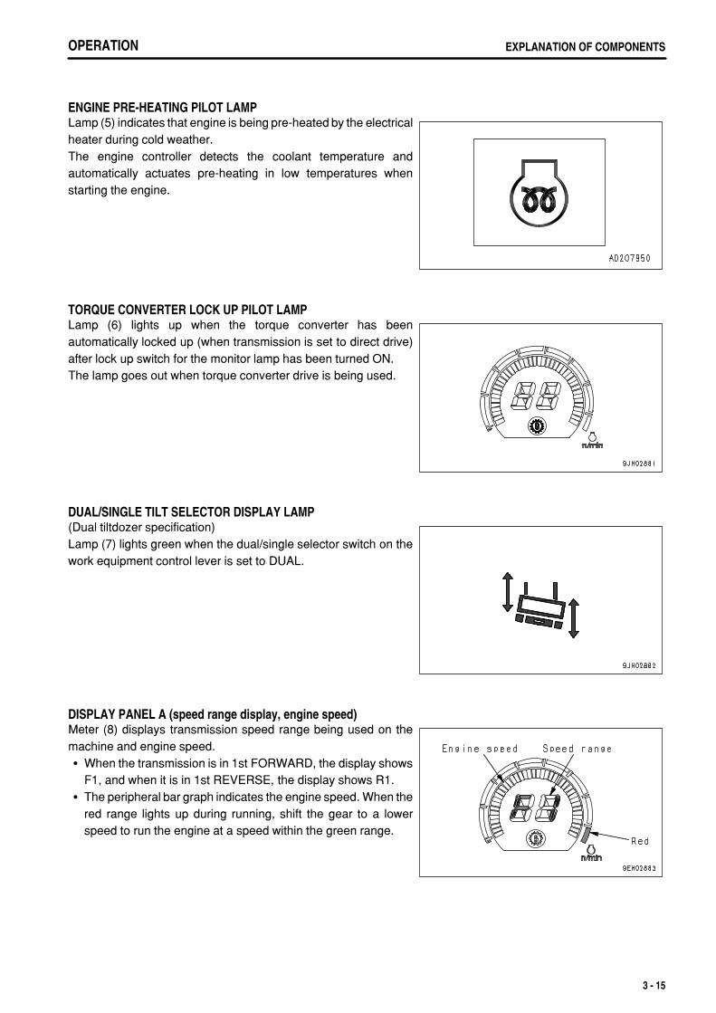
ENGINE PRE-HEATING PILOT LAMPLamp (5) indicates that engine is being pre-heated by the electricalheater during cold weather.The engine controller detects the coolant temperature andautomatically actuates pre-heating in low temperatures whenstarting the engine.
TORQUE CONVERTER LOCK UP PILOT LAMPLamp (6) lights up when the torque converter has beenautomatically locked up (when transmission is set to direct drive)after lock up switch for the monitor lamp has been turned ON.The lamp goes out when torque converter drive is being used.
DUAL/SINGLE TILT SELECTOR DISPLAY LAMP(Dual tiltdozer specification)Lamp (7) lights green when the dual/single selector switch on thework equipment control lever is set to DUAL.
DISPLAY PANEL A (speed range display, engine speed)Meter (8) displays transmission speed range being used on themachine and engine speed.
When the transmission is in 1st FORWARD, the display showsF1, and when it is in 1st REVERSE, the display shows R1.The peripheral bar graph indicates the engine speed. When thered range lights up during running, shift the gear to a lowerspeed to run the engine at a speed within the green range.
3 - 15

.
OPERATIONEXPLANATION OF COMPONENTS
DISPLAY PANEL B (Multi-information)This monitor (9) displays information related to the condition of the machine on the top and bottom lines of thedisplay portion. The content of the display can be switched by operating the service mode selector switch.
(1) Operating mode (normal operation screen)
Use this mode when operating the machine.
REMARKWhen starting switch is turned from the OFF position to the ONposition, the multi-information is set to the operating mode.
The shift mode selected by operation of the "GEARSHIFTINGUSING SHIFT MODE SELECTION (PAGE 3-99)" through the shiftmode selection is displayed on the left side of the monitor.The total operating hours of the machine is displayed at the bottomright of the monitor. (Use the service meter function display to setthe interval for periodic maintenance.)When the engine is running, the service meter advances, even ifthe machine is not moving.When the engine is running, the hourglass mark pilot display at theside of the meter lights up to show that the meter is advancing.The meter advances by 1 for every hour of operation, regardless ofthe engine speed.If there is a failure in the machine, the failure code is also displayedon the top line. If a failure code is displayed, carry out the remedygiven in "OTHER TROUBLE (PAGE 3-145)".
(2) Maintenance mode
The maintenance mode is displayed by continuing to turn thebuzzer cancel switch in the direction for 2.5 seconds.For details, see "METHOD OF USING DISPLAY PANEL B(Multi-information) (PAGE 3-24)".
3 - 16

.
OPERATION EXPLANATION OF COMPONENTS
MODE SELECTION SWITCH GROUPPress each mode switch to turn it ON or OFF and to select the mode.For details of setting the mode to use, see "EFFECTIVE USE OF MODE SELECTION SYSTEM (PAGE 3-114)".
It is impossible to use any combination of the lock up mode and any other mode.The economy mode, reverse slow mode, and shoe slip control mode can be used independently or incombination.
(1)(2)
Lock up mode switchEconomy mode switch
(3) Reverse slow mode selector switch
Selecting mode to match the type of work and quality of rock and soil makes to perform operations effectively.
: Possible to use : Compound use not possible
3 - 17
.
OPERATIONEXPLANATION OF COMPONENTS
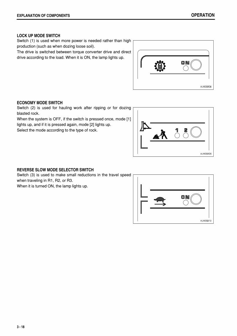
LOCK UP MODE SWITCHSwitch (1) is used when more power is needed rather than highproduction (such as when dozing loose soil).The drive is switched between torque converter drive and directdrive according to the load. When it is ON, the lamp lights up.
ECONOMY MODE SWITCHSwitch (2) is used for hauling work after ripping or for dozingblasted rock.When the system is OFF, if the switch is pressed once, mode [1]lights up, and if it is pressed again, mode [2] lights up.Select the mode according to the type of rock.
REVERSE SLOW MODE SELECTOR SWITCHSwitch (3) is used to make small reductions in the travel speedwhen traveling in R1, R2, or R3.When it is turned ON, the lamp lights up.
3 - 18

.
OPERATION EXPLANATION OF COMPONENTS
SWITCHES
F(1)F(2)F(3)F(4)
Starting switchBuzzer cancel switchFront lamp, working lamp switchRear lamp switch
F(5)F(6)F(7)
Auto shift down switchInformation switchAdditional heater switch (if equipped)
STARTING SWITCHSwitch (1) is used to start the engine.
OFFKey insertion-withdrawal position. None of electrical circuitsactivate.
ONCharging and electric device circuits activate. Keep key in the ONposition after starting.
STARTIn this key position, the starting motor will crank the engine.Immediately after starting the engine, release the key which willautomatically return to the ON position.
3 - 19

.
OPERATIONEXPLANATION OF COMPONENTS
BUZZER CANCEL SWITCHWhen switch (2) is operated to the left or right, the alarm buzzerstops.When the information monitor is in the maintenance mode, switch(2) can be operated to move the curser left or right.(a) position: Cancel(c) position: Select
FRONT LAMP/WORKING LAMP SWITCHSwitch (3) lights up when the front lamp, left and right workinglamps located on the front fender, and panel lamp light up.(a) OFF position: Goes out(b) ON position: Lights up
REAR LAMP SWITCHSwitch (4) lights up the rear lamp.(a) OFF position: goes off(b) ON position: lights up
AUTO SHIFT DOWN SWITCHIf switch (5) is turned to the right when the travel speed has gonedown because of load condition when traveling, the transmissionis automatically shifted to low speed.Position (a) (OFF): Auto shift down is canceledPosition (b) (ON): Transmission automatically shifts to low speed
For details, see "AUTO SHIFT DOWN OPERATION (PAGE3-100)".
3 - 20

.
OPERATION EXPLANATION OF COMPONENTS
INFORMATION SWITCHSwitch (6) is used to select the display mode for the informationinformation monitor and to move the curser in the maintenancemode.Position (a): Cursor moves to leftPosition (c): Cursor moves to right
ADDITIONAL HEATER SWITCH(If equipped)Switch (7) actuates the hot water heater.Position (a): Hot water heater OFFPosition (b): Hot water heater LOW (ON)Position (c): Hot water heater HIGH (ON)
3 - 21

.
OPERATIONEXPLANATION OF COMPONENTS
LAMPS
G(1) Warning lamp G(2) Filter, oil change interval lamp
WARNING LAMPNOTICEIf alarm buzzer sounds, stop work immediately and perform inspection andmaintenance of the appropriate point.
When the caution lamp for the CAUTION (B) and CAUTION (C)groups on the machine monitor system flashes, and anabnormallity has occured in the electronic control system, lamp (1)also flashes at the same time.If the lamp flashes, check the monitor panel to locate theabnormality.When the monitor inside the CAUTION (C) group flashes, thealarm buzzer also sounds continuously.See"FRONT PANEL (PAGE 3-5)".
3 - 22

.
OPERATION EXPLANATION OF COMPONENTS
FILTER/OIL CHANGE INTERVAL LAMPLamp (2) lights when it comes near the time for replacing the filteror oil.
3 - 23

.
OPERATIONEXPLANATION OF COMPONENTS
METHOD OF USING DISPLAY PANEL B (Multi-information)
EXPLANATION OF MODES AND CONTROLSDisplay panel B (1) has the function of displaying the followingfour types of mode. (The diagram on the right shows the normalscreen before the mode display.)Maintenance modeThis displays the time for replacing the filters or oil.PM clinic auxiliary modeThis displays the engine speed and the oil pressure in thehydraulic circuits.Fault display modeThis displays the fault code related to the electronic control.Adjustment modeThis adjusts the brightness and contrast of the display.There are variations (sub-items) in the four types of mode. For an explanation of the variations, see the followingitems.METHOD OF USING MAINTENANCE MODE (PAGE 3-26)METHOD OF USING PM CLINIC AUXILIARY MODE (PAGE 3-28)METHOD OF USING FAULT CODE DISPLAY MODE (PAGE 3-29)METHOD OF USING USER ADJUST MODE (PAGE 3-30)Each mode is operated by using information switch (2) andbuzzer cancel switch (3) on the dashboard in front of theoperator's seat.After operating the switch, release the switch, and the switch willreturn automatically to the center position as shown in thediagram on the right.The functions of each position of the switches are as follows.<: Moves mode to left>: Moves mode to right
: Selects mode: Cancels mode
The four types of mode can be selected in a cycle by operating information switch (2) to > and < to give thefollowing sequence: Maintenance mode ←→ PM clinic auxiliary mode ←→ Fault code display mode ←→ Adjustment mode ←→ Maintenance mode.From the normal mode before giving the mode display, if buzzer cancel switch (3) is operated to and held for2.5 seconds, the maintenance mode is displayed. After that, if information switch (2) is operated to >, the modechanges to the PM clinic auxiliary mode. If information switch (2) is operated to <, the mode changes to the useradjust mode.When any mode is being displayed, if the buzzer cancel switch is operated to , the screen returns the normalscreen shown before the mode display.
3 - 24

.
OPERATION EXPLANATION OF COMPONENTS
METHOD OF SELECTING MODES 1. When moving from the normal operation display to a user
mode, the maintenance mode is displayed. Use the controls tochange the mode as follows.> position: Go to PM clinic auxiliary mode< position: Go to user adjust mode
position: Go to normal operation screen position: Go to maintenance mode selection screen.
2. The diagram on the right shows the screen display for the PMclinic auxiliary mode. Use the controls to change the mode asfollows.> position: Go to fault code display mode< position: Go to maintenance mode
position: Go to normal operation screen position: Go to PM clinic auxiliary mode selection item
screen
3. The diagram on the right shows the screen display for the faultcode display mode. Use the controls to change the mode asfollows.> position: Go to adjustment mode< position: Go to PM clinic auxiliary mode
position: Go to normal operation screen position: Go to fault code selection item screen
4. The diagram on the right shows the screen display for the useradjust mode. Use the controls to change the mode as follows.> position: Go to maintenance mode< position: Go to fault code display mode
position: Go to normal operation screen position: Go to user adjust mode selection item screen
3 - 25
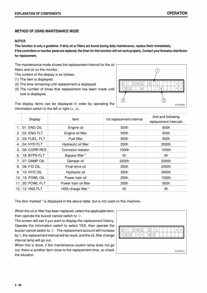
.
OPERATIONEXPLANATION OF COMPONENTS
METHOD OF USING MAINTENANCE MODE
NOTICEThis function is only a guideline. If dirty oil or filters are found during daily maintenance, replace them immediately.If the controllers or monitor panel are replaced, the timer for this function will not work properly. Contact your Komatsu distributorfor replacement.
The maintenance mode shows the replacement interval for the oilfilters and oil on the monitor.The content of the display is as follows.(1) The item is displayed.(2) The time remaining until replacement is displayed.(3) The number of times that replacement has been made until
now is displayed.
The display items can be displayed in order by operating theinformation switch to the left or right (<, >).
Display Item 1st replacement interval2nd and following
replacement intervals
1. 01: ENG OIL Engine oil 500h 500h
2. 02: ENG FLT Engine oil filter 500h 500h
3. 03: FUEL. FLT Fuel filter 500h 500h
4. 04: HYD FLT Hydraulic oil filter 250h 2000h
5. 06: CORR RES Corrosion resistor 1000h 1000h
6. 18: BYPS FLT Bypass filter * 0h 0h
7. 07: DAMP OIL Damper oil 2000h 2000h
8. 08: F/D OIL Final drive oil 250h 2000h
9. 10: HYD OIL Hydraulic oil 250h 2000h
10. 19: POWL OIL Power train oil 250h 1000h
11. 20: POWL FLT Power train oil filter 250h 500h
12. 12: HSS FLT HSS charge filter * 0h 0h
The item marked * is displayed in the above table, but is not used on this machine.
When the oil or filter has been replaced, select the applicable item,then operate the buzzer cancel switch to .The screen will ask if you want to display the replacement history.Operate the information switch to select YES, then operate thebuzzer cancel switch to . The replacement account will increaseby 1, the replacement interval will be reset, and the oil, filter changeinterval lamp will go out.When this is done, if the maintenance caution lamp does not goout, there is another item close to the replacement time, so checkthe situation.
3 - 26

.
OPERATION EXPLANATION OF COMPONENTSOPERATION EXPLANATION OF COMPONENTS
REMARKTo return to the function selection mode, operate the buzzer cancelswitch to .
3 - 27
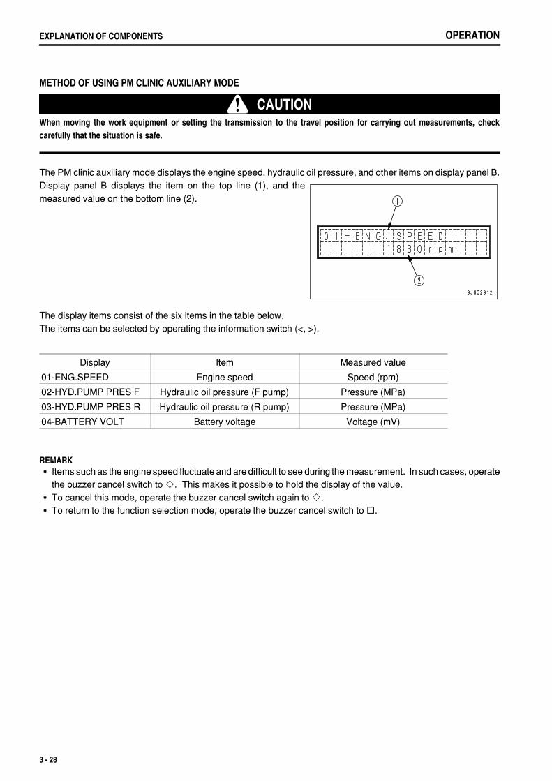
.
OPERATIONEXPLANATION OF COMPONENTS
METHOD OF USING PM CLINIC AUXILIARY MODE
CAUTIONWhen moving the work equipment or setting the transmission to the travel position for carrying out measurements, checkcarefully that the situation is safe.
The PM clinic auxiliary mode displays the engine speed, hydraulic oil pressure, and other items on display panel B.Display panel B displays the item on the top line (1), and themeasured value on the bottom line (2).
The display items consist of the six items in the table below.The items can be selected by operating the information switch (<, >).
Display Item Measured value
01-ENG.SPEED Engine speed Speed (rpm)
02-HYD.PUMP PRES F Hydraulic oil pressure (F pump) Pressure (MPa)
03-HYD.PUMP PRES R Hydraulic oil pressure (R pump) Pressure (MPa)
04-BATTERY VOLT Battery voltage Voltage (mV)
REMARKItems such as the engine speed fluctuate and are difficult to see during the measurement. In such cases, operatethe buzzer cancel switch to . This makes it possible to hold the display of the value.To cancel this mode, operate the buzzer cancel switch again to .To return to the function selection mode, operate the buzzer cancel switch to .
3 - 28
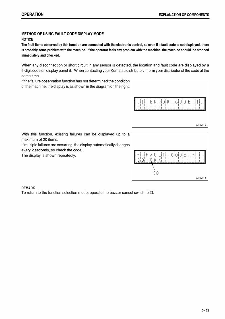
.
OPERATION EXPLANATION OF COMPONENTS
METHOD OF USING FAULT CODE DISPLAY MODENOTICEThe fault items observed by this function are connected with the electronic control, so even if a fault code is not displayed, thereis probably some problem with the machine. If the operator feels any problem with the machine, the machine should be stoppedimmediately and checked.
When any disconnection or short circuit in any sensor is detected, the location and fault code are displayed by a6-digit code on display panel B. When contacting your Komatsu distributor, inform your distributor of the code at thesame time.If the failure observation function has not determined the conditionof the machine, the display is as shown in the diagram on the right.
With this function, existing failures can be displayed up to amaximum of 20 items.If multiple failures are occurring, the display automatically changesevery 2 seconds, so check the code.The display is shown repeatedly.
REMARKTo return to the function selection mode, operate the buzzer cancel switch to .
3 - 29

.
OPERATIONEXPLANATION OF COMPONENTS
METHOD OF USING USER ADJUST MODEWith the user adjust mode, the brightness of the panel screen backlighting and the contrast of the liquid crystal panelcan be changed, or the cooling fan can be set to maximum speed to clean the radiator when it is clogged.These are displayed on display panel B.
1. Adjusting backlighting of liquid crystal displayThe diagram on the right is the mode for adjusting thebrightness of the backlighting of the liquid crystal panel. Onthis screen, operate the buzzer cancel switch to to switch tothe screen to adjust the brightness.
The brightness can be adjusted by operating the informationswitch.The higher the number, the brighter the screen becomes; the lowerthe number, the darker the screen becomes.> position: Number increases< position: Number decreases
When the buzzer cancel switch is operated to , the brightness ofthe liquid crystal display backlighting is set.
2. Adjusting backlighting of message displayThe diagram on the right is the mode for adjusting thebrightness of the backlighting of the message display. On thescreen, operate the buzzer cancel switch to to switch to thescreen for adjusting the brightness.
3 - 30

.
OPERATION EXPLANATION OF COMPONENTSOPERATION EXPLANATION OF COMPONENTS
The brightness can be adjusted by operating the informationswitch.The higher the number, the brighter the screen becomes; the lowerthe number, the darker the screen becomes.> position: Number increases< position: Number decreases
When the buzzer cancel switch is operated to , the brightness ofthe message display backlighting is set.
3. Adjusting contrast of liquid crystal message displayThe diagram on the right is the mode for adjusting the contrastof the liquid crystal message display.On this screen, operate the buzzer cancel switch to toswitch to the screen to adjust the contrast.
The contrast can be adjusted by operating the information switch.The higher the number, the darker the screen becomes; the lowerthe number, the lighter the screen becomes.> position: Number increases< position: Number decreases
When the buzzer cancel switch is operated to , the contrast ofthe liquid crystal display is set.
3 - 31

.
OPERATIONEXPLANATION OF COMPONENTS
REMARKTo return to the function selection mode, operate the buzzer cancel switch to .The brightness of the backlighting of the monitor panel differs according to whether the front lamp is lit or not.Entering this mode when the front lamps are lit makes it possible to adjust the brightness when the front lampsare lit. In the same way, entering this mode when the front lamps are not lit makes it possible to adjust thebrightness when the front lamps are not lit.
3 - 32

.
OPERATION EXPLANATION OF COMPONENTS
SWITCHES
(1)(2)(3)(4)
Horn switchRoom lamp switchWiper switchCigarette lighter
(5)(6)(7)
Accessory socketConnector for VHMS downloadConnector for VHMS download
HORN SWITCHThe horn sounds when button (1) at rear of the blade control leveron the right side of operator's seat is pressed.
3 - 33

.
OPERATIONEXPLANATION OF COMPONENTS
ROOM LAMP SWITCHSwitch (2) lights the room lamp.ON position: Lamp lights upOFF position: Lamp is out
WIPER SWITCHSwitch (3) activates the wipers.The wiper switches are as follows:(A) L.H. door(B) Front window(C) R.H. door(D) Rear windowThis is also used as the window washer switch.The switch is operated as follows.
Window washer onlyKeep the switch pressed to the OFF position to spray out water.
Wiper onlyIf this is switched on, the wiper will start.
3 - 34

.
OPERATION EXPLANATION OF COMPONENTSOPERATION EXPLANATION OF COMPONENTS
Wiper and window washerIf this is kept pressed to the ON position while the wiper isworking, water will be sprayed out.
REMARKWhen installing the cab, check the colors of the washer tank andwindow washer hoses, and be sure to connect correctly.
3 - 35
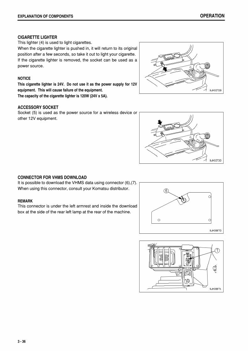
.
OPERATIONEXPLANATION OF COMPONENTS
CIGARETTE LIGHTERThis lighter (4) is used to light cigarettes.When the cigarette lighter is pushed in, it will return to its originalposition after a few seconds, so take it out to light your cigarette.If the cigarette lighter is removed, the socket can be used as apower source.
NOTICEThis cigarette lighter is 24V. Do not use it as the power supply for 12Vequipment. This will cause failure of the equipment.The capacity of the cigarette lighter is 120W (24V x 5A).
ACCESSORY SOCKETSocket (5) is used as the power source for a wireless device orother 12V equipment.
CONNECTOR FOR VHMS DOWNLOADIt is possible to download the VHMS data using connector (6),(7).When using this connector, consult your Komatsu distributor.
REMARKThis connector is under the left armrest and inside the downloadbox at the side of the rear left lamp at the rear of the machine.
3 - 36
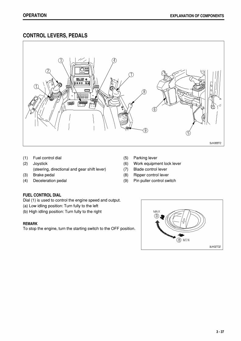
.
OPERATION EXPLANATION OF COMPONENTS
CONTROL LEVERS, PEDALS
(1)(2)
(3)(4)
Fuel control dialJoystick (steering, directional and gear shift lever)Brake pedalDeceleration pedal
(5)(6)(7)(8)(9)
Parking leverWork equipment lock leverBlade control leverRipper control leverPin puller control switch
FUEL CONTROL DIALDial (1) is used to control the engine speed and output.(a) Low idling position: Turn fully to the left(b) High idling position: Turn fully to the right
REMARKTo stop the engine, turn the starting switch to the OFF position.
3 - 37

.
OPERATIONEXPLANATION OF COMPONENTS
JOYSTICK (STEERING, DIRECTIONAL AND GEAR SHIFT LEVER)(PCSS lever)Lever (2) is used to switch direction of travel and to steer themachine.
REMARKPCCS: Palm command control system
Forward-reverse shiftingPosition (a): FORWARDPosition (b): REVERSEPosition N: NeutralMove to the front to drive forward; move to the rear to drive inreverse.
SteeringPosition (L): Left turnPosition (R): Right turnWith the lever moved to the front or rear, operate the lever partially to the left or right to turn the machine. Themachine will turn gradually in the same direction as the lever is operated.If the lever is moved fully to the left or right, the machine will turn in a small radius.
REMARKIf the lever is released when steering the machine, the lever will return to the (a) position or the (b) position andthe machine will be returned to straight movement.
Gear shiftingWhen the steering, directional, and gearshift lever is at theFORWARD or REVERSE position and switch (c) or switch (d) ispushed, the transmission speed will change.UP switch (c): Each time the switch is pressed, the transmission
will shift up one speed.DOWN switch (d): Each time the switch is pressed, the
transmission will shift down one speed.For details of the maximum speed in each speed range, see"SPECIFICATIONS (PAGE 5-2)".
REMARKWhen the transmission is shifted, the speed range being used is displayed on the display panel on the monitorpanel.Example:Neutral: N is displayed on the display panel.FORWARD 2nd: F2 is displayed on the display panel.REVERSE 3rd: R3 is displayed on the display panel.When the parking lever is locked, P is displayed.For details of the gearshift operation using the shift mode, see "SHIFTING GEAR (PAGE 3-98)". Shift modeselection means the operation to set the selected speed range beforehand in the N position.
3 - 38

.
OPERATION EXPLANATION OF COMPONENTS
BRAKE PEDAL
WARNINGDo not place your foot on this pedal unnecessarily.
Depress the pedal (3) to apply the right and left brakes.
DECELERATOR PEDAL
WARNINGDo not rest your foot on the pedal if you are not using it.When passing over the top of a slope or when dumping soil from a cliff,the load on the machine will suddenly be reduced and the travel speedwill increase. This situation is dangerous, so use the decelerator pedalto reduce the travel speed of the machine
Pedal (4) is used when reducing engine speed or stopping themachine.When switching between forward and reverse, or when stoppingthe machine, use this pedal to reduce speed.
REMARKWhen operating the decelerator pedal, there may be a particularnoise, but there is no problem with quality or durability.
PARKING LEVER
WARNINGWhen parking the machine, always set the parking brake lever to the LOCKposition.
This lever (5) is used to apply the parking brake.
REMARKBefore moving the parking brake lever to the LOCK position,return the steering, directional, and gearshift lever to the Nposition.When starting the engine, if the parking brake lever is not in theLOCK position, the limit switch is actuated and it is impossibleto start the engine.
3 - 39

.
OPERATIONEXPLANATION OF COMPONENTS
SAFETY LOCK LEVER
WARNINGWhen standing up from the operator's seat, always move the workequipment lock lever securely to the LOCK position.If the blade control and ripper control levers are not locked and aretouched by accident, it may lead to serious injury or damage.If the work equipment lock lever is not completely in the LOCK position,the lock may not be applied.Check that it is in the position shown in the diagram.When parking the machine or when performing maintenance, alwayslower the blade or ripper to the ground, then set the work equipmentlock lever to the LOCK position.
Lever (6) is a device to lock the blade control and ripper control levers.When it is set to the LOCK position, the TILT, RAISE, LOWER, and FLOAT operations are locked.
REMARKWhen starting the engine, to ensure safety, always set the work equipment lock lever to the LOCK position.
3 - 40
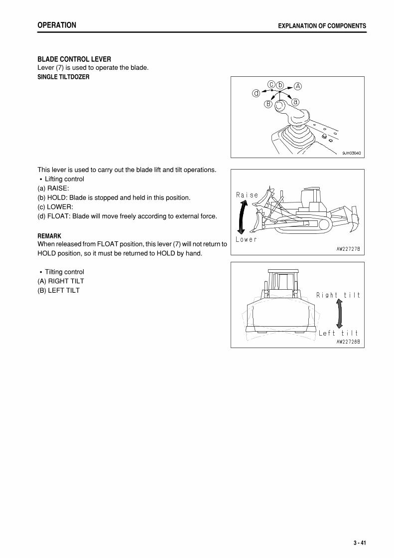
.
OPERATION EXPLANATION OF COMPONENTS
BLADE CONTROL LEVERLever (7) is used to operate the blade.SINGLE TILTDOZER
This lever is used to carry out the blade lift and tilt operations.Lifting control
(a) RAISE:(b) HOLD: Blade is stopped and held in this position.(c) LOWER:(d) FLOAT: Blade will move freely according to external force.
REMARKWhen released from FLOAT position, this lever (7) will not return toHOLD position, so it must be returned to HOLD by hand.
Tilting control(A) RIGHT TILT(B) LEFT TILT
3 - 41

.
OPERATIONEXPLANATION OF COMPONENTS OPERATIONEXPLANATION OF COMPONENTS
DUAL TILTDOZEROperate the tilt switch to the (D) position.
This lever is used to carry out the blade lift and tilt operations.Lifting control
(a) RAISE:(b) HOLD: Blade is stopped and held in this position.(c) LOWER:(d) FLOAT: Blade will move freely according to external force.
REMARKWhen released from FLOAT position, this lever (7) will not return toHOLD position, so it must be returned to HOLD by hand.
3 - 42

.
OPERATION EXPLANATION OF COMPONENTSOPERATION EXPLANATION OF COMPONENTS
TILT OPERATION(A) RIGHT TILT(B) LEFT TILT
REMARKWith the dual tilt operation, a larger amount of tilt can beobtained than with the single tilt operation.With the dual tilt operation, the blade can be operated to RAISE,HOLD, or LOWER.
Single tilt operationOperate the tilt switch to the (C) position.(A) RIGHT TILT(B) LEFT TILT
Pitch controlRear pitch (cutting angle reduced)Carry out operation (B) with the pitch button pressed.
Forward pitch (cutting angle increased)Carry out operation (A) with the pitch button pressed.
REMARKWith the pitch operation, the blade can be operated to any of RAISE, HOLD, or LOWER.For details of the effective use of the dual tiltdozer, see "EFFECTIVE METHOD OF OPERATION FOR DUALTILTDOZER (PAGE 6-6)".To operate the pitch, keep the pitch button pressed and operate the blade control lever to the left or right to startthe operation.The pitch is the priority circuit, so if the pitch button is pressed during tilt operation, the pitch will be actuated.
3 - 43

.
OPERATIONEXPLANATION OF COMPONENTS
RIPPER CONTROL LEVER(For variable ripper)Lever (8) is used to operate the ripper.(a) RAISE(b) HOLD: Ripper is stopped and held in the same position.(c) LOWER(A) Digging angle reduced: Cutting angle (α) becomes smaller.(B) Digging angle increased: Cutting angle (α) becomes larger.
3 - 44
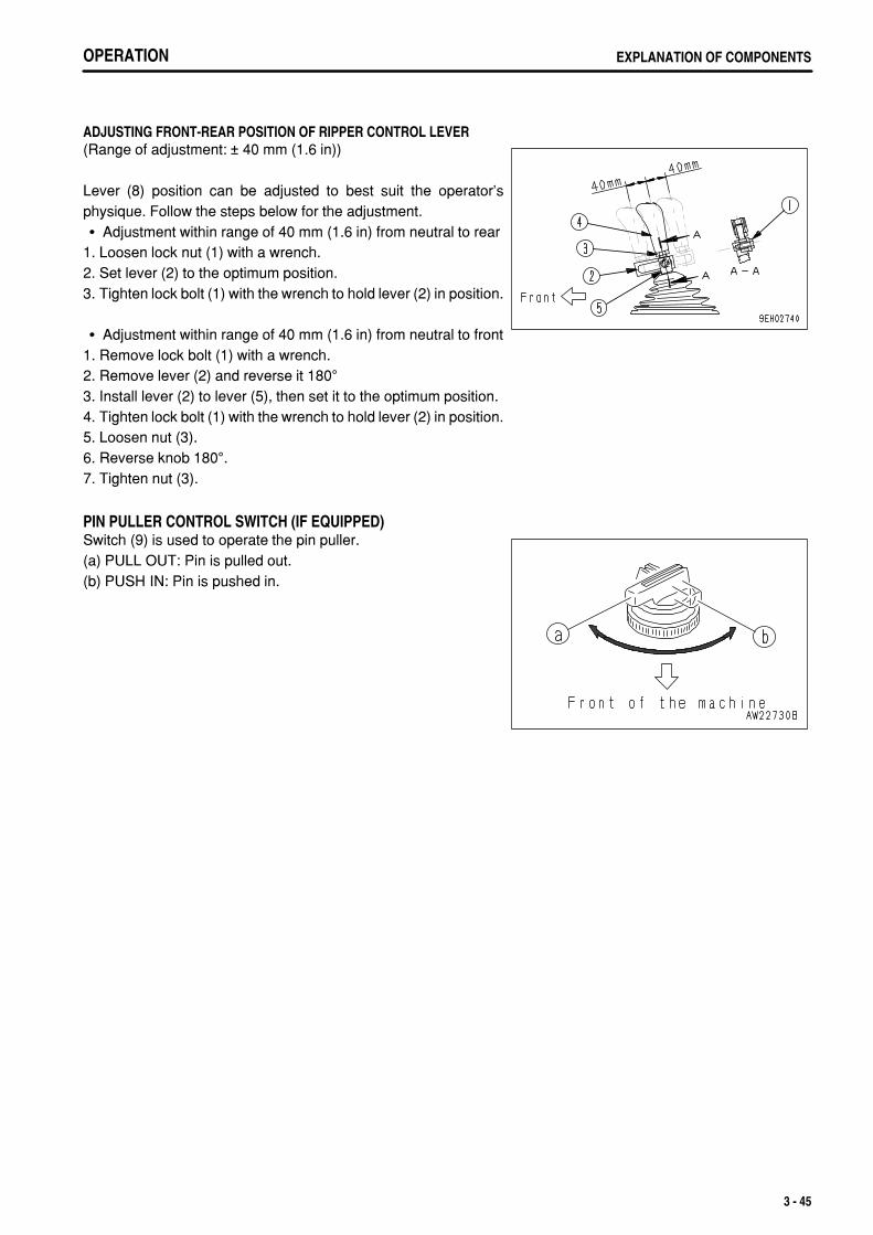
.
OPERATION EXPLANATION OF COMPONENTS
ADJUSTING FRONT-REAR POSITION OF RIPPER CONTROL LEVER(Range of adjustment: ± 40 mm (1.6 in))
Lever (8) position can be adjusted to best suit the operator'sphysique. Follow the steps below for the adjustment.
Adjustment within range of 40 mm (1.6 in) from neutral to rear1. Loosen lock nut (1) with a wrench.2. Set lever (2) to the optimum position.3. Tighten lock bolt (1) with the wrench to hold lever (2) in position.
Adjustment within range of 40 mm (1.6 in) from neutral to front1. Remove lock bolt (1) with a wrench.2. Remove lever (2) and reverse it 180°3. Install lever (2) to lever (5), then set it to the optimum position.4. Tighten lock bolt (1) with the wrench to hold lever (2) in position.5. Loosen nut (3).6. Reverse knob 180°.7. Tighten nut (3).
PIN PULLER CONTROL SWITCH (IF EQUIPPED)Switch (9) is used to operate the pin puller.(a) PULL OUT: Pin is pulled out.(b) PUSH IN: Pin is pushed in.
3 - 45

.
OPERATIONEXPLANATION OF COMPONENTS
CONTROLLERNOTICEIf any abnormality occurs, the failure mode is displayed on the service meter display. For details, see "OTHER TROUBLE (PAGE3-145)".
(1) Steering controller(2) Transmission controller
(3) Engine controller
STEERING CONTROLLER(In the rear side of the operator's seat)This controller (1) carries out electronic control of the steering andshoe slip control. If there is any abnormality, the failure mode isdisplayed in the service meter portion.
When the condition is normal,The service meter is displayed on display panel B (service meterportion).
3 - 46

.
OPERATION EXPLANATION OF COMPONENTS
TRANSMISSION CONTROLLER(In the rear side of the operator's seat)This controller carries out electronic control of the work equipmentand lock-up torque converter. If any abnormality occurs, the failuremode is displayed on the service meter display.
When the condition is normal,The hourglass mark and service meter are displayed on displaypanel B (service meter portion).
ENGINE CONTROLLER(Left side of engine)This controller (3) carries out electronic control of the engine speedand output. If there is any abnormality, the failure mode isdisplayed in the service meter portion.
When the condition is normal,The hourglass mark and service meter are displayed on displaypanel B (service meter portion).
DUST INDICATORThis is on the air cleaner bracket inside the engine room.This device indicates that the air cleaner element is clogged.For details on how to clean the element, see "CHECK, CLEANAND REPLACE AIR CLEANER ELEMENT (PAGE 4-25)".
POWER SOURCEThe cigarette lighter socket (1) can be used as a power source for24V equipment and the accessory socket (2) can be used for 12Vequipment.
NOTICEThe cigarette lighter is 24V. Do not use it as the power source for 12Vequipment.The capacity of the cigarette lighter is 120W (24V x 5A).The capacity of the accessory socket is 60W (12V x 5A).
3 - 47

.
OPERATIONEXPLANATION OF COMPONENTS
FUSE BOXNOTICEBefore replacing a fuse, be sure to turn off the starting switch.
Fuses protect the electrical equipment and wiring from burning out.If a fuse becomes corroded, or white powder can be seen, or a fuse is loose in the holder, replace the fuse.Replace a fuse with another of the same capacity.
ChassisOpen the fuse inspection cover at the bottom front left of theoperator's compartment. Fuse box I is installed inside.
(1) Fuse box fs1(2) Fuse box fs2(3) Fuse box fs4(4) Circuit breaker
Cab (machines equipped with cab)Fuse box II is installed at the bottom of the overhead panel.
3 - 48

.
OPERATION EXPLANATION OF COMPONENTS
CIRCUIT BREAKERIf the starting switch does not work even when the startingswitch is turned to the ON position, open the circuit breaker boxand check.If excessive current flows through the circuit breaker, it cuts offthe electric circuit to prevent damage to the electricalcomponents and wiring.To restore the electric circuit after it has been cut off, push inreset button (1). (This springs out when the circuit is cut off.)If the electric circuit is normal, reset button (1) will stay pushedin. If it comes out immediately when it is pushed in, the electriccircuit must be checked.
REMARKThe circuit breaker is a device installed in electric circuits where alarge current flows. It is installed to protect the electric circuit. Itprotects the electric components and wiring from damage causedby an abnormal current in the same way as a normal fuse. Afterrepairing and restoring the location of the abnormality, there is noneed to replace the breaker. It can be used again.
3 - 49

.
OPERATIONEXPLANATION OF COMPONENTS
FUSE CAPACITY AND NAME OF CIRCUIT
FUSE BOX I
(1) Fuse box fs1
No.Fuse
capacityCircuit
1 20A
2 20A CAB continuous power
3 10A Engine controller
4 10A Engine controller
5 20A VHMS continuous power
(2) Fuse box fs2
No.Fuse
capacityCircuit
1 20A Auxiliary power 1
2 20A
3 20A Add heater power
4 20A work lamp
5 20A Rear lamp
(3) Fuse box fs4
No.Fuse
capacityCircuit
1 20A Back up alarm pin puller
2 20A Auxiliary power 2
3 20A VHMS controller
4 20A Ribbon heater, Horn
5 20A Auxiliary acc signal
(4) Circuit breaker
No.Fuse
capacityCircuit
1 20A Steering controller
2 20A Monitor panel
3 20A Transmission controller
4 20A Air con main power
5 20A Head lamp
6 20A Starter switch
3 - 50

.
OPERATION EXPLANATION OF COMPONENTS
FUSE BOX II
NO.Fuse
capacityCircuit
(1) 10A Radio memory
(2) 20A Radio, lamp, cigarette lighter
(3) 10A Rear wiper
(4) 10A Right door wiper
(5) 10A Front wiper
(6) 10A Left door wiper
FUSIBLE LINKIf the starting motor does not work even when the starting switch isturned to the ON position, there may be a disconnection in fusiblelinks (1) and (2) on top of the wiring, so remove the cover at the rearof the battery box cover on the left side of the machine and checkor replace.
Capacity of (1): 96 ACapacity of (2): 32 A
REMARKA fusible link refers to the large-sized fuse wiring installed in the high current flow portion of the circuit to protectelectrical components and wiring from burning, in the same way as an ordinary fuse.
3 - 51

.
OPERATIONEXPLANATION OF COMPONENTS
DOOR OPEN LOCKUse this when your want to keep the door held open. 1. Push the door against door catch (1). The door will be held by
the door catch.
2. To release the door, move lever (2) inside the cab forward. Thiswill release the catch.
NOTICEWhen keeping the door open, fix it securely to the catch.Always close the door when traveling or carrying out operations.Leaving the door open will cause the door to break.Keep the door locked open securely. The door may swing closedbecause of the vibration.
SASH GLASS INTERMEDIATE LOCKWhen working with the cab sash glass open, use this lock toprevent the glass from chattering.
When the lever is in the FREE position, the glass can be openedor closed.When the lever is moved to the LOCK (up or down) position, theglass is fixed in position.If the glass is not held securely, set the lever in the FREEposition and rotate clockwise to strengthen the holding power.To reduce the holding power, turn counterclockwise.
NOTICEAlways close the window when traveling or carrying out operations.Leaving the window open will cause the window to break.
3 - 52

.
OPERATION EXPLANATION OF COMPONENTS
DOOR POCKETThis is inside the left and right doors. Use it for keeping things.Do not put the heavy tools or other heavy objects in it.If the pocket is dirty, loosen three bolts (1), then remove the pocketand rinse it.
ASHTRAYThis is on the left side of the operator's seat.Always make sure that you extinguish the cigarette before closingthe lid.
TOOL BOXThis is inside the front of the right fender.It is used for storing tools.
3 - 53

.
OPERATIONEXPLANATION OF COMPONENTS
CAR STEREO, HANDLING
EXPLANATION OF COMPONENTS
(1)(2)(3)(4)(5)(6)(7)
(A)(B)(C)(D)
Power switch/volumeAuto-store/preset scan buttonBass control knobTreble control knobLoudness buttonTime/radio display selector buttonTape eject button
Band displayMetal tape displayFM stereo reception displayLoudness display
(8)(9)(10)(11)(12)(13)(14)
(E)(F)(G)
Cassette doorFast forward, rewind buttonsPreset buttonsMetal tape buttonManual tuning buttonsSeek tuning buttonsBand selector button
Tape direction displayPreset channel displayTime/frequency display
3 - 54

.
OPERATION EXPLANATION OF COMPONENTS
POWER SWITCH/VOLUMETurn this knob (1) to the right until it clicks to turn the power on.Turn it further to increase the volume.
AUTO-STORE/PRESET SCAN BUTTONUse this button (2) to actuate the preset scan and auto-storefunctions.
Auto-storeEach time this button is pressed for more than 2 seconds whilein radio reception, this auto-store function automatically starts tosearch for the desired station within a receivable band, andmemorize the frequency in the preset memory. During thisscanning process, the frequency shown in the right side ofdisplay continues to change. This indicates that each frequencyis memorized in the auto-store.
REMARKThe auto-store function cannot be used when the channel displayis flashing.When the display is flashing, the preset scan function is beingused.
BASS CONTROL KNOBTurn this button (3) to the left to reduce the low tones; turn it to theright to emphasize the low tones.Direction (a): Low tone reducedDirection (b): Low tone emphasized
3 - 55

.
OPERATIONEXPLANATION OF COMPONENTS
TREBLE CONTROL KNOBTurn this button (4) to the left to reduce the low tones; turn it to theright to emphasize the high tones.Direction (a): High tone reducedDirection (b): High tone emphasized
LOUDNESS BUTTONThis button (5) is used when playing at low volume. It makes itpossible to hear more easily by emphasizing the low tone when thelow tones are weak.Push button: Actuated (ON)Push button again: Canceled (OFF)
TIME/RADIO DISPLAY SELECTOR BUTTONThis button (6) is used to switch between the "Radio/tape display"and the "Time display".
Correcting timePress the button to set to the time display.(A) Correcting hour :
Keep the DISP button pressed and press the bottom tuningbutton (H) to correct the hour.
(B) Correcting minute :Keep the DISP button pressed and press the top tuningbutton (M) to correct the minute.
3 - 56

.
OPERATION EXPLANATION OF COMPONENTS
TAPE EJECT BUTTONThis button (7) is used to stop the tape and to eject the cassette.When this button is pressed, the tape is ejected and the radioplays.
CASSETTE DOORSet the cassette with the exposed portion of the tape on the rightside and insert it through the cassette door (8).
FAST FORWARD, REWIND BUTTONSThese buttons (9) are used to fast-forward or rewind the tape.
Fast forward/rewindIf you press the button pointing in the same direction as thearrow indicating the direction of play, the tape will be fastforwarded; if you press the button pointing in the oppositedirection, the tape will be rewound.To stop the tape, lightly press the button that is not locked. Thefast forward or rewind operation will be canceled.
PRESET BUTTONSThese buttons (10) are used to call up the broadcast stationfrequencies preset in memory for each of buttons No. 1 to No. 6.It is possible to preset 18 stations (FM: 12; AM: 6) with thesebuttons.
3 - 57

.
OPERATIONEXPLANATION OF COMPONENTS
METAL TAPE BUTTON(used also for preset button No. 5)This button (11) is used when playing a metal or chrome tape. Thisbutton is also used for preset button No. 5. When it is pressed,"MTL" appears on the display.
MANUAL TUNING BUTTONSThese buttons (12) are used for manual tuning.When "TUN ∧" button is pressed, the frequency goes up 9 kHz forAM or 0.1 MHz for FM; when "TUN ∨" button is pressed, thefrequency goes down 9 kHz for AM or 0.1 MHz for FM.If the button is pressed down and held, the frequency will changecontinuously.
SEEK TUNING BUTTONSThese buttons (13) are used to seek tuning.When the "SEEK UP" button is pressed, the search automaticallygoes up; when the "SEEK DN" button is pressed, the searchautomatically goes down.When the next station that can be received is found, itautomatically stops.
BAND SELECTOR BUTTONWhen this button (14) is pressed, the band is switched betweenFM1, FM2, and MW (AM). The band is shown on the display.
3 - 58

.
OPERATION EXPLANATION OF COMPONENTS
METHOD OF OPERATION
METHOD OF SETTING PRESET BUTTONSTo listen to a preset station, use band selector button (1) to selectAM, FM1, or FM2, then press the preset switch number to listen tothe desired station.It is possible to preset six AM stations and 12 FM stations (FM1: 6,FM2: 6). 1. If you are playing a cassette, press the tape eject button to stop
the tape. 2. Select the station to be preset.
Use band selector button (1) to select MW (AM), FM1, or FM2,then use the manual tuning button to select the frequency ofthe broadcasting station.
3. Press manual memory button (2) or seek tuning button (3). 4. Press preset button (4) of the number to be preset for 2
seconds while the frequency display is being shown on thedisplay. (The preset channel and frequency are displayed andthe presetting is completed).
5. Repeat Steps 2 to 4 to preset other stations.
REMARKUse Steps 2 to 4 also when changing the setting of a presetswitch to another station.When the power is disconnected, such as when the battery isreplaced, all the settings are deleted, so preset the stationsagain.
MANUAL MEMORY BUTTONSelect the station to be preset with manual tuning button (1) orseek tuning button (2), then keep button No.1 to button No.6 ofbutton (3) pressed for 2 seconds while the frequency is beingdisplayed to preset the station.
3 - 59

.
OPERATIONEXPLANATION OF COMPONENTS
LISTENING TO RADIO 1. Turn the starting switch ON, then turn power switch (1) ON. 2. Set band selector button (2) to AM or FM. 3. Select the station with the preset buttons or manual tuning
button (3). 4. Adjust the volume, balance, and tone as desired. 5. When turning the radio OFF, turn power switch (1) to the left
until it clicks.
REMARKTo switch to the radio when listening to a cassette, press the cassette eject button to stop the tape.If you insert a cassette when listening to the radio, the tape will start to play.
LISTENING TO CASSETTE TAPE 1. Turn the starting switch ON, then turn power switch (1) ON. 2. Set the cassette with the exposed portion of the tape on the
right side and push it past the cassette door. The tape willautomatically start playing.If the arrow indicating the direction of play is pointing to theright, the top side is being played; if the arrow is pointing to theleft, the bottom side is being played.When the tape reaches the end, it is automatically reversedand the other side starts to play.
3. When finished with the tape, press the cassette eject button toeject the tape and automatically switch to the radio.
3 - 60
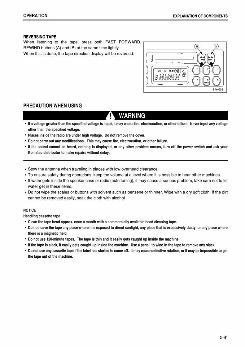
.
OPERATION EXPLANATION OF COMPONENTS
REVERSING TAPEWhen listening to the tape, press both FAST FORWARD,REWIND buttons (A) and (B) at the same time lightly.When this is done, the tape direction display will be reversed.
PRECAUTION WHEN USING
WARNINGIf a voltage greater than the specified voltage is input, it may cause fire, electrocution, or other failure. Never input any voltageother than the specified voltage.Places inside the radio are under high voltage. Do not remove the cover.Do not carry out any modifications. This may cause fire, electrocution, or other failure.If the sound cannot be heard, nothing is displayed, or any other problem occurs, turn off the power switch and ask yourKomatsu distributor to make repairs without delay.
Stow the antenna when traveling in places with low overhead clearance.To ensure safety during operations, keep the volume at a level where it is possible to hear other machines.If water gets inside the speaker case or radio (auto tuning), it may cause a serious problem, take care not to letwater get in these items.Do not wipe the scales or buttons with solvent such as benzene or thinner. Wipe with a dry soft cloth. If the dirtcannot be removed easily, soak the cloth with alcohol.
NOTICEHandling cassette tape
Clean the tape head approx. once a month with a commercially available head cleaning tape.Do not leave the tape any place where it is exposed to direct sunlight, any place that is excessively dusty, or any place wherethere is a magnetic field.Do not use 120-minute tapes. The tape is thin and it easily gets caught up inside the machine.If the tape is slack, it easily gets caught up inside the machine. Use a pencil to wind in the tape to remove any slack.Do not use any cassette tape if the label has started to come off. It may cause defective rotation, or it may be impossible to getthe tape out of the machine.
3 - 61
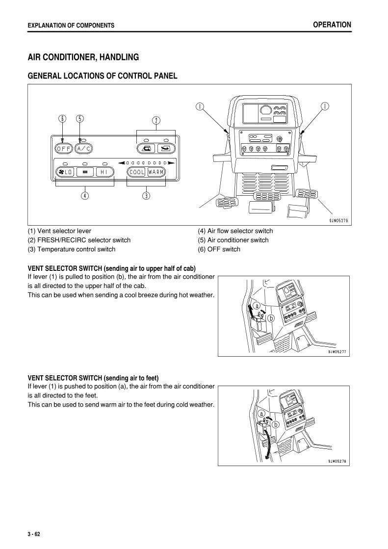
.
OPERATIONEXPLANATION OF COMPONENTS
AIR CONDITIONER, HANDLING
GENERAL LOCATIONS OF CONTROL PANEL
(1) Vent selector lever(2) FRESH/RECIRC selector switch(3) Temperature control switch
(4) Air flow selector switch(5) Air conditioner switch(6) OFF switch
VENT SELECTOR SWITCH (sending air to upper half of cab)If lever (1) is pulled to position (b), the air from the air conditioneris all directed to the upper half of the cab.This can be used when sending a cool breeze during hot weather.
VENT SELECTOR SWITCH (sending air to feet)If lever (1) is pushed to position (a), the air from the air conditioneris all directed to the feet.This can be used to send warm air to the feet during cold weather.
3 - 62

.
OPERATION EXPLANATION OF COMPONENTS
FRESH/RECIRC SELECTOR SWITCH (RECIRCULATE)When switch (2) is pressed, the air inside the cab is recirculatedand no fresh air is taken in from outside. This position is used whenheating or cooling the cab quickly or when the outside air is dirty.
FRESH/RECIRC SELECTOR SWITCH (FRESH)When switch (2) is pressed, fresh air is taken into the cab duringheating or cooling.This position is used to bring in clean fresh air into the cab or toremove the mist from the cab windows.
TEMPERATURE INDICATORThe further the indicator is in the blue range, the lower thetemperature is; the further the indicator is in the red range, thehigher the temperature is.The indicator range is divided into 7 levels, but within each rangethe temperature changes sleeplessly.
TEMPERATURE CONTROL SWITCH (COOL)Use switch (3) to reduce the temperature.Press this switch to reduce the temperature of the air sent from theair conditioner.The lower the temperature becomes, the further the indicatormoves into the blue range.
3 - 63

.
OPERATIONEXPLANATION OF COMPONENTS
TEMPERATURE CONTROL SWITCH (WARM)Use switch (3) to increase the temperature.Press this switch to increase the temperature of the air sent fromthe air conditioner.The higher the temperature becomes, the further the indicatormoves into the red range.
AIR FLOW SELECTOR SWITCH (LO)Switch (4) is used to set the flow of air from the air conditioner toLOW.When this switch is pressed, the air flow is set to the minimumamount of the three available levels.
AIR FLOW SELECTOR SWITCH (MID)Switch (4) is used to set the flow of air from the air conditioner toMID. When this switch is pressed, the air flow is set to the mediumamount of the three available levels.
AIR FLOW SELECTOR SWITCH (HI)Switch (4) is used to set the flow of air from the air conditioner to HI.When this switch is pressed, the air flow is set to the maximumamount of the three available levels.
3 - 64

.
OPERATION EXPLANATION OF COMPONENTS
AIR CONDITIONER SWITCHThis switch (5) is used to switch the air conditioner ON/OFF.
REMARKFor machines equipped with a heater only, switch (5) is not available. (Option)
OFF SWITCHSwitch (6) is used to stop operation of the fan.
REMARKWhen fresh air is taken into the cab, air pressure in the cabincreases, which prevents the dust from entering. When neitherheating nor cooling is needed, bring in clean fresh air, with yourpreferred air flow, to prevent dust from entering the cab.
PRECAUTIONS WHEN USING AIR CONDITIONER
WHEN CARRYING OUT COOLING, VENTILATE THE CAB FROM TIME TO TIMEIf you smoke when using the air conditioner, your eyes may start to itch or burn, therefore ventilate the cab everyso often to remove the smoke.When the air conditioner is used for long periods, carry out ventilation once every hour.
BE CAREFUL NOT TO COOL TOO MUCHFor reasons of health, it is recommended that the cab should feel pleasantly cool when you enter it from theoutside (5 to 6°C (9.0 to 10.8°F) lower than the outside temperature). Pay attention to the temperature whencarrying out cooling.
SET SO THAT COLD AIR DOES NOT DIRECTLY BLOW ONTO THE GLASS SURFACEIf the vents (left and right) in the middle of the dashboard are turned so that cold air plays directly on the cab doorglass, moisture may condense on the outside of the cab door glass and reduce the visibility. (This occursparticularly in high temperatures.)If this happens, turn the vent fully to the rear and raise the air conditioner temperature setting slightly.
3 - 65

.
OPERATIONEXPLANATION OF COMPONENTS
CHECKS DURING OFF-SEASONEven during the off-season, run the compressor at low speed for several minutes once a week to prevent the lossof the oil film on the lubricated parts of the compressor. (Run the engine at low speed and set the temperature controllever to the central position.)
REMARKWhen the ambient temperature is low, if the compressor is suddenly run at high speed, it may cause failure of thecompressor. Note that the system is set so that the compressor will not run when the cooler switch is turned on, ifthe ambient temperature is less than 2 to 6.5°C (35.6 to 43.7°F).
PROCEDURE FOR REPLACING RECEIVERReplace the receiver once every 2 years.After replacing the receiver, add compressor oil. Turn the receiver at an angle and measure the oil remaining insidethe receiver, then add the same amount of oil (Denso Oil 6) to fill the receiver.
REMARKThe replacement interval may become shorter depending on the conditions during use.If the receiver is used when the moisture absorption limit of the desiccant has been exceeded, the refrigerantcircuit may become blocked and cause the compressor to break down.
PRECAUTIONS WHEN REPLACING RECEIVERIf the receiver is left for more than 15 minutes with the blind cover removed, the moisture in the air will beabsorbed, and this will reduce the life of the desiccant. If you remove the blind cover, connect the piping quickly,evacuate the system and fill with refrigerant.When removing the refrigerant from the refrigerant circuit, release it gradually from the low pressure side toprevent oil from flowing out.
CHECK COMPRESSOR BELT TENSION AND REFRIGERANT (GAS) LEVELIf the compressor belt is loose, or the refrigerant level is low, cooling is not carried out efficiently.For details, see "WHEN REQUIRED (PAGE 4-20)".
CLEANING AIR FILTERIf the air filter for the FRESH or RECIRC air intake becomes clogged, the cooling or heating capacity will drop.To prevent this, clean the air filter with compressed air once a week.For details of the cleaning method, see "WHEN REQUIRED (PAGE 4-20)".
3 - 66
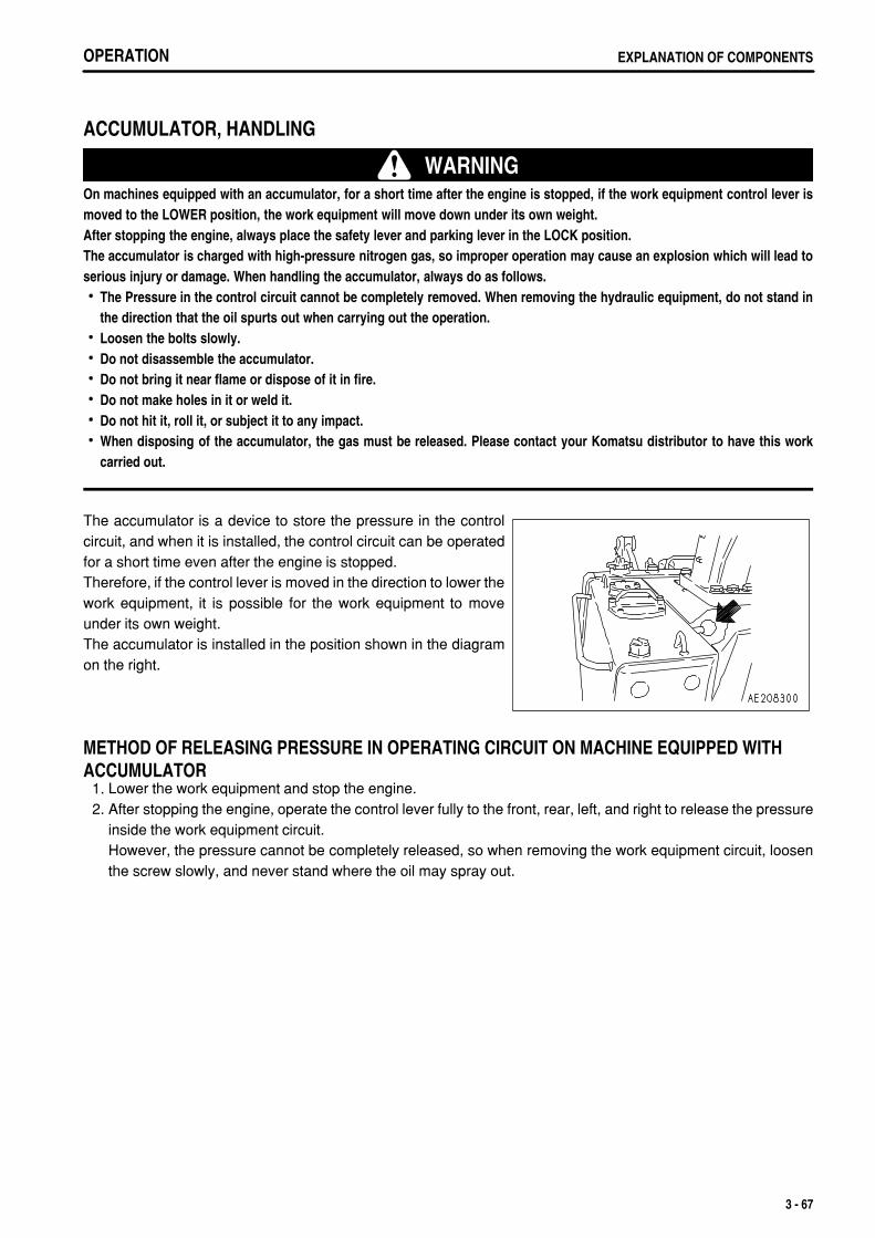
.
OPERATION EXPLANATION OF COMPONENTS
ACCUMULATOR, HANDLING
WARNINGOn machines equipped with an accumulator, for a short time after the engine is stopped, if the work equipment control lever ismoved to the LOWER position, the work equipment will move down under its own weight.After stopping the engine, always place the safety lever and parking lever in the LOCK position.The accumulator is charged with high-pressure nitrogen gas, so improper operation may cause an explosion which will lead toserious injury or damage. When handling the accumulator, always do as follows.
The Pressure in the control circuit cannot be completely removed. When removing the hydraulic equipment, do not stand inthe direction that the oil spurts out when carrying out the operation.Loosen the bolts slowly.Do not disassemble the accumulator.Do not bring it near flame or dispose of it in fire.Do not make holes in it or weld it.Do not hit it, roll it, or subject it to any impact.When disposing of the accumulator, the gas must be released. Please contact your Komatsu distributor to have this workcarried out.
The accumulator is a device to store the pressure in the controlcircuit, and when it is installed, the control circuit can be operatedfor a short time even after the engine is stopped.Therefore, if the control lever is moved in the direction to lower thework equipment, it is possible for the work equipment to moveunder its own weight.The accumulator is installed in the position shown in the diagramon the right.
METHOD OF RELEASING PRESSURE IN OPERATING CIRCUIT ON MACHINE EQUIPPED WITH ACCUMULATOR 1. Lower the work equipment and stop the engine. 2. After stopping the engine, operate the control lever fully to the front, rear, left, and right to release the pressure
inside the work equipment circuit.However, the pressure cannot be completely released, so when removing the work equipment circuit, loosenthe screw slowly, and never stand where the oil may spray out.
3 - 67

.
OPERATIONEXPLANATION OF COMPONENTS
HANDLING MACHINES EQUIPPED WITH VHMSVHMS is a machine management system. When a communications terminal is installed, it is possible to transmitdata.A contract is necessary before the VHMS communications terminal can be used. Any customers desiring to usethe VHMS system should consult their Komatsu distributor.
VHMS INSTALLED, COMMUNICATIONS TERMINAL NOT INSTALLED
BASIC PRECAUTIONS
WARNINGNever disassemble, repair, modify, or move the VHMS or cables. This may cause failure or fire on the VHMS equipment or themachine itself. (Your Komatsu distributor will carry out removal and installation of VHMS.)Do not allow cables or cords to become caught; do not damage or pull cables or cords by force. Short circuits or disconnectedwires may cause failure or fire on the VHMS equipment or the machine itself.
REMARKThere is absolutely no need to inspect or operate the VHMS, but if any abnormality is found, please contact yourKomatsu distributor.
VHMS AND COMMUNICATIONS TERMINAL INSTALLEDThe VHMS communications terminal is a wireless device using radio waves, so it is necessary to obtainauthorization and conform to the laws of the country or territory where the machine equipped with the VHMScommunications terminal is being used. Always contact your Komatsu distributor before selling or exporting anymachine equipped with the VHMS communications terminal.When selling or exporting the machine or at other times when your Komatsu distributor considers it necessary,it may be necessary for your Komatsu distributor to remove the VHMS communications terminal or to carry outaction to stop communications.
If you do not obey the above precautions, neither Komatsu nor your Komatsu distributor can take anyresponsibility for any problem that is caused or for any loss that results.
BASIC PRECAUTIONS
WARNINGNever disassemble, repair, modify, or move the VHMS, communications terminal, antenna, or cables. This may cause failureor fire on the VHMS communications terminal or the machine itself. (Your Komatsu distributor will carry out removal andinstallation of the VHMS and communications terminal.)Do not allow cables or cords to become caught; do not damage or pull cables or cords by force. Short circuits or disconnectedwires may cause failure or fire on the VHMS communications terminal or the machine itself.For anyone wearing a pacemaker, make sure that the communications antenna is at least 22 cm from the pacemaker. The radiowaves may have an adverse effect on the operation of the pacemaker.
NOTICEPlease contact your Komatsu distributor before installing a top guard or other attachment that covers the antenna.Be careful not to get water on the communications terminal or wiring.
3 - 68

.
OPERATION EXPLANATION OF COMPONENTS
REMARKThe communications terminal uses wireless communications, so it cannot be used inside tunnels, underground,inside buildings, or in mountain areas where radio waves cannot be received. Even when the machine is outside,it cannot be used in areas where the radio signal is weak or in areas outside the wireless communication servicearea.There is absolutely no need to inspect or operate the VHMS or communications terminal, but if any abnormalityis found, please contact your Komatsu distributor.
3 - 69

.
OPERATIONOPERATION
OPERATION
CHECK BEFORE STARTING ENGINE, ADJUST
WALK-AROUND CHECKBefore starting the engine, look around the machine and under the machine to check for loose nut and bolts, orleakage of oil, fuel, or coolant, and check condition of the work equipment and hydraulic system. Check also forloose wiring, play, and collection of dust at places which reach high temperatures.
WARNINGLeakage of oil or fuel, or accumulation of flammable material around high temperature parts, such as the engine muffler orturbocharger, may cause fire.Check carefully, and if any abnormality is found, repair it or contact your Komatsu distributor.Do not get on or off the machine from the rear. Using this position is dangerous because it is easy to slip and you cannot beseen from the operator's compartment. Always use the handrail and step at the side when getting on or off the machine.
If the machine is at an angle, make it level before checking.Before starting the engine, look around the machine and under the machine to check for loose nut or bolts, orleakage of oil, fuel, or coolant, and check the condition of the work equipment and hydraulic system. Check also forloose wiring, play, and collection of dust at places which reach high temperatures.Always carry out the items in this section before starting the engine each day.
1. Check for damage, wear, play in work equipment, cylinders, linkage,hosesCheck that there are no cracks, excessive wear, play in work equipment, cylinders, linkage, or hoses. If anyabnormality is found, repair it.
2. Remove dirt and dust from around engine, battery radiator.Check if there is any dirt or dust accumulated around the engine or radiator. Check also if there is any flammablematerial (dead leaves, twigs, grass, etc.) accumulated around the battery or high temperature engine parts,such as the engine muffler or turbocharger. Remove all such dirt or flammable material.
3. Check for leakage of water or oil around engine.Check that there is no leakage of oil from the engine or leakage of water the cooling system. If any abnormalityis found, repair it.
4. Check for leakage of oil from power train case, final drive case, hydraulic tank, hose, jointsCheck that there is no oil leakage. If any abnormality is found, repair the place where the oil is leaking.Check for leakage of oil from the undercover. Check the ground for traces of oil leakage.
5. Check the undercarriage (track, sprocket, idler, guard) for damage, wear, loose bolts, or leakage of oil fromrollersIf any damage, wear, or oil leakage is found, repair the problem and tighten the bolts.
6. Check for damage to handrail and loose boltsRepair any damage and tighten any loose bolts.
3 - 70

.
OPERATION OPERATION
7. Check for damage to gauges, lamps on instrument panel, loose bolts.Check that there is no the panel, gauges, and lamps.If any abnormality is found, replace the parts. Clean off any dirt on the surface.
8. Check for damage to seat belt and mounting clampsCheck that there is no abnormality in the seat belt or mounting clamps. If there is any damage, replace with newparts.
3 - 71

.
OPERATIONOPERATION
CHECK BEFORE STARTINGAlways check the items in this section before starting the engine each day.
CHECK MACHINE MONITOR 1. Turn starting switch (1) to the ON position. 2. Check that the monitor and gauges light for 3 seconds, and the
alarm buzzer sounds for 1 seconds.
REMARKIf the lamps do not light up, there may be a failure or disconnectionin the monitor, please contact your Komatsu distributor.
NOTICEDo not simply use the monitor to carry out the check before starting.Always carry out the check before starting according to the procedure onthe following pages.
3 - 72

.
OPERATION OPERATION
CHECK COOLANT LEVEL, ADD COOLANT
WARNINGNormally, do not open the radiator cap. When checking the coolant level, check the sub-tank when the engine is cold.Do not remove the cap when the radiator coolant is hot. Boiling coolant may spurt out. After the coolant temperature goesdown, turn the cap slowly to release the pressure, then remove it.
1. Open the engine side cover on the left side of the chassis, andcheck that the coolant is between the FULL and LOW marks onsub-tank (1). If the coolant level is low, add coolant to the FULLlevel through the coolant filler port in sub-tank (1).
REMARKThe coolant may overflow from the sub-tank drain hose. This is noproblem. It occurs because too much coolant has been added.
2. After adding coolant, tighten the cap securely. 3. If the sub tank is empty, first check for leakage of water, then
remove radiator cap (2) and check that the coolant water isabove the bottom surface of the strainer as shown in thediagram on the right. Add water if the level is low.
4. After adding coolant, close the engine side cover.
3 - 73

.
OPERATIONOPERATION
CHECK FUEL LEVEL, ADD FUEL
WARNINGWhen adding fuel, never let the fuel overflow. This may cause a fire. If the fuel is spilt, wipe it off completely.
1. Turn the starting switch to the ON position and check the fuellevel with fuel gauge (G) on the monitor panel.After checking, turn the switch back to the OFF position.
2. After completing work, fill the fuel tank through fuel filler port(F).Check the fuel level with the fuel gauge at the fuel filler port.
3. After adding fuel, tighten the cap securely.Fuel capacity: 1670 liters (441.21 US gal)
REMARKWhen dozing on a grade, make sure there is plenty of fuel in thetank so that the engine fuel line does not become aerated.If breather hole (1) on the cap is clogged, the pressure in thetank will drop and fuel will not flow.Clean the hole from time to time.
3 - 74
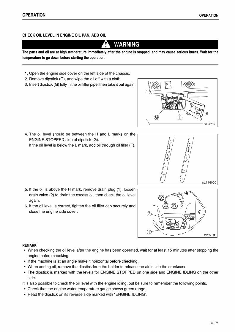
.
OPERATION OPERATION
CHECK OIL LEVEL IN ENGINE OIL PAN, ADD OIL
WARNINGThe parts and oil are at high temperature immediately after the engine is stopped, and may cause serious burns. Wait for thetemperature to go down before starting the operation.
1. Open the engine side cover on the left side of the chassis. 2. Remove dipstick (G), and wipe the oil off with a cloth. 3. Insert dipstick (G) fully in the oil filler pipe, then take it out again.
4. The oil level should be between the H and L marks on theENGINE STOPPED side of dipstick (G).If the oil level is below the L mark, add oil through oil filler (F).
5. If the oil is above the H mark, remove drain plug (1), loosendrain valve (2) to drain the excess oil, then check the oil levelagain.
6. If the oil level is correct, tighten the oil filler cap securely andclose the engine side cover.
REMARKWhen checking the oil level after the engine has been operated, wait for at least 15 minutes after stopping theengine before checking.If the machine is at an angle make it horizontal before checking.When adding oil, remove the dipstick form the holder to release the air inside the crankcase.The dipstick is marked with the levels for ENGINE STOPPED on one side and ENGINE IDLING on the otherside.
It is also possible to check the oil level with the engine idling, but be sure to remember the following points.Check that the engine water temperature gauge shows green range.Read the dipstick on its reverse side marked with "ENGINE IDLING".
3 - 75

.
OPERATIONOPERATION
CHECK OIL LEVEL IN POWER TRAIN CASE (INCL. TRANSMISSION, TORQUE CONVERTER AND BEVEL GEAR CASES), ADD OIL
WARNINGThe undercover is heavy. Do not go directly under the cover when opening or closing it. When removing bolts (5), carry out theoperation at the rear of the point immediately under the cover so that it is possible to escape at any time.
1. Start the engine and run at idling for 5 minutes, then check theoil level with the COLD side of dipstick (G).Remove dipstick (G), and wipe the oil off with a cloth.
2. Insert dipstick (G) fully in the oil filler pipe, then take it out again. 3. The oil level should be between the H and L marks on dipstick
(G).If the oil level is below the L mark, add oil through oil fillerport(F).
4. If the oil level is above the H line, drain oil as follows. 1) Remove 2 bolts (4) at the front of the machine. 2) Hold down the cover (3) and gradually remove 2 bolts (5)
at the rear of the machine. 3) Cover (3) is fitted with a hinge pin at the front, so gradually
lower cover (3).
3 - 76

.
OPERATION OPERATIONOPERATION OPERATION
4) Remove hose (1), loosen drain valve (2) and drain theexcess oil, then check the oil level.
5) If the oil level is correct, tighten the oil filler cap securely.
REMARKWhen checking the oil level, if the machine is at an angle, move it to a horizontal position before carrying out thecheck.When checking the oil level before starting operations, check with the engine stopped and use the dipstick COLDSTOP side. It is also possible to check the oil level after the engine has been run and the power train oiltemperature is high, but in this case, run the engine at idling and use the dipstick HOT IDLING side.
CHECK BRAKE PEDAL TRAVELDrive the machine, depress the brake pedal, and check that the machine stops.
CHECK DUST INDICATOR 1. Check for the yellow piston overlapping the red zone on the
dust indicator (1). 2. If the yellow piston is overlapping the red zone, clean or
replace the element immediately.For details of the method of cleaning the element, see"CHECK, CLEAN AND REPLACE AIR CLEANER ELEMENT(PAGE 4-25)".
3. After checking, cleaning, and replacing, press the knob of dustindicator (1) to return the yellow piston to its original position.
In environments where the rubber deteriorates quickly or thesurface becomes damaged (in direct sunlight, dusty areas,etc.), replace before it becomes dirty and it becomes difficultto judge the condition.
3 - 77

.
OPERATIONOPERATION
CHECK OIL LEVEL IN HYDRAULIC TANK, ADD OIL
WARNINGWhen removing the oil filler cap, oil may spurt out, so stop the engineand wait for the oil temperature to go down, then turn the cap slowly torelease the internal pressure before removing the cap.If oil has been added to above the H mark, stop the engine and wait forthe hydraulic oil to cool down. Then remove drain plug (P), loosen drainvalve (1), and drain the excess oil.
1. Lower blade to the ground and stop the engine. Wait forapprox. 5 minutes before checking oil level. Oil level should bebetween the H and L in sight gauge (G).
NOTICEIf the oil level is above the H line, do not add oil. Doing so may lead todamage to the oil pressure circuit and spouting out of oil.
2. If the level is below the L mark, add oil through oil filler (F).
REMARKWhen inspecting, if the machine is at an angle, move it to a levelplace to carry out the check.
3 - 78

.
OPERATION OPERATION
CHECK ELECTRIC WIRING
WARNINGIf fuses are frequently blown or if there are traces of short circuit on the electrical wiring, locate the cause and carry out repair,or please contact your Komatsu distributor.Accumulation of flammable material (dead leaves, twigs, grass, etc.) around the battery may cause fire, so always check andremove such material.Keep the top surface of the battery clean and check the breather hole in the battery cap. If it is clogged with dirt or dust, washthe battery cap to clear the breather hole.
Check that there is no damage to the fuse, that a fuse of the specified capacity is being used, that there are no signsof any disconnection, breakage, or short circuit in the electric wiring, check for any loose terminals, and tighten anyloose terminals that are found.Be particularly careful to check the wiring for the battery, starting motor, and alternator.In addition, if any flammable material is accumulated around the battery, remove it. For repairs or investigation of the cause, please contact your Komatsu distributor.
CHECK THAT LAMPS LIGHT UP 1. Turn the starting switch key to the ON position.
2. Turn the front lamp and working lamp switch to the ON (b)position and check that the front lamps and working lamp lightup.
3. Turn the rear lamp switch to the ON (b) position and check thatthe rear lamps on the left and right fenders light up.If the lamps do not light up, there is probably a broken bulb ordisconnected in the wiring, so contact your Komatsu distributorfor repairs.
3 - 79

.
OPERATIONOPERATION
CHECK HORN SOUND 1. Turn the starting switch key to the ON position.
2. Push the horn switch and check that the horn sounds.
CHECK BACKUP ALARM SOUND 1. After starting the engine, run it at idling, depress the brake to
the fullest extent, and set the parking lever free.
2. While depressing the brake pedal to the fullest extent, set thejoystick to the REVERSE position. The buzzer must soundimmediately. The buzzer will continue to sound until thejoystick is moved to the NEUTRAL or FORWARD position.
3. As soon as it is confirmed that the buzzer is working properly,set the joystick to the NEUTRAL position, put the parking leverto the LOCK position, and then release the brake pedal.
3 - 80

.
OPERATION OPERATION
ADJUSTMENT
ADJUSTING OPERATOR'S SEAT
WARNINGAdjust the seat position at the beginning of each shift or when operators change.Adjust the seat so that the brake pedal can be depressed all the way with the operator's back against the backrest.
(A) Fore-and-aft adjustmentPull lever (1), set the seat to a position where it is easy to operate,then release the lever.Fore-aft adjustment: 200 mm (7.9 in) (10 stages)
(B) Weight and height adjustment of seatTurn knob (2) under the seat so that weight adjustment indicator(3) displays the green range. The height can be adjusted byturning the knob (2) while the green range is displayed.Turn the knob clockwise to raise the seat and turn the knobcounterclockwise to lower the seat.
Height adjustment range: stepless, 75 mm (3 in)Weight adjustment range: 50 to 130 kg (110 to 237 lb)
(C) Adjust reclining angle
REMARKWhen the seat is pushed forward, the available reclining angle becomes greater; when the seat is pushed back, theavailable reclining angle becomes smaller. When moving the backrest, return the backrest to its original positionbefore moving the seat.
Pull up lever (4), set the seatback to a position where it is easy to operate, then release the lever.
(D) Adjusting direction of seatPull up lever (5) to unlock the seat. The seat can then be turned 15° to the right.After changing the direction of the seat, return the lever securely tolock the seat.
Change the direction of the seat to the right for the ease ofoperation of the ripper.
REMARKIf the direction of the seat is changed, the steering, directional, andgearshift lever is also interconnected and changes direction.
3 - 81

.
OPERATIONOPERATION
USING SEAT BELTAlways install a seat belt on machines equipped with ROPS.
WARNINGBefore fastening the seat belt, inspect the securing brackets and belt for abnormal conditions.Replace any worn or damaged seat belt or the securing brackets.Even no problem can be seen with the belt, always replace the seatbelt once every three years. The date of manufacture isgiven on the rear side of the belt.Adjust and fasten the seat belt before operating the machine.Always use the seat belt when operating the machine.Fit the seat belt across your lap without twisting.
FASTEN THE BELT AND REMOVE IT 1. Sit on the seat, depress the brake pedal fully, and adjust the
seat so that your back is pressed against the backrest. 2. After adjusting the seat position, adjust tether belt (1). Tense
the tether belt and install it when there is no one sitting on theseat.
3. Sit on the seat and hold tongue (4) connected to wind-inmechanism (2) and pull out the belt slowly so that the belt willcover your abdomen sufficiently.
4. Insert tongue (4) in buckle (3) until it clicks. The belt is pulledback into wind-in mechanism (2) until it is fitted to yourabdomen. The belt is locked under this condition and cannotbe extended anymore. Fit the belt to your abdomen withouttwisting it.
REMARKIf the belt is locked before the tongue is inserted in the buckle, letit return to the wind-in mechanism, then repeat the aboveprocedure from the start.
5. Pull the belt to check that it is securely locked in position. 6. When removing the belt, press the red button on buckle (3).
The belt will automatically retract.Check that the bolts of the clamp securing the belt to the chassis are not loose. Tighten them if they are loose.Tightening torque: 24.5 ± 4.9 Nm (2.5 ± 0.5 kgm, 18.1 ± 3.6 lbft)If the seat belt is scratched or frayed, if any fittings are broken or deformed from long service, replace the seat beltimmediately.
3 - 82

.
OPERATION OPERATION
ADJUST MIRRORLoosen nut (1) of the mirror and adjust the mirror to a positionwhere it gives the best view from the operator's seat.In particular, be sure to adjust the mirror so that people at the rearleft or right of the machine can be seen clearly.
ADJUST JOYSTICK (PCCS LEVER)
WARNINGAfter moving case (2) in order to adjust the position of the steering, directional, and gearshift lever, check that lock lever (1) isfitted securely in the notch hole when securing it. Check that it is in the LOCK position. If the lock condition is not complete, thesteering, directional, and gearshift lever may move at an unexpected time and cause serious injury or damage.
The steering, directional, and speed lever (wrist control type single lever: joystick) can be adjusted by 100 mm (3.9in) in 5 stages to the front or rear. Adjust to the most suitable position to match the adjustment of the operator's seat. 1. Pull up lock lever (1) at the rear of case (2) on the left side of the
operator's compartment and make it free.
2. Keep lock lever (1) pulled up and use your other hand to gripthe front of case (2), then move it to the front with your left andright hands. The joystick moves together with the case.
3. When moving, set to the desired position of the positionswhere a click can be heard. Then pull up lock lever (1) andrelease it. Lock lever (1) returns automatically to the LOCKposition.
REMARKPCCS: Palm command control system
3 - 83

.
OPERATIONOPERATION
ADJUST ARMRESTThe height of the armrest on the left and right sides of the operator's seat can be adjusted to 3 positions. Afteradjusting the operator's seat, adjust the armrest to a suitable height.
ADJUST ARMREST (RIGHT)Armrest (1) on the right side of the operator's cab part can be adjusted up 30 mm (1.2 in) or down 30 mm (1.2 in)based on the standard height (center) in three stages. 1. Loosen knob (2) (2 places).
2. Move the armrest on the operator's seat to the front, then alignthe position of the 3 holes (high, middle, low).
3. Tighten knob (2) securely.
ADJUST ARMREST (LEFT)The armrest on the left side of the operator's compartment can be adjusted to 2 heights.
1. When adjusting height of both armrest and caseIt is possible to adjust the standard height up 50 mm (2.0 in) ordown 50 mm (2.0 in) steplessly.The steering, directional, and gearshift lever moves as a unit.Turn up/down left adjustment knob (1) to adjust the height.Turn the knob to adjust as follows.Turn CLOCKWISE to move UPTurn COUNTERCLOCKWISE to move DOWN
3 - 84

.
OPERATION OPERATIONOPERATION OPERATION
2. When adjusting height of armrest onlyIt is possible to adjust steplessly up to 36 mm (1.4 in) up fromthe armrest and case contact surface.The steering, directional, and gearshift lever does not move.
Open the armrest, and turn counterclockwise knob (2) to adjustthe height.Only the armrest will move up. After adjusting it to the desiredheight, close the armrest.
3. By carefully adjusting to match the operator's physique, it ispossible to operate the travel lever correctly (with fine controland smooth steering) and comfortably (with little fatigue), soadjust the armrest as follows: 1) Sit in the operator's seat, grip the travel lever, and turn
up-down adjustment knob (1) to adjust the height of theconsole assembly to a position where the elbow matchesthe top surface of the armrest as shown in the diagram onthe right.
2) Next, operate the travel lever to the left and right, and turnknob (2) to adjust the height of the armrest to match thethickness of the operator's arm so that it is possible tooperate smoothly to the left and right using the elbow andthe support at the front.
3 - 85

.
OPERATIONOPERATION
OPERATIONS AND CHECKS BEFORE STARTING ENGINE
WARNINGWhen starting the engine, check that the safety lock lever and parkinglever is securely at the LOCK position.If the control levers are not locked and they are touched by accidentwhen starting the engine, the work equipment may move unexpectedly,and this may lead to a serious injury or death.When standing up from the operator's seat, always set the safety locklever to the LOCK position, regardless of whether the engine is runningor stopped.
1. Check that parking lever (1) is locked. If this lever is not in theLOCK position, the engine will not start.
2. Check that joystick (2) is in the N (neutral) position.
3 - 86

.
OPERATION OPERATIONOPERATION OPERATION
3. Check that the blade is lowered to the ground and that bladecontrol lever (3) is in the HOLD position. If it is in the FLOATposition, the engine will not start.
4. Check that the ripper is lowered to the ground. 5. Check that work equipment lock lever (4) is locked.
If work equipment lock lever (4) is locked, the blade controllever is returned to the HOLD position even if it is in the FLOATposition.
3 - 87

.
OPERATIONOPERATION
STARTING ENGINE
NORMAL STARTING
WARNINGCheck that there are no persons or obstacles in the surrounding area,then sound the horn and start the engine.Exhaust gas is toxic. When starting the engine in confined spaces, beparticularly careful to ensure good ventilation.
NOTICEDo not keep the starting motor rotating continuously for more than 20seconds.If the engine will not start, wait for at least 2 minutes before trying to startthe engine again.
1. Turn fuel control dial (1) a little toward you from the MINposition.
2. Turn the key of starting switch (2) to the START position.
3. When engine is started, release the key of starting switch (2)and the key will return automatically to ON.
3 - 88
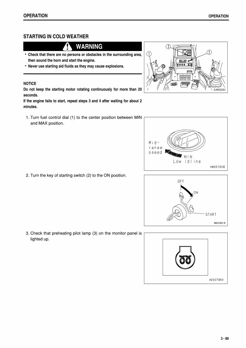
.
OPERATION OPERATION
STARTING IN COLD WEATHER
WARNINGCheck that there are no persons or obstacles in the surrounding area,then sound the horn and start the engine.Never use starting aid fluids as they may cause explosions.
NOTICEDo not keep the starting motor rotating continuously for more than 20seconds.If the engine fails to start, repeat steps 3 and 4 after waiting for about 2minutes.
1. Turn fuel control dial (1) to the center position between MINand MAX position.
2. Turn the key of starting switch (2) to the ON position.
3. Check that preheating pilot lamp (3) on the monitor panel islighted up.
3 - 89

.
OPERATIONOPERATION OPERATIONOPERATION
4. Keep in this condition until engine pre-heating pilot lamp (3)goes out.(Pre-heating is completed after approx. 12 seconds, and thelamp goes out.)
5. When preheating pilot lamp (3) goes out, turn the key instarting switch (2) to the START position to start the engine.The time that preheating pilot lamp (3) stays on changesaccording to the ambient temperature as shown in the tablebelow.
Ambient temperature Preheat time
0°C to -10°C (32°F to 14°F) 0 to 15 seconds
-10°C to -20°C�(14°F to -4°F) 15 to 30 seconds
-20°C to -30°C (-4°F to -22°F) 30 to 50 seconds
6. When the engine is started, release the key of starting switch(2) and the key will return automatically to ON.
7. When the engine rotation stabilizes, return to the low idle (MIN) position of fuel control dial (1) and then carry outthe warming-up operation.
REMARKRegardless of the ambient temperature, if the key in starting switch (2) is turned from OFF position to left,preheating pilot lamp (3) will light up and preheating will start. (Preheating continues while the starting switch isheld at the left.)For the details of the preheating time, see the table in Step 5.While preheating is being carried out, the preheating pilot lamp (3) lights up to show that preheating is beingcarried out. After it lights up for 36 seconds, it flashes for 16 seconds and goes out. When it goes out, completethe preheating immediately.If the engine does not start with the above operation, wait for about 2 minutes, and repeat steps from Step 3. And4.
3 - 90

.
OPERATION OPERATION
OPERATIONS AND CHECKS AFTER STARTING ENGINE
WARNINGIf there has been any Emergency stop, abnormal actuation or trouble, turn the starting switch key to the OFF position.If the work equipment is operated without sufficiently warming the machine up, response of the work equipment to movementof the control lever will be slow, and the work equipment may not respond as the operator desires, so always perform thewarming-up operation. Particularly in cold areas, be sure the warming-up operation is completed.
BREAKING IN THE MACHINE
CAUTIONYour Komatsu machine has been thoroughly adjusted and tested before shipment. However, operating the machine under severeconditions at the beginning can adversely affect the performance and shorten the machine life.Be sure to break-in the machine for the initial 100 hours (as indicated by the service meter).During break-in operations, follow the precautions described in this manual.
Run the engine at idle for 15 seconds after starting it. During this time, do not operate the control levers or fuelcontrol dial.Idle the engine for 5 minutes after starting it up.Avoid operation with heavy loads or at high speeds.Immediately after starting the engine, avoid sudden starts, sudden acceleration, unnecessary sudden stops, andsudden changes in direction.
WARMING UP OPERATIONSNOTICE
Do not perform operations or suddenly operate the levers when thehydraulic oil is at a low temperature. Always perform the warming-upoperation until the hydraulic oil temperature monitor displays the greenrange. This will help extend the machine life.Do not suddenly accelerate the engine before the machine reaches fulloperating temperature.Do not run the engine at low or high idle for more than 20 minutes. Thiswill cause oil leaks from the turbocharger oil supply piping.If it is necessary to run the engine at idling, apply a load from time totime or run the engine at a mid-range speed.If engine oil pressure caution lamp (3) flashes or the buzzer soundsintermittently, stop the engine and check for the cause.
3 - 91

.
OPERATIONOPERATION OPERATIONOPERATION
1. Turn fuel control dial (1) to the center position between lowidling (MIN) and high idling (MAX) positions and run the engineat a mid-range speed for 5 minutes under no load.
2. After warm-up is completed, check gauges and caution lampsfor proper operation. If any problem is found, repair it.Continue to run the engine under a light load until enginecoolant temperature gauge indicator (2) is within the greenrange (B).(A): White range(B): Green range(C): Red range
3. Check for abnormal exhaust gas color, noise, or vibration. If any problem is found, contact your Komatsudistributor.
3 - 92

.
OPERATION OPERATION
IN COLD AREAS 1. Turn fuel control dial (1) to the center position between low
idling (MIN) and high idling (MAX) positions and run the engineat a mid-range speed for 10 minutes under no load.
2. Operate blade control lever (4) to the RAISE position, thenkeep the blade raised to the maximum height and continue torelieve the circuit for 10 minutes.
3. Finally, operate blade control lever (4) and ripper control leverto operate the blade and ripper cylinders several times.If the oil temperature in the work equipment is not properlyraised, there will be a time lag in the response of the workequipment and steering.
4. After warm-up is completed, check gauges and caution lampsfor proper operation. If any problem is found, repair it.Continue to run the engine under a light load until enginecoolant temperature gauge indicator (2) is within the greenrange (B).(A): White range(B): Green range(C): Red range
REMARKIf the power train oil temperature is not raised sufficiently, it will takelonger to accelerate to the maximum speed.
5. Check for abnormal exhaust gas color, noise, or vibration. If any problem is found, contact your Komatsudistributor.
3 - 93
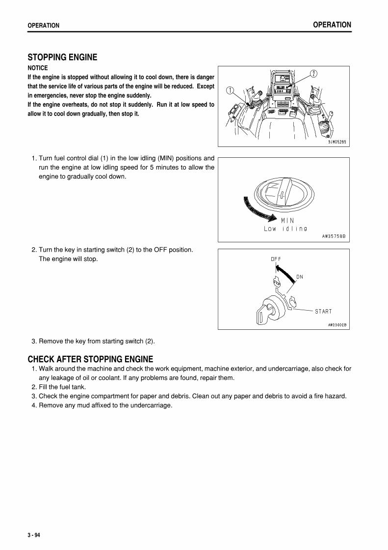
.
OPERATIONOPERATION
STOPPING ENGINENOTICEIf the engine is stopped without allowing it to cool down, there is dangerthat the service life of various parts of the engine will be reduced. Exceptin emergencies, never stop the engine suddenly.If the engine overheats, do not stop it suddenly. Run it at low speed toallow it to cool down gradually, then stop it.
1. Turn fuel control dial (1) in the low idling (MIN) positions andrun the engine at low idling speed for 5 minutes to allow theengine to gradually cool down.
2. Turn the key in starting switch (2) to the OFF position.The engine will stop.
3. Remove the key from starting switch (2).
CHECK AFTER STOPPING ENGINE 1. Walk around the machine and check the work equipment, machine exterior, and undercarriage, also check for
any leakage of oil or coolant. If any problems are found, repair them. 2. Fill the fuel tank. 3. Check the engine compartment for paper and debris. Clean out any paper and debris to avoid a fire hazard. 4. Remove any mud affixed to the undercarriage.
3 - 94

.
OPERATION OPERATION
MOVING MACHINE
WARNINGBefore moving the machine, check that the area around the machine issafe, and always sound the horn before moving.Do not allow anyone to enter the area around the machine.The rear of the machine is a blind spot, so be extremely careful whentraveling in reverse.When moving the machine down a slope, always keep brake pedal (8)depressed, even after releasing parking brake lever (1).When moving the machine up a steep slope, turn fuel control dial (5) tohigh idling (MAX) position and run the engine at full speed, and keepbrake pedal (8) and decelerator pedal (6) depressed. Then operatesteering, directional, and gearshift lever (4) from the N (neutral) positionto the direction of travel and slowly release brake pedal (8). When thetravel speed rises, slowly release decelerator pedal (6).
1. Set parking brake lever (1) to the FREE position.
2. Set work equipment lock lever (2) for blade control lever (3)and ripper control lever (4) to the FREE position.
3 - 95

.
OPERATIONOPERATION OPERATIONOPERATION
3. Operate blade control lever (3) and ripper control lever (4) tothe RAISE position, raise the blade 40 - 50 cm (15.8 - 19.7 in)from the ground, and raise the ripper to the maximum height.
4. Turn fuel control dial (5) to the full speed (MAX) position, raisethe engine speed, and fully depress decelerator pedal (6).
5. Move joystick to the F (FORWARD) or R (REVERSE) position,gradually release decelerator pedal (6) and allow the machineto move.
3 - 96

.
OPERATION OPERATION
STOPPING MACHINE
WARNINGAvoid stopping suddenly. Give yourself ample room when stopping.When stopping the machine, select flat hard ground and avoiddangerous places. If it is unavoidably necessary to park the machine ona slope, place the parking brake lever (1) in the LOCK position and insertblocks underneath the track shoes. As an additional safety measure,thrust the blade into the ground.If the work equipment control lever is touched by accident, the workequipment may suddenly move, and may cause damage, serious injury,or death. Before leaving the operator's seat, always secure workequipment lock lever (2) in the LOCK position.
1. Depress brake pedal (3) to apply the brake.
NOTICEIf the brake is depressed when the engine speed or travel speed is high, thebrake disc may make a slipping sound. Normally, depress deceleratorpedal (4) to reduce the engine speed and travel speed before depressingthe brake.
2. Set joystick (5) in the neutral position.
3 - 97

.
OPERATIONOPERATION
SHIFTING GEARThe machine does not have to be stopped to shift gears. 1. Move steering, forward-reverse, gear shift lever (1) to the
desired gear position to shift gears.
GEAR SHIFTINGWhen the joystick is at the FORWARD or REVERSE positionand switch (a) or switch (b) is pushed, the transmission speedwill change.UP switch (a): Each time the switch is pressed, the transmissionwill shift up one speed.DOWN switch (b): Each time the switch is pressed, thetransmission will shift down one speed.
When the lever is moved to the forward (to set to FORWARD) from the N position, the transmission shifts to F1.If the UP switch is pressed once when the transmission is in F1, the transmission shifts to F2.If the UP switch is pressed once when the transmission is in F2, the transmission shifts to F3.If the DOWN switch is pressed once when the transmission is in F3, the transmission shifts to F2.If the DOWN switch is pressed once when the transmission is in F2, the transmission shifts to F1.When the lever is moved to the rear (to set to REVERSE) from the N position, the transmission shifts to R1.If the UP switch is pressed once when the transmission is in R1, the transmission shifts to R2.If the UP switch is pressed once when the transmission is in R2, the transmission shifts to R3.If the DOWN switch is pressed once when the transmission is in R3, the transmission shifts to R2.If the DOWN switch is pressed once when the transmission is in R2, the transmission shifts to R1,
For details of the maximum speed in each speed range, see "SPECIFICATIONS (PAGE 5-2)".
REMARKThe speed range in use is displayed on the panel display accordingto the gearshift operation.For example:Neutral: N is displayed on the display panel A (2)FORWARD 2nd: F2 is displayed on the display panel A (2)REVERSE 3rd: R3 is displayed on the display panel A (2)When the parking brake lever is locked, P is displayed.
3 - 98

.
OPERATION OPERATION
GEARSHIFTING USING SHIFT MODE SELECTIONShift mode selection means that the selected speed range is displayed in the N position before starting.When the joystick is in the N position, if UP switch (a) or DOWNswitch (b) is pressed, the shift mode selection can be carriedout.
The selected shift mode is displayed on display panel B(multi-information) of the monitor panel.
Shift operation when [F1-R2] mode is setWhen the steering, directional, and speed lever is in the N position, if the up switch is pressed once, the modeis set to [F1-R2] mode. After that, if the steering, directional, and speed lever is operated forward (forward traveloperation), the transmission is shifted to F1. If it is moved back (reverse travel operation), the transmission isshifted to R2.
Shift operation when [F2-R2] mode is setWhen the steering, directional, and speed lever is in the N position, if the up switch is pressed twice, the modeis set to [F2-R2] mode. After that, if the steering, directional, and speed lever is operated forward (forward traveloperation), the transmission is shifted to F2. If it is moved back (reverse travel operation), the transmission isshifted to R2.
REMARKEven when the transmission is set to [F1-R1] mode, [F1-R2] mode, or [F2-R2] mode, if the UP switch or DOWNswitch is operated, this will be given priority and manual operation can be carried out.For example:After the [F1-R2] mode has been set, if the joystick is operated forward (to set to FORWARD), the speed range isset to F1. However, if the lever is kept operated forward and UP switch (a) is pressed once, the speedrange will shift to F2; if the UP switch is pressed twice, the speed range will shift to F3. When the transmission isin F3 and DOWN switch (b) is pressed once, the speed range will shift to F2; if the DOWN switch is pressed twice,the speed range will shift to F1.On the other hand, if the joystick is operated to the rear (to set to REVERSE), the speed range is automaticallyswitched R1 → R2. However, if the lever is kept operated to the rear and UP switch (a) is pressed once,the speed range will shift to R3; if the DOWN switch (b) is pressed once, the speed range will shift to R1.However, the setting stays in the [F1-R2] mode. If the steering, directional, and gearshift lever is returned to N andthen operated forward (to set to FORWARD), the speed range is set to F1; if the lever is operated to the rear (to setto REVERSE), the speed range is automatically switched R1 → R2.
3 - 99

.
OPERATIONOPERATION
REMARKThe default setting is [F1-R1].After the starting switch is turned OFF, the shift mode returns to the default setting [F1-R1].
AUTO SHIFT DOWN OPERATIONIf the travel speed has gone down because of the load conditionwhen traveling, the transmission is automatically shifted to lowspeed. Set auto shift down switch (2) on the instrument panel infront of the operator's seat to the b (ON) position to actuate the autoshift.
OFF position (a): Automatically canceledON position (b): Automatically shifted down to lower speed range
The transmission is automatically shifted down F2→ F1, F3 → F2, R2 → R1, R3 → R2.
REMARKFor safety reasons, during auto shift down, the transmission isprevented from shifting up.
If it is desired to shift up, use manual control and press the UPbutton on the steering, directional, and gearshift lever.
3 - 100

.
OPERATION OPERATION
SHIFTING BETWEEN FORWARD AND REVERSE
WARNINGWhen switching between FORWARD and REVERSE, first check that thedirection of travel is safe.
CAUTIONThere is no need to stop the machine even when switching betweenFORWARD and REVERSE.To increase safety, operator comfort, and the life of the transmission, leavethe engine running at full speed, and always depress the decelerator pedalto lower the engine speed.
1. Depress decelerator pedal (1) to reduce the engine speed.
2. Move joystick (2) to the neutral position, reduce the speed,then depress brake pedal (3) and stop the machine.
3. After depressing decelerator pedal (1), move steering,forward-reverse, gear shift lever (2) to the desired position.
3 - 101

.
OPERATIONOPERATION OPERATIONOPERATION
4. Release decelerator pedal (1) and raise the engine speed.
REMARKWhen the joystick is placed in REVERSE, the backup alarm willsound.
3 - 102

.
OPERATION OPERATION
STEERING MACHINE
WARNINGAvoid as much as possible turning the machine on a slope.The machine will tend to slip sideways. Particular care should be taken on soft or clay soil.Never make a pivot turn at high speed.
NORMAL TURNINGTo turn the machine while traveling, incline steering,forward-reverse, gear shift lever (1) in the direction of the turn.
TURNING GRADUALLY TO LEFT WHILE TRAVELING FORWARDIf the joystick is pushed forward and moved partially to the left (L),the steering clutch is disengaged and the machine turns graduallyto the left.
When turning gradually to the right, push the joystick forward, andmove it partially to the right.Do the same when traveling in reverse.
3 - 103

.
OPERATIONOPERATION
MAKING SHARP TURNS TO LEFT WHILE TRAVELING FORWARDIf the joystick is pushed forward and moved fully to the left (L), thesteering clutch is disengaged, the brake is applied, and themachine turns sharply to the left.
REMARKWhen making sharp turns to the right, push the joystick forward,and move it fully to the right.Do the same when traveling in reverse.
3 - 104

.
OPERATION OPERATION
TURNING WHILE DESCENDING A SLOPEWith machines that can carry out counter rotation turns, on steep downhill slopes where the machine may travelunder its own weight, or on downhill slopes where it is being pushed by a towed machine, the machine will not steerin the opposite direction, so do as follows.
REMARKCross steering means the phenomenon that the machine turns in the opposite direction to the actual steeringdirection.
TURNING GRADUALLY TO LEFT WHILE TRAVELING FORWARDIf the joystick (1) is pushed forward and moved partially to the left(L), the machine turns gradually to the left.
REMARKWhen making gradual turns to the right, push the joystick (1)forward, and move it partially to the right.Do the same when traveling in reverse.
3 - 105

.
OPERATIONOPERATION
MAKING SHARP TURNS TO LEFT WHILE TRAVELING FORWARDOperate the steering, directional, and gearshift lever forward andfully to the left (L). The machine will turn to the left.
REMARKTo make spin turns to the right, operate the steering, directional,and gearshift lever forward and fully to the right. The machine willturn to the right.The same conditions apply when traveling in reverse.
3 - 106

.
OPERATION OPERATION
PRECAUTIONS FOR OPERATION
PAY ATTENTION TO GAUGESIf the red range of the power train oil temperature gauge lights up during operation, reduce the load and wait for thetemperature to go down.
PERMISSIBLE WATER DEPTHWhen operating in water, always keep top surface of the trackframe above the surface of the water.Also, be careful that the engine cooling fan will not come in contactwith water. The fan can be damaged.
PRECAUTIONS WHEN TRAVELING FOR A LONG TIMEAvoid operating the machine at high speed for a long time,otherwise the temperature of hydraulic oil sharply rises, and thatcan cause oil leakage from the track rollers or final drive and lowerdurability.If there is no way to avoid operating the machine at high speed fora long time, stop the machine every one hour for 30 minutes andlet the track rollers and final drive cool off before starting up themachine again.
PRECAUTIONS WHEN TRAVELING UP OR DOWN HILLS
METHOD OF USING DECELERATOR PEDALWhen stepping on the decelerator pedal while going uphill, climbing ability will be reduced and the machine will stop.Furthermore, the engine may stall.
USE ENGINE AS BRAKEWhen going downhill, move steering, forward-reverse, gear shift lever into low speed to run engine at slow speedand travel down slope using the engine as a brake.Do not move the steering, forward-reverse, gear shift lever to the NEUTRAL position.When traveling down hills of more than 15°, shift down to 1st speed (R1 or F1).
BRAKING WHEN TRAVELING DOWNHILLWhile descending a slope using the engine as a brake, also apply the brakes.Failure to brake may result in overrunning, causing engine trouble.
3 - 107

.
OPERATIONOPERATION
PRECAUTIONS ON SLOPE
BE CAREFUL OF FUEL LEVELIf the fuel level in the fuel tank becomes low when working on slopes, the engine may suck in air because of the angleof the machine or the swaying of the machine. This makes the engine stop, so be careful not to let the fuel level inthe fuel tank become too low.
BE CAREFUL OF OIL LEVELWhen operating machine on sloped areas of more than 20°, fill all appropriate components with oil to H level.
PRECAUTIONS WHEN ENGINE STOPS ON SLOPEIf the engine stops while working or traveling on a hill, immediately depress the brake pedal to bring the machine toa complete stop.
METHOD OF USING BRAKESThe following actions cause premature damage to the brakes, so avoid such operations.
Using emergency brake at full speedUsing brake with engine running at full speed in first gear (F1, R1) (Machine stall condition)
REMARKAlways depress the decelerator pedal to lower the engine speed before actuating the brakes.
PROHIBITED TO KEEP THE DOOR OPEN DURING OPERATIONSAlways keep the door closed when traveling or carrying out operations.If the door is open, there is danger of damage from obstacles or strong vibration.
IT IS PROHIBITED TO MODIFY THE CAB GLASS IN ANY WAY THAT WILL OBSTRUCT THE VIEW
For safety reasons, do not install anything on the cab glass that will obstruct the view.Always keep the glass clean to ensure safety during operations.
PRECAUTIONS FOR BLIND SPOTS CAUSED BY CAB STAY AND ROPS STAY
WARNINGThe cab stay and ROPS stay cause blind spots.When operating, always be sure to check carefully that there is no obstacleor worker in the surrounding area.
3 - 108

.
OPERATION OPERATION
PARKING MACHINE
WARNINGAvoid stopping suddenly. Give yourself ample room when stopping.When stopping the machine, select flat hard ground and avoiddangerous places. If it is unavoidably necessary to park the machine ona slope, place the parking lever in the LOCK position and insert blocksunderneath the track shoes. As an additional safety measure, thrust theblade into the ground.If the work equipment control lever is touched by accident, the workequipment may move suddenly, and this may lead to a serious accident.Before leaving the operator's seat, always operate the safety lever toplace it securely at the LOCK position.
1. Depress brake pedal (1) to stop the machine.
NOTICEIf the brake is depressed when the engine speed or travel speed is high, thebrake disc may make a slipping sound. Normally, depress deceleratorpedal (3) to reduce the engine speed and travel speed before depressingthe brake.
2. Set joystick (2) at the neutral position.
3 - 109

.
OPERATIONOPERATION OPERATIONOPERATION
3. Operate parking lever (4) to lock the brakes.
4. Operate blade control lever (5) and ripper control lever (6) tothe LOWER position, and lower the blade and ripper to theground.
5. Set blade control lever (5) and ripper control lever (6) to theHOLD position.
6. Set work equipment lock lever (7) for blade control lever (5)and ripper control lever (6) to the FREE position.
3 - 110

.
OPERATION OPERATION
CHECK AFTER FINISHING WORKUse the meters and caution lamps to check the engine coolanttemperature, engine oil pressure, fuel, and power train oiltemperature.
LOCKINGTo prevent vandalism, there are locks in the following places.Places that can be locked with the starting switch key.
Right and left engine side cover (1)(left side: 2 places, right side: 2 places)Fresh air filter inspection cover (left) (2)Cab door opener (3)Lock-type caps (4) (if equipped)
Radiator capFuel tank capHydraulic tank capPower train oil filler pipe cap
Battery inspection cover(5), (6)Tool box inspection cover (2)
REMARKIt is possible to fit commercially available locks to the followingplace.
Power train central pressure inspection, power train oil levelinspection cover (7)
3 - 111

.
OPERATIONOPERATION
WORK POSSIBLE USING BULLDOZERIn addition to the following, it is possible to further increase the range of applications by using various attachments.
DOZINGA bulldozer digs and transports dirt in a forward direction. Slopeexcavation can always be most effectively carried out byproceeding from the top downward.
CUTTING INTO HARD OR FROZEN GROUND OR DITCHINGFor digging and ditch excavation of hard or frozen ground tilt theblade. Even hard ground can be dug effectively by a tilted or angledblade.If the ground is harder, use a ripper attachment for better efficiency.
FELLING TREES, REMOVING STUMPSNOTICEDo not up root trees or stumps or fell trees by angling or tilting the blade.
For trees with a diameter of 10 to 30 cm (3.9 to 11.8 in), raise theblade high and push 2 or 3 times to fell the tree.Next, travel in reverse, and dig the corner of the blade into theground to cut and dig up the roots.When doing this, never hit the tree at high speed or apply shock tofell the tree.
3 - 112

.
OPERATION OPERATION
PUSHER OPERATIONSWhen carrying out pusher operations, always install a pusherplate.When approaching the other machine, depress the deceleratorpedal to reduce the engine speed and approach slowly. Aftercoming into contact, raise the travel speed slowly and push withfull power.
SMOOTHINGNOTICEAvoid smoothing on rocky or stony ground. It can damage the blade.
When finishing the ground surface to a smooth finish after diggingor filling operations, keep a full load of soil in the blade and operatethe blade up or down in small movements while traveling forward.When leveling windrows or ruts left by the tracks, set the blade tothe FLOAT position, travel at low speed in reverse and drag theblade over the ground surface.
3 - 113

.
OPERATIONOPERATION
EFFECTIVE USE OF MODE SELECTION SYSTEM
(1)(2)
Lock up mode switchEconomy mode selector switch
(3) Reverse slow mode selector switch
Selecting mode to match the type of work and quality of rock and soil makes to perform operations effectively.For the machine that is solely used for crushed rocks, it can be done that when the ignition switch is turned ON, allmode switches are turned ON. Contact your Komatsu distributor for such modification of the switches.When all the mode selection switches are off, the selection is suitable for conventional digging and dozing ofbedrock.The condition when all the mode selection switches are off is called the standard mode.It is impossible to use any combination of the lock-up mode and any other mode.The economy mode, reverse slow mode, and shoe slip control mode can be used independently or in combination.
: Possible to use : Compound use not possible
3 - 114

.
OPERATION OPERATION
SELECTION OF MODE
DOZING OPERATIONS
LOCK UP MODEBy using the lock up mode, the travel speed increases, theoperating efficiency is improved, and the fuel consumption is alsoreduced.
Speed ranges that can be used: All speed rangesApplicable operations: Dozing loose material (suitable for
long-distance hauling operations)When the lock up mode is turned ON, direct drive or torqueconverter drive are automatically selected according to the load.
(Example)Slot dozing operations
Hillside dozing operations
REMARK If dozing operations power carried out on a slope of an angle ofmore than 15°, the lock up may easily be canceled, sooperations are easier to carry out in the standard mode.For normal ripping operations, if the lock up mode is used, thelock up will repeatedly switch between ON and OFF, so use thestandard mode.Even with ripping operations, if the ground is extremely soft, thelock up mode can be used.
3 - 115

.
OPERATIONOPERATION
ECONOMY MODEUsing the economy mode makes it possible to reduce wastefulshoe slippage and to reduce the fuel consumption.
Speed ranges that can be used: F1Applicable operations: Hauling after ripping, dozing blasted
rock, smoothing.When the economy mode is turned ON, it is automatically set to [1].Carry out dozing operations in this condition, then set to [2] andcarry out operations. From this test, select the matching that givespower and low shoe slip ratio (frequency of decelerationoperation).Mode [1] is set to approx. 90% of full power and mode [2] is set toapprox 70%.(Example)
Fine leveling operations
Ripping and dozing operations
3 - 116

.
OPERATION OPERATION
REVERSE SLOW MODEThis reduces the travel speed when traveling in reverse, reducesthe frequency of operating the decelerator pedal, and improves theriding comfort for the operator.
Speed ranges that can be used: R1, 2, 3Applicable operations: Travelling on bedrock
Use this mode to reduce the travel speed when traveling in R1, R2,or R3.When the reverse slow mode is ON, the travel speed is set toapprox. 80% of the full travel speed.Use this mode to reduce the travel speed when traveling in reverseafter ripping and dozing bedrock or when traveling in reverse afterdozing on steep slopes. The travel speed differs in each modeaccording to whether it is used in combination with the economymode.When traveling on bedrock, if it is felt that the travel speed whentraveling in reverse is too high, turn the reverse slow mode ON.This will reduce the travel speed when traveling in reverse.
When traveling down slopes, if it is felt that the travel speed whentraveling in reverse is too high, turn the reverse slow mode ON.This will reduce the travel speed when traveling in reverse.
3 - 117

.
OPERATIONOPERATION
PROCEDURE FOR SELECTING MODE ACCORDING TO NATURE OR NEEDS TO WORKUse the table below to select the mode that matches the nature or needs of the operation.
3 - 118
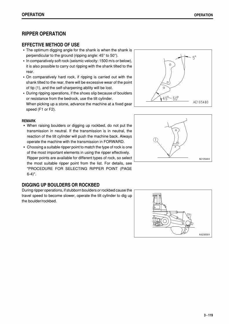
.
OPERATION OPERATION
RIPPER OPERATION
EFFECTIVE METHOD OF USEThe optimum digging angle for the shank is when the shank isperpendicular to the ground (ripping angle: 45° to 50°).In comparatively soft rock (seismic velocity: 1500 m/s or below),it is also possible to carry out ripping with the shank tilted to therear.On comparatively hard rock, if ripping is carried out with theshank tilted to the rear, there will be excessive wear of the pointof tip (1), and the self-sharpening ability will be lost.During ripping operations, if the shoes slip because of bouldersor resistance from the bedrock, use the tilt cylinder.When picking up a stone, advance the machine at a fixed gearspeed (F1 or F2).
REMARKWhen raising boulders or digging up rockbed, do not put thetransmission in neutral. If the transmission is in neutral, thereaction of the tilt cylinder will push the machine back. Alwaysoperate the machine with the transmission in FORWARD.Choosing a suitable ripper point to match the type of rock is oneof the most important elements in using the ripper effectively.Ripper points are available for different types of rock, so selectthe most suitable ripper point from the list. For details, see"PROCEDURE FOR SELECTING RIPPER POINT (PAGE6-4)".
DIGGING UP BOULDERS OR ROCKBEDDuring ripper operations, if stubborn boulders or rockbed cause thetravel speed to become slower, operate the tilt cylinder to dig upthe boulder/rockbed.
3 - 119

.
OPERATIONOPERATION
OPERATING ON SLOPESWhen using the variable ripper, adjust the length of the tilt cylinderto select dimension L.
METHOD OF OPERATING PIN PULLER 1. Stop the machine in a safe place and lower the shank to the
ground. 2. Operate the pin puller controller switch to the PULL OUT
position and remove the mounting pin. 3. Move the ripper up or down to set to the desired shank position.
3 - 120

.
OPERATION OPERATIONOPERATION OPERATION
4. Operate the pin puller control switch to insert the mounting pin.If the pin does not match the position of the hole in the shank,set the pin puller control switch to the PUSH IN position andslowly move the ripper up or down.
REMARKWhen raising the pin position to increase the digging depth, use along protector to prevent wear of the shank.
3 - 121

.
OPERATIONOPERATION
OPERATING METHOD FOR RIPPING OPERATIONS
BASIC OPERATING METHOD
TRACK OF RIPPER SHANKCarry out the ripping operation as follows, passing through the points shown in the diagram above.(1) Tilt the ripper back, lower the ripper point to the ground that the place to begin ripping, and raise the rear of the
machine. (2) To press the decelerator pedal and lower the engine speed, set the speed range to F1, and tilt the ripper to insert
the point to the specified depth.(3) When the ripper point reaches the specified depth, raise the engine speed to full speed and travel forward.
Tilt the shank and carry out ripping.If the circuit is relieved even when the shank is tilted, change the shank mounting hole to the hole below andreduce the ripping depth.
(4) After completing the ripping, travel forward, raise the shank from the bed rock, then travel in reverse.(5) While traveling in reverse, tilt the ripper back, and when the starting point for the ripping is reached, lower the
ripper.
REMARKIf the ripper is applied with the rear of the machine raised fromthe ground, the drawbar pull will be low, so the ripping efficiencywill be reduced.If the ripping depth is kept constant, there will be nounevenness, and this will increase the efficiency of the dozingoperation.
3 - 122

.
OPERATION OPERATION
RIPPING BY CLIFFSWhen carrying out ripping at the edge of a cliff, tilt the ripper backto make depth (L) longer.Depress the decelerator pedal, drive slowly forward, and whenthe ripper point contacts the cliff, tilt the ripper.
RIPPING BY SLOPE FACES(Giant ripper)
When carrying out ripping work at the edge of slope faces, makethe ripper tilt back angle small, and if there is an area where theslope face has not been ripped, apply the ripper diagonally.
REMARKIn the case of the multi-shank ripper, carry out ripping at rightangles to the slope face.
Cross rippingOn jobsites with hard bedrock, for rocks and boulders which areimpossible to break or dig up with one ripping pass, carry out thesecond ripping pass at right angles to the first ripping direction.At the edge of cliffs, where it is impossible to apply the ripper ina cross direction, make the space between the shanks smallerand carry out ripping.
During the ripping operation, if there is any hard bedrock, carryout ripping in the opposite direction to the direction where theripper was applied. If it is still impossible to break up the rock,break up the area around the bedrock a little at the time.When carrying out concentrated ripping of hard bedrock, thework efficiency is high if the ripper is applied to the whole of thedigging face.
3 - 123

.
OPERATIONOPERATION
DIGGING UP BOULDERSDuring the ripping operation, if boulders are found which are difficult to break and shoe slippage occurs, dig up theboulder as follows. 1. Depress the decelerator pedal and lower the engine speed to
a point where there is no shoe slippage.
2. Operate the ripper lever to the TILT position and carry outripping and digging.
3. If there are boulders which are impossible to break or dig upwith the tilt operation, move forward slightly and tilt the shankback, then operate the tilt again and dig up the boulder.
4. Even when the operation in Step 3 is repeated, if it isimpossible to break or dig up the boulder, drive back about 10cm, raise the shank, avoid the rock or boulder that cannot beripped, then drive forward and start ripping again.
3 - 124

.
OPERATION OPERATION
PRECAUTIONS WHEN RIPPINGFor the digging angle when ripping, set so that the top of theshank is perpendicular, then lower the ripper.Do not carry out ripping for long periods with the shank tiltedback. The tip of the point will wear to a round shape.
Do not change the direction of travel during the rippingoperation. This will cause breakage of the shank. Whenchanging the direction of travel, remove the shanks from theground before turning.
Never drive in reverse when the ripper point is inserted in thebedrock. The pin installing the point will break and the point willfall off.Stop the machine, tilt back slightly, then raise the ripper slowly.
After ripping, if the broken rock is comparatively large, avoidtraveling over the ripping path when traveling in reverse. Whentraveling in reverse, check the rear carefully to avoid heating anylarge rocks. As far as possible, choose level ground to travelover.
3 - 125

.
OPERATIONOPERATION
ADJUSTING POSTURE OF WORK EQUIPMENT
WARNINGWhen adjusting, it is dangerous if the work equipment is moved by mistake. Set the work equipment in a safe condition, then stopthe engine and lock the work equipment securely with the work equipment lock lever.
BLADE ADJUSTMENT
TILTING THE TILTDOZER
NOTICEThe maximum amount of tilt is 1065 mm (3.6 ft).(When the semi-U blade is used.)Be sure not to exceed 1065 mm (3.6 ft) for the tilt.Tilt exceeding the maximum limit imposes unnecessary forces onto sections. This may cause damage to the machine.
According to the operation of the blade control lever, the followingtilt amount can be obtained:Right side: 650 mm (25.6 in) or moreLeft side: 650 mm (25.6 in) or moreIf more tilt is required, do as follows.Use bar handle (2) installed to the left brace to turn brace (1) andchange the length (A) of the brace. This makes it possible to obtaina maximum tilt of 1065 mm (42.0 in).
Standard distance between joints A: 1552 mm (61.1 in)
ADJUSTING SHIM IN BLADE CYLINDER CAPSet the standard shim adjustment in the blade cylinder cap to 4 mm(0.16 in).Remove shims to balance the wear of the cap and the ball at theend of the piston rod.The proper clearance to be maintained with the shims is 0.2 to 0.5mm (0.008 to 0.02 in).
3 - 126

.
OPERATION OPERATION
ADJUSTING BRACE
WARNINGIf maintenance is carried out with the engine running, always have oneworker sitting in the operator's seat while another worker carries out themaintenance. Both workers must mutually confirm the safety during theoperation.
Start the engine and use inching control to tilt to the left and right.Adjustment can be carried out easily by rotating the brace handlewhile raising and lowering.
When extending the braceIt is easy to carry out the adjustment if the blade is set on top of ablock and the brace handle is turned.
REMARKWhen operated in this way, the blade is tilted, so the handlegradually becomes heavier. When this happens, return the bladefrom the tilt position to the horizontal position and turn the handleagain according to the procedure given above.
SHIM ADJUSTMENTAdjust the thickness of shim so that the ball joint play (7 points) inthe axial direction (shown by the arrow) does not exceed 1 mm(0.04 in).
1. Remove shim (1) and tighten bolts (2) to eliminate the ball jointplay.
2. Measure clearance "A" and remove bolts (2). 3. Install shim (1) having its thickness of "A" mm to "A + 1" mm
("A" in. to "A + 0.04" in) in place with bolts 2. 4. Confirm that ball joint can move smoothly after tightening bolts.
3 - 127

.
OPERATIONOPERATION
ADJUSTING RIPPER
ADJUSTING DIGGING DEPTHMounting pin holes are provided in the shank and these are used according to the desired digging depth. For normaluse, use the bottom hole, and when particularly deep digging is needed, use the top hole.For the method of changing the depth of digging,see "METHOD OF OPERATING PIN PULLER (PAGE 3-120)". 1. Place a pointed object on the tip of pin (1), then hit with a
hammer to remove from the opposite side. 2. Remove pin (2) and change the position of the shank hole. 3. Insert pin (1) partially by hand then knock it in with a hammer.
The pin is made of one piece, so insert it partially by handthen knock it in with a hammer.When a giant ripper is installed, use the pin puller.For details, see "METHOD OF OPERATING PIN PULLER(PAGE 3-120)".
REPLACING POINT AND PROTECTORTo protect the shank, if the protector and point installed to the tipare worn, replace them.Place a pin remover on the pin marked by the arrow, then hit witha hammer to remove from the opposite side.
REMARKThe pin is a unitized type, so insert the pin partially by hand, thenknock it in fully with a hammer.
3 - 128
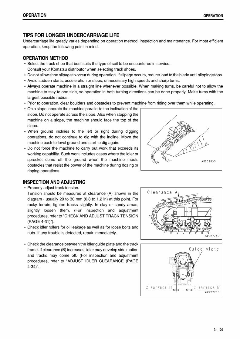
.
OPERATION OPERATION
TIPS FOR LONGER UNDERCARRIAGE LIFEUndercarriage life greatly varies depending on operation method, inspection and maintenance. For most efficientoperation, keep the following point in mind.
OPERATION METHODSelect the track shoe that best suits the type of soil to be encountered in service.Consult your Komatsu distributor when selecting track shoes.Do not allow shoe slipage to occur during operation. If slipage occurs, reduce load to the blade until slipping stops.Avoid sudden starts, acceleration or stops, unnecessary high speeds and sharp turns.Always operate machine in a straight line whenever possible. When making turns, be careful not to allow themachine to stay to one side, so operation in both turning directions can be done properly. Make turns with thelargest possible radius.Prior to operation, clear boulders and obstacles to prevent machine from riding over them while operating.On a slope, operate the machine parallel to the inclination of theslope. Do not operate across the slope. Also when stopping themachine on a slope, the machine should face the top of theslope.When ground inclines to the left or right during diggingoperations, do not continue to dig with the incline. Move themachine back to level ground and start to dig again.Do not force the machine to carry out work that exceeds itsworking capability. Such work includes cases where the idler orsprocket come off the ground when the machine meetsobstacles that resist the power of the machine during dozing orripping operations.
INSPECTION AND ADJUSTINGProperly adjust track tension.Tension should be measured at clearance (A) shown in thediagram - usually 20 to 30 mm (0.8 to 1.2 in) at this point. Forrocky terrain, tighten tracks slightly. In clay or sandy areas,slightly loosen them. (For inspection and adjustmentprocedures, refer to "CHECK AND ADJUST TRACK TENSION(PAGE 4-31)").Check idler rollers for oil leakage as well as for loose bolts andnuts. If any trouble is detected, repair immediately.
Check the clearance between the idler guide plate and the trackframe. If clearance (B) increases, idler may develop side motionand tracks may come off. (For inspection and adjustmentprocedures, refer to "ADJUST IDLER CLEARANCE (PAGE4-34)".
3 - 129
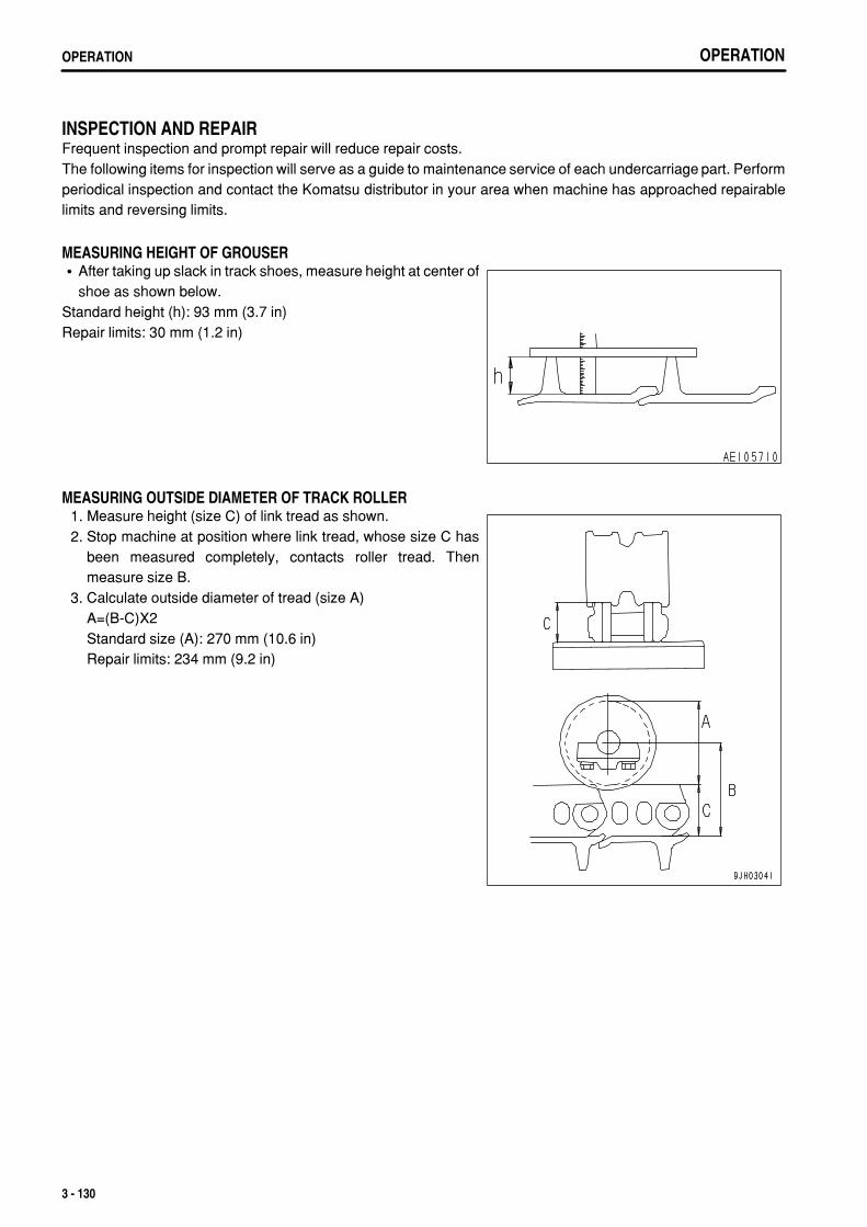
.
OPERATIONOPERATION
INSPECTION AND REPAIRFrequent inspection and prompt repair will reduce repair costs.The following items for inspection will serve as a guide to maintenance service of each undercarriage part. Performperiodical inspection and contact the Komatsu distributor in your area when machine has approached repairablelimits and reversing limits.
MEASURING HEIGHT OF GROUSERAfter taking up slack in track shoes, measure height at center ofshoe as shown below.
Standard height (h): 93 mm (3.7 in)Repair limits: 30 mm (1.2 in)
MEASURING OUTSIDE DIAMETER OF TRACK ROLLER 1. Measure height (size C) of link tread as shown. 2. Stop machine at position where link tread, whose size C has
been measured completely, contacts roller tread. Thenmeasure size B.
3. Calculate outside diameter of tread (size A)A=(B-C)X2Standard size (A): 270 mm (10.6 in)Repair limits: 234 mm (9.2 in)
3 - 130

.
OPERATION TRANSPORTATION
TRANSPORTATIONWhen transporting the machine, observe all related laws andregulations, and be careful to assure safety.
TRANSPORTATION PROCEDUREA trailer should be used for transporting the machine.
3 - 131

.
OPERATIONTRANSPORTATION
LOADING, UNLOADING WORK
WARNINGMake sure the ramp has sufficient width, length and thickness to enable the machine to be safely loaded and unloaded.If the ramp sags appreciably, reinforce it with blocks, etc.When loading and unloading the machine, park the trailer on a flat firm roadbed. Keep a fairly long distance between the roadshoulder and the machine.Remove the mud from the undercarriage to prevent the machine from slipping to the side on slopes.Be sure the ramp surface is clean and free of grease, oil, ice and loose materials.Never change the direction of travel when on the ramps. If it is necessary to change direction, drive off the ramps and correctthe direction, then drive on to the ramps again.
When loading or unloading, always use ramps or a platform and carry out the operations as follows. 1. Properly apply the brakes on the trailer and insert blocks
beneath the tires to ensure that it does not move. Then attachthe ramps in line with the centers of the trailer and the machine.
2. Set the machine in line with the ramps, then load or unload themachine at slow travel.
3. Load the machine correctly in the specified position on thetrailer.
PRECAUTIONS FOR LOADINGAfter placing the machine on the specified position of the trailer, secure it according to the following procedure. 1. Lower the work equipment slowly. 2. Secure control levers with the work equipment lock lever. 3. Set the parking brake lever to the LOCK position. 4. Turn the starting switch to the OFF position stopping the engine, then remove the key. 5. Lock the cab door, left and right engine side covers, and the battery inspection cover. 6. Place blocks under both ends of the tracks to prevent the machine from moving during transportation, and
secure the machine with chains or wire rope of suitable strength.Be particulary careful to secure the machine in position so it does not slip to the side.
3 - 132

.
OPERATION TRANSPORTATION
METHOD OF LIFTING MACHINE
WARNINGNever perform lifting operations with any person on the machine.Always make sure that the wire rope (cable) used for lifting the machine is of ample strength for the weight of the machine.Never try to lift the machine in any posture other than the posture given in the procedure below.There is danger that the machine may lose its balance.When lifting the machine,pay careful attention to the center of gravity to maintain the balance.
When lifting the machine, perform the operation on flat ground asfollows: 1. Stop the engine and be sure to set the parking lever to the
LOCK position. 2. Set the lifting position for the machine as shown in the diagram
on the right.
NOTICEThe lifting procedure applies to machines with standard specifications.The method of lifting differs according to the attachments and optionsactually installed. In such cases, please contact your Komatsu distributorfor information.
For weight, see "SPECIFICATIONS (PAGE 5-2)".
3 - 133

.
OPERATIONTRANSPORTATION
PRECAUTIONS FOR TRANSPORTATION
WARNINGDetermine the route for transporting the machine by taking into accountthe width, height and weight of the machine.
Obey all state and local laws governing the weight, width andlength of a load. Observe all regulations governing wide loads.
TRAVELING ON ROADSWhen traveling on paved roads, use flat shoes to protect their surface.Even when travelling a short distance, always place boards to protect the road surface.
REMARKNote that the asphalt road becomes soft in summer.
REMOVAL OF CAB(Machine equipped with cab) (If equipped)If it is necessary to remove the cab for transportation, disconnectthe washer hoses, cab wiring, and washer motor wiring beforeremoving the cab. 1. Pull the grommet portion in towards the cab from the hole in the
machine cover, then remove. 2. Disconnect 4 washer hoses and the wiring (single wires x 2,
4-pin plug x 1).After removing, cover the washer hoses with a vinyl bag toprevent any dirt or dust from entering.Before removing the cab, measure the clearance betweenthe cab and each lever (joystick and blade control lever,etc.). Note the measurements to use as a standard wheninstalling the cab again.
3 - 134

.
OPERATION TRANSPORTATION
INSTALLATION OF CAB(Machine equipped with cab) (If equipped)Install the cab parts in the opposite order to removal.Connect all parts that were disconnected.Install the cab mounting bolts as follows. 1. Lower the cab slowly on top of the floor frame. 2. Align the cab with the floor frame, then install bolts and
washers in holes (A) - (U).Do not screw the bolts in fully. Screw them in 3 or 4 turns.
3. Tighten the bolts in holes (N) - (U) fully.Tighten in the order (N), (U), (Q), (R), (O), (T), (P), (S).
4. Tighten the bolts, (A) to (M), completely.
If there are any unclear points about removing or installing thecab, please contact your Komatsu distributor.
3 - 135

.
OPERATIONCOLD WEATHER OPERATION
COLD WEATHER OPERATION
PRECAUTIONS FOR LOW TEMPERATUREIf the temperature becomes low, it becomes difficult to start the engine, and the coolant may freeze, so do as follows.
FUEL AND LUBRICANTSChange to oil with low viscosity for all components. For details of the specified visicosity, see "RECOMMENDEDFUEL, COOLANT, AND LUBRICANT (PAGE 4-11)".
COOLANT
WARNINGAntifreeze is toxic. Be careful not to get it into your eyes or on your skin. If it should get into your eyes or on your skin, washit off with large amounts of fresh water and see a doctor at once.When changing the coolant or when handling coolant containing antifreeze that has been drained when repairing the radiator,please contact your Komatsu distributor or request a specialist company to carry out the operation. Antifreeze is toxic. Do notlet it flow into drainage ditches or spray it onto the ground surface.Antifreeze is flammable. Do not bring any flame close. Do not smoke when handling antifreeze.
NOTICEUse Komatsu Supercoolant (AF-NAC) wherever available, or use permanent type antifreeze coolant.Never use methanol, ethanol, or propanol-based antifreeze.Do not use any water leakage prevention agent, either alone, or in combination with antifreeze.Do not mix one brand of antifreeze with a different brand.When using Komatsu super coolant (AF-NAC), there is no need to use a corrosion resistor. For details, see "CLEAN INSIDEOF COOLING SYSTEM (PAGE 4-20)".
For details of the antifreeze mixture when changing the coolant, see "CLEAN INSIDE OF COOLING SYSTEM(PAGE 4-20)".
3 - 136

.
OPERATION COLD WEATHER OPERATION
BATTERY
WARNINGThe battery generates flammable gas. Do not bring fire or sparks near the battery.Battery electrolyte is dangerous. If it gets in your eyes or on your skin, wash it off with a large amount of water and consult adoctor.Battery electrolyte dissolves paint. If it gets on the bodywork, wash it off immediately with water.If the battery electrolyte is frozen, do not charge the battery or start the engine with a different power source. There is dangerthat the battery may explode.Battery electrolyte is toxic. Do not let it flow into drainage ditches or spray it on to the ground surface.
When the ambient temperature drops, the capacity of the battery will also drop. If the battery charge ratio is low, thebattery electrolyte may freeze. Maintain the battery charge as close as possible to 100%. Insulate it against coldtemperature to ensure the machine can be started easily the next morning.
REMARKMeasure the specific gravity and calculate the charging rate from the following conversion table.
ElectrolyteTemperature
ChargingRate (%)
20°C(68°F)
0°C(32°F)
-10°C(14°F)
-20°C(-4°F)
100 1.28 1.29 1.30 1.31
90 1.26 1.27 1.28 1.29
80 1.24 1.25 1.26 1.27
75 1.23 1.24 1.25 1.26
As the battery capacity drastically drops in low temperatures, cover or remove the battery from the machine, storethe battery in a warm place, and install it again the next morning.If the electrolyte level is low, add distilled water in the morning before beginning work. Do not add water after theday's work to prevent diluted electrolyte in the battery from freezing during the night.
AFTER COMPLETION OF WORK
WARNINGPerforming idle-running of the tracks is dangerous, stay well away from the tracks.
To prevent mud, water, or the undercarriage from freezing and making it impossible for the machine to move on thefollowing morning, observe the following precautions.
Remove all the mud and water from the machine body. In particular, wipe the hydraulic cylinder rods clean toprevent damage to the seal caused by mud, dirt, or drops of water on the rod from getting inside the seal.Park the machine on hard, dry ground.If this is impossible, park the machine on boards.The boards prevent the tracks from freezing to the ground, and allow the machine to be moved the next morning.Open the drain valve and drain any water collected in the fuel system to prevent it from freezing.Fill the fuel tank to capacity. This minimizes moisture condensation in the tank when the temperature drops.
3 - 137

.
OPERATIONCOLD WEATHER OPERATION
After operation in water or mud, remove water from undercarriage as described below to extend undercarriageservice life.
3 - 138

.
OPERATION COLD WEATHER OPERATION
AFTER COLD WEATHERWhen the season changes and the weather becomes warmer, do as follows.
Replace the fuel and oil for all parts with oil of the viscosity specified.For details, see "RECOMMENDED FUEL, COOLANT, AND LUBRICANT (PAGE 4-11)".If for any reason permanent antifreeze cannot be used, and an ethylene glycol base antifreeze (winter, oneseason type) is used instead, or if no antifreeze is used, drain the cooling system completely. Thoroughly flushout the cooling system and fill it with fresh coolant.
3 - 139

.
OPERATIONLONG-TERM STORAGE
LONG-TERM STORAGE
BEFORE STORAGEWhen putting the machine in storage for a long time (more than one month), do as follows.
Clean and wash all parts, then store the machine indoors. If the machine has to be stored outdoors, select levelground and cover the machine with canvas.Completely fill the fuel tank. This prevents moisture from collecting.Lubricate and change the oil before storage.Coat the exposed portion of the hydraulic cylinder piston rod with grease.Disconnect the negative terminals of the battery and cover it, or remove it from the machine and store itseparately.Place all control levers at the neutral position, set the work equipment lock lever and parking brake lever to thelockposition, and set the fuel control dial to the low idling position.
DURING STORAGE
WARNINGIf it is necessary to perform the rust-prevention operation while the machine is indoors, open the doors and windows to improveventilation and prevent gas poisoning.
During storage, operate and move the machine for a short distance once a month so that a new film of oil will coatmoving parts. At the same time, also charge the battery.When operating the work equipment, wipe off all the grease from the hydraulic cylinder rods.If the machine is equipped with an air conditioner, operate the air conditioner for 3 to 5 minutes once a month tolubricate all parts of the air conditioner compressor. Always run the engine at low idle when doing this. In addition,check the refrigerant level twice a year.
AFTER STORAGENOTICEIf the machine has been stored without carrying out the monthly rust-prevention operation, consult your Komatsu distributorbefore using it.
When using the machine after long-term storage, do as follows before using it.Wipe off the grease from the hydraulic cylinder rods.Add oil and grease at all lubrication points.When the machine is stored for a long period, moisture in the air will mix with the oil. Check the oil before and afterstarting the engine. If there is water in the oil, change all the oil.
STARTING MACHINE AFTER LONG-TERM STORAGEWhen starting the engine after the machine has been in storage for a long period, carry out the warming-up operationthoroughly. For details, see the procedure in "WARMING UP OPERATIONS (PAGE 3-91)".
3 - 140

.
OPERATION TROUBLESHOOTING
TROUBLESHOOTING
AFTER RUNNING OUT OF FUELWhen starting after running out of fuel, will with fuel and bleed the air from the fuel system before starting.For details of bleeding the air, see "REPLACE FUEL FILTER CARTRIDGE (PAGE 4-59)".
METHOD OF TOWING MACHINE
WARNINGBe sure to use a wire rope sufficiently strong for the towing weight.When using the towing hook, be sure to use a shackle.Set the wire rope level and align it with the track frame.Tow the machine slowly.
If the machine sinks in mud and cannot get out under its ownpower, or if being used to tow a heavy object, fit the wire to thetowing hook as shown in the diagram on the right, or in the case ofmachines with a drawbar, fit the wire to the drawbar pin whentowing.
NOTICEPermissible load for towing hook: 48500 kg (475623 N)Always carry out towing operations within the specified range for thepermissible load.
3 - 141
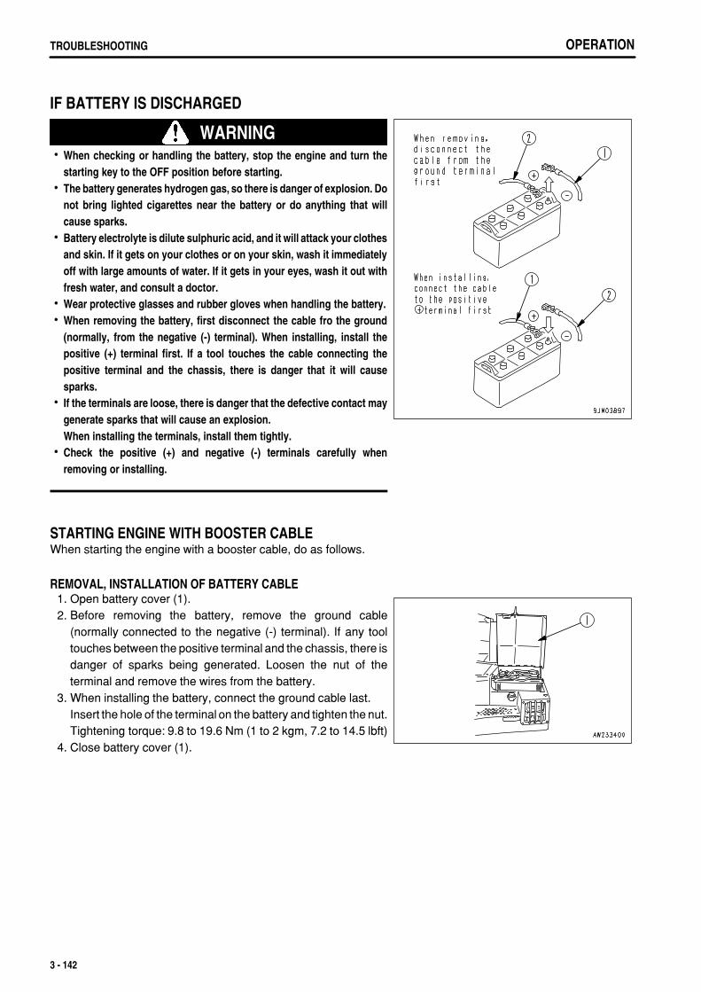
.
OPERATIONTROUBLESHOOTING
IF BATTERY IS DISCHARGED
WARNINGWhen checking or handling the battery, stop the engine and turn thestarting key to the OFF position before starting.The battery generates hydrogen gas, so there is danger of explosion. Donot bring lighted cigarettes near the battery or do anything that willcause sparks.Battery electrolyte is dilute sulphuric acid, and it will attack your clothesand skin. If it gets on your clothes or on your skin, wash it immediatelyoff with large amounts of water. If it gets in your eyes, wash it out withfresh water, and consult a doctor.Wear protective glasses and rubber gloves when handling the battery.When removing the battery, first disconnect the cable fro the ground(normally, from the negative (-) terminal). When installing, install thepositive (+) terminal first. If a tool touches the cable connecting thepositive terminal and the chassis, there is danger that it will causesparks.If the terminals are loose, there is danger that the defective contact maygenerate sparks that will cause an explosion.When installing the terminals, install them tightly.Check the positive (+) and negative (-) terminals carefully whenremoving or installing.
STARTING ENGINE WITH BOOSTER CABLEWhen starting the engine with a booster cable, do as follows.
REMOVAL, INSTALLATION OF BATTERY CABLE 1. Open battery cover (1). 2. Before removing the battery, remove the ground cable
(normally connected to the negative (-) terminal). If any tooltouches between the positive terminal and the chassis, there isdanger of sparks being generated. Loosen the nut of theterminal and remove the wires from the battery.
3. When installing the battery, connect the ground cable last.Insert the hole of the terminal on the battery and tighten the nut.Tightening torque: 9.8 to 19.6 Nm (1 to 2 kgm, 7.2 to 14.5 lbft)
4. Close battery cover (1).
3 - 142

.
OPERATION TROUBLESHOOTING
PRECAUTIONS WHEN CONNECTING AND DISCONNECTING BOOSTER CABLE
WARNINGWhen connecting the cables, never contact the positive (+) and negative(-) terminals.When starting the engine with a booster cable, wear safety glasses andrubber gloves.Be careful not to let the normal machine and problem machine contacteach other. This prevents sparks from generating near the battery whichcould ignite the hydrogen gas given off by the battery.Make sure that there is no mistake in the booster cable connections.The final connection is to the engine block of the problem machine, butsparks will be generated when this is done, so connect to a place as faras possible from the battery.When disconnecting the booster cable, take care not to bring the clipsin contact with each other or with the machine body.
NOTICEThe size of the booster cable and clip should be suitable for the battery size.The battery of the normal machine must be the same capacity as that of the engine to be started.Check the cables and clips for damage or corrosion.Make sure that the cables and clips are firmly connected.Check that the work equipment lock levers and parking brake levers of both machines are in the LOCK position.Check that each lever is in the NEUTRAL position.
CONNECTING THE BOOSTER CABLESKeep the starting switch of the normal machine and problem machine both at the OFF position.Connect the booster cable as follows, in the order of the numbers marked in the diagram. 1. Make sure that the starting switches of the normal machine
and problem machine are both at the OFF position. 2. Connect one clip (1) of booster cable (A) to the positive (+)
terminal of the problem machine. 3. Connect the other clip (2) of booster cable (A) to the positive (+)
terminal of the normal machine. 4. Connect one clip (3) of booster cable (B) to the negative (-)
terminal of the normal machine. 5. Connect the other clip of booster cable (B) to the engine block
of the problem machine.
STARTING THE ENGINE 1. Make sure the clips are firmly connected to the battery terminals. 2. Start the engine of the normal machine and keep it to run at high idling speed. 3. Turn the starting switch of the problem machine to the START position and start the engine. If the engine doesn't
start at first, try again after 2 minutes or so.
3 - 143

.
OPERATIONTROUBLESHOOTING
DISCONNECTING THE BOOSTER CABLESAfter the engine has started, disconnect the booster cables in the reverse of the order in which they were connected. 1. Remove one clip (1) of booster cable (B) from the engine block
of problem machine. 2. Remove the other clip (2) of booster cable (B) from negative (-)
terminal of the normal machine. 3. Remove one clip (3) of booster cable (A) from the positive (+)
terminal of the normal machine. 4. Remove the other clip (4) of booster cable (A) from positive (+)
terminal of the problem machine.
3 - 144

.
OPERATION TROUBLESHOOTING
OTHER TROUBLE
ELECTRICAL SYSTEM( ): Always contact your Komatsu distributor when dealing with these items.In cases of problems or causes which are not listed below, contact your Komatsu distributor for repairs.
Problem Main cause Remedy
Lamp does not glow brightly evenwhen the engine runs at high speed
Defective wiring ( Check, repair loose terminals, disconnections Check fuses and diodes in fuse box)
Lamp flickers while engine isrunning
Defective adjustment of fan belttension
Adjust fan belt tension For details, see EVERY 250 HOURS SERVICE
Charge lamp does not go out evenwhen engine is running
Defective alternatorDefective wiring
( Replace)( Check, repair
Check fuse, diode in fuse box)Abnormal noise is generated fromalternator
Defective alternator ( Replace)
Starting motor does not crankwhen starting switch is turned ON
Defective wiringInsufficient battery charge
( Check, repair) Charge
Pinion of starting motor keepsgoing in and out
Insufficient battery charge Charge
Starting motor turns enginesluggishly
Insufficient battery chargeDefective starting motor
Charge( Replace)
Starting motor disengages beforeengine starts
Defective wiringInsufficient battery charge
( Check, repair) Charge
Engine pre-heating monitor lampdoes not light up(When the temperature of theengine coolant exceed 20°C(68°F), this condition is normal)
Defective wiringDefective timerDefective monitorDisconnection in glow plug
( Check, repair)( Replace)( Replace)( Replace)
Air conditioner operation isdefective
Blown fuseInsufficient battery chargeDefective air conditioner switchDefective blower switchDefective compressor
( Check, repair) Charge( Replace air conditioner switch)( Replace blower switch)( Replace)
Blade does not pitch when pitchoperation is carried out (dual tiltspecification machine only)
Defective wiringDefective switchDefective solenoid valve
( Check, repair)( Replace)( Replace)
3 - 145
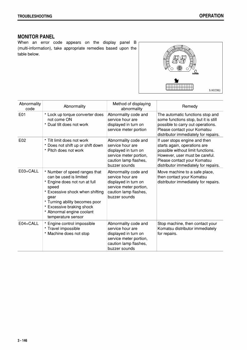
.
OPERATIONTROUBLESHOOTING
MONITOR PANELWhen an error code appears on the display panel B(multi-information), take appropriate remedies based upon thetable below.
Abnormalitycode
AbnormalityMethod of displaying
abnormalityRemedy
E01 Lock up torque converter doesnot come ONDual tilt does not work
Abnormality code andservice hour aredisplayed in turn onservice meter portion
The automatic functions stop andsome functions stop, but it is stillpossible to carry out operations.Please contact your Komatsudistributor immediately for repairs.
E02 Tilt limit does not workDoes not shift up or shift downPitch does not work
Abnormality code andservice hour aredisplayed in turn onservice meter portion,caution lamp flashes,buzzer sounds
If user stops engine and thenstarts again, operations arepossible without limit functions.However, user must be careful.Please contact your Komatsudistributor immediately for repairs.
E03+CALL Number of speed ranges thatcan be used is limitedEngine does not run at fullspeedExcessive shock when shiftinggearTurning ability becomes poorExcessive braking shockAbnormal engine coolanttemperature sensor
Abnormality code andservice hour aredisplayed in turn onservice meter portion,caution lamp flashes,buzzer sounds
Move machine to a safe place,then contact your Komatsudistributor immediately for repairs.
E04+CALL Engine control impossibleTravel impossibleMachine does not stop
Abnormality code andservice hour aredisplayed in turn onservice meter portion,caution lamp flashes,buzzer sounds
Stop machine, then contact yourKomatsu distributor immediatelyfor repairs.
3 - 146

.
OPERATION TROUBLESHOOTING
CHASSIS( ): Always contact your Komatsu distributor when dealing with these items.In cases of problems or causes which are not listed below, contact your Komatsu distributor for repairs.
Problem Main causes Remedy
Oil pressure in torqueconverter fails to rise
Improper tightening of oil pipe,pipe joint, air leaking in or oilleaking out because of damageWear, scuffing of gear pumpInsufficient oil in transmissioncase
Clogged oil filter element strainerin transmission case
Check, repair
( Check, replace) Add oil to the specified level. For
details, see CHECK BEFORESTARTING
Clean. For details, see EVERY1000 HOURS SERVICE
Torque converter is overheats Clogged radiatorLoose fan belt Engine water temperature is high Clogged oil cooler Oil pressure too low
Lack of flow of lubricant causedby wear of power train gear pump
Replace fan belt See Engine related parts( Clean or replace) Go to "Oil pressure in torque
converter fails to rise"( Replace gear pump)
Torque converter oiltemperature gauge does notwork
Defective oil temperature gaugeDefective contact in wiringconnection
( Replace oil temperature gauge)( Check, repair)
Lacks drawbar pull (machinedoes not pick up speed)
Lack of engine horsepower Oil pressure in torque converter istoo lowSteering clutch is slipping
See Engine related parts Go to "Oil pressure in torque
converter fails to rise"( Check, repair)
Machine will not move offwhen joystick is placed atFORWARD or REVERSE
Lack of oil in steering clutch case
Transmission oil pressure doesnot rise Steering clutch slips
Wear, scuffing of gear pump Clogged oil strainer element in
steering clutch case Defective joystick Parking brake lever is at LOCK
position
Add oil to the specified level. For details, see CHECK BEFORE
Go to "oil pressure in torqueconverter fails to rise"
( Check, repair) Clean. For details, see EVERY
1000 HOURS SERVICE
Set to FREE position
Does not steer even whensteering is operated
Brake is not applied on side whichis pulledDefective joystick
( Adjust linkage,Check brake pressure)
( Check, wiring)Machine doesn't stop whenbrake pedal are depressed
Defective brake adjustment
Defective Brake pedal
( Adjust linkage,Check brake pressure)
( Check, wiring)Track comes off Track is too loose Adjust track tension. For details,
see WHEN REQUIRED.Sprocket develops abnormalwear
Track is too loose or too tight Adjust track tension. For details,see WHEN REQUIRED.
3 - 147

.
OPERATIONTROUBLESHOOTING
Problem Main causes Remedy
Brake rises too slowly or doesnot rise at all(or blade tilts too slowly)
Lack of hydraulic oil
Defective hydraulic switchWork equipment lock lever is atLOCK position
Add oil to specified level. Fordetails, see EVERY 250 HOURSSERVICE
Replace Set to FREE position
Ripper moves too slowly Lack of hydraulic oil position
Defective solenoid valveWork equipment lock lever is atLOCK position
Add oil to specified level. Fordetails, see EVERY 250 HOURSSERVICE
Replace Set to FREE position
Insufficient force of ripper Leakage from piping ( Tighten)
3 - 148

.
OPERATION TROUBLESHOOTING
ENGINE( ): Always contact your Komatsu distributor when dealing with these items.In cases of problems or causes which are not listed below, contact your Komatsu distributor for repairs.
Problem Main causes Remedy
Engine oil pressure monitorflashes when engine speed israised after completion ofwarm-up
Engine oil pan oil level is low(sucking in air)Clogged oil filter cartridge
Defective tightening of oil pipejoint, oil leakage from damagedpartDefective monitor panel
Add oil to specified level, seeCHECK BEFORE STARTING
Replace cartridge, see EVERY 500HOURS SERVICE
( Check, repair)
( Replace)
Steam is emitted from top partof radiator (pressure valve)
Cooling water level low, waterleakageLoose fan belt Dirt or scale accumulated incooling system
Add cooling water, repair, seeCHECK BEFORE STARTING
Replace fan belt Change cooling water, clean inside
of cooling system, see WHENREQUIRED
Engine water temperaturemonitor remains alight altitudeoperation)
Clogged radiator fin or damaged finDefective thermostat Loose radiator filler cap (highaltitude operation)Defective monitor panel
Clean or repair, see WHENREQUIRED
( Replace thermostat) Tighten cap or replace packing
( Replace)
Engine does not start whenstarting motor is turned
Lack of fuel
Air in fuel system No fuel in fuel filterStarting motor cranks enginesluggishlyDefective valve clearance
Add fuel, see CHECK BEFORESTARTING
Repair place where air is sucked in( Replace pump or nozzle) See ELECTRICAL SYSTEM
( Adjust valve clearance)
Exhaust gas is white or blue Too much oil in oil pan
Improper fuel
Add oil to specified level, seeCHECK BEFORE STARTING
Change to specified fuel
Exhaust gas occasionally turnsblack
Clogged air cleaner element
Defective nozzle Defective compressionDefective turbocharger
Clean or replace, see WHENREQUIRED
( Replace nozzle)( Adjust valve clearance)( Clean or replace, turbocharger)
Combustion noise occasionallymakes breathing sound
Defective compression ( Replace nozzle)
Abnormal noise generated(combustion or mechanical)
Low grade fuel being used Overheating
Damage inside muffler Excessive valve clearance
Change to specified fuel See item "Indicator of water
temperature gauge is in red range onright side of gauge".
( Replace muffler)( Adjust valve clearance)
3 - 149

.
OPERATIONTROUBLESHOOTING
WHEN MODE SELECTION SYSTEM FLASHESIf the caution lamp flashes, or it becomes impossible to control the engine speed with the fuel control dial ordecelerator pedal, stop operation immediately, check the monitor panel display, then contact your Komatsudistributor for repairs.In addition to the above problems, if any of the problems in the table below occur, there is probably an abnormalityin the work equipment lever switch, transmission speed range sensor, or other part, so please contact your Komatsudistributor for repairs.
Mode Operation Abnormality
Economy DozingEngine speed varies, difficult to carry out operationNo sense of control, engine stays at full or partial
Slow reverse ReverseRipper RAISE speed is slowSlow reverse speed is slow
Lock-up All operationsLock-up does not workGearshifting shock becomes excessive
-Traveling under
own powerEngine speed becomes partial when traveling under ownpower
3 - 150

.
4 - 1

.
MAINTENANCEGUIDES TO MAINTENANCE
GUIDES TO MAINTENANCEDo not carry out any inspection and maintenance operation that is not found in this manual.Stop the machine on flat hard ground when carrying out inspection and maintenance.
CHECK SERVICE METER:Check the service meter reading every day to see if the time has come for any necessary maintenance to be carriedout.
KOMATSU GENUINE REPLACEMENT PARTS:Use Komatsu genuine parts specified in the Parts Book as replacement parts.
KOMATSU GENUINE OILS:For lubrication of the machine, use the Komatsu genuine lubricants. Moreover use oil of the specified viscosityaccording to the ambient temperature.
ALWAYS USE CLEAN WASHER FLUID:Use automobile window washer fluid, and be careful not to let any dirt get into it.
CLEAN OIL AND GREASE:Use clean oil and grease. Also, keep the containers of the oil and grease clean. Keep foreign materials away fromoil and grease.
CHECK FOREIGN MATERIAL IN DRAINED OIL:After oil is changed or filters are replaced, check the old oil and filters for metal particles and foreign materials. If largequantity of metal particles or foreign materials are found, always report to the person in charge, and carry outsuitable action.
FUEL STRAINER:If your machine is equipped with a fuel strainer, do not remove it while fueling.
WELDING INSTRUCTIONS:Cut off power. Wait for approx. one minute after turning off the engine starting switch key, and then disconnectthe negative (-) terminal of the battery.Do not apply more than 200 V continuously.Connect grounding cable within 1 m (3.3 ft) from the area to be welded. If grounding cable is connected nearinstruments, connectors, etc., the instruments may have troubles.Avoid seals or bearings from being between the area to be welded and the position of grounding point.Do not use the area around the work equipment pins or the hydraulic cylinders as the grounding point.
OBJECTS IN YOUR POCKETS:When opening inspection windows or the oil filler port of the tank to carry out inspection, be careful not to dropnuts, bolts, or tools inside the machine.If such things are dropped inside the machine, it will cause damage and malfunction of the machine, and will leadto failure. If you drop anything inside the machine, always remove it immediately.Do not put unnecessary things in your pockets. Carry only things which are necessary for inspection.
4 - 2

.
MAINTENANCE GUIDES TO MAINTENANCE
DUSTY WORKSITES:When working at dusty worksites, do as follows:
Inspect the air cleaner clogging monitor frequently to see if the air cleaner is clogged.Clean the radiator core frequently to avoid clogging.Clean and replace the fuel filter frequently.Clean electrical components, especially the starting motor and alternator, to avoid accumulation of dust.When inspecting or changing the oil, move the machine to a place that is free of dust to prevent dirt from gettinginto the oil.
AVOID MIXING OILS:Never mix different kinds of oil. If a different type of oil has to be added, drain the old oil and replace all the oil withthe new type of oil.
LOCKING INSPECTION COVERS:Lock inspection cover in position securely with a lock bar. If inspection or maintenance is carried out with theinspection cover open and not locked in position, there is a hazard that it may be suddenly blown shut by the windand cause injury to the worker.
BLEEDING AIR:After changing the oil, or replacing or cleaning the filter element or strainer, bleed the air from inside the circuit.
PRECAUTIONS WHEN INSTALLING HYDRAULIC HOSES:When removing parts at locations where there are O-rings or gasket seals, clean the mounting surface, andreplace with new parts.When doing this, be careful not to forget to assemble the O-rings and gaskets.When installing the hoses, do not twist them or bend them into loops with a small radius.This will cause damage to the hose and markedly reduce its service life.
CHECKS AFTER INSPECTION AND MAINTENANCE:If you forget to carry out the checks after inspection and maintenance, unexpected problems may occur, and thismay lead to serious injury or property damage. Always do as following.
Checks after operation (with engine stopped)Have any inspection and maintenance points been forgotten?Have all inspection and maintenance items been carried out correctly?Have any tools or parts been dropped inside the machine? It is particularly dangerous if parts are droppedinside machine and get caught in the lever linkage mechanism.Is there any leakage of water or oil?Have all the bolts been tightened?
Checks when operating engineFor details of the checks when operating the engine, see "PROPER TOOLS (PAGE 2-29)" and pay carefulattention to safety.Are the inspection and maintenance items working properly?Is there any leakage of oil when the engine speed is raised and load is applied to the oil pressure?
4 - 3

.
MAINTENANCEGUIDES TO MAINTENANCE
PRECAUTIONS WHEN OPENING AND CLOSING ENGINE SIDE COVER:When standing on track to open the engine side cover, adopt astanding position, hold the side cover with both thumbs, andopen it slowly with your other fingers.When the side cover is open, do not open or close the cab.Before opening or closing the cab, always close the engine sidecover first.
4 - 4
.
MAINTENANCE OUTLINES OF SERVICE
OUTLINES OF SERVICEAlways use Komatsu genuine parts for replacement parts, grease or oil.When changing the oil or adding oil, do not mix different types of oil. When changing the type of oil, drain all theold oil and fill completely with the new oil. Always replace the filter at the same time. (There is no problem if thesmall amount of oil remaining in the piping mixes with the new oil.)Unless otherwise specified, when the machine is shipped from the factory, it is filled with the oil and coolant listedin the table below.
Item Type
Engine oil pan Engine oil EO15W40DH (Komatsu genuine parts)
Damper case
Powertrain oil TO30 (Komatsu genuine parts)Power train oil pan
Final drive case
Hydraulic oil system Powertrain oil TO10 (Komatsu genuine parts)
Radiator Supercoolant AF-NAC (density: 30% or above) (Komatsu genuine parts)
HANDLING OIL, FUEL, COOLANT, AND PERFORMING OIL CLINIC
OILOil is used in the engine and hydraulic equipment under extremely severe conditions (high temperature, highpressure), and deteriorates with use.Always use oil that matches the grade and maximum and minimum ambient temperatures recommended in theOperation and Maintenance Manual. Even if the oil is not dirty, always change the oil at the specified interval.Oil corresponds to blood in the human body, always be careful when handling it to prevent any impurities (water,metal particles, dirt, etc.) from getting in.The majority of problems with the machine are caused by the entry of such impurities.Take particular care not to let any impurities get in when storing or adding oil.Never mix oils of different grades or brands.Always add the specified amount of oil.Having too much oil or too little oil are both causes of problems.If the oil in the work equipment is not clear, there is probably water or air getting into the circuit. In such cases,please contact your Komatsu distributor.When changing the oil, always replace the related filters at the same time.We recommend you have an analysis made of the oil periodically to check the condition of the machine. Forthose who wish to use this service, please contact your Komatsu distributor.When using commercially available oil, it may be necessary to reduce the oil change interval.We recommend that you use the Komatsu oil clinic to carry out a detailed checks of the characteristics of the oil.
4 - 5

.
MAINTENANCEOUTLINES OF SERVICE
FUELTo prevent the moisture in the air from condensing and forming water inside the fuel tank, always fill the fuel tankafter completing the day's work.The fuel pump is a precision instrument, and if fuel containing water or dirt is used, it cannot work properly.Be extremely careful not to let impurities get in when storing or adding fuel.Always use the fuel specified for the temperature in the Operation and Maintenance Manual.
If the fuel is used at temperatures lower than the specified temperature (particularly at temperatures below -15°C (5°F), the fuel will solidify.If the fuel is used at temperatures higher than the specified temperature, the viscosity will drop, and this mayresult in problems such as a drop in output.
Before starting the engine, or when 10 minutes have passed after adding fuel, drain the sediment and water fromthe fuel tank.If the engine runs out of fuel, or if the filters have been replaced, it is necessary to bleed the air from the circuit.If there is any foreign material in the fuel tank, wash the tank and fuel system.
NOTICEAlways use diesel oil for the fuel.To ensure good fuel consumption characteristics and exhaust gas characteristics, the engine mounted on this machine uses anelectronically controlled high-pressure fuel injection device. This device requires high precision parts and lubrication, so if lowviscosity fuel with low lubricating ability is used, the durability may drop markedly.
COOLANT AND WATER FOR DILUTIONThe coolant has the important function of preventing corrosion as well as preventing freezing.Even in the areas where freezing is not an issue, the use of antifreeze coolant is essential.Komatsu machines are supplied with Komatsu Supercoolant (AF-NAC). Komatsu Supercoolant (AF-NAC) hasexcellent anticorrosion, antifreeze and cooling properties and can be used continuously for 2 years or 4000 hours.Komatsu Supercoolant (AF-NAC) is strongly recommended wherever available.When using Komatsu super coolant (AF-NAC), there is no need to use a corrosion resistor. For details, see"CLEAN INSIDE OF COOLING SYSTEM (PAGE 4-20)".When diluting the antifreeze coolant, use distilled water or tap water (soft water).Natural water, such as a river water or well water (hard water), contains large amounts of minerals (calcium,magnesium, etc.), and this makes it easier for scale to form inside the engine or radiator. Once scale is depositedinside the engine or radiator, it is extremely difficult to remove. It also causes overheating due to poor heatexchange, so when you dilute the coolant, we recommend that you use water with an overall hardness of lessthan 100 PPM.When using antifreeze, always observe the precautions given in the Operation and Maintenance Manual.Antifreeze coolant is flammable, so be sure to keep it away from flame.The ratio of Supercoolant (AF-NAC) to water differs according to the ambient temperature.For details of the ratio when mixing, see "CLEAN INSIDE OF COOLING SYSTEM (PAGE 4-20)".Supercoolant (AF-NAC) may be supplied already mixed. In such cases, never dilute with water.If the engine overheats, wait for the engine to cool before adding coolant.If the coolant level is low, it will cause overheating, and will also cause problems with corrosion due to air enteringthe coolant.
GREASEGrease is used to prevent seizure and noises at the joints.This construction equipment is used under heavy-duty conditions. Always use the recommended grease andfollow the change intervals and recommended ambient temperatures given in this Operation and MaintenanceManual.
4 - 6

.
MAINTENANCE OUTLINES OF SERVICE
It is recommended to shorten the lubrication interval when the machine is operated under hard working conditionsor in a dusty or wet jobsite.Grease fittings not listed in the inspection and maintenance section are grease fittings that are used at the timeof overhaul, so there is no need to grease these points.When using the machine after it has been in storage for a long time, carry out greasing if there is any stiffness orscreeching.Always wipe off all of the old grease that is pushed out when greasing.Be particularly careful to wipe off the old grease in places where sand or dirt sticking in the grease would causewear of the rotating parts.
CARRYING OUT KOWA (Komatsu Oil Wear Analysis)KOWA is a maintenance service that makes it possible to prevent machine failures and downtime. With KOWA, theoil is periodically sampled and analyzed. This enables early detection of wear of the machine drive parts and otherproblems.We strongly recommend you to use this service. The oil analysis is carried out at actual cost, so the cost is low, andthe results of the analysis are reported together with recommendations which will reduce repair costs and machinedowntime.
KOWA ANALYSIS ITEMSMeasurement of density of metal wear particlesThis uses an ICP (Inductively Coupled Plasma) analyzer tomeasure the density of iron, copper, and other metal wearparticles in the oil.
Measurement of quantity of particlesThis uses a PQI (Particle Quantifier Index) measurer tomeasure the quantity of iron particles of 5µm or more, enablingearly detection of failures.
OthersMeasurements are made of items such as the ratio of water in the oil, density of the antifreeze coolant, ratio offuel in the oil, and dynamic viscosity, enabling a highly precise diagnosis of the machine's health.
OIL SAMPLINGSampling interval250 hours: Engine500 hours: Other components
4 - 7

.
MAINTENANCEOUTLINES OF SERVICE
Precautions when samplingMake sure that the oil is well mixed before sampling.Perform sampling at regular fixed intervals.Do not perform sampling on rainy or windy days when water or dust can get into the oil.
For further details of KOWA, please contact your Komatsu distributor.
STORING OIL AND FUELKeep indoors to prevent any water, dirt, or other impurities from getting in.When keeping drum cans for a long period, put the drum on its side so that the filler port of the drums is at the sideto prevent moisture from being sucked in.If drums have to be stored outside, cover them with a waterproof sheet or take other measures to protect them.To prevent any change in quality during long-term storage, be sure to use in the order of first in - first out (use theoldest oil or fuel first).
FILTERSFilters are extremely important safety parts. They prevent impurities in the fuel and air circuits from enteringimportant equipment and causing problems.Replace all filters periodically. For details, see the Operation and Maintenance Manual.However, when working in severe conditions, replace the filters at shorter intervals according to the oil and fuel(sulfur content) being used.Never try to clean the filters (cartridge type) and use them again. Always replace with new filters.When replacing oil filters, check if any metal particles are attached to the old filter. If any metal particles are found,contact your Komatsu distributor.Do not open packs of spare filters until just before they are to be used.Use of Komatsu genuine filter elements is strongly recommended.
OUTLINE OF ELECTRIC SYSTEMIt is extremely dangerous if the electrical equipment becomes wet or the covering of the wiring is damaged. Thiswill cause an electrical short circuit and may lead to malfunction of the machine. Do not wash the inside of theoperator's cab with water. When washing the machine, be careful not to let water get into the electricalcomponents.Service relating to the electric system is checking fan belt tension, checking damage or wear to the fan belt andchecking battery fluid level.Never install any electric components other than those specified by Komatsu.External electro-magnetic interference may cause malfunction of the control system controller, before installinga radio receiver or other wireless equipment, contact your Komatsu distributor.When working at the seashore, carefully clean the electric system to prevent corrosion.When installing electrical equipment, connect it to the special power source connector.Do not connect the optional power source to the fuse, starting switch, or battery relay.
4 - 8

.
MAINTENANCE WEAR PARTS
WEAR PARTSReplace wear parts such as the filter element or cutting edge at the time of periodic maintenance or before theyreach the wear limit. The wear parts should be replaced correctly in order to ensure more economic use of themachine. When replacing parts, always use Komatsu genuine parts.As a result of our continuous efforts to improve product quality, the part number may change, so inform yourKomatsu distributor of the machine serial number and check for the latest part number when ordering parts.
WEAR PARTS LISTThe parts in parentheses are to be replaced at the same time.
Item Part No. Part Name Weight Q'tyReplacement
frequencyEngine oil filter 600-211-1231 Cartridge - 2
Every 500 hoursservice
Transmission filter07063-01142
(07000-05175)Element(O-ring)
-1
(1)
Torque converter filter07063-01142
(07000-05175)Element(O-ring)
-1
(1)Fuel filter 600-311-3110 Cartridge - 2
Corrosion resistor 600-411-1171 Cartridge - 1Every 1000 hours
service
Breather filter 17M-12-21180 Filter - 4Every 2000 hours
serviceHydraulic oil filter07063-01142
(07000-15180)Element(O-ring)
-1
(1)Air cleaner 600-185-6100 Element Ass'y - 1 -
Air conditioner filter14X-911-775020Y-979-3380
Element Ass'y -21
-
Blade
Semi U-dozer
195-71-61550198-72-11181
(198-71-21710)(198-71-11230)(195-71-61950)195-71-61930195-71-61940
(198-71-21720)(198-71-11230)(195-71-61950)
Cutting edgeCutting edge
(Bolt)(Washer)
(Nut)End bit (left)
End bit (right)(Bolt)
(Washer)(Nut)
93.299.6
---
113.0113.0
---
22
(22)(22)(22)
11
(16)(16)(16)
-
U dozer
198-72-11181198-71-11181
(198-71-21710)(198-71-11230)(195-71-61950)195-71-61930195-71-61940
(198-71-21720)(198-71-11230)(195-71-61950)
Cutting edgeCutting edge
(Bolt)(Washer)
(Nut)End bit (left)
End bit (right)(Bolt)
(Washer)(Nut)
99.6125.2
---
113.0113.0
---
22
(26)(26)(26)
11
(16)(16)(16)
Ripper
variable multiripper
195-78-71111195-78-71320
(195-78-71360)
ProtectorPoint(Pin)
26.033
(9)-
variable giantripper
195-78-71111195-78-71320
(195-78-71360)
ProtectorPoint(Pin)
26.011
(3)
4 - 9

.
MAINTENANCEWEAR PARTS
NOTICEWhen handling parts that weigh more than 25 kg (55 lb), remember that they are heavy objects, and take the necessary care.
4 - 10

.
MAINTENANCE RECOMMENDED FUEL, COOLANT, AND LUBRICANT
RECOMMENDED FUEL, COOLANT, AND LUBRICANTKomatsu genuine oils are adjusted to maintain the reliability and durability of Komatsu construction equipmentand components.In order to keep your machine in the best conditioner for long periods of time, it is essential to follow theinstructions in this Operation and Maintenance Manual.Failure to follow these recommendations may result in shortened life or excess wear of the engine, power train,cooling system, and/or other components.Commercially available lubricant additives may be good for the machine, but they may also cause harm.Komatsu does not recommend any commercially available lubricant additive.Use the oil recommended according to the ambient temperature in the chart below.Specified capacity means the total amount of oil including the oil in the tank and the piping. Refill capacity meansthe amount of oil needed to refill the system during inspection and maintenance.When starting the engine in temperatures below 0°C (32°F), be sure to use the recommended multi-grade oil,even if the ambient temperature may become higher during the course of the day.If the machine is operated at a temperature below -20°C (-4°F), a separate device is needed, so consult yourKomatsu distributor.When the fuel sulfur content is less than 0.2%, change the engine oil according to the period inspection tablegiven in this Operation and Maintenance Manual.If the fuel sulfur content is more than 0.2%, change the oil according to the following table.
Sulfur content (%) Oil change interval
Less than 0.2 % 500 hours
0.2 to 0.5 % 250 hours
0.5 and up Not recommendable (*)
* If these fuels are used, there is danger that serious trouble may occur because of early deterioration of the engineoil or early wear of the internal parts of the engine. If the local situation makes it necessary to use these fuels,always remember the following.
1) Be sure to check Total Basic Number (TBN) of oil frequently by TBN handy checker etc., and change oilbased on the result.
2) Always be aware that oil change interval is extremely shorter than standard. 3) Be sure to carry out periodic engine inspection by distributor's expert since change interval of periodic
replacement parts and overhaul interval are also shorter.
4 - 11

.
MAINTENANCERECOMMENDED FUEL, COOLANT, AND LUBRICANT
ASTM: American Society of Testing and Material
4 - 12
.
MAINTENANCE RECOMMENDED FUEL, COOLANT, AND LUBRICANTMAINTENANCE RECOMMENDED FUEL, COOLANT, AND LUBRICANT
Engineoil pan
Power train oil pan(incl. transmission,
torque converter andbevel gear casses)
Dampercase
Final drivecase
(each)
Hydraulicsystem
Fueltank
Coolingsystem
Specifiedamount
liter 68 275 2.1 65 270 1050 165
US gal 17.97 72.66 0.55 17.17 71.33 277.41 43.59
Refilcapacity
liter 55.5 150 2.1 65 120 - -
US gal 14.66 39.63 0.55 17.17 31.70 - -
NOTICEAlways use diesel oil for the fuel.To ensure good fuel consumption characteristics and exhaust gas characteristics, the engine mounted on this machine uses anelectronically controlled high-pressure fuel injection device. This device requires high precision parts and lubrication, so if lowviscosity fuel with low lubricating ability is used, the durability may drop markedly.
Note 1: HTHS ( High-Temperature High-Shear Viscosity 150°C), specified by ASTM D4741 must be equal to orhigher than 3.5 mPa-S. Komatsu EOS0W30 and EOS5W40 are the most suitable oils.
Note 2: Powertrain oil has different properties from engine oil. Be sure to use the recommended oils.
Note 3: Hyper grease (G2-T, G2-TE) has a high performance.When it is necessary to improve the lubricating ability of the grease in order to prevent squeaking of pins andbushings, the use of G2-T or G2-TE is recommended.
Note. 4: Supercoolant (AF-NAC)1) Coolant has the important function of anticorrosion as well as antifreeze.
Even in the areas where freezing is not an issue, the use of antifreeze coolant is essential.Komatsu machines are supplied with Komatsu Supercoolant AF-NAC. Komatsu Supercoolant AF-NAC hasexcellent anticorrosion, antifreeze and cooling properties and can be used continuously for 2 years or 4000 hours.Komatsu Supercoolant AF-NAC is strongly recommended wherever available.
2) For details of the ratio when diluting super coolant with water, see "CLEAN INSIDE OF COOLING SYSTEM(PAGE 4-20)".Supercoolant AF-NAC may be supplied in premix . In this case, always top off with premix solution. ( never dilutewith water)
3) To maintain the anticorrosion properties of Supercoolant AF-NAC, always keep the density of Supercoolantbetween 30% and 68%.
RECOMMENDED BRANDS, RECOMMENDED QUALITY FOR PRODUCTS OTHER THAN KOMATSU GENUINE OILWhen using commercially available oils other than Komatsu genuine oil, consult your Komatsu distributor.
4 - 13

.
MAINTENANCESTANDARD TIGHTENING TORQUES FOR BOLTS AND NUTS
STANDARD TIGHTENING TORQUES FOR BOLTS AND NUTS
TORQUE LIST
CAUTIONIf nuts, bolts, or other parts are not tightened to the specified torque, it will cause looseness or damage to the tightened parts, andthis will cause failure of the machine or problems with operation.Always pay careful attention when tightening parts.
Unless otherwise specified, tighten the metric nuts and bolts to the torque shown in the table below.If it is necessary to replace any nut or bolt, always use a Komatsu genuine part of the same size as the part that wasreplaced.
Threaddiameter
of bolt(a)(mm)
Widthacross
flats(b)(mm)
Tightening torque
Target value Service limit
Nm kgm lbft Nm kgm lbft
68
101214
1013171922
13.2 31 66113177
1.353.26.711.518
9.823.148.583.2130.2
11.8-14.727-3459-7498-123157-196
1.2-1.52.8-3.56.0-7.5
10.0-12.516.0-20.0
8.7-10.820.3-25.343.4-54.272.3-90.4
115.7-144.7
1618202224
2427303236
279382549745927
28.5395676
94.5
206.1282.1405.0549.7683.5
245-309343-425490-608662-829
824-1030
25.0-31.535.0-43.550.0-62.067.5-84.584.0-105.0
180.8-227.8253.2-314.6361.7-448.4488.2-611.2607.6-759.5
2730333639
4146505560
13201720221027503280
135.0175.0225.0280.0335.0
976.51265.81627.42025.22423.1
1180-14701520-19101960-24502450-30402890-3630
120.0-150.0155.0-195.0200.0-250.0250.0-310.0295.0-370.0
868.0-1085.01121.1-1410.41446.6-1808.31808.3-2242.22133.7-2676.2
Apply the following table for Hydraulic Hose.
Threaddiameter
a (mm)
Widthacross
flatsb (mm)
Tightening torque
Target value Permissible range
Nm kgm lbft Nm kgm lbft
10 14 14.7 1.5 10.8 12.7 - 16.7 1.3 - 1.7 9.4 - 12.3
14 19 29.4 3.0 21.7 27.5 - 39.2 2.8 - 4.0 20.3 - 28.9
18 24 78.5 8.0 57.9 58.8 - 98.1 6.0 - 10.0 43.4 - 72.3
22 27 117.7 12.0 86.6 88.3 - 137.3 9.0 - 14.0 65.1 - 101.3
24 32 147.1 15.0 108.5 117.7 - 176.5 12.0 - 18.0 86.8 - 130.2
30 36 215.7 22.0 159.1 176.5 - 245.2 18.0 - 25.0 130.2 - 180.8
33 41 255.0 26.0 188.1 215.7 - 284.4 22.0 - 29.0 159.1 - 209.8
4 - 14

.
MAINTENANCE PERIODIC REPLACEMENT OF SAFETY CRITICAL PARTS
PERIODIC REPLACEMENT OF SAFETY CRITICAL PARTSTo ensure safety at all times when operating or driving the machine, the user of the machine must always carry outperiodic maintenance. In addition, to further improve safety, the parts in the safety critical parts list on the next pagemust also be replaced at the specified interval. These parts are particularly closely connected to safety and fireprevention, so please contact your komatsu distributor to have them replaced.With these parts, the material changes as time passed, or they easily wear out or deteriorate. However, it is difficultto judge the condition of the parts simply by periodic maintenance, so they should always be replaced after a fixedtime has passed, regardless of their condition. This is necessary to ensure that they always maintain their functioncompletely.However, if these parts show any abnormality before the replacement interval has passed, they should be repairedor replaced immediately.If the hose clamps show any deterioration, such as deformation or cracking, replace the clamps at the same as thehoses.In addition, carry out the checks for the hydraulic hoses other than periodic replacement parts. If any abnormalityis found, tighten the clamps or replace the parts.When replacing the hoses, always replace the O-rings, gaskets, and other such parts at the same time.Ask your Komatsu distributor to replace the critical parts.When carrying out the following periodic inspections, also check the hydraulic hoses and the fuel hose.
Interval Check items
Check before starting Oil leakage from the connections or the clamps of fuel and hydraulic hose
Monthly inspectionOil leakage from the connections or the clamps of fuel and hydraulic hose.Damage (crack, wear and tear) of fuel and hydraulic hose.
Yearly inspectionOil leakage from the connections or the clamps of fuel and hydraulic hose.Interference, deformation, deterioration and damage (crack, wear and tear) of fueland hydraulic hose.
4 - 15

.
MAINTENANCEPERIODIC REPLACEMENT OF SAFETY CRITICAL PARTS
SAFETY CRITICAL PARTSWear parts such as the filter element, air cleaner element, etc., are to be replaced at the time of periodicmaintenance or before their abrasion limits.The wear parts should be changed correctly in order to use the machine economically. When changing parts, useKomatsu genuine parts of excellent quality.When ordering parts, please check the part number in the parts book.
No. Safety critical parts for periodic replacement Q'ty Replacement interval
1 Fuel hose (between nozzles) 5
Every 2 years or 4000hours, whichever comes
sooner
2 Turbocharger lubricating hose 13 Fuel hose (nozzle - fuel return hose) 14 Fuel hose (fuel filter - injection pump) 35 Fuel hose (feed pump - fuel return hose) 16 Hose (torque converter oil cooler - steering case) 17 Hose (blade valve - blade cylinder) 108 Inspection hose assembly for power train pressure 19 Fuel hose (fuel tank - fuel strainer) 3
10 Fuel hose (fuel return hose - relay block) 111 Fuel hose (fuel cooler - relay block) 112 Fuel hose (fuel tank - relay block) 113 Hose (torque converter outlet - torque converter oil cooler) 214 Fuel hose (fuel strainer - fuel filter) 115 Hose (ripper low valve - ripper high valve) 416 Hose (ripper high valve - work equipment pump) 117 Hose (ripper high valve - tank) 118 Hose (ripper high valve - ripper lift cylinder) 419 Hose (ripper high valve - ripper tilt cylinder) 420 Hose (PPC charge valve - PPC lock valve) 121 Hose (PPC lock valve - PPC valve for blade) 122 Hose (PPC lock valve - PPC valve for ripper) 123 Hose (PPC pump - PPC charge valve) 124 Hose (hydraulic oil cooler - relay block) 225 Hose (relay block - PPC charge valve) 126 Hose (relay block - suction tube) 127 Hose (PPC valve for blade - main valve) 428 Hose (PPC valve for blade - PPC drain relay block) 129 Hose (PPC valve for ripper - main valve) 430 Hose (PPC valve for ripper - PPC drain relay block) 131 Hose (PPC charge valve - PPC drain relay block) 132 Hose (PPC drain relay block - suction tube) 133 Hose (work equipment pump - blade lift valve) 134 Hose (work equipment pump - ripper low valve) 135 Hose (blade valve - blade lift divider block) 236 Hose (relay tube - blade lift cylinder) 437 Hose (ripper low valve - blade tilt relay tube) 238 Seat belt 1 Every 3 years
4 - 16

.
MAINTENANCE MAINTENANCE SCHEDULE CHART
MAINTENANCE SCHEDULE CHART
MAINTENANCE SCHEDULE CHART
INITIAL 250 HOURS SERVICE (ONLY AFTER THE FIRST 250 HOURS)REPLACE TRANSMISSION FILTER ELEMENT AND TORQUE CONVERTER OIL FILTERELEMENT 4- 61CHANGE OIL IN POWER TRAIN CASE, CLEAN STRAINERS (INCL. TRANSMISSION CASE,TORQUE CONVERTER CASE AND BEVEL GEAR CASE) 4- 64CHANGE OIL IN HYDRAULIC TANK, REPLACE HYDRAURIC OIL FILTER ELEMENT 4- 69CHANGE OIL IN FINAL DRIVE CASE 4- 71
WHEN REQUIREDCLEAN INSIDE OF COOLING SYSTEM 4- 20CHECK, CLEAN AND REPLACE AIR CLEANER ELEMENT 4- 25CHECK TRACK TENSION 4- 31CHECK AND TIGHTEN TRACK SHOE BOLTS 4- 33CHECK ELECTRICAL INTAKE AIR HEATER 4- 33ADJUST IDLER CLEARANCE 4- 34REVERSE AND REPLACE THE END BITS AND CUTTING EDGES 4- 35CLEAN, CHECK RADIATOR FINS 4- 37CLEAN FUEL TANK STRAINER 4- 37DRAIN WATER AND SEDIMENT IN FUEL TANK 4- 37REPLACE ALTERNATOR DRIVE BELT 4- 38CLEAN, CHECK HYDRAULIC COOLER FINS 4- 38CHECK UNDERCARRIAGE OIL 4- 39CLEAN AIR CONDITIONER AIR FILTER(FRESH/RECIRC FILTER) 4- 40CHECK, ADJUST AIR CONDITIONER 4- 41LUBRICATE DOOR HINGE 4- 42CHECK DOOR LATCH 4- 42CHECK DOOR LOCK STRIKER 4- 43REPLACE DOOR DAMPER 4- 43CHECK WINDOW WASHER FLUID LEVEL, ADD FLUID 4- 43REPLACE WIPER BLADE 4- 43BLEED AIR FROM HEAD END OF RIGHT PITCH CYLINDER 4- 44BLEEDING AIR IN HYDRAULIC SYSTEM 4- 45LUBRICATING 4- 45
4 - 17

.
MAINTENANCEMAINTENANCE SCHEDULE CHART
CHECK BEFORE STARTING
EVERY 250 HOURS SERVICELUBRICATING 4- 49CHECK, ADJUST ALTERNATOR DRIVE BELT TENSION 4- 51CHECK LEVEL OF BATTERY ELECTROLYTE 4- 52CHECK BRAKE PERFORMANCE 4- 55CHECK OIL LEVEL IN DAMPER CASE, ADD OIL 4- 56
EVERY 500 HOURS SERVICECHANGE OIL IN ENGINE OIL PAN, REPLACE ENGINE OIL FILTER CARTRIDGE AND BYPASSFILTER CARTRIDGE 4- 61REPLACE FUEL FILTER CARTRIDGE 4- 59REPLACE TRANSMISSION FILTER ELEMENT AND TORQUE CONVERTER OIL FILTERELEMENT 4- 61CHECK OIL LEVEL IN FINAL DRIVE CASE, ADD OIL 4- 62CHECK, REPLACE FAN BELT 4- 63
EVERY 1000 HOURS SERVICECHANGE OIL IN POWER TRAIN CASE, CLEAN STRAINERS (INCL. TRANSMISSION CASE,TORQUE CONVERTER CASE AND BEVEL GEAR CASE) 4- 64CHECK, CLEAN FUEL STRAINER 4- 66CLEAN STEERING CLUTCH CASE BREATHER 4- 66CHECK OIL LEVEL IN RECOIL SPRING, ASSIST CYLINDER CASE, ADD OIL 4- 67LUBRICATE TENSION PULLEY ASSEMBLY 4- 67CHECK FOR LOOSE ROPS MOUNT BOLTS 4- 67REPLACE CORROSION RESISTOR CARTRIDGE 4- 68CHECK TIGHTENING PARTS OF TURBOCHARGER 4- 68
EVERY 2000 HOURS SERVICECHANGE OIL IN HYDRAULIC TANK, REPLACE HYDRAULIC OIL FILTER ELEMENT 4- 69CHANGE OIL IN FINAL DRIVE CASE 4- 71CHANGE OIL IN DAMPER CASE AND BREATHER FILTER, CLEAN DAMPER BREATHER 4- 72CHECK PIVOT BEARING OIL LEVEL, ADD OIL 4- 73CLEAN ENGINE BREATHER ELEMENT 4- 73CLEAN AND CHECK TURBOCHARGER 4- 73CHECK PLAY OF TURBOCHARGER ROTOR 4- 73CHECK ALTERNATOR, STARTING MOTOR 4- 74CHECK ENGINE VALVE CLEARANCE, ADJUST 4- 74CHECK, ADJUST INJECTOR SET LOAD OF ENGINE 4- 74
EVERY 4000 HOURS SERVICECHECK WATER PUMP 4- 75CHECK VIBRATION DAMPER 4- 75CHECK FAN PULLEY AND TENSION PULLEY 4- 75CHECK MAIN FRAME, WORK EQUIPMENT (BLADE, RIPPER) 4- 76
4 - 18

.
MAINTENANCE SERVICE PROCEDURE
SERVICE PROCEDURE
INITIAL 250 HOURS SERVICE (ONLY AFTER THE FIRST 250 HOURS)Perform the following maintenance only after the first 250 hours.
REPLACE TRANSMISSION FILTER ELEMENT AND TORQUE CONVERTER OIL FILTER ELEMENTCHANGE OIL IN POWER TRAIN CASE, CLEAN STRAINERS (INCL. TRANSMISSION CASE, TORQUECONVERTER CASE AND BEVEL GEAR CASE)CHANGE OIL IN HYDRAULIC TANK, REPLACE HYDRAULIC OIL FILTER ELEMENTChange oil in final drive case
For details of the method of replacing or maintaining, see the section on EVERY 500 HOURS, 1000 HOURS and2000 HOURS SERVICE.
4 - 19

.
MAINTENANCESERVICE PROCEDURE
WHEN REQUIRED
CLEAN INSIDE OF COOLING SYSTEM
WARNINGImmediately after the engine is stopped, the coolant is at a high temperature and the radiator is under high internal pressure.If the cap is removed to drain the coolant in this condition, there is a hazard of burns. Wait for the temperature to go down, thenturn the cap slowly to release the pressure before removing it.Cleaning is carried out with the engine running. When standing up or leaving the operator's seat, set the work equipment locklever and the parking lever to the LOCK position.For details of starting the engine, see "CHECK BEFORE STARTING ENGINE, ADJUST (PAGE 3-70)" and "STARTING ENGINE(PAGE 3-88)" in the OPERATION section.Never enter front the machine when the engine is running.There is danger of touching the fan.
Stop the machine on level ground when cleaning or changing the coolant.
Clean the inside of the cooling system, change the coolant according to the table below.
Antifreeze coolantInterval for cleaning inside of cooling system
and changing antifreeze coolantPrecautions for use
Komatsu supercoolant(AF-NAC)
Every two years or every 4000 hourswhichever comes first
1*
*1: When using Komatsu Supercoolant (AF-NAC), there is no need to use a corrosion resistor. When no corrosion resistor is used, use the special cover (600-411-9000). Please consult your Komatsudistributor about the method of installing.When using corrosion resistor, use Komatsu genuine corrosion resistor. If you use another corrosion resistor,it may cause serious problems such as corrosion of the engine and parts of the cooling system that use lightmetals such as aluminum.
The coolant has the important function of preventing corrosion as well as preventing freezing.Even in the areas where freezing is not an issue, the use of antifreeze coolant is essential.Komatsu machines are supplied with Komatsu Supercoolant (AF-NAC). Komatsu Supercoolant (AF-NAC) hasexcellent anticorrosion, antifreeze and cooling properties and can be used continuously for 2 years or 4000 hours.Komatsu Supercoolant (AF-NAC) is strongly recommended wherever available.
4 - 20

.
MAINTENANCE SERVICE PROCEDURE
To maintain the anticorrosion properties of Supercoolant (AF-NAC), always keep the density of Supercoolantbetween 30% and 68%.When deciding the ratio of antifreeze to water, check the lowest temperature in the past, and decide from the mixingtable given below.It is actually better to estimate and temperature about 10°C (18°F) lower when deciding the mixing ratio.The mixing ratio depends on the ambient temperature, but it should always be a minimum of 30% by volume(antifreeze/total amount of coolant x 100).The freezing temperature of undiluted antifreeze is -15°C (5°F). Do not store undiluted antifreeze at a temperatureof below -15°C (5°F).
Mixing rate of water and antifreeze
Min. atmospherictemperature
°C - 10 - 15 - 20 - 25 - 30 - 35 - 40
°F 14 5 - 4 - 13 - 22 - 31 - 40
Amount of antifreezeliters 50 59.5 68 76 82.5 89 96
US gal 13.21 15.72 17.97 20.08 21.80 23.51 25.28
Amount of waterliters 115 105.5 97 89 82.5 76 69
US gal 30.38 27.87 25.63 23.51 21.80 20.08 18.31
Volume ratio (%) 30 36 41 46 50 54 58
4 - 21

.
MAINTENANCESERVICE PROCEDURE
WARNINGAntifreeze is flammable, so keep it away from flame.Antifreeze is toxic. When open the drain valve, be careful not to get water containing antifreeze on you. If it gets in your eyes,flush your eyes with large amount of fresh water and see a doctor at once.When changing the coolant or draining the coolant from the radiator before carrying out repairs, ask a specialist company tohandle any coolant containing antifreeze, or contact your Komatsu distributor. Antifreeze is toxic, so never pour it intodrainage water ditches or drain it onto the ground surface.
Use antifreeze and appropriate water for diluting. (for details, see "COOLANT AND WATER FOR DILUTION (PAGE4-6)")We recommend use of an antifreeze density gauge to control the mixing proportions.Prepare a container whose capacity is larger than the specified coolant volume to catch drained coolant.Prepare a hose to supply antifreeze coolant and water.
4 - 22

.
MAINTENANCE SERVICE PROCEDUREMAINTENANCE SERVICE PROCEDURE
1. Stop the engine and close the valve (1) of corrosion resistorcartridge.
2. Turn radiator cap (2) slowly to remove it. 3. Set a container to catch the coolant, open drain valve (3) at the
bottom of the radiator and drain valve (4) at the bottom of oilcooler and drain plugs (5) at the both sides of cylinder block,and drain off the cooling water.
4. After draining, close up drain valve (3), (4) and plugs (5) andpour in clean water up to the vicinity of the water filler.
5. When the radiator is full of water, open drain valves (3) and (4)and drain plug (5), then start the engine and run at low idling.Continue to run the engine at low idling and flush the radiatorfor 10 minutes. Remove mudguard cover (6) before openingdrain plug (5). While flushing with water, adjust the input flowand drain flow of water so that the radiator remains full duringthe flushing operation. During the flushing operation, take carethat the filler hose does not come out from the radiator capwater from the port.
6. After washing the cooling system, stop the engine. Drain waterand close drain valve (3), (4) and plugs (5).
7. After draining the water, clean the cooling system with cleaningagent.For the cleaning method, see the instructions for the cleaningagent.
8. After flushing, open drain valve (3), (4) and drain plugs (5),completely drain all the water, then close the drain valve anddrain plug, and fill with city water up to near the filler port.
9. When the tank is filled to near the water filler port, open drainvalve (3), (4) and drain plugs (5), start the engine, run at lowidling, and continue the flushing operation until clean watercomes out.While cleaning the radiator, keep it full of water by adjusting thewater supply rate a draining rate.
10. When clean water comes out, stop the engine and close drainvalve (3), (4) and drain plug (5).
11. Replace the corrosion resistor, and open valve (1).For details on the corrosion resistor replacement method, see"REPLACE CORROSION RESISTOR CARTRIDGE (PAGE4-68)".
12. Add city water until the water overflows from the water fillerport.
4 - 23

.
MAINTENANCESERVICE PROCEDURE MAINTENANCESERVICE PROCEDURE
13. To remove the air contained in the coolant, run the engine atlow idle for 5 minutes, then run for a another 5 minutes at highidle. (When doing this, leave the water filler cap OFF.)
14. Stop the engine, wait for 3 minutes, add city water until thewater level reaches near the water filler port, then tighten thecap (2).
15. Open the cap of subtank (6) and add water into the subtankreferring to the section "CHECK BEFORE STARTING (PAGE4-48)"
4 - 24

.
MAINTENANCE SERVICE PROCEDURE
CHECK, CLEAN AND REPLACE AIR CLEANER ELEMENT
WARNINGNever clean or replace the air cleaner element with the engine running.When using compressed air to clean the element, wear safety glasses or goggles to protect the eyes.
CHECKINGIf the internal yellow piston overlaps the red zone on the outsidediameter of dust indicator (1), clean the air cleaner element.After cleaning, press the reset button to reset the piston.
NOTICEAlways wait for the yellow piston in the dust indicator to overlap the redzone on the outside before cleaning the element.If the element is cleaned frequently before the yellow piston in the dustindicator overlaps the red zone on the outside, the air cleaner will beunable to display its normal performance and the cleaning effect willbecome poor.In addition, the frequency of dust stuck to the element falling inside theinner element during the cleaning operation will increase.
4 - 25

.
MAINTENANCESERVICE PROCEDURE
CLEANING OUTER ELEMENTNOTICEBefore and after cleaning the element, do not leave or keep it in directsunlight.
1. Remove 6 holders (2), then remove cover (3) and take outouter element (4).
NOTICENever remove the inner element (5). It will allow dirt to enter and causefailure of the engine.Do not use a screwdriver or other tool.
2. Hold the outer element (4), move it carefully up and down andto the left and right, and rotate the element to the left and rightwhile pulling it out.
3. After removing the outer element, cover the air connectorinside the air cleaner body with a clean cloth or tape to preventdirt or dust from entering.
4. Use a brush or cloth to remove all the dirt stuck to cover (3) andthe inside of air cleaner body (6).
5. Direct dry compressed air (Max. 0.69 MPa (7 kg/cm2, 99.4PSI)) from the inside of the outer element along its folds. Thendirect the compressed air from the outside along the folds, andagain from the inside.
4 - 26

.
MAINTENANCE SERVICE PROCEDUREMAINTENANCE SERVICE PROCEDURE
NOTICEIf small holes or thinner parts are found on the element when it is checkedwith an electric bulb after cleaning and drying, replace the element.When cleaning the element, do not hit it or beat it against something.Do not use an element whose folds or gasket or seal are damaged.
6. Remove the cloth or tape cover installed in Step 3. 7. Check that there is no dirt or oil stuck to the seal portion of the
new element or cleaned element. Wipe off any dirt or oil.
NOTICEThe inner element must not be cleaned and used again. When replacingthe outer element, replace the inner element at the same time.If the inner element is not installed properly and the outer element andcover are installed, there is danger that the outer element will bedamaged.The seal portion on imitation parts lacks precision, and allows the entryof dust, which leads to damage of the engine. Do not use such imitationparts.
8. Push the outer element in straight with your hand wheninstalling it to the air cleaner body.If the outer element is held and rocked lightly up and down andto the left and right while pushing it in, the outer element can beinserted easily. 1) Check that the inner element is not loose. If it is loose,
insert it securely.
2) If the yellow piston in dust indicator (1) overlaps the redzone (A) on the outer diameter immediately after the outerelement is cleaned, replace both the inner and outerelements.
4 - 27

.
MAINTENANCESERVICE PROCEDURE MAINTENANCESERVICE PROCEDURE
NOTICEWhen inserting the element, if the rubber at the tip is swollen or the outerelement is not pushed in straight, and cover (3) is assembled by force tohook (2), there is danger that the hook and air cleaner body may bedamaged, so be careful when assembling.
9. Install cover (3) as follows. 1) Align cover (3) with the element. 2) Hook the tip of hook (2) to the protruding part of the air
cleaner body and lock it in position. 3) When locking hooks (2) in position, apply the hooks in turn
on opposite sides (top, bottom, left, right) in the same wayas when tightening bolts.
4) When cover (3) is installed, check that the clearancebetween the air cleaner body and cover (3) is not too large.If it is too large, install again.
REPLACING ELEMENT
1. Open cover on the right side of the machine. 2. Remove 6 holders (2), then remove cover(3).
3. Hold the outer element (4), move it carefully up and down andto the left and right, and rotate the element to the left and rightwhile pulling it out.
4 - 28

.
MAINTENANCE SERVICE PROCEDUREMAINTENANCE SERVICE PROCEDURE
4. Use a brush or cloth to remove all the dirt stuck to cover (3) andthe inside of air cleaner body (6).
NOTICEThe inner element must not be cleaned and used again. When replacing the outer element, replace the inner element at thesame time.If the inner element is not installed properly and the outer element and cover are installed, there is danger that the outer elementwill be damaged.The seal portion on imitation parts lacks precision, and allows the entry of dust, which leads to damage of the engine. Do notuse such imitation parts.
5. Remove inner element (5), then quickly install the new innerelement.Push the inner element in properly and check that it is fittedsecurely.
6. Push new outer element (4) straight into the air cleaner bodywith your hand.If you hold the element and move it carefully up and down andto the left and right, it is easier to insert the element.
7. Replace O-ring (7) for cover (3) with new one.
NOTICEWhen inserting the element, if the rubber at the tip is swollen or the outerelement is not pushed in straight, and cover (3) is assembled by force tohook (2), there is danger that the hook and air cleaner body may bedamaged, so be careful when assembling.
8. Install cover (3) as follows. 1) Align cover (3) with the element. 2) Hook the tip of hook (2) to the protruding part of the air
cleaner body and lock it in position. 3) When locking hooks (2) in position, apply the hooks in turn
on opposite sides (top, bottom, left, right) in the same wayas when tightening bolts.
4) When cover (3) is installed, check that the clearancebetween the air cleaner body and cover (3) is not too large.If it is too large, install again.
4 - 29

.
MAINTENANCESERVICE PROCEDURE MAINTENANCESERVICE PROCEDURE
9. After replacing the element, push the dust indicator button toreset it. The yellow piston will return to its original position.
4 - 30

.
MAINTENANCE SERVICE PROCEDURE
CHECK AND ADJUST TRACK TENSIONThe wear of pins and bushings on the undercarriage will vary with the working conditions and types of soil. It is thusnecessary to continually inspect the track tension so as to maintain the standard tension.Carry out the check and adjustment under the same conditions as when operating (on jobsites where the trackbecomes clogged with mud, measure with the track clogged with mud).
INSPECTIONStop the machine on level ground (stop with the transmission inFORWARD without applying the brake). Then place a straight baron the track shoes between the carrier roller and the idler as shownin the figure, and measure the clearance between the bar and thegrouser at the midpoint. If the clearance (A) is 20 to 30 mm (0.79to 1.18 in), the tension is standard.If the track tension is not at the standard value, adjust it in thefollowing manner.
ADJUSTMENT
WARNINGGrease inside the adjusting mechanism is under high pressure.Grease coming from plug (4) under pressure can penetrate the bodycausing injury or death. For this reason, do not loosen plug(4) more thanone turn. Do not loosen any part other than plug(4). Furthermore, do notbring your face in front of the grease fitting.If the track tension is not relieved by this procedure, please contact yourKomatsu distributor.
4 - 31

.
MAINTENANCESERVICE PROCEDURE
WHEN INCREASING TENSION 1. First remove the bolt (1) and then remove the cover (2).
NOTICEWhen removing cover (2), be careful not to let any dirt get inside.There is a safety label stuck to the back of cover (2). Be careful not to damage the safety label.
2. Pump in grease through the grease fitting (3) with a grease pump. 3. To check that the correct tension has been achieved, move the machine backwards and forwards. 4. Check the track tension again, and if the tension is not correct, adjust it again. 5. Continue to pump in grease until S becomes 600 mm (23.6 in).
If the tension is still loose, the pin and bushing are excessivelyworn, so they must be either turned or replaced. Pleasecontact your Komatsu distributor.
WHEN LOOSENING TENSION
WARNINGIt is extremely dangerous to release the grease by any method except the procedure given below. If the track tension is notrelieved by this procedure, please contact your Komatsu distributor.
1. Remove both bolts (1), then remove cover (2).
NOTICEWhen removing cover (2), be careful not to let any dirt get inside.There is a safety label stuck to the back of cover (2). Be careful not to damage the safety label.
2. Loosen plug (4) gradually to release the grease. 3. Turn plug (4) a maximum of one turn. 4. If the grease does not come out smoothly, move the machine
backwards and forwards a short distance. 5. Tighten plug (4). 6. To check that the correct tension has been achieved, move the
machine backwards and forwards. 7. Check the track tension again, and if the tension is not correct,
adjust it again.
4 - 32

.
MAINTENANCE SERVICE PROCEDURE
WHEN REMOVING TRACK
WARNINGDepending on the situation, the operation to remove the track may be extremely dangerous.Before removing the track, if the procedure above "WHEN LOOSENING TENSION (PAGE 4-32)" does not loosen the track tension, please contact your Komatsu distributorfor repairs.
CHECK AND TIGHTEN TRACK SHOE BOLTSIf the machine is used with track shoe bolts being loose, they will break, so tighten any loose bolts immediately.
METHOD OF TIGHTENING SHOE BOLT 1. First tighten to a tightening torque of 1372 ± 137 Nm (140 ± 14 kgm, 1,012.6 ± 101.3 lbft)) then check that the
nut and shoe are in close contact with the link contact surface. 2. After checking, tighten a further 120° ± 10°
METHOD OF TIGHTENING MASTER LINK CONNECTING BOLT 1. First tighten to a tightening torque of 686 ± 68.60 Nm (70 ± 7 kgm, 506.3 ± 50.6 lbft) then check that the link
contact surfaces are in close contact. 2. After checking, tighten a further 180° ± 10°.
ORDER FOR TIGHTENINGTighten the bolts in the order shown in the diagram on the right.
CHECK ELECTRICAL INTAKE AIR HEATER(Starting aid)Before starting the cold season (once a year) please contact your Komatsu distributor to have the electrical heaterfor the engine checked for dirt or disconnections.
4 - 33

.
MAINTENANCESERVICE PROCEDURE
ADJUST IDLER CLEARANCEThe idler moves forward and backward under external pressurewhen this happens, side guide (1) and guide plate (2) becomeworn.As they become worn, there is side play in the idler, or the idlerturns at an angle, causing the track to come off or resulting inuneven wear, so adjust as follows.
ADJUSTMENT 1. Drive the machine for 8 to 12 m (24.4 to 36.6 ft) on flat ground,
then measure clearance A (4 places: left, right, inside outside)between the track frame and side guide (1).
2. If clearance A is more than 3 mm (0.1 in), remove bolt (3), thentake out shim (4), and adjust to that the clearance on one sideis less than 0.5 mm (0.02 in).
REMARKThere are two types of shim(thickness: 0.5 mm (0.02 in) and 1.0 mm (0.04 in)).
4 - 34

.
MAINTENANCE SERVICE PROCEDURE
REVERSE AND REPLACE THE END BITS AND CUTTING EDGES
WARNINGIt is dangerous if the work equipment moves by mistake when the cutting edges and end bits are being reversed or replaced.Set the work equipment in a stable condition, then stop the engine and lock the blade control lever securely with the workequipment lock lever.
Reverse or replace the end bits and cutting edges before it is worn out to the blade end. 1. Raise the blade to a proper height and apply a block to the frame so as to prevent fall of the blade. 2. Operate the work equipment lock lever to the LOCK position.
If the cutting edge and the end bit on both sides are worn out, replace with new one.If the mounting surface is worn, correct it before turning or replacing the end bits.
3. Loosen nut (1) and remove bolt (2). Then remove the cuttingedge and the end bit and clean the mounting surface.
4. Reverse or replace the cutting edge and the end bit when wornout.If bolt (1) and nut (2) are damaged, replace them with new onesat the same time.
5. Install the edge to the blade, then tighten partially. Drop theblade three to five times on to the ground or rock to remove anyplay in bolt (2), then tighten it to the correct tightening torque.When installing end bit (3), put top surface (4) of the end bit inclose contact with stopper (5), then tighten with the bolts.Tightening torque: 2226 ± 275 Nm (227 ± 28 kgm, 1642 ± 203 lbft)
6. After several hours of running, retourque the nuts.
REMARKThe tightening operation is easier if the power wrench that hasbeen supplied is used.
When the nut is rusted and is removed by gas cutting, cut on bothside (6) of the nut as shown in the diagram.Be careful not to damage seat surface (7).If it is damaged, repair it. Be careful not to get spatter on themounting surface.
4 - 35

.
MAINTENANCESERVICE PROCEDURE
METHOD OF USING POWER WRENCHThe power wrench set is equipped with a special socket.This socket is designed so that it grips the nut and prevents thewrench set from coming pull out. This means that the tighteningoperation can be carried out by one worker.This socket has a double construction, and is designed so that theoutside can rotate 30°It is used as follows. 1. Align the hexagons of the inside socket and outside socket, the
insert the nut that is to be tightened or loosened. 2. After inserting the nut, turn the outside socket 30° clockwise.
When this is done, the outside socket will catch the notch inthe nut seat surface, and the wrench will not come off.
3. Put the reaction arm in contact with the blade rib, and tightenor loosen.
4. Turn the outside socket counterclockwise, and remove thewrench.
4 - 36

.
MAINTENANCE SERVICE PROCEDURE
CLEAN AND CHECK RADIATOR FINS
WARNINGFor the cleaning and check, stop the engine without fail and confirm that the fan is not rotating, and carry out the work.
When the radiator fin block with mud, dirt, or leaves, clean it as follows. 1. Loosen bolts (1) and open radiator grille (2).
2. Clean the radiator fins clogged with mud, dust and leaves with compressed air. Steam or water may be usedinstead of compressed air.
REMARKCheck the rubber hose. If the hose is found to have cracks to be hardened by ageing, replace such hose with newone. Further, loosen hose clamp should also be checked.
CLEAN FUEL TANK STRAINERClean the strainer if there is any dirt collected in it.Remove the filler cap (1) of the fuel tank and take out strainer.If the strainer is dirty, clean it with diesel fuel.
DRAIN WATER AND SEDIMENT IN FUEL TANKCarry out this procedure after the machine has been at rest for along time and after a long spell of rainy days.Loosen valve (1) at the bottom of the fuel tank, and drain the waterand sediment collected at the bottom of the tank together with thefuel.
4 - 37

.
MAINTENANCESERVICE PROCEDURE
REPLACE ALTERNATOR DRIVE BELT 1. Loosen nuts (1) and (4) and bolt (2), then move alternator (3)
to adjust. 2. Replace the V-belt.
When adjusting the V-belt, do not push alternator (3)directly with the bar. Use nut (1).Tighten nut (1) to tension the V-belt, then tighten bolt (2) andnut (4). The standard deflection for the V-belt is 19 - 21 mm(0.7 - 0.8 in) when pressed with a thumb with a force ofapprox. 10 kg midway between air compressor pulley (5)and alternator pulley (3).
CLEAN AND CHECK HYDRAULIC COOLER FINSIf the hydraulic cooler fins are clogged or there is dirt caught in thefins, clean and check the fins. 1. Open the inspection cover on the right. 2. Use compressed air to remove the mud, dirt, and leaves
clogging the hydraulic cooler fins. Steam or water may be usedinstead of compressed air.
REMARKCheck the rubber hose. If the hose is found to have cracks to be hardened by ageing, replace such hose with newone. Further, loosen hose clamp should also be checked.
4 - 38

.
MAINTENANCE SERVICE PROCEDURE
CHECK UNDERCARRIAGE OILStop the machine on level ground, and check for any reduction inthe oil at the idler (portion P), track roller (portion Q), and carrierroller (portion R).
1. Loosen seal bolt (1) slowly and check if oil oozes out from thethread. If oil oozes out, the oil level has not gone down, sotighten the bolt.
2. If no oil comes out even when seal bolt (1) is removed, the oillevel is low. so please contact your Komatsy distributor forrepair.
REMARKThere is on bogie shaft seal bolt (1) each on the inside and outside.
4 - 39

.
MAINTENANCESERVICE PROCEDURE
CLEAN AIR CONDITIONER AIR FILTER (FRESH/RECIRC FILTER)Clean the air conditioner air filter if it becomes clogged or if there isdirt or oil stuck to it. 1. Open inspection cover (1) and remove fresh air filter (2). 2. Open inspection cover (3) under the front panel and pull up
recirculation air filter (4) to remove it. 3. Clean filters (2) and (4) with compressed air. If there is oil stuck
to the filter, or it is extremely dirty, wash it in a neutral agent.After washing it, dry it completely before installing it again.
REMARKIf the filters cannot be cleaned with air or in water, replace themwith new ones.
4 - 40

.
MAINTENANCE SERVICE PROCEDURE
CHECK AND ADJUST AIR CONDITIONER
CHECK TENSION OF COMPRESSOR BELTIf the belt is loose, it will slip and the cooling effect will be reduced. From time to time, press a point midway betweenthe altenator drive pulley and compressor pulley with your finger and check that the tension.When the belt is new, there will be initial elongation, so always adjust again after 2 or 3 days.For check, adjust tension of belt, see "REPLACE ALTERNATOR DRIVE BELT (PAGE 4-38)".
CHECK LEVEL OF REFRIGERANT(GAS)
WARNINGWhen handling refrigerant gas, always follow local laws andregulations.The refrigerant used in the cooler is colorless and odorless and doesnot harm the atmosphere, but if the liquid gets into your eyes or on yourhands, it may cause loss of sight or frostbite, so never loosen any partof the refrigerant circuit.
If the level of the refrigerant (gas) is low, the cooling effect will bereduced. Run the engine at high idling, and check the flow of therefrigerant in the refrigerant circuit through the sight glass of thereceiver (1) when the cooler is running at high speed.
No bubbles in refrigerant flow: SuitableSome bubbles in flow(bubbles pass continuously): Lack of refrigerantColorless, transparent: No refrigerant
REMARKWhen there are bubbles, the refrigerant gas level is low, socontact your refrigerant dealer to have refrigerant added. If theair conditioner is run with the refrigerant gas level low, it willcause damage to the compressor.New Freon R134a is used as the refrigerant.
4 - 41

.
MAINTENANCESERVICE PROCEDURE
LUBRICATE DOOR HINGEIf the door makes a squeaking noise when it is opened or closed,spray lubricant in through the split in the hinge bushing.If the bushing is worn, replace the hinge.
CHECK DOOR LATCH
WARNINGIf the control lever is touched by accident during checking, the machinemoves off suddenly, and this may lead to serious injury or death.Before checking door latch, stop the engine and set the parking leversecurely to the LOCK position.
CheckHold the door open-locked, and check that there is still greaseinside the latch. If the amount of grease is low or there is no moregrease, coat the inside of the latch with grease from portion (1).
REMARKIf there is no more grease inside the latch, the movement willbecome poor because of dust inside the latch, and the handle maybe stiff when opening the door.
4 - 42

.
MAINTENANCE SERVICE PROCEDURE
CHECK DOOR LOCK STRIKERIf the wear of the door lock striker exceeds 0.5 mm (0.02 in),replace the striker. If it is used at it is, the play will increase and thismay result in breakage of the hinge or door lock.
REPLACE DOOR DAMPERIf the depth of the door damper rubber groove is less than 2 mm(0.08 in), replace the damper.There are two dampers each at the top and bottom on the left andright doors.
CHECK WINDOW WASHER FLUID LEVEL, ADD FLUIDIf there is air in the window washer fluid, check the level and addfluid.Open the battery cover, check the level of the fluid in windowwasher tank (1), and if it is low, add automobile window washerfluid.When adding fluid, be careful not to let any dust get in.
REPLACE WIPER BLADEIf the blade is damaged, it will not wipe the window clean, soreplace the blade.
4 - 43

.
MAINTENANCESERVICE PROCEDURE
REPLACEMENT
FRONT, REAR WIPER 1. Remove screw (1), then remove the blade. 2. Install a new blade, then tighten screw (1) securely.
REAR WIPER 1. Remove E-ring (1).
The blade can then be removed. 2. Install a new blade, then install securely with E-ring (1).
DOOR WIPER 1. It is hooked at portion (A), so move the blade in the direction of
the arrow to remove it. 2. Install the new blade and hook it securely.
BLEED AIR FROM HEAD END OF RIGHT PITCH CYLINDER(DUAL TILT DOZER ONLY)Bleed the air if the work equipment has been removed or repaired. 1. Raise the blade and run the engine at low idling. 2. Operate the left and right tilt 5 to 10 times to bleed the air from the tilt circuit. 3. Operate the forward and rear pitch 5 to 10 times to bleed the air from the bottom end of the right cylinder. 4. Set the left and right cylinders at the neutral position, then carry out the following operations 5 - 10 times to bleed
the air from the head end of the right pitch cylinder.(1) Forward pitch → (2) Left tilt → (3) Right tilt → (4) Rear pitch
4 - 44
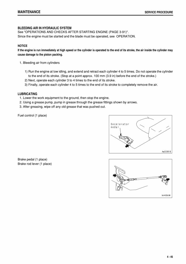
.
MAINTENANCE SERVICE PROCEDURE
BLEEDING AIR IN HYDRAULIC SYSTEMSee "OPERATIONS AND CHECKS AFTER STARTING ENGINE (PAGE 3-91)".Since the engine must be started and the blade must be operated, see OPERATION.
NOTICEIf the engine is run immediately at high speed or the cylinder is operated to the end of its stroke, the air inside the cylinder maycause damage to the piston packing.
1. Bleeding air from cylinders
1) Run the engine at low idling, and extend and retract each cylinder 4 to 5 times. Do not operate the cylinderto the end of its stroke. (Stop at a point approx. 100 mm (3.9 in) before the end of the stroke.)
2) Next, operate each cylinder 3 to 4 times to the end of its stroke. 3) Finally, operate each cylinder 4 to 5 times to the end of its stroke to completely remove the air.
LUBRICATING 1. Lower the work equipment to the ground, then stop the engine. 2. Using a grease pump, pump in grease through the grease fittings shown by arrows. 3. After greasing, wipe off any old grease that was pushed out.
Fuel control (1 place)
Brake pedal (1 place)Brake rod lever (1 place)
4 - 45

.
MAINTENANCESERVICE PROCEDURE MAINTENANCESERVICE PROCEDURE
Steering, directional, gearshift lever rotating link (4 places)
4 - 46

.
MAINTENANCE SERVICE PROCEDUREMAINTENANCE SERVICE PROCEDURE
Universal joint (2 places)
WARNINGThe undercover is heavy. Never try to open or close the cover when directlybeneath it. When removing bolts(2), carry out the work from the rear of thecover so that you can easily get out of the way.
Remove inspection cover (3) of the undercover on the rear bottomof the chassis as follows.
1) Remove 2 bolts (1) at the front of the machine. 2) Support the cover with your elbow while gradually
removing 2 bolts (2) at the rear of the machine. 3) Lower the cover gradually to open it.
4 - 47

.
MAINTENANCESERVICE PROCEDURE
CHECK BEFORE STARTINGFor details of the following items, see "CHECK BEFORE STARTING (PAGE 3-72)".
Checking with machine monitorCheck coolant level, add waterCheck fuel level, add fuelCheck oil level in engine oil pan, add oilCheck oil level in power train case (including transmission, torque converter and bevel gear cases), add oil.Check brake pedal travelCheck dust indicatorCheck oil level in hydraulic tank, add oilCheck electric wiringCheck that lamps light upCheck horn soundCheck backup alarm sound
4 - 48

.
MAINTENANCE SERVICE PROCEDURE
EVERY 250 HOURS SERVICE
LUBRICATING 1. Lower the work equipment to the ground, then stop the engine. 2. Using a grease pump, pump in grease through the grease fittings shown by arrows. 3. After greasing, wipe off any old grease that was pushed out.
(1) Blade lift cylinder support yoke (4 places)(2) Blade lift cylinder support shaft (2 places)
(3) Blade arm ball joint (3 places)(4) Brace screw (2 places)
(5) Ripper tilt cylinder bottom pin (2 places)(6) Ripper lift cylinder bottom pin (2 places)(7) Ripper tilt cylinder rod end pin (2 places)(8) Ripper lift cylinder rod end pin (2 places)(9) Ripper arm pin (front) (2 places)(10) Ripper arm pin (rear) (2 places)The sketch on the right shows the giant ripper (option).
4 - 49

.
MAINTENANCESERVICE PROCEDURE MAINTENANCESERVICE PROCEDURE
(11) Equalizer bar side shaft (2 places)
(12) Suspension (Equalizer bar center shaft) (1 place)1) Carry out greasing of the suspension (equalizer bar center
shaft) through the grease fittings marked by arrows.2) Pump the greasing lever up and down 3 to 5 times.
Fan pulley (1 place)
4 - 50

.
MAINTENANCE SERVICE PROCEDURE
CHECK, ADJUST ALTERNATOR DRIVE BELT TENSION
INSPECTIONPress the belt with a thumb midway between the alternator pulleyand drive pulley. The following are the standard deflections.When replacing with new belt: 19 - 21 mm (0.7 - 0.8 in) (approx. 10kg)When adjusting tension: 24 - 26 mm (0.9 - 1.0 in) (approx. 10 kg)
ADJUSTMENT 1. Loosen nuts (1) and (4) and bolt (2), then move alternator (3)
to adjust the belt tension to standard value.When adjusting the V-belt, do not push alternator (3)directly with the bar. Use nut (1).
2. Tighten nuts (1) and (4) and bolt (2) to hold alternator (3) inposition.
3. Check for damage to the pulleys, and wear of the V-groove and V-belt. Be particularly careful to check that theV-belt is not in contact with the bottom of the V-groove.
4. If any belt has stretched and there is no allowance for adjustment, or if there are cuts or cracks on any belt,replace the belt.
5. After replacing the belt, operate for one hour, then adjust again.
4 - 51

.
MAINTENANCESERVICE PROCEDURE
CHECK LEVEL OF BATTERY ELECTROLYTECarry out this procedure before operating the machine.
WARNINGDo not use the battery if the battery electrolyte level is below the LOWER LEVEL line. This will accelerate deterioration of theinside of the battery and reduce the service life of the battery. In addition, it may cause an explosion.The battery generates flammable gas and there is danger of explosion, do not bring fire or sparks near the battery.Battery electrolyte is dangerous. If it gets in your eyes or on your skin, wash it off with a large amount of water and consult adoctor.When adding distilled water to the battery, do not allow the battery electrolyte to go above the UPPER LEVEL line. If theelectrolyte level is too high, it may leak and cause damage to the paint surface or corrode other parts.
NOTICEIf there is a fear that the battery water may freeze after refilling with purified water (e.g. commercially available replenishment waterfor a battery), do the replenishment before the day's work on the next day.
Inspect the battery electrolyte level at least once a month and follow the basic safety procedures given below. Open cover (1) at the rear left side of the machine. The batteriesare installed at (A) part.
WHEN CHECKING ELECTROLYTE LEVEL FROM SIDE OF BATTERYIf it is possible to check the electrolyte level from the side of the battery, check as follows. 1. Use a wet cloth to clean the area around the electrolyte level
lines and check that the electrolyte level is between theUPPER LEVEL (U.L.) and LOWER LEVEL (L.L.) lines.If the battery is wiped with a dry cloth, static electricity maycause a fire or explosion.
4 - 52

.
MAINTENANCE SERVICE PROCEDUREMAINTENANCE SERVICE PROCEDURE
2. If the electrolyte level is below the midway point between theU.L and L.L lines, remove cap (1) and add distilled water to theU.L line.
3. After adding distilled water, tighten cap (1) securely.
REMARKIf distilled water is added to above the U.L. line, use a pipette tolower the level to the U.L. line. Neutralize the removed fluid withbaking soda (sodium bicarbonate), then flush it away with a largeamount of water or consult your Komatsu distributor or batterymaker.
4 - 53

.
MAINTENANCESERVICE PROCEDURE
WHEN IT IS IMPOSSIBLE TO CHECK ELECTROLYTE LEVEL FROM SIDE OF BATTERYIf it is impossible to check the electrolyte level from the side of the battery, or there is no display of the UPPERLEVEL line on the side of the battery, check as follows. 1. Remove cap (1) at the top of the battery, look through the water
filler port, and check the electrolyte surface. If the electrolytedoes not reach the sleeve, add distilled water so that the levelreaches the bottom of the sleeve (UPPER LEVEL line) withoutfail.
Use the diagram below for reference, and check if the electrolyte reaches the bottom of the sleeve.
2. After adding distilled water, tighten cap (1) securely.
REMARKIf distilled water is added to above the bottom of the sleeve, use a pipette to lower the level to the bottom of thesleeve. Neutralize the removed fluid with baking soda (sodium bicarbonate), then flush it away with a large amountof water or consult your Komatsu distributor or battery maker.
WHEN IT IS POSSIBLE TO USE INDICATOR TO CHECK ELECTROLYTE LEVELIf it is possible to use an indicator to check the electrolyte level, follow the instructions given.
4 - 54

.
MAINTENANCE SERVICE PROCEDURE
CHECK BRAKE PERFORMANCE
WARNINGIf the machine moves during the following operation, please contact your Komatsu distributor for repairs immediately.
NOTICEDo not place the joystick in the 1st speed position.Otherwise, it will cause damage to the machine.
Before starting the engine, check that the area around the machine is safe, then do as follows: 1. Start the engine. 2. Start the engine, and after completing the warming-up operation, set fuel control dial (7) to the SLOW position. 3. Set control lever (1) to the FREE position then operate blade
control lever (2) and ripper control lever (3) to raise the bladeand ripper.Leave the control lever (1) to the FREE position.
4. Set parking brake lever (1) to the FREE position. 5. Depress brake pedal (5), set joystick (6) in FORWARD, then
press the shift up button to enter 2nd speed. 6. Operate fuel control dial (7) and gradually raise the engine
speed to full throttle. (Keep the brake pedal depressed.) 7. Check that the machine does not move. This indicates that
brake performance is normal.
4 - 55

.
MAINTENANCESERVICE PROCEDURE
CHECK OIL LEVEL IN DAMPER CASE, ADD OIL 1. Remove dipstick (G), and wipe the oil off with a cloth. 2. Insert dipstick (G) fully in the oil filler pipe, then take it out again. 3. The oil level should be between the H and L marks on dipstick
(G).If the oil is below the L mark, add oil through the dipstick holder.
4. If the oil is above the H mark, drain the excess oil from drainplug. After draining the oil, check the oil level again.
REMARKCheck the oil level with the engine stopped.When checking the oil level, if the machine is at an angle, moveit to a horizontal position before carrying out the check.
4 - 56

.
MAINTENANCE SERVICE PROCEDURE
EVERY 500 HOURS SERVICEMaintenance for every 250 hours service should be carried out atthe same time.
CHANGE OIL IN ENGINE OIL PAN, REPLACE ENGINE OIL FILTER CARTRIDGE AND BYPASS FILTER CARTRIDGE
WARNINGThe oil is at high temperature after the engine has been operated, so never change the oil immediately after finishing operations.Wait for the oil to cool down before changing it.
Refill capacity: 55.5 liters (14.66 US gal)Socket wrench, filter wrench.
1. Open cover on the under the chassis. Set a container to catchthe oil under the drain valve (2).
2. Remove drain plug (1) and loosen drain valve (2) slowly toavoid getting oil on yourself, and drain the oil.Take care not to loosen drain valve (2) so much that thestopper pin in the valve is distorted.Tightening torque for drain plug (1): 68.6 ± 9.81 Nm
(7 ± 1 kgm, 50.6 ± 7.2 lbft)Tightening torque for drain valve (2): 63.7 ± 14.7 Nm (6.5 ± 1.
5 kgm, 47.0 ± 10.8 lbft) 3. Check the drained oil, and if there are excessive metal
particles or foreign material, please contact your Komatsudistributor.
4. Tighten drain valve (2).
4 - 57

.
MAINTENANCESERVICE PROCEDURE MAINTENANCESERVICE PROCEDURE
5. Using the filter wrench, turn full-flow filter cartridge (3) to the leftand remove it.
6. Clean the filter holder, fill the new filter cartridge with engine oil,coat the packing surface and thread with engine oil (or coat itthinly with grease), then install the filter cartridge.
7. When installing the filter cartridge, bring the packing surfaceinto contact with the filter holder, then tighten a further 3/4 to 1turn.
8. After replacing the filter cartridge, add engine oil through oilfiller port (F) until the oil level is between the H and L marks onthe dipstick.
9. Run the engine at idling for a short time, then stop the engine,and check that the oil level is between the H and L marks on thedipstick. For details, see "CHECK OIL LEVEL IN ENGINE OILPAN, ADD OIL (PAGE 3-75)".Even if the machine has not been operated for 500 hours, theoil and filter cartridge must be replaced when the machine hasbeen operated for 12 months.In the same way, even if the machine has not been operatedfor 12 months, the oil and filter cartridge must be replacedwhen the machine has been operated for 500 hours.
4 - 58

.
MAINTENANCE SERVICE PROCEDURE
REPLACE FUEL FILTER CARTRIDGE
WARNINGAfter the engine has been operated, all parts are at high temperature, so do not replace the filter immediately. Wait for all partsto cool down before starting the operation.High pressure is generated inside the engine fuel piping system when the engine is running.When replacing the filter, wait for at least 30 seconds after stopping the engine to let the internal pressure go down beforereplacing the filter.Do not bring any fire or flame close.
NOTICEGenuine Komatsu fuel filter cartridges use a special filter that has highly efficient filtering ability. When replacing the filtercartridge, always use a genuine Komatsu part.The HPI fuel injection system used on this machine consists of more precise parts than the conventional injection pump andnozzle.If any part other than a genuine Komatsu filter cartridge is used, dust or dirt may get in and cause problems with the injectionsystem. Always avoid using substitute parts.When carrying out inspection or maintenance of the fuel system, pay more attention than normal to the entry of dirt. If dirt isstuck to any part, use fuel to wash it off completely.
Container to catch the oilPrepare a filter wrench
1. Set the container to catch the fuel under the filter cartridge.The fuel filter is found by opening the engine side cover onthe left of the machine.
2. Close fuel supply valve (2) at the bottom of the fuel tank at therear of the machine.
3. Using a filter wrench, turn filter cartridge (1) counterclockwiseon remove it.
4. Clean the filter holder, fill the new filter cartridge with clean fuel,coat the packing surface thinly with oil, then install to the filterholder.
NOTICEWhen filling with fuel, use clean fuel and be careful not to let any dirt or dustget in. In particular, the center area is the clean side, so be careful not tolet dirt or dust get in. 5. When installing, tighten until the packing surface contacts the seal surface of the filter holder, then tighten it up
1/2 to 3/4 of a turn.If the filter cartridge is tightened too far, the packing will be damaged and this will lead to leakage of fuel. If thefilter cartridge is too loose, fuel will also leak from the packing, so always tighten to the correct amount.
4 - 59

.
MAINTENANCESERVICE PROCEDURE MAINTENANCESERVICE PROCEDURE
6. With this machine, it is unnecessary to bleed the air. Aftercarrying out the operations in Steps 1 - 5, turn the startingswitch to the START position and start the engine.
NOTICEDo not crank the starting motor continuously for more than 20 seconds. Ifthe engine does not start, wait for at least two minutes before trying to startagain.
REMARKIf the fuel piping has been removed, bleed the air also from the injection pump air bleed valve.
4 - 60

.
MAINTENANCE SERVICE PROCEDURE
REPLACE TRANSMISSION FILTER ELEMENT AND TORQUE CONVERTER OIL FILTER ELEMENT
WARNINGBefore opening the filter cases, depress the brake pedal several times to release the pressure, then lock the brake pedal. If thereis still pressure inside the filter, the oil may spurt out.
1. Remove the floor cover (A) on right side fender. (B) : Torque converter oil filter element (C) : Replace transmission filter element
2. Remove bolts (1) of torque converter filter (B) and transmissionfilter (C), then pull up cover (2) and take out element (3). Washthe inside of the case and the removed parts, then install a newelement. Replace the O-ring at the same time.
4 - 61

.
MAINTENANCESERVICE PROCEDURE
CHECK OIL LEVEL IN FINAL DRIVE CASE, ADD OIL
WARNINGThere is danger that the oil may spurt out under internal pressure, so to the side, and gradually turn the plug to release the internalpressure before removing the plug completely.
1. Place the machine on a horizontal place. 2. Remove oil level plug (G) and check whether the final drive
case is filled with oil to lower edge of the plug hole.
REMARKThere is a cast OIL LEVEL display on the cover, but there is noneed to return it to the horizontal position.
3. If the oil level is still too low, add gear oil through oil filter plughole (F) until the oil overflows.Before removing oil plug (F), remove all the mud and dirt fromaround oil filler plug (F). Be careful not to let any dirt or sand getin when adding oil.
4 - 62

.
MAINTENANCE SERVICE PROCEDURE
CHECK, REPLACE FAN BELTCheck the V-belt, and replace the V-belt if the condition is as follows.
If the V-belt is in contact with the bottom of the pulley groove.If the V-belt is worn and has sunk below the outside diameter of the pulley.If the V-belt is cracked or peeling.
REPLACEMENT 1. Loosen stopper bolt (1). After loosening it so that the tip of the
bolt is level with surface (A) of tension bracket (2), remove theold fan belts.
2. Temporarily install the 3 new fan belts. 3. Tighten stopper bolt (1) until it contacts surface (B) of tension
bracket (2). 4. After it contacts surface (B), tighten it a further 2 turns, then
tighten locknut (3) to lock it in position.Tightening torque of bolt: 7 Nm {25 - 31.5 kgm}
Always replace the V-belts as a set (3 belts).
4 - 63

.
MAINTENANCESERVICE PROCEDURE
EVERY 1000 HOURS SERVICEMaintenance for every 250 and 500 hours service should be carried out at the same time.
CHANGE OIL IN POWER TRAIN CASE, CLEAN STRAINERS (INCL. TRANSMISSION CASE, TORQUE CONVERTER CASE AND BEVEL GEAR CASE)
WARNINGThe oil is at high temperature immediately after the machine has been operated. Wait for the oil to cool down before startingthe operation.The undercover is heavy. Never open and close operation right below the undercover. When removing bolts, work behind theright below and be ready for escaping at any time.
Container to catch drained oil: Min 150 liters (39.6 US gal) capacityRefill capacity: 150 liters (39.6 US gal)
1. Remove the cover on the bottom of the rear body.
2. Pull out hose (1) slowly to avoid getting oil on yourself, andloosen drain plug (2) to drain the oil.
3. After draining, tighten drain plug (2). 4. Insert hose (1) inside the cover, then install the cover.
4 - 64

.
MAINTENANCE SERVICE PROCEDUREMAINTENANCE SERVICE PROCEDURE
5. Remove the cover on left fender, remove bolts (3) and case (4). 6. Take out strainer (5) and magnet (6).
If any damage to strainer (5) or magnet (6) is found, replacewith a new one.
7. Loosen bolt (7), then divide into strainer (5) and magnet (6).Tightening torque of bolt (7): 46 to 59 Nm (4.7 to 5.9 kgm, 34
to 43 lbft) 8. Remove all dirt from strainer, then wash in clean diesel oil or
flushing oil.Clean the case interior and the removed parts.
9. Install the strainers to their original position.10. After installing, replace the transmission and torque converter
filter elements. For details, see "REPLACE TRANSMISSIONFILTER ELEMENT AND TORQUE CONVERTER OILFILTER ELEMENT (PAGE 4-61)".
11. Refill the specified quantity of oil through oil filler (F).12. Check that the oil is at the specified level.
For details, see "CHECK OIL LEVEL IN POWER TRAINCASE (INCL. TRANSMISSION, TORQUE CONVERTERAND BEVEL GEAR CASES), ADD OIL (PAGE 3-76)".
4 - 65

.
MAINTENANCESERVICE PROCEDURE
CHECK, CLEAN FUEL STRAINER 1. Remove cover (1) at the bottom of the fuel tank at the rear of
the machine. (6 bolts) 2. Close fuel supply valve (2).
3. Remove cap (3), then wash the strainer and strainer case.The strainer forms one unit with cap (3).
4. After checking and cleaning, install the strainer, then tightencap (3).
5. Install the strainer, then open fuel supply valve (2). 6. Install cover (1).
CLEAN STEERING CLUTCH CASE BREATHER 1. Remove cover (2) at the bottom of the fuel tank at the rear of
the machine. (6 bolts (1))
2. Remove breather (3) on steering clutch case, and wash outdust remaining inside with diesel fuel or flushing oil.
4 - 66

.
MAINTENANCE SERVICE PROCEDURE
CHECK OIL LEVEL IN RECOIL SPRING, ASSIST CYLINDER CASE, ADD OIL 1. Remove bolts (1), then remove cover (2).
When removing the cover, be careful not to let dirt or sand getin.
2. Insert a scale and check that the oil level is 70 - 80 mm (2.6 to3.2 in) from the bottom edge of the inspection port.
3. If the oil level is low, add engine oil so that the oil.Use Class CD SAE10 engine oil regardless of the ambienttemperature.
LUBRICATE TENSION PULLEY ASSEMBLY 1. Using a grease pump, apply grease to the grease fitting
marked by the arrow. The grease fitting is at the top of the fuelfilter on the left side of the machine.
2. After greasing, wipe off any old grease that was pushed out.
CHECK FOR LOOSE ROPS MOUNT BOLTSCheck for loose and damaged bolts. If any loose bolt is found,tighten to a torque of 1520 to 1912 Nm (155 to 195 kgm, 1121 to1410 lbft).If any damaged bolt is found, replace the bolt with a genuineKomatsu bolt.
4 - 67

.
MAINTENANCESERVICE PROCEDURE
REPLACE CORROSION RESISTOR CARTRIDGE
WARNINGIf the engine has been operated, all parts will be at a high temperature, sonever try to replace the cartridge immediately after stopping the engine.Always wait for the engine and other parts to cool down.
Container to catch drained coolantPrepare a filter wrench for fuel filter element.
1. Tighten 2 valves (1). 2. Set a container to catch the coolant under the cartridge. 3. Using a filter wrench, remove cartridge (2). 4. Clean the filter holder, coat the packing surface and thread of
the new cartridge with oil, then install it to the filter holder. 5. When installing, tighten until the packing surface contacts the
seal surface of the filter holder, then tighten it up 2/3 of a turn.If the filter cartridge is tightened too far, the packing will bedamaged and this will lead to leakage of coolant.If the filter cartridge is too loose, coolant will also leak from thepacking, so always tighten to the correct amount.
6. Open valves (1) (2 places). 7. After replacing the cartridge, start the engine and check for any
leakage of water from the filter seal surface. If there is anywater leakage, check if the cartridge is tightened properly.
CHECK TIGHTENING PARTS OF TURBOCHARGERPlease contact your Komatsu distributor to have the tightening portions checked.
4 - 68

.
MAINTENANCE SERVICE PROCEDURE
EVERY 2000 HOURS SERVICEMaintenance for every 250, 500, and 1000 hours service should be carried out at the same time.
CHANGE OIL IN HYDRAULIC TANK, REPLACE HYDRAULIC OIL FILTER ELEMENT
WARNINGThe oil is at high temperature immediately after the machine has been operated. Wait for the oil to cool down before changingthe oil.When removing the oil filler cap (F), turn it slowly to release the internal pressure, then remove it carefully.
Refill capacity: 120 liters (31.70 US gal) 1. Lower the blade and ripper on the ground securely, stop the
engine and slowly turn the cap of oil filler (F) to release theinternal pressure. Then, remove the cap.
2. Remove drain plug (1) at the bottom of the tank and loosendrain valve (2). After draining the oil, tighten drain plug (1) anddrain valve (2). When loosening drain valve (1), be careful notto get oil on yourself.
4 - 69

.
MAINTENANCESERVICE PROCEDURE MAINTENANCESERVICE PROCEDURE
3. Pull up bolt (3) and cover (4), then remove element (6) togetherwith the valve and cover.After removing bolt (3), remove cover (4), then take outelement (6).
4. Remove nut (5) holding element (6), clean the case and theremoved parts, then install the new element.
5. Add engine oil through oil filler port (F) to the specified level. 6. After adding oil, check that the oil is at the specified level. For
details, see "CHECK OIL LEVEL IN HYDRAULIC TANK, ADDOIL (PAGE 3-78)".
4 - 70
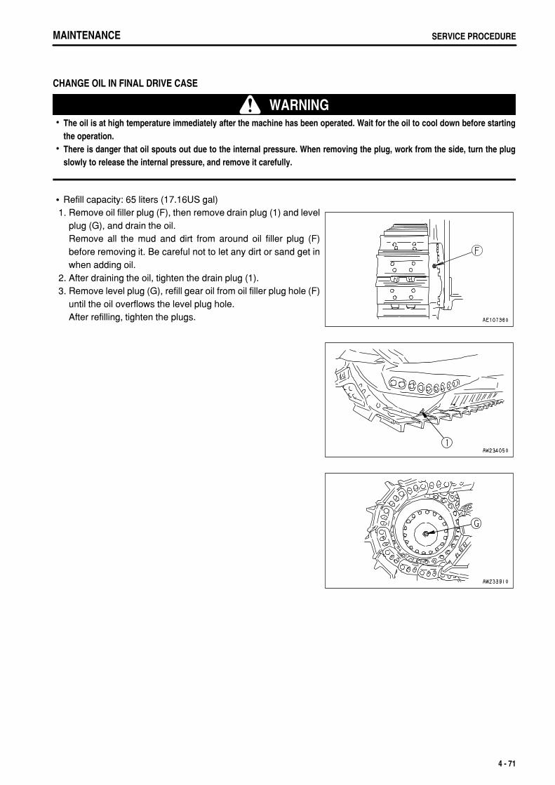
.
MAINTENANCE SERVICE PROCEDURE
CHANGE OIL IN FINAL DRIVE CASE
WARNINGThe oil is at high temperature immediately after the machine has been operated. Wait for the oil to cool down before startingthe operation.There is danger that oil spouts out due to the internal pressure. When removing the plug, work from the side, turn the plugslowly to release the internal pressure, and remove it carefully.
Refill capacity: 65 liters (17.16US gal) 1. Remove oil filler plug (F), then remove drain plug (1) and level
plug (G), and drain the oil.Remove all the mud and dirt from around oil filler plug (F)before removing it. Be careful not to let any dirt or sand get inwhen adding oil.
2. After draining the oil, tighten the drain plug (1). 3. Remove level plug (G), refill gear oil from oil filler plug hole (F)
until the oil overflows the level plug hole.After refilling, tighten the plugs.
4 - 71

.
MAINTENANCESERVICE PROCEDURE
CHANGE OIL IN DAMPER CASE AND BREATHER FILTER, CLEAN DAMPER BREATHER
WARNINGThe oil is at high temperature immediately after the machine has been operated. Wait for the oil to cool down before changing theoil.
Refill capacity: 2.1 liters (0.55 US gal) 1. Remove breather (4) at the top of the damper. 2. Wash out dust remaining inside of breather with diesel oil and
flushing oil. 3. Install breather (4) to the original position.
4. Remove slit plate (3), breather filter (5) and holder (6) on theupper part of the damper cover.
5. Wipe off dusts stuck to the slit plate and holder and then washthem with clean light oil or detergent liquid.Replace the filter with a new one.
6. Open the inspection cover under the chassis. 7. Remove drain plug (2) slowly to avoid getting oil on yourself,
and drain the oil.After draining the oil, tighten plug (2).
8. Pull out dipstick (1), and add oil to the specified level throughoil filler.
9. Check that the oil level is between the H and L marks ondipstick. For details, see "CHECK OIL LEVEL IN DAMPERCASE, ADD OIL (PAGE 4-56)".
10. Close the inspection cover.
4 - 72

.
MAINTENANCE SERVICE PROCEDURE
CHECK PIVOT BEARING OIL LEVEL, ADD OIL 1. Remove plug (1).
When removing plug (1), be careful not to let dirt or dust get it.
2. Check that the oil is at the level shown in the diagram. If the oillevel is low, add engine oil through the hole of plug (1).Use class CD SAE 30 engine oil regardless of the ambienttemperature.
CLEAN ENGINE BREATHER ELEMENT 1. Loosen clamp (1), then remove the hose. 2. Remove bolt (2), then remove breather (3). 3. Wash the whole breather in diesel oil or flushing oil, then blow
it dry with compressed air. 4. Replace the breather O-ring with a new part, coat with engine
oil, and install it.Check the breather hose, and if there is any oil sludge on theinside, replace it with a new hose.
CLEAN AND CHECK TURBOCHARGERContact your Komatsu distributor for cleaning or inspection.
CHECK PLAY OF TURBOCHARGER ROTORPlease contact your Komatsu distributor to have the rotor play checked.
4 - 73

.
MAINTENANCESERVICE PROCEDURE
CHECK ALTERNATOR, STARTING MOTORThe brush may be worn or the bearing may have run out of grease, so contact your Komatsu distributor forinspection or repair.If the engine is started frequently, have this inspection carried out every 1000 hours.
CHECK ENGINE VALVE CLEARANCE, ADJUSTAs special tool is required for removing and adjusting the parts, you shall request Komatsu distributor for service.
CHECK, ADJUST INJECTOR SET LOAD OF ENGINE(ONLY AFTER THE 2000 HOURS)As special tool is required for checking and adjusting the parts, request Komatsu distributor for service.
4 - 74
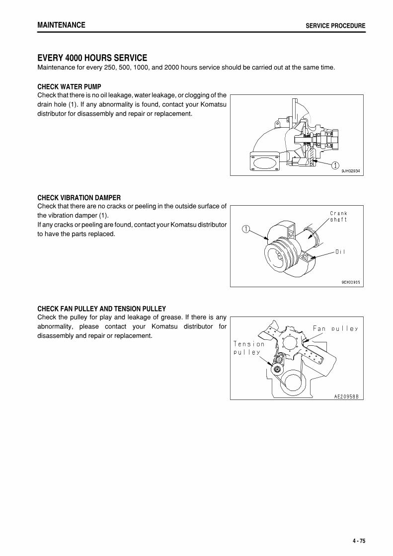
.
MAINTENANCE SERVICE PROCEDURE
EVERY 4000 HOURS SERVICEMaintenance for every 250, 500, 1000, and 2000 hours service should be carried out at the same time.
CHECK WATER PUMPCheck that there is no oil leakage, water leakage, or clogging of thedrain hole (1). If any abnormality is found, contact your Komatsudistributor for disassembly and repair or replacement.
CHECK VIBRATION DAMPERCheck that there are no cracks or peeling in the outside surface ofthe vibration damper (1).If any cracks or peeling are found, contact your Komatsu distributorto have the parts replaced.
CHECK FAN PULLEY AND TENSION PULLEYCheck the pulley for play and leakage of grease. If there is anyabnormality, please contact your Komatsu distributor fordisassembly and repair or replacement.
4 - 75

.
MAINTENANCESERVICE PROCEDURE
CHECK MAIN FRAME, WORK EQUIPMENT (BLADE, RIPPER)Check after the first 4000 hours, and every 1000 hours after that.
PreparationWipe off all the mud that is stuck around portions (A) - (L) of thework equipment and frame to make it easier to carry out the check.
Visual checkCarefully check the base material of the steel casting and weldingat portions (A) - (L), and check that there is no damage.If any cracks or other damage are found, carry out repairs.Please contact your Komatsu distributor for details of the repairprocedure.
4 - 76

.
MAINTENANCE SERVICE PROCEDURE
4 - 77

.

.
5 - 1

.
SPECIFICATIONSSPECIFICATIONS
SPECIFICATIONS
Item UnitD375A-5
Semi-U tilt dozer U tilt dozer
Operating weight (without operator) kg(lb) 68,500 (151,043) *1
Blade unit weight (including cylinder) kg(lb) 10,540 (23,241) 11,790 (98,762)
Ripper unit weight kg(lb)6,720 (14,818)
(variable multi ripper)5,470 (12,061)(Giant ripper)
Name of engine - KOMATSU SA6D170E-3 diesel engine
Engine horsepower KW{HP}/rpm 391{525}/1,800
A Overall length mm(ft in) 10,040(32'11") 10,695 (35'1")
B Overall height mm(ft in) 4,230 (13'11")
C Overall width mm(ft in) 4,965 (16'3") 5,140 (16'10")
Travel speed (1st/2nd/3rd)Forward km/h(MPH) 3.8/6.8/11.8(2.4/4.2/7.3)
Reverse km/h(MPH) 5.1/9.2/15.8 (3.2/5.7/9.8)
[*1]: 610 mm (24 in) shoe, ROPS cab, air conditioner
5 - 2

.
6 - 1
.
ATTACHMENTS, OPTIONSGENERAL PRECAUTIONS
GENERAL PRECAUTIONS
PRECAUTIONS RELATED TO SAFETYIf attachments or options other than those authorized by Komatsu are installed, this will not only affect the life of themachine, but will also cause problems with safety.When installing attachments not listed in this Operation and Maintenance Manual, contact your Komatsu distributorfirst.If you do not contact Komatsu, we cannot accept any responsibility for any accidents or failures.
WARNINGGeneral precautions
Read the instruction manual for the attachment carefully, and do not use the machine before you understand the operationmethod completely.If you lose the instruction manual, be sure to order another copy from your Komatsu distributor.To prevent serious personal injury caused by misoperation, place your foot on the pedal only when operating the pedal.
Precautions for removal and installationWhen removing or installing an attachment, observe the following items and work safely.
Select a firm, level surface when installing or removing an attachment.When working in cooperation with one or more other workers, decide signs and observe them when carrying out the operation.When carrying a heavy part (25 kg (55 lb) or more), use a crane.When removing a heavy part, always place a support in position before removing it.When lifting a load with a crane, be particularly careful of the center of gravity.It is dangerous to carry out operations when the load has been raised by a crane. Always lower the load onto a stand and checkthat it is safe.When leaving an attachment removed or installing it, place it in a stable position to prevent it from falling over.Never go under a load raised by a crane.Always stand in a place which is safe even if the load should fall.
NOTICEQualifications are required to operate a crane. Never allow the crane to be operated by an unqualified person.For details of removal and installation operations, contact your Komatsu distributor.
6 - 2

.
ATTACHMENTS, OPTIONS SELECTION OF TRACK SHOE
SELECTION OF TRACK SHOE
SELECTION OF TRACK SHOESSelect suitable track shoes to match the operating conditions.
METHOD OF SELECTING SHOESIf a wider shoe than necessary is used, the load on the track will increase, and this will cause the shoes to bend, linksto crack, pins to break, shoe bolts to come loose, and various other problems.
Category Use Precautions when using Track shoe width
ABedrock,
normal soil
This shoe can be used for a wide range of work from crushedrock to general civil engineering work such as reclamation ofresidential land. There is no particular limit to its use.
610 mm (24 in)
B Normal soil
Use this shoe for general soil, such as where the main work isscraper work and pusher work, reclaiming land for golf courses,or stripping the overburden for coal mines. This shoe cannot beused on bedrock. On jobsites where there are rocks in the soil,be careful to avoid letting the machine mount the rocks.
610 mm (24 in)
C Soft soilUse this shoe on soft ground where the shoe in category "B"sinks into the ground. Do not use this shoe on jobsites wherethere are rocks in the soil.
710 mm (28 in)810 mm (32 in)
6 - 3
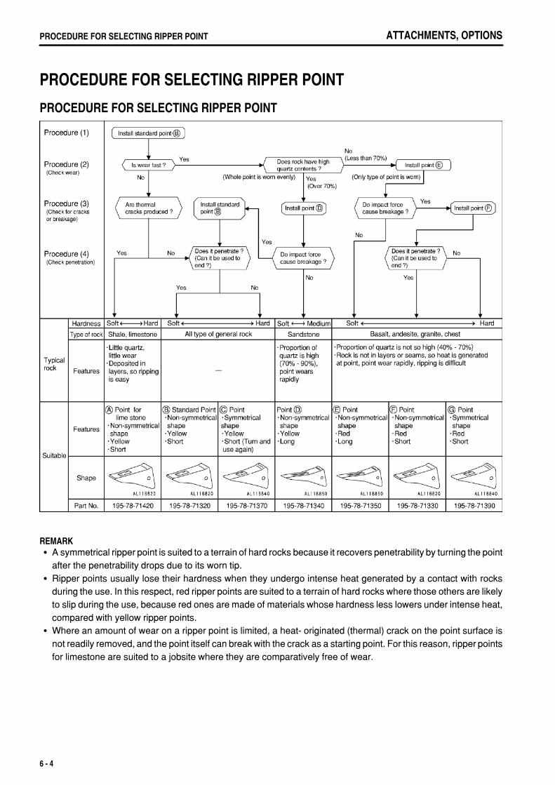
.
ATTACHMENTS, OPTIONSPROCEDURE FOR SELECTING RIPPER POINT
PROCEDURE FOR SELECTING RIPPER POINT
PROCEDURE FOR SELECTING RIPPER POINT
REMARKA symmetrical ripper point is suited to a terrain of hard rocks because it recovers penetrability by turning the pointafter the penetrability drops due to its worn tip.Ripper points usually lose their hardness when they undergo intense heat generated by a contact with rocksduring the use. In this respect, red ripper points are suited to a terrain of hard rocks where those others are likelyto slip during the use, because red ones are made of materials whose hardness less lowers under intense heat,compared with yellow ripper points.Where an amount of wear on a ripper point is limited, a heat- originated (thermal) crack on the point surface isnot readily removed, and the point itself can break with the crack as a starting point. For this reason, ripper pointsfor limestone are suited to a jobsite where they are comparatively free of wear.
6 - 4

.
ATTACHMENTS, OPTIONS CAP WITH LOCK, HANDLING
CAP WITH LOCK, HANDLING
METHOD OF OPENING AND CLOSING CAP WITH LOCKLock-type caps are available for the radiator water filler cap, fuel tank filler cap, power train case oil filler cap,hydraulic tank oil filler cap, and hydraulic tank breather cap. The cap opening and closing method is as follows.
TO OPEN THE CAP 1. Insert the key. Make sure that you have inserted the key fully
before turning it. If the key is turned when only partiallyinserted, it may break.
2. Turn the key counterclockwise to align the match mark on thecap with the rotor groove, then turn the cap slowly. When aclick is heard, the lock is released, enabling the cap to beopened.
TO LOCK THE CAP 1. Turn the cap into place. 2. Turn the key clockwise and take the key out.
6 - 5

.
ATTACHMENTS, OPTIONSEFFECTIVE METHOD OF OPERATION FOR DUAL TILTDOZER
EFFECTIVE METHOD OF OPERATION FOR DUAL TILTDOZER
BLADE CONDITION
SINGLE TILTOperate single/dual tilt selector switch to the SINGLE position,then operate the tilt.Applicable operation
Normal operations
DUAL TILTOperate single/dual tilt selector switch to the DUAL position, thenoperate the tilt.Applicable operation
Digging up bouldersSide cutting operations (high places)Horizontal dozing operations form side slope (rough ground)Ditching work
R PITCH (PITCH BACK)Keep the pitch button pushed in and operate the left tilt.Applicable operation
HaulingDozing soft soil (filling)Leveling operations (spreading)Side-cutting operations
6 - 6

.
ATTACHMENTS, OPTIONS EFFECTIVE METHOD OF OPERATION FOR DUAL TILTDOZER
S PITCH (STANDARD)Normal operationsApplicable operation
Normal operations
F PITCH (PITCH DUMP)Keep the pitch button pushed in and operate the right tilt.Applicable operation
Digging natural ground and bed-rock (digging hard soil)Pushing soil over cliffsPushing-up soil(Reduces spillage of soil over the top surface of the blade, andreduces amount of soil carried back)
6 - 7

.
ATTACHMENTS, OPTIONSEFFECTIVE METHOD OF OPERATION FOR DUAL TILTDOZER
DOZING WORK
DOZING ON LEVEL GROUND, OR DOWNHILL
NATURAL GROUND, BEDROCK
WARNINGIf you feel that the situation is dangerous when dumping the soil, for safety reasons, use two movements to push the soil over theedge.
1. Dig with the F (Front) pitch, and when the load on the blade is approx. 80%, return to S (Straight) pitch andcontinue digging.
2. Set to R (Rear) pitch which gives a larger load, and haul the soil. Adjust the cutting angle to the most effectiveangle for rolling the soil.
3. Use F pitch to dump the soil.
6 - 8

.
ATTACHMENTS, OPTIONS EFFECTIVE METHOD OF OPERATION FOR DUAL TILTDOZER
FILLING, SOFT SOILCarry out digging in R pitch or S pitch, and haul in R pitch.
REMARKIf the digging is carried out in R pitch, there is no sudden digginginto the soil, and the operation can be carried out smoothly.
HARD SOIL (HARD CLAY, SHALE, ETC.)If digging is carried out in F pitch, and the chassis is raised and theblade is tilted, the end bit will dig in better.
6 - 9

.
ATTACHMENTS, OPTIONSEFFECTIVE METHOD OF OPERATION FOR DUAL TILTDOZER
PUSHING-UP SOIL
1. Dig with S pitch.When digging gradually, use R pitch.If the ground is hard, use F pitch.
2. Haul with R pitch.If there is any spillage of soil over the top of the blade, change to S pitch.
3. Dump the soil with F pitch.This dumps the soil more effectively, and less soil is carried back.
6 - 10

.
ATTACHMENTS, OPTIONS EFFECTIVE METHOD OF OPERATION FOR DUAL TILTDOZER
LEVELING (SPREADING) OPERATIONCarry out this operation with R itch.When carry out this operation with R pitch, the end bit does not digin, and the ground can be leveled ( or the soil can be spreadsmoothly.)
REMARKIf the tilt cylinder is moved completely to the end of its stroke, thetilt operation cannot be carried out on one side, so move thecylinder back slightly from the end of its stroke to the S pitchposition.
DITCHING OPERATIONIf the dual tilt is used, the digging width becomes smaller and adeeper ditch can be dug.If R pitch is used, the digging can be carried out gradually, and thisreduces the unevenness.
BOULDER RAISING OPERATIONBecause the dual tilt greatly increases the amount of tilt, the bladecan dig in deep and hook under the boulder. In addition, theoperating stroke is large, so operations to raise boulders can becarried out effectively.
6 - 11
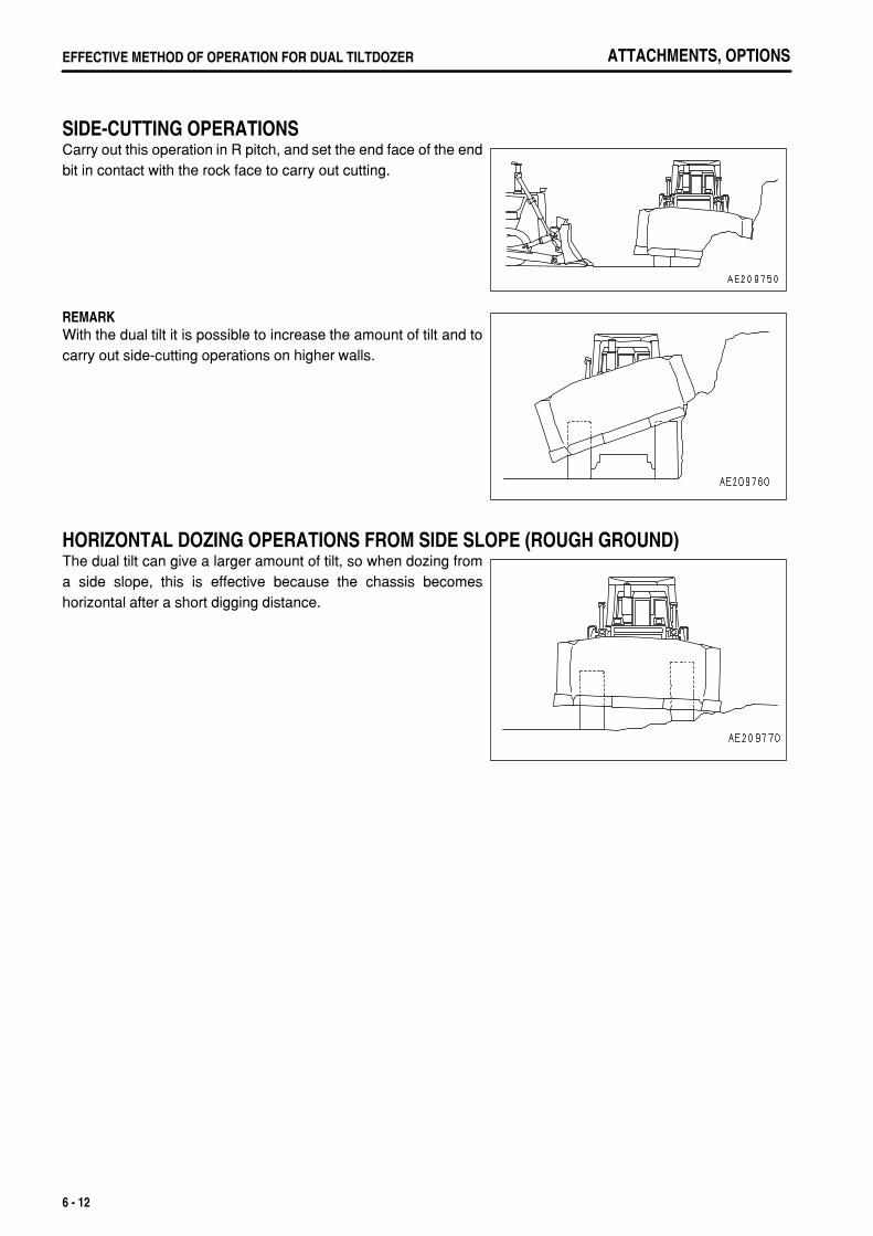
.
ATTACHMENTS, OPTIONSEFFECTIVE METHOD OF OPERATION FOR DUAL TILTDOZER
SIDE-CUTTING OPERATIONSCarry out this operation in R pitch, and set the end face of the endbit in contact with the rock face to carry out cutting.
REMARKWith the dual tilt it is possible to increase the amount of tilt and tocarry out side-cutting operations on higher walls.
HORIZONTAL DOZING OPERATIONS FROM SIDE SLOPE (ROUGH GROUND)The dual tilt can give a larger amount of tilt, so when dozing froma side slope, this is effective because the chassis becomeshorizontal after a short digging distance.
6 - 12

.
ATTACHMENTS, OPTIONS SHOE SLIP CONTROL
SHOE SLIP CONTROL
MODE SELECTION SWITCH PANEL (SHOE SLIP CONTROL)Press each mode switch to turn it ON or OFF and to select the mode.For details of setting the mode to use, see "EFFECTIVE USE OF MODE SELECTION SYSTEM (PAGE 3-114)".
The economy mode, reverse slow mode, and shoe slip control mode can be used independently or incombination.
(1) Shoe slip control switch (2) Rock selection mode selector switch
SHOE SLIP CONTROL SWITCHThis switch (1) is used for ripping operations.When it is switched ON, the lamp lights up.
NOTICEIf the shoe slip control is switched ON, the rock selection mode isautomatically set to [3], so switch the rock selection mode to match thetype of rock.
6 - 13

.
ATTACHMENTS, OPTIONSSHOE SLIP CONTROL
ROCK SELECTION MODE SELECTOR SWITCHUsing this switch (2) during ripping operations, turn the shoe slipcontrol ON and select mode [1] - [5] according to the shoe slipratio.The lamp for the selected mode lights up.
6 - 14

.
ATTACHMENTS, OPTIONS SHOE SLIP CONTROL
EFFECTIVE USE OF MODE SELECTION SYSTEM
(1)(2)(3)
Lock up mode switchEconomy mode selector switchReverse slow mode selector switch
(4)(5)
Shoe slip control switchRock selection mode selector switch
Selecting the mode to match the type of work and quality of rock or soil makes it possible to carry out operationseffectively.The condition when all the mode selection switches are off is called the standard mode.It is impossible to use any combination of the lock-up mode and any other mode.The economy mode, reverse slow mode, and shoe slip control mode can be used independently or in combination.
: Possible to use : Compound use not possible
6 - 15

.
ATTACHMENTS, OPTIONSSHOE SLIP CONTROL
SELECTION OF MODE
DOZING OPERATIONS
LOCK UP MODEBy using the lock up mode, the travel speed increases, theoperating efficiency is improved, and the fuel consumption is alsoreduced.
Speed ranges that can be used: All speed rangesApplicable operations: Dozing loose material (suitable for
long-distance hauling operations)When the lock up mode is turned ON, direct drive or torqueconverter drive are automatically selected according to the load.
(Example)Slot dozing operations
Hillside dozing operations
REMARKIf dozing operations power carried out on a slope of an angle ofmore than 15°, the lock-up may easily be canceled, sooperations are easier to carry out in the standard mode.For normal ripping operations, if the lock-up mode is used, thelock-up will switch repeatedly between ON and OFF, so use thestandard mode or shoe slip control mode.Even with ripping operations, if the ground is extremely soft, thelock-up mode can be used.
6 - 16

.
ATTACHMENTS, OPTIONS SHOE SLIP CONTROL
ECONOMY MODEUsing the economy mode makes it possible to reduce wastefulshoe slippage and to reduce the fuel consumption.
Speed ranges that can be used: F1Applicable operations: Hauling after ripping, dozing blasted
rock, smoothing.When the economy mode is turned ON, it is automatically set to [1].Carry out dozing operations in this condition, then set to [2] andcarry out operations. From this test, select the matching that givespower and low shoe slip ratio (frequency of decelerationoperation).Mode [1] is set to approx. 90% of full power and mode [2] is set toapprox 70%.(Example)
Fine leveling operations
Ripping and dozing operations
REMARKIf the shoe slip control switch is turned ON and the ripper is lowered during dozing operations in the standardmode, the system will enter the shoe slip control mode. If this happens, return to the N position, set the speedrange to F1, and this will return to the standard mode.If the economy mode and shoe slip control switches are turned ON and the ripper is lowered during dozingoperations in the economy mode, the system will enter the shoe slip control mode. If this happens, return to theN position, set the speed range to F1, and this will return to the standard mode.
6 - 17

.
ATTACHMENTS, OPTIONSSHOE SLIP CONTROL
RIPPING OPERATIONS
SHOE SLIP CONTROLThis makes it possible to reduce the frequency of operation of thedecelerator pedal by the operator, and contributes to reduction inoperator fatigue. It also prevents wasteful shoe slippage, improvesthe service life of the undercarriage, and reduces fuelconsumption.
Speed ranges that can be used: F1Applicable operations: Ripping
In normal ripping operations, the operator uses the deceleratorpedal to control the engine speed while carrying out ripping. If theshoe slip control is turned ON, the shoe slip control system aids theoperator in carrying out this control.When the shoe slip control switch is turned ON, the rock selectionmode is automatically set to [3].Carry out operations in this condition, and if the shoe slip ratio is toohigh, press a switch in the hard direction to set the mode to [4] or[5].If the shoe slip ratio is low and there seems to be lack of power,press the switch in the soft direction to set the mode to [2] or [1].
REMARKAfter the joystick is set to F1, the shoe slip control starts whenthe ripper lever is operated to LOWER or TILT. Even when theoperation alternates between dozing and ripping, there is noneed to turn the switch ON or OFF.With this system, if shoe slippage occurs during rippingoperations, the engine speed is lowered to prevent wastefulshoe slippage.If shoe slippage occurs during ripping operations and theengine speed goes down, if the ripper lever is operated to TILTIN or RAISE, the engine speed will rise (output is increased) tomake it easier to carry out breaking operations.When carrying out ripping operations on hard rock, if the rear ofthe machine comes off the ground and there is sudden shoeslippage, it is possible to reduce the shoe slippage by operatingthe ripper to LOWER and reducing the engine speed.
6 - 18

.
ATTACHMENTS, OPTIONS SHOE SLIP CONTROL
REVERSE SLOW MODEThis reduces the travel speed when traveling in reverse, reducesthe frequency of operating the decelerator pedal, and improves theriding comfort for the operator.
Speed ranges that can be used: R1, 2, 3(If this mode is only necessary when traveling in R2 or R3, it ispossible to change the setting of the service mode. To do this,please contact your Komatsu distributor.)
Applicable operations: Traveling on bedrock, traveling downsteep hills
Use this mode to reduce the travel speed when traveling in R1, R2,or R3.When the reverse slow mode is ON, the travel speed is set toapprox. 80% of the full travel speed.Use this mode to reduce the travel speed when traveling in reverseafter ripping and dozing bedrock or when traveling in reverse afterdozing on steep slopes. The travel speed differs in each modeaccording to whether it is used in combination with the economymode or with shoe slip control.When using shoe slip control, the travel speed for bedrock settingmodes [1] - [5] is set at approx. 70 - 90% of the full travel speed.
When traveling on bedrock, if it is felt that the travel speed whentraveling in reverse is too high, turn the reverse slow mode ON.This will reduce the travel speed when traveling in reverse.
When traveling down slopes, if it is felt that the travel speed whentraveling in reverse is too high, turn the reverse slow mode ON.This will reduce the travel speed when traveling in reverse.
6 - 19

.
ATTACHMENTS, OPTIONSSHOE SLIP CONTROL
PROCEDURE FOR SELECTING MODE ACCORDING TO NATURE OR NEEDS TO WORKUse the table below to select the mode that matches the nature or needs of the operation.
6 - 20
.
ATTACHMENTS, OPTIONS SHOE SLIP CONTROL
IF MODE SELECTION SYSTEM FLASHESIf the caution lamp flashes, or it becomes impossible to control the engine speed with the fuel control dial ordecelerator pedal, stop operation immediately, check the monitor panel display, then contact your Komatsudistributor for repairs.In addition to the above problems, if any of the problems in the table below occur, there is probably an abnormalityin the work equipment lever switch, transmission speed range sensor, or other part, so please contact your Komatsudistributor for repairs.
Mode Operation Abnormality
Shoe slip control Ripping
When shoe slip occurs, it is impossible to throttle powerEven when there is shoe slippage, it is impossible to controlAfter slippage stops, it takes a long time for power to recoverIt becomes difficult to break rock by operating lever to TILT or RAISETravel speed increases when shank is insertedTravel speed is slow and drawbar pull is lackingNo sense of control, engine stays at full or partialChassis flies when starting ripping
6 - 21

.

.
INDEX
INDEX
<A>ACCUMULATOR, HANDLING 3- 67ADJUSTING POSTURE OFWORK EQUIPMENT 3-126AIR CONDITIONER, HANDLING 3- 62ASHTRAY 3- 53
<B>BLADE SERIAL NO. PLATE POSITION 1- 9
<C>CAP WITH LOCK, HANDLING 6- 5 METHOD OF OPENING AND CLOSING CAP WITH LOCK 6- 5CAR STEREO, HANDLING 3- 54CHECK AFTER FINISHING WORK 3-111CHECK AFTER STOPPING ENGINE 3- 94CHECK BEFORE STARTING ENGINE,ADJUST 3- 70COLD WEATHER OPERATION 3-136 AFTER COLD WEATHER 3-139 AFTER COMPLETION OF WORK 3-137 PRECAUTIONS FOR LOW TEMPERATURE 3-136CONTROL LEVERS, PEDALS 3- 37CONTROLLER 3- 46
<D>DOOR OPEN LOCK 3- 52DOOR POCKET 3- 53DUST INDICATOR 3- 47
<E>EFFECTIVE METHOD OF OPERATIONFOR DUAL TILT DOZER 6- 6 BLADE CONDITION 6- 6 BOULDER RAISING OPERATION 6- 11 DITCHING OPERATION 6- 11 DOZING WORK 6- 8 HORIZONTAL DOZING OPERATIONS FROM SIDE SLOPE (ROUGH GROUND) 6- 12 LEVELING (SPREADING) OPERATION 6- 11 SIDE-CUTTING OPERATIONS 6- 12EFFECTIVE USE OFMODE SELECTION SYSTEM 3-114
ENGINE SERIAL NO. PLATEAND POSITION 1- 8EXPLANATION OF COMPONENTS 3- 5
<F>FOREWORD 1- 2FRONT PANEL 3- 5FRONT/REAR, LEFT/RIGHTDIRECTIONS OF MACHINE 1- 7FUSE BOX 3- 48FUSIBLE LINK 3- 51
<G>GENERAL PRECAUTIONS 2- 9GENERAL PRECAUTIONS 6- 2 PRECAUTIONS RELATED TO SAFETY 6- 2GENERAL VIEW 3- 2GENERAL VIEW OFCONTROLS AND GAUGES 3- 3GENERAL VIEW OF MACHINE 3- 2GUIDES TO MAINTENANCE 4- 2
<H>HANDLING MACHINES EQUIPPEDWITH VHMS 3- 68HANDLING OIL, FUEL, COOLANT,AND PERFORMING OIL CLINIC 4- 5
<I>INSTALLATION OF CAB 3-135INTRODUCTION 1- 7
<L>LOADING, UNLOADING WORK 3-132LOCKING 3-111LONG-TERM STORAGE 3-140 AFTER STORAGE 3-140 BEFORE STORAGE 3-140 DURING STORAGE 3-140 STARTING MACHINE AFTER LONG-TERM STORAGE 3-140
<M>MACHINE SERIAL NO. PLATEAND POSITION 1- 8MAINTENANCE SCHEDULE CHART 4- 17
7 - 1

.
INDEX
METHOD OF LIFTING MACHINE 3-133MOVING MACHINE 3- 95
<N>NECESSARY INFORMATION 1- 8
<O>OPERATING METHOD FORRIPPING OPERATIONS 3-122OPERATION 3- 70OPERATIONS AND CHECKSAFTER STARTING ENGINE 3- 91OUTLINE OF ELECTRIC SYSTEM 4- 8OUTLINES OF SERVICE 4- 5
<P>PARKING MACHINE 3-109PERIODIC REPLACEMENT OFSAFETY CRITICAL PARTS 4- 15POSITION OF SERVICE METER 1- 9POWER SOURCE 3- 47PRECAUTIONS FOR LOADING 3-132PRECAUTIONS FOR MAINTENANCE 2- 27PRECAUTIONS FOR OPERATION 2- 19 BATTERY 2- 24 BEFORE STARTING ENGINE 2- 19 OPERATION 2- 21 TOWING 2- 26 TRANSPORTATION 2- 24PRECAUTIONS FOR OPERATION 3-107PRECAUTIONS FORTRANSPORTATION 3-134PROCEDURE FORSELECTING RIPPER POINT 6- 4 PROCEDURE FOR SELECTING RIPPER POINT 6- 4
<R>RECOMMENDED FUEL, COOLANT,AND LUBRICANT 4- 11REMOVAL OF CAB 3-134RIPPER OPERATION 3-119RIPPER SERIAL NO. PLATE POSITION 1- 9
<S>SAFETY 2- 2SAFETY CRITICAL PARTS 4- 16SAFETY INFORMATION 1- 5SAFETY LABELS 2- 4 POSITIONS OF
SAFETY PICTOGRAMS 2- 4 SAFETY LABELS 2- 5SASH GLASS INTERMEDIATE LOCK 3- 52SELECTION OF TRACK SHOE 6- 3 SELECTION OF TRACK SHOES 6- 3SERVICE PROCEDURE 4- 19 CHECK BEFORE STARTING 4- 48 EVERY 1000 HOURS SERVICE 4- 64 EVERY 2000 HOURS SERVICE 4- 69 EVERY 250 HOURS SERVICE 4- 49 EVERY 4000 HOURS SERVICE 4- 75 EVERY 500 HOURS SERVICE 4- 57 INITIAL 250 HOURS SERVICE (ONLY AFTER THE FIRST 250 HOURS) 4- 19 WHEN REQUIRED 4- 20SHIFTING BETWEENFORWARD AND REVERSE 3-101SHIFTING GEAR 3- 98SHOE SLIP CONTROL 6- 13 EFFECTIVE USE OF MODE SELECTION SYSTEM 6- 15 IF MODE SELECTION SYSTEM FLASHES 6- 21 MODE SELECTION SWITCH PANEL (SHOE SLIP CONTROL) 6- 13SPECIFICATIONS 5- 2STANDARD TIGHTENING TORQUESFOR BOLTS AND NUTS 4- 14STARTING ENGINE 3- 88STEERING MACHINE 3-103STOPPING ENGINE 3- 94STOPPING MACHINE 3- 97SWITCHES 3- 33
<T>TABLE TO ENTER SERIAL NO.AND DISTRIBUTOR 1- 10TIPS FOR LONGERUNDERCARRIAGE LIFE 3-129TOOL BOX 3- 53TORQUE LIST 4- 14TRANSPORTATION 3-131TRANSPORTATION PROCEDURE 3-131TRAVELING ON ROADS 3-134TROUBLESHOOTING 3-141 AFTER RUNNING OUT OF FUEL 3-141 IF BATTERY IS DISCHARGED 3-142 METHOD OF TOWING MACHINE 3-141 OTHER TROUBLE 3-145
7 - 2

.
INDEX
WHEN MODE SELECTION SYSTEM FLASHES 3-150
<W>WEAR PARTS 4- 9WEAR PARTS LIST 4- 9WORK POSSIBLEUSING BULLDOZER 3-112
7 - 3

.
D375A-5 BULLDOZERForm No. TEN00196-03
©2008 KOMATSUAll Rights ReservedPrinted in Japan 03-08