Embed Size (px)
Citation preview
LANL Engineering Standards Manual ISD 341-2 Chapter 7, Electrical Section D5000 - General Electrical Requirements Rev. 3, 06/06/08
MANDATORY DOCUMENT
TABLE OF CONTENTS
D5000 GENERAL ELECTRICAL REQUIREMENTS
1.0 APPLICATION OF THIS CHAPTER ................................................................................................ 3 2.0 CODES AND STANDARDS ........................................................................................................... 5 3.0 COORDINATION OF DESIGN REQUIREMENTS ........................................................................... 11 4.0 DESIGN DOCUMENTATION ...................................................................................................... 12 5.0 SYSTEM REQUIREMENTS ......................................................................................................... 20 6.0 EQUIPMENT LOCATION ............................................................................................................ 23 7.0 ELECTRICAL IDENTIFICATION ................................................................................................. 26 8.0 ELECTRICAL SUPPORTS AND ANCHORAGE ............................................................................. 29 9.0 RODENT-PROOFING ................................................................................................................. 30 10.0 DEMOLITION ............................................................................................................................ 30 11.0 ACCEPTANCE TESTING ............................................................................................................ 31 12.0 ADDITIONAL REQUIREMENTS FOR SAFETY-RELATED ELECTRICAL SYSTEMS (PROGRAMMATIC AND FACILITY) ........................................................................................................ 35
Page 1 of 38
LANL Engineering Standards Manual ISD 341-2 Chapter 7, Electrical Section D5000 - General Electrical Requirements Rev. 3, 06/06/08
MANDATORY DOCUMENT
Page 2 of 38
record of revisions Rev Date Description POC OIC
0 11/18/02 General revision and addition of endnotes; added nuclear requirements. Replaces Subsections 201-202, 218, 219, 295.
David W. Powell, FWO-SEM
Kurt Beckman, FWO-SEM
1 6/9/04 Added programmatic requirements, new NECA and NETA installation and testing standards, requirement for electrical demolition drawings; clarified requirements for nuclear and hazardous facilities.
David W. Powell, FWO-DECS
Gurinder Grewal, FWO-DO
2 10/27/06 Administrative changes only. Organization and contract reference updates from LANS transition; 420.1A became 420.1B; NEC edition update; deleted NM Elec Code based on 9/18/06 variance IMP and ISD number changes based on new Conduct of Engineering IMP 341. Master Spec number/title updates. Other administrative changes.
David Powell, FM&E-DES
Kirk Christensen, CENG
3 06/06/08
References to codes and standards updated. Updated LANS contract references to state laws and regulations. Added reference to Section Z10 for design output requirements. Added references to ESM Chapters 14 and 16. Requirements for coordination studies for special electrical systems expanded. Added requirement for documented analysis to support decisions to modify (vs. replace) existing major electrical equipment. Added UPS and engine-generator load summaries on one-line diagram sheets. Provisions for future expansion of electrical systems clarified. Aligned arc-flash warning label requirements with LANL ISD 101-13 and NFPA 70E. Requirements for marking working spaces modified. Added graded approach to determine the extent of formal electrical acceptance testing.
David Powell, ES-DE
Kirk Christensen, CENG
LANL Engineering Standards Manual ISD 341-2 Chapter 7, Electrical Section D5000 - General Electrical Requirements Rev. 3, 06/06/08
D5000 GENERAL ELECTRICAL REQUIREMENTS
1.0 APPLICATION OF THIS CHAPTER
1.1 General Requirements
A. The National Electrical Code® (and similarly other codes and standards) contains provisions considered necessary to safety. Compliance with the applicable codes and proper maintenance of systems will result in installations that are free from hazard, BUT not necessarily efficient, convenient, or adequate for good service or future expansion of electrical use.1 The purpose of this chapter of the LANL Engineering Standards Manual (ESM) is to provide electrical systems that are free from hazard AND are efficient, convenient, and adequate for good service, maintainable, standardized, and adequate for future expansion of electrical use.
B. Electrical design, material, equipment, and installations shall comply with site-specific requirements in this Chapter and Chapter 1 of the ESM.2 Where appropriate, guidance is provided to aid the cost-effective implementation of site-specific requirements and the requirements in the applicable codes. Code requirements are minimum requirements that are augmented by the site-specific requirements in this chapter.
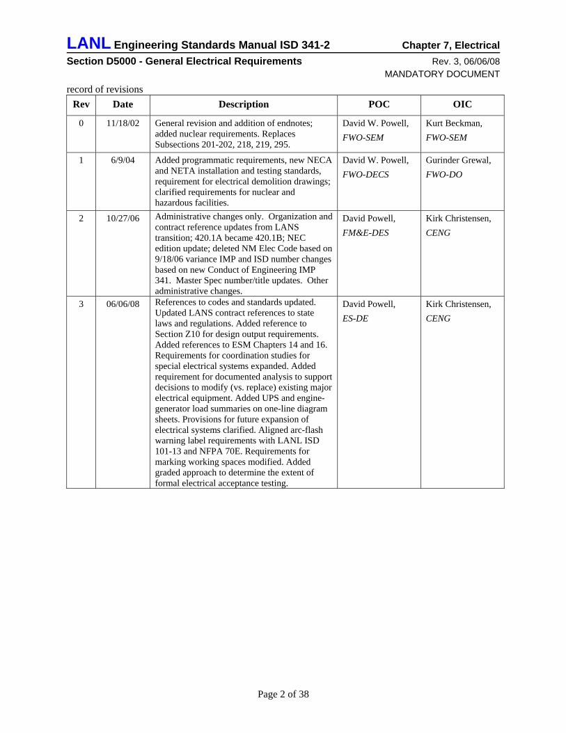
C. Figure D5000-1 illustrates the relationship of ESM Chapter 7 to Chapter 1 as well as the organization of the parts of Chapter 7.
Figure D5000-1, ESM Chapter 7 Organization
Chapter 1 General Requirements
for all Disciplines/Chapters
Chapter 7 Electrical
Chapter 7 Electrical Drawings
(Standard Details)
D5000 General Electrical
Requirements
D5010 Electrical Service
& Distribution Systems
D5020 Lighting & Branch
Circuit Wiring
D5030 Communication
D5090 Other Electrical
Systems
G4010 Site Electrical Distribution
G4020 Site Lighting
G4030 Site Communication
& Security
G4090 Other Site
Electrical Utilities
Engineering Standards Manual - Introduction
1 National Electrical Code®.Article 90.1 describes the purpose of the code. 2 LANL IMP 341, “Conduct of Engineering” is the implementation requirement document for this manual.
Page 3 of 38
LANL Engineering Standards Manual ISD 341-2 Chapter 7, Electrical Section D5000 - General Electrical Requirements Rev. 3, 06/06/08
D. Within this chapter, other than for titles of codes and standards, italicized text indicates provisions considered desirable but not mandatory. Recommendations are based on good business and engineering practice and lessons-learned at LANL. All other text in regular type indicates mandatory requirements unless prefaced with wording identifying it as guidance or recommended.
E. In addition to new electrical installations, this Chapter applies to all renovation, replacement, modification, maintenance, or rehabilitation projects for which the LANL Electrical Authority Having Jurisdiction3 (AHJ) requires a design.4 The LANL Electrical AHJ requires a design for all projects that include any of the following elements:
1. New or modified branch circuit exceeding 100 amps.
2. Branch circuit of any size when the grounding system integrity or existing or proposed panelboard loads is unknown.
3. New or modified feeder circuit, including installation of transformer.
4. New or modified service.
F. For repairs, alterations, or additions to existing facilities or systems, follow the LANL Existing Building/System Code (IEBC) described in Appendix B of ESM Chapter 16-IBC Program.
1.2 Definitions
A. Definitions of electrical terms in Chapter 7 are the same as those in the National Electrical Code®.5
B. Refer to ESM Chapter 1 Section Z10 for definitions of terms and acronyms used throughout the ESM.
C. The following are definitions of terms and acronyms peculiar to ESM Chapter 7:
1. Low voltage: a class of nominal system voltages less than 1000 V.6
2. Medium voltage – a class of nominal system voltages equal to or greater than 1000 V but less than 100,000 V. 6
3. High voltage: a class of nominal system voltages from 100,000 V to 230,000 V. 6
3 LANL ISD 101-13, “Electrical Safety,” establishes the LANL Electrical Safety Committee as the site-wide electrical authority having jurisdiction (AHJ). The Electrical Safety Committee delegates the day-to-day AHJ duties to the LANL Chief Electrical Safety Officer. 4 E-mail from Terry Fogle (LANL Chief Electrical Safety Officer) dated 13 October 1999 established criteria for when the LANL electrical AHJ requires an electrical design for LANL projects. (EMref 26) (Note: EMref refers to a ESM team system for managing hard-to-find reference hardcopies.) 5 Refer to NEC® Article 100. 6 Refer to IEEE Std 141, Chapter 3.
Page 4 of 38
LANL Engineering Standards Manual ISD 341-2 Chapter 7, Electrical Section D5000 - General Electrical Requirements Rev. 3, 06/06/08
D. The Electrical chapter shall be applied to programmatic systems and components as follows:
1. Headings in this Chapter followed by “Programmatic and Facility” indicate that subsection shall be complied with by all of LANL, including programs.
2. Guidance: Programmatic personnel should review all topics in the chapter for relevant material when initiating any design task.
3. Guidance: All programmatic electrical installations should be constructed with materials and components meeting either national standards (e.g., NEMA, ANSI, etc) or be Nationally Recognized Testing Laboratory (NRTL) listed equipment and material that is used in accordance with its listing for the intended purpose. In the case of departure from equipment listing parameters or when equipment is not available as NRTL listed, then the situation should be reviewed for the purpose by the LANL Electrical AHJ and the using organization’s Electrical Safety Officer. Exception: Equipment set-up and used for less than 180 days or that is intentionally destroyed during the experiment, and is constructed and operated by qualified technicians using approved procedures described in formal procedures or Hazard Control Plans.
2.0 CODES AND STANDARDS
2.1 General Requirements
A. Electrical design, material, equipment, and installation shall comply with the applicable portions of the latest edition of each code and standard listed below or referenced elsewhere in this chapter, in effect at the time of design contract award, unless otherwise noted in the Contract.
B. Refer to Chapter 1 Section Z10 for description and application of “Code of Record” system.
C. In many instances recommendations or “best practices’ in DOE orders, building codes, electrical codes, and industry standards have been adopted as requirements in this Chapter of the ESM.
D. If there is a conflict between codes, standards, and LANL requirements in this chapter, contact the ESM Discipline POC for assistance in resolving the conflict. If a requirement in the ESM exceeds a minimum code or standard requirement, it is not considered a conflict, but a difference; see also Chapter 1 Section Z10.
E. Where the NEC® uses terms similar to “by special permission,” obtain written permission from the LANL Electrical AHJ7.
2.2 LANS Contract (Programmatic and Facility)
A. The LANS Contract in Section I, page 45, clause I-123 (a) requires that work at LANL be performed in compliance with applicable State laws and regulations. The State of New
7 LANL ISD 101-13, “Electrical Safety,” paragraph 2.2.2 indicates that the Chief Electrical Safety Officer will issue clarifications and interpretations and approve alternate methods to the NEC®, NESC, and the LANL Electrical Safety Program.
Page 5 of 38
LANL Engineering Standards Manual ISD 341-2 Chapter 7, Electrical Section D5000 - General Electrical Requirements Rev. 3, 06/06/08
Mexico typically adopts the NEC plus some local amendments effective on or about July 1 of the edition year; such adoptions appear in the New Mexico Administrative Code (NMAC), Title 14 Chapter 10.
B. Required DOE Orders are contained in Appendix G of the LANS Contract. http://www.doeal.gov/laso/NewContract.aspx
C. Comply with the edition and addenda in effect on the effective date noted in Appendix G, unless otherwise specified. Exception: Comply with the latest edition of applicable CFRs.
D. 10 CFR 851, Worker Safety and Health Program, requires compliance with certain safety and health standards including NFPA 70 National Electrical Code and NFPA 70E Standard for Electrical Safety in the Workplace.
2.3 LANL Documents
A. LANL Engineering Standards Manual (ESM)8
1. The ESM, arranged by discipline-specific chapters, provides site-specific engineering requirements and guidance for LANL facilities and systems.
2. Chapters are subdivided into sections that allow for more convenient revision control of the information. Section numbering follows the UNIFORMAT system promulgated by the Construction Specifications Institute (CSI) and further described in ASTM E1557 (e.g., D5010 Electrical Service and Distribution) and ESM Chapter 12- Nuclear, Appendix A
3. Standard detail drawings (numbered ST-XXXXX-X) referenced in the ESM in regular type are to be considered templates that shall be used in the design drawings for specific projects. The templates shall be edited only to reflect the particular details of the project. If the engineer/designer wishes to take a variance for a portion of an applicable detail, then the ESM POC for that detail shall be contacted for concurrence.
B. LANL Master Specification Manual
The LANL Master Specifications Manual (LMSM) provides templates for the preparation of project specific construction specifications at LANL. These documents are referenced throughout the ESM Chapter 7 to describe material, equipment, and installation requirements.
C. LANL Drafting Manual
The LANL Drafting Manual provides drafting requirements for use when creating or revising construction drawings for LANL construction projects.
D. The above manuals are not intended to cover all requirements necessary to provide a complete operating facility. The engineer/designer is responsible for providing a complete design package (drawings and specifications) as required to meet project specific requirements. Questions concerning the contents in these manuals should be addressed to the applicable LANL discipline POC.
8 IMP 341, Conduct of Engineering invokes the LANL Engineering Standards Manual.
Page 6 of 38
LANL Engineering Standards Manual ISD 341-2 Chapter 7, Electrical Section D5000 - General Electrical Requirements Rev. 3, 06/06/08
E. The LANL manuals are available at http://engstandards.lanl.gov/New_Home.html
NOTE: For LANL personnel, most of the following national standards are available at http://library.lanl.gov/infores/stand/index.htm.
2.4 ANSI (American National Standards Institute)
A. ANSI Z535.1, Safety Color Code
B. ANSI Z535.2, Environmental and Facility Safety Signs
C. ANSI Z535.3, Criteria for Safety Symbols
D. ANSI Z535.4, Product Safety Signs and Labels
2.5 ASHRAE (American Society of Heating, Refrigeration, and Air Conditioning Engineers)
ASHRAE/IESNA Standard 90.1, Energy Standards for Buildings Except for Low Rise Residential Buildings.9
2.6 DOE (Department of Energy) (Selected Orders) (Programmatic and Facility)
A. DOE O 420.1B, Facility Safety
B. DOE G 420.1-1 Implementation Guide for Nonreactor Nuclear Safety Design Criteria and Explosives Safety Criteria.
C. DOE M 440.1, Explosive Safety Manual
D. Additional DOE Orders and Guides referenced in the LANS Prime Contract.
Note: DOE directives available at http://www.directives.doe.gov/
2.7 ICC (International Code Council)
A. International Building Code® (IBC). See LANL amendments in ESM Chapter 16.
B. International Existing Building Code® (IEBC). See LANL amendments in ESM Chapter 16.
Note: Refer to ESM Chapter 1 and ESM Chapter 16 for life safety requirements.
2.8 IEEE® (Institute of Electrical and Electronics Engineers)
A. IEEE C2™, National Electrical Safety Code (NESC)
9 ASHRAE Standard 90.1 was developed as a result of an ASHRAE and DOE jointly formed committee (Special Project 41) and it complies with the mandatory energy conservation performance criteria for federal buildings (10CFR435). Also, the Federal Energy Policy Act of 1992 requires States to adopt ASHRAE Standard 90.1.
Page 7 of 38
LANL Engineering Standards Manual ISD 341-2 Chapter 7, Electrical Section D5000 - General Electrical Requirements Rev. 3, 06/06/08
A. IEEE Std 141™, Recommended Practice for Electric Power Distribution for Industrial Plants (Red Book)
B. IEEE Std 142™, Recommended Practice for Grounding of Industrial and Commercial Power Systems (Green Book)
C. IEEE Std 241™, Recommended Practice for Electric Power Systems in Commercial Buildings (Gray Book)
D. IEEE Std 242™, Recommended Practice for Protection and Coordination of Industrial and Commercial Power Systems (Buff Book)
E. IEEE Std 315™, Graphic Symbols for Electrical and Electronics Diagrams
F. IEEE Std 399™, Recommended Practice for Power Systems Analysis (Brown Book)
G. IEEE Std 446™, Recommended Practice for Emergency and Standby Power Systems for Industrial and Commercial Applications (Orange Book)
H. IEEE Std 493™, Recommended Practice for the Design of Reliable Industrial and Commercial Power Systems (Gold Book)
I. IEEE Std 519™, Recommended Practices and Requirements for Harmonic Control in Electrical Power Systems
J. IEEE Std 739™, Recommended Practice for Energy Management in Industrial and Commercial Facilities (Bronze Book)
K. IEEE Std 902™, Guide for Maintenance, Operation, and Safety of Industrial and Commercial Power Systems (Yellow Book)
L. IEEE Std 1015™, Recommended Practice Applying Low-Voltage Circuit Breakers Used in Industrial and Commercial Power Systems (Blue Book)
M. IEEE Std 1100™, Recommended Practice for Powering and Grounding Electronic Equipment (Emerald Book)
N. IEEE Std 1584™, IEEE Guide for Performing Arc-Flash Hazard Calculations
2.9 IESNA (Illuminating Engineering Society of North America)
A. IESNA Lighting Handbook, Ninth Edition
B. IESNA RP-1, American National Standard Practice for Office Lighting.
C. IESNA RP-7, American National Standard Practice for Industrial Lighting.
Page 8 of 38
LANL Engineering Standards Manual ISD 341-2 Chapter 7, Electrical Section D5000 - General Electrical Requirements Rev. 3, 06/06/08
2.10 NECA (National Electrical Contractors Association)10
A. NECA 1, Good Workmanship in Electrical Construction (ANSI)
B. NECA 101, Standard for Installing Steel Conduit (Rigid, IMC, EMT) (ANSI)
C. NECA/NEMA 105, Recommended Practice for Installing Metal Cable Trays (ANSI)
D. NECA 111, Standard for Installing Nonmetallic Raceways (RNC, ENT, LFNC) (ANSI)
E. NECA 120, Standard for Installing and Maintaining Armored Cable (Type AC) and Metal-Clad Cable (Type MC) (ANSI)
F. NECA 202, Recommended Practice for Installing and Maintaining Industrial Heat Tracing Systems (ANSI)
G. NECA 230, Standard for Selecting, Installing and Maintaining Electric Motors and Motor Controllers (ANSI)
H. NECA/FOA 301, Standard for Installing and Testing Fiber Optic Cables
I. NECA 331, Standard for Building and Service Entrance Grounding and Bonding
J. NECA 400, Standard for Installing and Maintaining Switchboards (ANSI)
K. NECA 402, Standard for Installing and Maintaining Motor Control Centers (ANSI)
L. NECA/EGSA 404, Standard for Installing Generator Sets (ANSI)
M. NECA 407, Recommended Practice for Installing and Maintaining Panelboards (ANSI)
N. NECA 408, Recommended Practice for Installing and Maintaining Busways (ANSI)
O. NECA 409, Recommended Practice for Installing and Maintaining Dry-Type Transformers (ANSI)
P. NECA 410, Recommended Practice for Installing and Maintaining Liquid-Filled Transformers (ANSI)
Q. NECA 411, Recommended Practice for Installing and Maintaining Uninterruptible Power Supplies (UPS) (ANSI)
R. NECA 420, Standard for Fuse Applications (ANSI)
S. NECA 430, Standard for Installing Medium-Voltage Metal-Clad Switchgear (ANSI)
T. NECA/IESNA 500, Recommended Practice for Installing Indoor Lighting Systems (ANSI)
U. NECA/IESNA 501, Recommended Practice for Installing Exterior Lighting Systems (ANSI) 10 The NECA National Electrical Installation Standards define a minimum baseline of quality and workmanship for installing electrical products and systems. They referenced in specifications for electrical construction projects.
Page 9 of 38
LANL Engineering Standards Manual ISD 341-2 Chapter 7, Electrical Section D5000 - General Electrical Requirements Rev. 3, 06/06/08
V. NECA/IESNA 502, Recommended Practice for Installing Industrial Lighting Systems (ANSI)
W. NECA/BICSI 568, Standard for Installing Building Telecommunications Cabling (ANSI)
X. NECA/MACSCB 600, Recommended Practice for Installing and Maintaining Medium-Voltage Cable (ANSI)
Y. NECA/NEMA 605, Installing Underground Nonmetallic Utility Duct (ANSI)
Z. NECA 90, Recommended Practice for Commissioning Building Electrical Systems (ANSI)
2.11 NETA (InterNational Electrical Testing Association, Inc.)
A. NETA ATS, Acceptance Testing Specifications for Electrical Power Distribution Equipment and Systems
B. NETA MTS, Maintenance Testing Specifications for Electrical Power Distribution Equipment and Systems
C. NETA ETT, Standard for Certification of Electrical Testing Technicians (ANSI)
2.12 NFPA (National Fire Protection Association)
A. NFPA 70TM, National Electrical Code® (NEC®), (for electrical design, the current edition of the NEC shall be used starting January 1 of the edition year; e.g., begin using the 2008 NEC for work after 1/1/2008).
B. NFPA 70E, Standard for Electrical Safety in the Workplace
C. NFPA 101®, Life Safety Code®
Note: Refer to ESM Chapter 1 and ESM Chapter 16 for life safety requirements.
D. NFPA 110, Standard for Emergency and Standby Power Systems
E. NFPA 111, Standard on Stored Electrical Energy Emergency and Standby Power Systems
F. NFPA 780, Standard for the Installation of Lightning Protection Systems
G. All other NFPA codes and standards except NFPA 5000
Note: Listing of current NFPA codes and standards are available at http://www.nfpa.org/
Page 10 of 38
LANL Engineering Standards Manual ISD 341-2 Chapter 7, Electrical Section D5000 - General Electrical Requirements Rev. 3, 06/06/08
2.13 TIA/EIA (Telecommunications Industry Association/Electronics Industries Association)11
A. TIA/EIA-568-B series, Commercial Building Telecommunications Cabling Standard (ANSI):
1. TIA/EIA-568-B.1, General Requirements (plus applicable addendums)
2. TIA/EIA-568-B.2, Balanced Twisted-Pair Cabling Components (plus applicable addendums)
3. TIA/EIA-568-B.3, Optical Fiber Cabling Component Standard (plus applicable addendums)
B. TIA-569-B, Commercial Building Standard for Telecommunications Pathways and Spaces (ANSI).
C. TIA-606-A, Administration Standard for Commercial Telecommunications Infrastructure (ANSI).
D. J-STD-607-A, Commercial Building Grounding and Bonding Requirements for Telecommunications (ANSI).
E. TIA-758-A, Customer-Owned Outside Plant Telecommunications Infrastructure Standard (ANSI).
3.0 COORDINATION OF DESIGN REQUIREMENTS
3.1 General Coordinate and clarify electrical design requirements with the LANL project engineer or the ESM Chapter 7 Point of Contact. Coordinate and clarify NEC® requirements with the LANL Electrical Authority Having Jurisdiction (AHJ).
3.2 Site Utilities
Coordinate and clarify electrical power and telecommunications utility design requirements with the following organizations:
A. Electrical: LANL Utilities
B. Telecommunications: LANL Telecommunications Group (e.g. CTN-4)
3.3 Special Systems
Coordinate and clarify special systems design requirements with the following organizations:
A. Life Safety: LANL Fire Protection Group (e.g. ER-FP)
11 The TIA/EIA telecommunications standards provide minimum requirements for wiring, pathways and spaces, grounding, and administration of telecommunications systems in commercial buildings. These standards were invoked for all federal buildings by FIPS PUB 174, 175, and 176. Refer to http://www.itl.nist.gov/fipspubs/ .
Page 11 of 38
LANL Engineering Standards Manual ISD 341-2 Chapter 7, Electrical Section D5000 - General Electrical Requirements Rev. 3, 06/06/08
B. Fire Alarm: LANL Fire Protection Group (e.g. ER-FP). Also see ESM Chapter 2, Fire Protection.
C. Telecommunications: LANL Telecommunications Group (e.g. CTN-4)
D. Security Systems including Badge Reader Systems: LANL Security Systems Group (e.g. SAFE-S3); also see ESM Chapter 9, Security
4.0 DESIGN DOCUMENTATION
4.1 General
Refer to paragraph 10.0 in Section Z10 of ESM Chapter 1 for design output general requirements.
4.2 Calculations
A. Electrical calculations shall include, but are not limited to, the following:
1. Narrative descriptions of the calculation methods, input data sources, assumptions, and conclusions reached.
2. The source of each formula or method used is to be noted with all assumptions or exceptions listed with units defined. Provide copies of tabulated data used.
3. Equipment selection criteria, including as appropriate: voltage, current, power, frequency, impedance, operating temperature, temperature rise, altitude de-rating, and efficiency.
4. Copies of catalog sheets showing equipment performance points for all major equipment included in the systems design.
B. Calculate electrical power system design loads for sizing systems and equipment in accordance with Article 220 of the NEC®. For load densities use the greater of the values in the NEC®, this design standard, or the actual connected loads or measured loads. Include the effects of harmonic-generating loads. Use diversity factors only as specifically permitted by NEC® or other recognized national standards. Include in feeders, services, and associated distribution equipment the capability for future load growth as described in paragraph 5.1 of Section D5000.
C. Perform fault current calculations using procedures outlined in IEEE Std 141™ and IEEE Std 242™. Commercial software may be used if it has been benchmark tested and provides results that are consistent with results from using the IEEE® procedures.12
1. For medium voltage systems, obtain fault duty information from the LANL electrical utility distribution engineer.
2. For low voltage systems:
• For low-voltage equipment selections, base fault current calculations on an infinite bus medium voltage utility source.
12 Refer to ESM Chapter 1, Section Z10, paragraph 10.
Page 12 of 38
LANL Engineering Standards Manual ISD 341-2 Chapter 7, Electrical Section D5000 - General Electrical Requirements Rev. 3, 06/06/08
• For coordination studies and arc flash hazard calculations, base fault current calculations on actual utility system fault duty information obtained from the LANL electrical utility distribution engineer.
3. Extend calculations to points in the low voltage distribution system where fault duty is less than 14,000 amps RMS symmetrical on 480Y/277V systems and less than 10,000 amps RMS symmetrical on 208Y/120V or 240/120V systems. Continue calculations down to the branch circuit level as required for coordination studies. Coordinate with the power system studies required in LANL Master Specification Section 26 0813, Electrical Acceptance Testing.
4. Include in the calculations the effects of motors and on-site sources such as engine-generator systems, battery banks, and UPS systems.
D. Perform coordination studies using procedures outlined in IEEE Std 141™ and IEEE Std 242™. Commercial software may be used if it has been benchmark tested and provides results that are consistent with results from using the IEEE® procedures12. During design demonstrate that selective coordination can be achieved; determine preliminary settings for circuit breaker trip units. After switchgear construction submittals are approved, update the coordination study to show the actual equipment; determine final trip unit settings. Coordinate with the power system studies required in LANL Master Specification Section 26 0813, Electrical Acceptance Testing.
1. Perform coordination studies for all projects with a low voltage service size larger than 800 amperes or with any of the following special systems13:
• Safety Class electrical power systems14
• Safety Significant electrical power systems14
• Vital Safety Systems14
• Emergency power systems15
• Legally-required standby power systems16
• Critical Operations Power Systems (COPS).17
2. Include in the coordination study all voltage classes of equipment from the utility’s incoming line protective device down to, and including, each low voltage load protective device rated as follows:
• 100 amperes and larger in normal power systems
• 15 amperes and larger in any of the special systems listed above.
3. Include in the coordination study special equipment such as engine-generator systems, DC power systems 50 volts and higher, and three-phase UPS systems.
13 Coordination study is warranted for Safety Class, Safety Significant, Vital Safety System, Emergency System, and Standby Power System branch circuits since an orderly shutdown of each of these systems is required to minimize hazards to equipment, personnel, and the environment; refer to NEC® Section 240.12. 14 Refer to §3.1.2 and §5.2.3 in DOE G 420.1-1 15 Refer to NEC Section 700.27. 16 Refer to NEC Section 701.18. 17 Refer to NEC Article 708.
Page 13 of 38
LANL Engineering Standards Manual ISD 341-2 Chapter 7, Electrical Section D5000 - General Electrical Requirements Rev. 3, 06/06/08
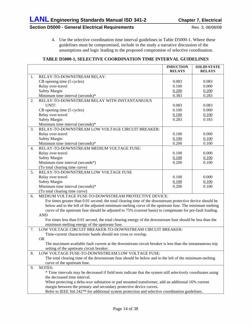
4. Use the selective coordination time interval guidelines in Table D5000-1. Where these guidelines must be compromised, include in the study a narrative discussion of the assumptions and logic leading to the proposed compromise of selective coordination.
TABLE D5000-1, SELECTIVE COORDINATION TIME INTERVAL GUIDELINES
INDUCTION RELAYS
SOLID-STATE RELAYS
1. RELAY-TO-DOWNSTREAM RELAY: CB opening time (5 cycles) Relay over-travel Safety Margin Minimum time interval (seconds)*
0.083 0.100 0.200 0.383
0.083 0.000 0.200 0.283
2. RELAY-TO-DOWNSTREAM RELAY WITH INSTANTANEOUS UNIT:
CB opening time (5 cycles) Relay over-travel Safety Margin Minimum time interval (seconds)*
0.083 0.100 0.100 0.283
0.083 0.000 0.100 0.183
3. RELAY-TO-DOWNSTREAM LOW VOLTAGE CIRCUIT BREAKER: Relay over-travel Safety Margin Minimum time interval (seconds)*
0.100 0.100 0.200
0.000 0.100 0.100
4. RELAY-TO-DOWNSTREAM MEDIUM VOLTAGE FUSE: Relay over-travel Safety Margin Minimum time interval (seconds*) (To total clearing time curve)
0.100 0.100 0.200
0.000 0.100 0.100
5. RELAY-TO-DOWNSTREAM LOW VOLTAGE FUSE Relay over-travel Safety Margin Minimum time interval (seconds)* (To total clearing time curve)
0.100 0.100 0.200
0.000 0.100 0.100
6. MEDIUM VOLTAGE FUSE-TO-DOWNSTREAM PROTECTIVE DEVICE: For times greater than 0.01 second, the total clearing time of the downstream protective device should be below and to the left of the adjusted minimum-melting curve of the upstream fuse. The minimum melting curve of the upstream fuse should be adjusted to 75% (current basis) to compensate for pre-fault loading.
AND For times less than 0.01 second, the total clearing energy of the downstream fuse should be less than the minimum melting energy of the upstream fuse.
7. LOW VOLTAGE CIRCUIT BREAKER-TO-DOWNSTREAM CIRCUIT BREAKER: Time-current characteristic bands should not cross or overlap.
OR The maximum available fault current at the downstream circuit breaker is less than the instantaneous trip setting of the upstream circuit breaker.
8. LOW VOLTAGE FUSE-TO-DOWNSTREAM LOW VOLTAGE FUSE: The total clearing time of the downstream fuse should be below and to the left of the minimum-melting curve of the upstream fuse.
9. NOTES: * Time intervals may be decreased if field tests indicate that the system still selectively coordinates using the decreased time interval. When protecting a delta-wye substation or pad mounted transformer, add an additional 16% current margin between the primary and secondary protective device curves. Refer to IEEE Std 242™ for additional system protection and selective coordination guidelines.
Page 14 of 38
LANL Engineering Standards Manual ISD 341-2 Chapter 7, Electrical Section D5000 - General Electrical Requirements Rev. 3, 06/06/08
5. Provide tabulated circuit breaker electronic trip unit settings based on the results of the fault current study and the coordination study; include the following information for each circuit breaker electronic trip unit: • Circuit number • Load name • Sensor rating (amperes) “S” • Rating plug (amperes) “P” • Long time pickup setting (times P) • Long time delay setting (seconds) • Short time pickup setting, if used (times P) • Short time delay setting, if used (seconds) • Instantaneous pickup setting (times P) • Ground fault pickup setting (times P) • Ground fault delay setting (seconds) • Trip unit manufacturer and model • Remarks (i.e. i2t setting, etc.)
E. Perform arc-flash hazard analysis using procedures outlined in IEEE Std 1584a™.18 Commercial software may be used if it has been benchmark tested and provides results that are consistent with results from using the IEEE® procedures12. Perform arc-flash hazard calculations for switchgear, switchboards, transformers, motor control centers, panelboards, motor controllers, safety switches, and industrial control panels. Base calculations on the installed equipment and components; coordinate with the power system studies required in LANL Master Specification Section 26 0813, Electrical Acceptance Testing. Tabulate the following calculated information for each location:
1. Voltage
2. Short-circuit current
3. Arcing current
4. Overcurrent protective device clearing time at the arcing current
5. Arc Flash Hazard Boundary
6. Arc flash incident energy in cal/cm2
7. Working distance19 selected from IEEE Std 1584™ based on the equipment type
8. Hazard/risk category number from NFPA 70E Table 137(C)(9) for operations with doors closed and covers on.20
Note: Equipment below 240 volts need not be considered an arc flash hazard unless it involves at least one 125 kVA or larger low-impedance transformer in its immediate power supply.21
18 LANL ISD 101-13, Electrical Safety Program, IEEE Std 1584a™ as the preferred method for calculating the Flash Hazard Boundary and the Arc-Flash Incident Energy. 19 Working distance is the distance for the head and torso from energized parts; it is a function of the type of equipment and the system voltage. 20 This requirement recognizes the non-zero possibility of an arc-flash event even with equipment doors closed; refer to NFPA pre-print of the 2008 edition of NFPA 70E , section 110.8(A). 21 Refer to IEEE Std 1584a §4.2.
Page 15 of 38
LANL Engineering Standards Manual ISD 341-2 Chapter 7, Electrical Section D5000 - General Electrical Requirements Rev. 3, 06/06/08
F. Provide documented analysis (e.g. life cycle cost analysis or spend limit analysis) to support each recommendation to modify, refurbish, repair, or otherwise retain – as opposed to replace – an existing major electrical equipment item (e.g. switchgear, switchboard, UPS, engine-generator, motor control center) that has been in service for more than 15 years22. Compare the alternatives over the duration of the remaining service life of the facility, assuming a discount rate of 5 percent. Include consideration of the following factors:
1. Age and condition of the existing equipment.23
2. Extent of the proposed modification and the availability of proper parts for the modifications.24
3. Availability of qualified personnel to perform the proposed modifications to the existing equipment.24
4. Remaining service life of the existing equipment and of the facility.25
5. Estimated cost of facility downtime for proposed modification vs. facility downtime for replacement.26
6. Estimated cost for proposed modification vs. cost for replacement with modern equipment.27
7. Improvements in factors such as safety, efficiency, reliability, and maintainability afforded by modern replacement equipment compared to modified existing equipment.
Note: Address all cases where existing equipment has inadequate ratings28 for the intended application to the LANL Electrical AHJ.
G. Refer to other system elements (e.g. lighting, grounding, etc.) for additional electrical calculation requirements pertaining to those system elements.
4.3 Drawings
A. Provide a complete drawing package as required to meet project specific requirements.
B. New drawings for a Design Change Package29 (DCP) or an Engineering Change Notice30 (ECN), and all new construction design packages shall meet the requirements below.
C. Comply with the LANL Drafting Manual for composition, organization, and format of drawings in a design package.
22 Refer to ESM Chapter 1 Section Z10 paragraph 9.0; the expected service life for electrical equipment is set at 20 years for decision analysis. This requirement for analysis starts at 75% of the expected service life for the purpose of identifying old equipment that may 23 Refer to IEEE Std 141 §2.5-i. 24 Refer to IEEE Std 902 §9.6. 25 Refer to ESM Chapter 1 Section Z10 paragraph 9.0. 26 Refer to NFPA 70B §4-3. 27 Refer to IEEE Std 141 Chapter 16. 28 Refer to NFPA 70B §4-4.3. 29 Refer to LANL AP-341-505. 30 Refer to LANL AP-341-506.
Page 16 of 38
LANL Engineering Standards Manual ISD 341-2 Chapter 7, Electrical Section D5000 - General Electrical Requirements Rev. 3, 06/06/08
D. Demolition: Provide drawings indicating electrical demolition required for the project. Clearly indicate what is to be removed, what is to remain in service, locations to disconnect electrical energy sources, and organizations with which the Subcontractor must coordinate demolition work. CAUTION: Subcontractor remains responsible for verifying adequacy/safety of demolition design via hazard analysis/work control (e.g., IWD) and lockout/tagout programs.31
E. Use Electrical Drawing ST-D5000-1 for electrical symbols. Delete the general notes on projects that have construction specifications.
F. Provide plan drawings as required to show the location of electrical service and distribution equipment, luminaires, lighting control devices, receptacle outlets, equipment connections, branch circuiting, telecommunications outlets and distribution, paging system components, lightning protection system, grounding electrode system, and other system components as required by project.
G. Use Electrical Drawing ST-D5000-2 as a template for the project electrical one-line diagram. Edit the template to meet project specific requirements. Use additional sheets as required for large systems.
1. A one-line diagram as described in this section shall be used to represent the electrical power service and distribution system for each facility. The one-line shall show the electrical distribution system from the service point down to the lighting/power panelboard and motor control center level.
2. One-line diagram size, drafting layers and software shall be in accordance with the LANL Drafting Manual. One-Line diagrams shall be formatted as depicted in LANL Standard Drawing ST-D5000-2.
3. The one-line diagram shall be configured such that upstream to downstream paths are shown from top to bottom or left to right.
4. One-line diagram symbols shall be in accordance with the LANL Drafting Manual and the standard legend and symbols provided in LANL Standard Drawing ST-D5000-1.
5. LANL Standard Drawing ST-D5000-1 and ST-D5000-2 shall be followed for the consistent layout and application of symbols.
6. Any equipment to be included in a one-line that is not reflected in the LANL standard drawings shall be depicted in accordance with IEEE Std 315.
7. One-line diagrams shall include the following information as applicable:
• Utility source(s): Utility circuit voltage, circuit number(s), riser pole number(s), pad-mounted switchgear cubicle number(s), and manhole structure number(s).
• Supply characteristics: Service point nominal system voltages (e.g. 480Y/277 V, 208Y/120V, 120/240 V), system configurations (wye or delta, grounded or ungrounded), frequency (if other than 60 Hz), phase rotation (if other than NEC® standard), and short-circuit current (3-phase, RMS symmetrical amperes).
31 Lessons learned from LANL SM-1321/287 Syllac Building demolition 13.2 kV near miss (ALO-LA-LANL-WASTEMGT-2003-0006).
Page 17 of 38
LANL Engineering Standards Manual ISD 341-2 Chapter 7, Electrical Section D5000 - General Electrical Requirements Rev. 3, 06/06/08
• Power transformers: Ratings (kVA, primary voltage, secondary voltage, and percent impedance), cooling methods (e.g. OA/FA), winding connections, grounding electrode conductor size, dielectric type, location.
• Generator systems: Ratings (voltage, subtransient reactance, kW/kVA at sea level and at 7500 ft), connection, fuel type, transfer switch ratings, equipment code, and location.
• Major distribution equipment (e.g. unit substations, switchgear, switchboards, panelboards): Equipment code, location (room number), ratings (system voltage, frequency if other than 60 Hz, amperes, connection type), short-circuit current (3- phase, RMS symmetrical amperes), short-circuit interrupting rating, types of loads served, electrical and/or mechanical interlocks between devices.
• Service and feeder switching and overcurrent protective devices: Circuit number, number of poles (if other than three poles), switch or circuit breaker frame size in amperes, circuit breaker long-time trip amperes, circuit breaker ground-fault trip amperes, fuse rating and type, short-circuit interrupting rating. Provide same information for branch circuits shown on the one-line diagram.
• Protective relays: Function, use, type, and number. Use device function numbers from IEEE C37.2™.
• Services and feeders: Raceway size and length. Quantity, size, type (if other than copper), and insulation type for phase, grounded, and equipment grounding conductors. Provide the same information for branch circuits that are shown on the one-line diagram.
• Metering: Voltmeters, ammeters, kW/kWh meters, test blocks, electronic metering packages.
• Potential transformers: Number, ratio, and overcurrent protection
• Current transformers: Number and ratio.
• Dry-type transformers: Ratings (kVA, K-factor, primary voltage, secondary voltage, and percent impedance), cooling methods (e.g. OA/FA), temperature rise, winding connections, location, grounding electrode conductor size.
• Surge protective devices: Indicate surge protective devices for medium-voltage equipment, low-voltage service equipment, and specialized systems (e.g. isolated ground power systems).
• Uninterruptible Power Supply (UPS) Systems: Equipment code, location (room number), ratings (input and output voltage, frequency if other than 60 Hz, amperes, connection type), static and manual bypass arrangements, battery run-time, types of loads served, short-circuit current (3-phase, RMS symmetrical amperes).
• Major loads:32 Voltage, kVA rating, and location of branch circuit loads rated 100 amperes and greater and all loads connected to switchboards or switchgear assemblies.
• Motors: Voltage, horsepower or kVA rating, starting method if other than across the line, interlocks between controllers, and location of all motors connected to
32 The one-line diagram is generally not intended to show branch circuits; however, information about major loads and large branch circuits increases the usefulness of the diagram.
Page 18 of 38
LANL Engineering Standards Manual ISD 341-2 Chapter 7, Electrical Section D5000 - General Electrical Requirements Rev. 3, 06/06/08
switchgear and switchboards. Motors connected to motor control centers or panelboards are branch circuit loads; they can be shown either on one-line diagrams or included in schedules; consult with the Facility Manager or the User for preference.
• Available short-circuit current: The calculated three-phase bolted short-circuit current at each bus down to points in the distribution system where fault duty is less than 14,000 amps RMS symmetrical on 480Y/277V systems and less than 10,000 amps RMS symmetrical on 208Y/120V or 240/120V systems.
• Critical systems: Indicate critical loads (e.g. safety class or safety significant, emergency power systems, standby power systems).
• Battery systems: Equipment code, location (room number), battery and charger ratings (input and output voltage, amperes, connection type), bypass arrangements, battery run-time, types of loads served, short-circuit current.
• Service Load Summary: Provide a summary of the calculated or measured load for the service entrance. Refer to Drawing ST-D5000-2 for the required content and format.
• Engine-Generator Load Summary: Provide a summary of the calculated or measured loads for the engine-generator system(s). Indicate the NEC 110 Level, Type, and Class. Indicate the system configuration (e.g. single unit, N+1).
• UPS Load Summary: Provide a summary of the calculated or measured loads for the UPS system(s) Indicate the NEC 111 Level, Type, and Class. Indicate the system configuration (e.g. single unit, parallel-redundant, N+1 battery).
H. Use Electrical Drawing ST-D5010-1 as a template for the project grounding diagram. Edit the template to meet project specific requirements.
I. Use Electrical Drawing ST-D5010-2 as a template for the project isolated ground system diagram(s) (if present). Edit the template to meet project specific requirements.
J. Use Electrical Drawing ST-D5030-1 as a template for the project telecommunications system riser diagram(s) and telecommunications room plan(s). Edit the template to meet project specific requirements.
K. Use Electrical Drawing ST-D5000-3 as a template for the project circuit designations and electrical equipment identification. Edit the template to meet project specific requirements.
L. Use Electrical Drawing ST-D5020-1 as a template for the project motor control diagrams. Edit the template to meet project specific requirements. One control diagram may be used to represent more than one identical motor control connection.
4.4 Construction Specifications
A. Provide a complete specification package as required to meet project specific requirements.
B. Specification set composition, organization, and format shall comply with the LANL Master Specification Manual.
Page 19 of 38
LANL Engineering Standards Manual ISD 341-2 Chapter 7, Electrical Section D5000 - General Electrical Requirements Rev. 3, 06/06/08
C. Edit the applicable LANL Master Specification sections to meet project specific requirements: refer to paragraph 2.3-B of this Section.
D. Generate additional construction specification sections as required to describe project materials or systems not addressed in the LANL Master Specification sections.
E. Refer to ESM Chapter 1 Section Z10 for requirements concerning project construction specifications.
4.5 Sealing Construction Documents
Refer to ESM Chapter 1 Section Z10.
5.0 SYSTEM REQUIREMENTS
5.1 Adequacy and Future Expansion
A. Provide electrical systems with adequate capacity for the initial known requirements plus provisions for future expansion of the system as follows:
1. For new facilities, provide for load growth of 1 percent of the initial design load per year of expected facility service life33, but not exceeding 30 percent. For new facilities with less than 20 years expected service life, less than 20 percent future load growth capability may be used with written authorization from the Chapter 7 P.O.C.
2. For service renovations to existing facilities, provide for 1 percent per year load growth based on the expected remaining service life of the renovated facility.
B. Refer to paragraph 9.0, Design Goals, in Section Z10 of ESM Chapter 1 for expected lives of systems and structures.
5.2 Sustainable Design and Energy Conservation
A. Comply with ESM Chapter 14, Sustainable Design.
B. Refer to ASHRAE/IESNA Standard 90.1 for interior lighting power budgets, exterior lighting power budgets, power distribution requirements, and motor efficiency requirements.
5.3 Fault Current Capacity
Provide electrical equipment with bus bracing and device interrupting capacities that exceed the fault current available at the terminals.
5.4 Lightning
Provide systems protected from the effects of direct or nearby lightning discharges in accordance with NFPA 780, IEEE Std 1100, and the IEEE C62 Surge Protection Standards Collection. In an
33 Refer to IEEE Std. 141-1993, paragraph 2.4.1.4.
Page 20 of 38
LANL Engineering Standards Manual ISD 341-2 Chapter 7, Electrical Section D5000 - General Electrical Requirements Rev. 3, 06/06/08
average year Los Alamos experiences 61 thunderstorm days a year, about twice the national average.34 The lightning flash density for parts of LANL is 8 flashes to ground per sq km per year 35. Refer to Section D5090.
5.5 Operating Altitude
Provide electrical equipment that is suitable and rated (or properly de-rated) for operation at an elevation of not less than 7500 feet.36 The reduced air pressure at this elevation impedes equipment cooling and reduces the electrical insulation properties of air. 37 NOTE: Some LANL facilities such as TA-16, TA-28, and TA-57 (Fenton Hill) are at elevations higher than 7500 feet; provide equipment suitable for use at the elevation of such sites; see ESM Chapter 1 Section Z10.
5.6 Power Quality
A. Provide electrical systems that are selected and configured to provide adequate power quality for the satisfactory operation of electrical utilization equipment:
1. The highest practical service, distribution, and utilization voltages should be used.
2. High-impact electrical loads such as HVAC equipment, elevators, and process loads should be segregated on separate feeders from sensitive loads.
3. Step-down transformers and associated panelboards should be located physically close to the loads that they serve.
4. Loads on each feeder should be balanced so the voltage on each phase will be within 1 percent of the average voltage of the three phases.38
B. Follow recommended practice in IEEE Std 1100™ and IEEE Std 141™.
5.7 Power System Harmonic Limits
Limit harmonic currents at the point of service for each building to comply with IEEE Std 519™.39
34 Climatology information (average temperatures, thunderstorm frequency, etc.) is from “Brief Climatology for Los Alamos, NM” available at http://weather.lanl.gov. (A thunderstorm day is defined as a day on which thunder is heard or a thunderstorm occurs.) 35 Lightning flash density map for Los Alamos from Global Atmospherics, Inc. for 1/1/2001 to 12/31/2001. 36 Altitude at LANL ranges from 6250 ft at TA-39 to 7780 ft at TA-16. Elevation information is from USGS 1:24000 quadrant maps: Frijoles, NM and White Rock, NM. 37 IEEE Std 1015™, “Recommended Practice for Applying Low-Voltage Circuit Breakers Used in Industrial and Commercial Power Systems,” the ANSI C37 collection “Circuit Breakers, Switchgear, Substations, and Fuses,” and the ANSI C57 collection “Distribution, Power, and Regulating Transformers” provide information about the de-rating effects of elevation on electrical equipment. 38 DOE Office of Industrial Technologies Motor Tip Sheet #7, September 2005 available at http://www1.eere.energy.gov/industry/bestpractices/pdfs/eliminate_voltage_unbalanced_motor_systemts7.pdf 39 IEEE Std. 141-1993™, Chapter 9 points to IEEE Std 519 for limits on the harmonic currents that a user can induce back into the utility power system.
Page 21 of 38
LANL Engineering Standards Manual ISD 341-2 Chapter 7, Electrical Section D5000 - General Electrical Requirements Rev. 3, 06/06/08
5.8 Power System Reliability
Power system reliability consideration shall comply with IEEE 493™ to ensure continual power supply to systems and equipment designated by project design criteria as “mission critical,” “safety significant,” or “safety class.” Consider the need for multiple transformer-switchgear service equipment to ensure power supply continuity within the facility during scheduled or emergency equipment outages.40
5.9 Selective Coordination
A. Provide selectively coordinated overcurrent protection; refer to the Calculations paragraph in this Section for detailed requirements.
B. When the NEC® requires ground-fault protection for service or feeder disconnecting means, provide an additional step of ground fault protection in the next level of feeders as required to provide fully selectively coordinated ground-fault protection.
5.10 Standards for Material and Equipment
A. Use electrical materials and equipment that is constructed and tested in accordance with the standards of NEMA, ANSI, ASTM, or other recognized commercial standard.
B. If material and equipment is labeled, listed, or recognized by any Nationally Recognized Testing Laboratory (NRTL) acceptable to OSHA and the LANL Electrical AHJ, then provide NRTL labeled, listed, or recognized material and equipment.41 Acceptable Nationally Recognized Testing Laboratories include42:
• Underwriters Laboratories, Inc. (UL) • Factory Mutual Research Corp. (FMRC) • Intertek Testing Services NA, Inc. (ITSNA, formerly ETL) • Canadian Standards Association (CSA)
A complete listing of acceptable NRTLs is located at http://www.osha.gov/dts/otpca/nrtl/
C. Where material and equipment is not labeled, listed, or recognized by any NRTL, provide a manufacturer’s Certificate of Compliance indicating complete compliance of each item with applicable standards of NEMA, ANSI, ASTM, or other recognized commercial standard.
D. Do not install or use electrical material or equipment for any use other than that for which it was designed, labeled, listed, or identified unless formally approved for such use by the LANL Electrical AHJ.43
40 IEEE 493™ provides methods for quantitative reliability analysis as it applies to the planning and design of electric power distribution systems. 41 LANL ISD 101-13, “Electrical Safety;” OSHA 1910.303(a); OSHA 1926.403(a); and NEC® Article 110.2 establish the requirement that electrical system and utilization equipment be acceptable to the AHJ. 42 LANL ISD 101-13,, “Electrical Safety” establishes that NRTLs acceptable to the LANL AHJ are those “Organizations Currently Recognized by OSHA as NRTLs” on the OSHA website. 43 This National Electrical Code® requirement is re-stated for emphasis.
Page 22 of 38
LANL Engineering Standards Manual ISD 341-2 Chapter 7, Electrical Section D5000 - General Electrical Requirements Rev. 3, 06/06/08
5.11 Personnel Safety
A. Design systems and select equipment to reduce electrocution, arc flash, and arc blast hazards to maintenance and operations personnel.44
B. Equipment and design practices are available to minimize energy levels and the number of at-risk procedures that require an employee to be exposed to high energy level sources. Proven designs to reduce the hazards of electrical systems include:
1. Arc-resistant medium-voltage switchgear,
2. Remote racking (insertion or removal) of circuit breakers,
3. Remote opening and closing of switching devices,
4. Current limitation obtained with higher impedance transformers or current-limiting reactors, and
5. Insulated or isolated bus in switchboards and switchgear assemblies.
6.0 EQUIPMENT LOCATION
6.1 General
A. Locate electrical equipment so it will be accessible for inspection, service, repair, and replacement without removing permanent construction, with working clearance and dedicated space as required by the NEC® and as recommended by the manufacturer.45
B. Locate equipment so generator exhaust, etc. does not enter occupied spaces through outside air intakes.
C. Select sites carefully when locating equipment outside on grade. Ensure that factors such as snow accumulation, ice, windy areas, rainwater from roof overhangs, etc., do not affect equipment performance and maintenance. Avoid locations on the north side of the building.
D. Locate equipment to minimize noise and sound vibration transmission to occupied areas of the building.
E. Locate roof-mounted electrical equipment a minimum of 10 feet from the edge of roof or inside face of parapet. If the distance is less than 10 feet, specify a 42-inch-high restraint, e.g., guard rails, parapet, screen wall, etc.46
44 Refer to NFPA 70E, Article 130.1. 45 NEC® Article 110 establishes minimum working clearances and dedicated spaces for electrical equipment 46 29 CFR 1926.501(b)(1) requires fall protection when the working distance from the equipment is 6 feet or less; 10 feet minimum distance allows for equipment door swings and removal of equipment.
Page 23 of 38
LANL Engineering Standards Manual ISD 341-2 Chapter 7, Electrical Section D5000 - General Electrical Requirements Rev. 3, 06/06/08
6.2 Equipment Rooms and Spaces
A. Provide one or more dedicated electrical equipment rooms or dedicated electrical equipment spaces on each floor in every building except for modifications where loads can be served from existing equipment.47
1. Provide electrical equipment rooms to house switchgear, switchboards, power panelboards, transformers, transfer switches, lighting control relay panels, and similar distribution equipment in office buildings or light laboratory buildings.
2. Dedicated electrical equipment spaces may be used in lieu of equipment rooms for switchgear, panelboards, transformers, transfer switches, lighting control relay panels, and similar distribution equipment in industrial, process, or production buildings.
3. In laboratory buildings, one or more panelboards dedicated to each laboratory may be located in the corridor outside the lab entrance door. Recess lab panelboards in public corridors. Lab panelboards may be surface mounted in non-public service corridors.
4. In existing buildings where no other suitable location is available, and with the consent of the LANL Electrical Authority Having Jurisdiction, panelboards may be recess mounted in corridors.
B. Design electrical equipment rooms or spaces to facilitate equipment installation/removal and to provide adequate access for operation and maintenance of the equipment.
C. Make provisions for the removal of the largest component from each electrical room or space for off-site servicing. Provide adequate floor loading capability on the access routes and in the electric rooms or spaces for the electrical equipment and material handling equipment.48
D. Locate electrical rooms or spaces in the building to satisfy the following criteria:
1. Maximum feeder voltage drop: 2 percent49
2. Maximum branch circuit voltage drop: 3 percent49
3. Maximum 208Y/120V system branch circuit length: 100 ft 50
4. Maximum 480Y/277V system branch circuit length: 230 ft 51
5. Electric rooms or spaces vertically aligned in multi-story buildings.52
6. Branch circuit panelboards on the same floor as the loads they serve.53
47 Dedicated electrical rooms make it more likely that LANL will remain in compliance with the following NEC® Sections: 110.11, 110.13(b), 110.26, 110.27, 110.30, 110.31, 110.32, 110.33, and 110.34. 48 Refer to Clause 1.15 in IEEE Std 241-1990™ for additional building access and loading information. 49 Voltage drop criteria are mandatory provisions in ASHRAE/IESNA Standard 90.1-1999. 50 100 ft is the approximate maximum circuit length serving a 120V 16-ampere, 0.95 pf line-neutral load through a magnetic conduit with 12 AWG conductors in a balanced multi-wire circuit or with 10 AWG conductors in a 2-wire circuit with 3% voltage drop. 51 230 ft is the approximate maximum circuit length serving a 277V 16-ampere, 0.95 pf line-neutral load through a magnetic conduit with 12 AWG conductors in a balanced multi-wire circuit or with 10 AWG conductors in a 2-wire circuit with 3% voltage drop. 52 Vertical alignment facilitates installing economical feeders, sharing grounding electrode bars, transformers, etc.
Page 24 of 38
LANL Engineering Standards Manual ISD 341-2 Chapter 7, Electrical Section D5000 - General Electrical Requirements Rev. 3, 06/06/08
E. For indoor installations provide at least 60 inches of clear height to the underside of the building structure above medium-voltage switchgear to allow for vertical conduit elbows above the equipment.54 For indoor installations provide at least 48 inches of clear height to the underside of the building structure above low-voltage switchgear and switchboards to allow for busway transitions and conduit bends above the equipment.55
F. For indoor installations of medium-voltage switchgear, provide access aisles at least 5’-0” in front, 5’-0” in rear (if rear access is required)56, and 3'-0” at ends of equipment after providing space for future expansion.57 For indoor installations of low-voltage, drawout switchgear assemblies, provide access aisles at least 4'-6” in front58, 3’-6” in rear59, and 3'-0”at ends of low-voltage equipment after providing space for future expansion. Provide greataccess space if recommended by the manufacturer or if required to fully open access d
er
oors.
G. For new construction, provide dedicated electrical space equal to width and depth of the equipment extending from floor to a height of 25 ft or to the bottom of the floor slab or roof slab above; allow no piping, ducts, or equipment foreign to the electrical installation in this zone. For work in existing structures, follow Article 110 in the NEC®. 60
H. Provide at least 30 footcandles61 general illumination on the vertical surfaces of the electrical equipment. Provide similar illumination at the rear of freestanding equipment. Provide emergency illumination to avoid safety problems and to facilitate trouble-shooting during a power outage.62
I. Provide at least one general-purpose receptacle in each electric room or space for power tools and supplemental lighting.63
J. Provide HVAC for electrical distribution equipment spaces with 30 percent air filtration and heating/cooling as required to maintain an average ambient temperature not to exceed 86ºF
53 Having the panelboard on the same floor as the load reduces the number of customers disturbed when a panel must be de-energized for maintenance or modification. 54 60” vertical clearance above medium-voltage switchgear allows for the 51” offset of a 6” conduit elbow with 36” radius plus space for conduit hangers. 55 The 48 inch clearance is calculated as follows: 5000A busway switchgear flanged end 10”, transition elbow 21”, edgewise busway centerline to top 13”, busway hanger and support rod 4”. This guidance is from lessons learned from several LANL installations that were very difficult due to inadequate vertical clearance above switchgear. 56 Minimum clear distance based on NEC® Table 110.34(A) using 7960 volts to ground (13,800 / 1.732) and Condition 2. Working space to allow thermographic examination with equipment energized. 57 Based on medium-voltage switchgear manufacturers’ recommendations. 58 Based on switchgear manufacturer’s recommendations based on removal/insertion of draw-out circuit breakers using a top-mounted breaker hoist. 59 Working space to allow thermographic examination with equipment energized. Minimum clear distance based on NEC® Table 110.26(A)(1) using 151-600 volts to ground and Condition 2. 60 To enhance flexibility and expandability, the pre-1999 NEC® dedicated space requirements for electrical equipment are retained for new LANL facilities. In existing facilities that are being renovated, the minimum current NEC® dedicated space requirements are allowed. 61 Lighting Design Guide in Chapter 10 of the Ninth Edition of the IESNA Lighting Handbook recommends 30 footcandles illuminance for industrial maintenance operations. 62 Refer to maintenance illumination recommendations in clause 9.2.3 of IEEE Std 902-1996. 63 NEC® Article 210.50(B).
Page 25 of 38
LANL Engineering Standards Manual ISD 341-2 Chapter 7, Electrical Section D5000 - General Electrical Requirements Rev. 3, 06/06/08
(30ºC). The average ambient temperature shall cover 24 hours, and the maximum temperature during the 24-hour period shall not exceed 104ºF (40ºC).64
K. If possible, locate electrical service equipment in above-grade areas not subject to flooding. If service switchgear must be installed below grade, provide redundant sump pumps supplied from a reliable standby power system.65 Events that could cause flooding include the rupture of fire sprinkler pipe, HVAC pipe, etc.
L. Locate electrical service entrance equipment as close as practical to the building water service entrance and to major electrical loads.
M. Avoid installing panelboards, transformers, etc. in corridors, stairways, or janitor closets.
7.0 ELECTRICAL IDENTIFICATION
7.1 General
A. Comply with LANL Master Specifications Section 26 0553, Identification for Electrical Systems, for electrical identification products, materials, and installation.
B. Refer to Electrical Drawing ST-D5000-3 for preferred locations of electrical identification.
C. Provide schedules in Construction Documents indicating all required information for the following:
1. Arc-flash and shock hazard-warning labels
2. Component identification tags
3. Equipment nameplates
7.2 Arc-Flash and Shock Hazard Warning Labels
A. Install arc-flash and shock hazard-warning labels that comply with ANSI Z535.4 on switchgear, switchboards, transformers, motor control centers, panelboards, motor controllers, safety switches, and industrial control panels.66
B. Provide the following information on each label; for design projects include the information in a schedule on the Drawings or specify that information will be provided as one of the power system studies required in LANL Master Specifications Section 26 0813, Electrical Acceptance Testing:
1. Arc-Flash Protection Boundary67 calculated in accordance with IEEE Std 1584a™.
2. Arc-flash incident energy68 calculated in accordance with IEEE Std 1584a™.
64 Electrical room temperature limits from IEEE C57.12.00, IEEE C57.12.01, IEEE C37.20.1, and IEEE C37.20.3. 65 Recommended practice from Chapter 3 of NECA 400-1998, adapted to medium-voltage equipment. 66 Refer to Section 110.16 in the NEC®. 67 LANL ISD 101-13, Electrical Safety Program, paragraph 4.4.3 identifies IEEE Std 1584a™ as the preferred method for calculating the Flash Hazard Boundary.
Page 26 of 38
LANL Engineering Standards Manual ISD 341-2 Chapter 7, Electrical Section D5000 - General Electrical Requirements Rev. 3, 06/06/08
3. Working distance69 selected from IEEE Std 1584a™ or NFPA 70E based on the equipment.
4. Hazard/risk category number from NFPA 70E Table 137(C)(9) for operations with doors closed and covers on.70
5. System phase-to-phase voltage
6. Condition(s) when a shock hazard exists: e.g. “With door open.”
7. Limited Approach Boundary: as determined from NFPA 70E, Table 130.2(C).
8. Restricted Approach Boundary: as determined from NFPA 70E, Table130.2(C).
9. Prohibited Approach Boundary: as determined from NFPA 70E, Table 130.2(C).
10. Equipment identification code: e.g. “03410-EP-LP-1”
11. Class for insulating gloves based on system voltage (e.g. Class 00 for up to 500 volts).
12. Voltage rating for insulated or insulating tools based on system voltage (e.g. 1000 volts).
13. Equipment ID code based on Drawings and including TA number, building number, and system identifier.
14. Date that hazard analysis was performed.
15. “Served from” circuit directory information including the serving equipment ID code, location (e.g. room number), circuit number, and circuit voltage/phases/wires.
16. If applicable, “serves” circuit directory information including the served equipment ID code, location (e.g. room number), circuit number, and circuit voltage/phases/wires.
C. An abbreviated warning label may be used where it has been determined that no dangerous arc-flash hazard exists in accordance with IEEE Std 1584a™, paragraph 9.3.2.
D. Use a “DANGER” label where the calculated arc-flash incident energy exceeds 40 cal/cm2.
7.3 Component Identification
Identify electrical equipment on drawings and tags in accordance with ESM Chapter 1, Section 200 – Equipment & Component Numbering and Labeling. 71
7.4 Component Identification Tags
Install electrical component identification tags (formerly called code tags) to identify electrical equipment using the System Designation, Equipment Identification, the Tech Area Number, and the Building Number.72
68 LANL ISD 101-13, Electrical Safety Program, paragraph 6.4.3 identifies IEEE Std 1584a™ as the preferred method for calculating the arc-flash incident energy. 69 Working distance is the distance for the head and torso from energized parts; it is a function of the type of equipment and the system voltage. 70 This requirement recognizes the non-zero possibility of an arc-flash event even with equipment doors closed; refer to NFPA 70E, section 110.8(A). 71 ISD 101-19, Safety Signs, Labels, and Tags; NEC® Articles 110.21 and 110. 22. 72 The component identification tag uniquely identifies the equipment item.
Page 27 of 38
LANL Engineering Standards Manual ISD 341-2 Chapter 7, Electrical Section D5000 - General Electrical Requirements Rev. 3, 06/06/08
7.5 Diagrams and Operating Instructions
Post and maintain diagrams, operating instructions and emergency procedures for electrical systems and major equipment. They should consist of simplified instructions and diagrams of equipment, controls and operation of systems, including selector switches, main-tie-main transfers, ATS-bypass, UPS-bypass etc. Post and maintain an up-to-date one-line diagram of the electrical system adjacent to the service entrance equipment.73
7.6 Emergency System Identification
Install markers to identify emergency system transfer switches, generators, switchgear, transformers, motor control centers, panelboards, starters, safety switches, pull boxes, and cabinets as components of the emergency system.74
7.7 Equipment Nameplates
Install electrical equipment nameplates of the following three categories:
1. Category I - Circuit Directory Information: Nameplates shall contain circuit number, piece of equipment being served or being served from, location of equipment served or being served from, voltage, number of phases, and number of wires.75 These nameplates may be omitted from equipment which receives an arc flash and shock hazard warning label that includes the required circuit directory information.
2. Category II - General or Operational Information: Nameplates shall contain basic instructions or specific operating procedures such as special switching procedures for a load transfer scheme.76
3. Category III - Emergency Operations: Nameplate shall contain information concerning emergency shutdown procedures for room, equipment, and building isolation in event of fire or other emergency.76
7.8 Outlet Labels
Install labels on receptacle outlets and light switches indicating circuit number, panelboard, and voltage.77
7.9 Voltage Markers
Install voltage markers on electrical equipment (e.g. switchgear, transformers, motor control centers, panelboards, starters, safety switches, pull boxes, cabinets).78
73 NFPA 70B-1994, paragraph 4-2.3, Recommended Practice for Electrical Equipment Maintenance, strongly recommends having system diagrams, operating instructions, and emergency procedures readily available. 74 NEC® Section 700.9(A) requires identification of components of an emergency power system. 75 Category I nameplates are essential to the efficient implementation of the LANL lock-out/tag-out program. 76 NFPA 70E Section 205.8 requires safety-related operating or maintenance instructions be posted on equipment. 77 Labeling of outlets and switches to indicate circuit is a long-standing practice at LANL to facilitate maintenance and lock-out/tag-out.
Page 28 of 38
LANL Engineering Standards Manual ISD 341-2 Chapter 7, Electrical Section D5000 - General Electrical Requirements Rev. 3, 06/06/08
7.10 Warning Signs
Install warning signs that conform to ANSI Z535.2 and meet the intent of the OSHA and NEC® danger and caution specifications on electrical equipment containing hazardous voltages (e.g. switchgear, switchboards, transformers, motor control centers, panelboards, starters, safety switches, busways, pull boxes, and cabinets).79
7.11 Wire Markers
Install wire markers on power, control, instrumentation, fire alarm, and communications circuit wires.80
7.12 Working Space Markers
A. In electrical rooms and electrical spaces, permanently mark the floor with the NEC® required clear space in front of and behind switchgear, transformers, motor control centers, panelboards, starters, and safety switches. Install marking on the floor using color schemes conforming to ANSI Z535.1: black and white striped border.
1. Rear clear working space is required for maintenance activities such as thermographic inspection of energized switchgear.81
2. Floor marking may be omitted in carpeted areas and similar areas where floor marking is not practical.
B. Install working space labels on all equipment likely to require examination, adjustment, servicing, or maintenance while energized.
8.0 ELECTRICAL SUPPORTS AND ANCHORAGE A. Install supports and anchorage for electrical equipment in accordance with the NEC®,
manufacturer’s instructions, and ESM Chapter 5, Structural. Use appropriate hangers, supports, anchors, braces, concrete bases, sleeves, inserts, seals, and associated fastenings.
B. Support and anchorage requirements for electrical components are a function of the natural phenomena hazard (NPH) performance category (PC) level that is assigned to that component. The NPH PC level is generally higher for safety class and safety-significant components, however, a higher NPH PC level may be assigned to systems that are mission critical. Consult with the LANL Structural POC and/or Project Leader for support and anchorage requirements.
1. For PC-1 and PC-2 components, the design of supports and anchorage shall generally follow the requirements of the International Building Code, latest edition/supplements.
78 Voltage identification requirement in the New Mexico State Electrical Code for 480-volt equipment is extended to 208 and 240-volt equipment. 79 NEC Section 110.27 requirement for warning signs on entrances to rooms or other guarded locations is extended to include electrical equipment enclosures. 80 Labeling of conductors is a long-standing practice at LANL to facilitate trouble-shooting of systems. 81 Marking of the NEC® required clear space at electrical equipment helps keep facility users from using these areas for storage.
Page 29 of 38
LANL Engineering Standards Manual ISD 341-2 Chapter 7, Electrical Section D5000 - General Electrical Requirements Rev. 3, 06/06/08
2. For PC-3 and PC-4 components, the design of supports and anchorage shall follow the requirements of DOE-STD-1020 and the ESM Structural Chapter Section III.
C. The design values published as manufacturer’s allowable values for anchor bolts and pre-manufactured supports may be used provided that they are set at 98% exceedance values.
D. Refer to the following LANL Master Standards for additional requirements:
1. ESM Chapter 5, Structural.
2. LANL Master Specification Section 13 4800, Sound, Vibration, and Seismic Control. 82
3. LANL Master Specification Section 26 0529, Hangers and Supports for Electrical Systems for materials and installation methods.
4. The heading “Additional Requirements for Safety-Related Systems” in this Section for special requirements and guidance.
9.0 RODENT-PROOFING A. Purchase and install outdoor low-voltage and medium-voltage equipment to be rodent-proof
with maximum 1/4 inch83 unprotected openings in enclosures.
B. Seal all cable entries and plug unused conduits entering outdoor equipment with material that rodents will not be able to gnaw through, squeeze through, or push aside. Suitable materials include 24-gauge or heavier galvanized sheet steel, 19-gauge galvanized woven/welded 1/4” mesh hardware cloth, 16 to 19-gauge stainless steel 1/4” mesh hardware cloth, and galvanized lath screen.84
C. When penetrating an exterior wall, roof, or floor for the passage of conduits, wireways, busducts, etc., seal opening and provide a metal collar securely fastened to the structure.84
D. Seal all cable entries and plug unused conduits entering indoor equipment from outdoors with material that rodents will not be able to gnaw through, squeeze through, or push aside. Suitable materials include 24-gauge or heavier galvanized sheet steel, 19-gauge galvanized woven/welded 1/4” mesh hardware cloth, 16-19-gauge stainless steel 1/4” mesh hardware cloth, and galvanized lath screen. 84
10.0 DEMOLITION A. Remove abandoned electrical distribution equipment, utilization equipment, outlets, and the
accessible portions of wiring, raceway systems, and cables back to the source panelboard,
82 DOE- STD-1020 requires seismic protection based on the assigned PC level. LANL Master Specification 13 4800 provides seismic protection measures for mechanical and electrical equipment. 83 By gnawing, mice can gain entry through openings larger than 1/4 inch. Refer to “Rodent Exclusion Techniques” pamphlet published by the National Park Service in 1997. 84 Refer to “Rodent Exclusion Techniques” pamphlet published by the National Park Service in 1997 available at http://www.nps.gov/public_health/inter/info/general/rpmanual.pdf.
Page 30 of 38
LANL Engineering Standards Manual ISD 341-2 Chapter 7, Electrical Section D5000 - General Electrical Requirements Rev. 3, 06/06/08
switchboard, switchgear, communications closet, or cabinet.85 Abandoned wiring and raceways can result from actions that include the following:
• Equipment is removed or relocated. • Fixtures are removed or relocated. • System is no longer used. • There is no demonstrable near term future use for the existing circuit or raceway system.
Leave abandoned electrical equipment and material in place only if one or more of the following conditions exist: • The system is in a radiological contaminated area and ALARA precludes the removal. • The removal requires the demolition of other structures, finishes, or equipment that is
still in use. An example is abandoned conduit above an existing plaster ceiling. • Removal is not feasible due to hazards, construction methods, or restricted access.
B. Remove conduits, including those above accessible ceilings, to the point that building construction, earth, or paving covers them. Cut conduit beneath or flush with building construction or paving. Plug, cap, or seal the remaining unused conduits. Install blank covers for abandoned boxes and enclosures not removed.86
C. Extend existing equipment connections using materials and methods compatible with the existing electrical installation and this Chapter 7.
D. Restore the original fire rating of floors, walls, and ceilings after electrical demolition.87
E. Use approved lock-out/tag-out procedures to control hazardous energy sources. Assure that an electrically safe work condition exists in the demolition area before beginning demolition.88 Where possible, disconnect the building from all sources of electrical power before beginning demolition; if this is not possible, contact the LANL Electrical AHJ for planning and operational support of electrical safety during demolition.89
11.0 ACCEPTANCE TESTING
11.1 General
A. Perform acceptance testing, inspection, function tests, and calibration to assure that installed electrical systems and components (SSCs), both Subcontractor and user supplied, are:
1. Installed in accordance with design documents and manufacturer’s instructions,
85 LANL institutional policy developed through observation and experience. Removal of abandoned equipment, outlets, wiring, and raceways will have positive safety benefit for maintenance and operations personnel; in addition it will reduce the clutter and obstructions in LANL facilities. 86 LANL institutional policy developed through observation and experience. Describe extent and limits of demolition work. 87 The logic in 2002 NEC® Article 300.21 for preventing the spread of fire and products of combustion is extended from new construction to demolition. 88 ISD 101-13, “Electrical Safety,” applies to D&D work. 89 Refer to LANL AHJ memo dated February 13, 1995, Subject: Electrical Safety in Demolition Work and Remodeling Projects.
Page 31 of 38
LANL Engineering Standards Manual ISD 341-2 Chapter 7, Electrical Section D5000 - General Electrical Requirements Rev. 3, 06/06/08
2. Tested and inspected in accordance with applicable codes and standards (e.g. NFPA 110 and NFPA 111),
3. Ready to be energized, and
4. Operational and within industry and manufacturer’s tolerances.
B. Use the graded approach outlined in Table D5000-2 to determine the degree or formality of acceptance testing that is consistent with the institutional risk of a failure of the particular electrical system or component type balanced against the safety risks associated with performing the acceptance testing, inspection, and calibration.90
1. If the indicated threshold is not exceeded for a particular system or equipment type, then only the Subcontractor-performed inspections and tests described in the specification section for that particular system or equipment type are required.91
2. If the indicated threshold is exceeded for a particular system or equipment type, then that system or equipment type must receive formal electrical acceptance testing and inspections in accordance with LANL Master Specifications Section 26 0813, Electrical Acceptance Testing92 using the current edition of NETA ATS, Acceptance Testing Specification.93
3. For ML-3 systems the Design Authority may invoke formal electrical acceptance testing for selected electrical systems at lower thresholds than indicated in Table D5000-2.
4. If formal electrical acceptance inspection and testing is required for one or more systems or equipment types, then it may be cost-effective to use the Electrical Testing Agency to perform acceptance inspection and testing on all applicable electrical systems.
90 This graded approach for electrical acceptance testing is based on the safety design criteria (using Management Level) and/or operational impact (using component ratings) of electrical system failures, balanced against the cost of performing the tests and the hazards involved. The validity of this graded approach is broadly indicated by comparing IEEE Std 141 to IEEE Std 241: the industrial electric power distribution standard has extensive discussions about electrical acceptance testing in §5.9, but the commercial building power systems standard has no similar discussion. IEEE Std 141 is referenced as a code for both Safety-Class and Safety-Significant (ML-1 and ML-2) electrical systems in DOE G 420.1-1, so all ML-1 and ML-2 systems are indicated to receive formal electrical acceptance testing. Project experience indicates that 800 amperes is an appropriate demarcation between the typical small GPP office buildings and small laboratory facilities such as CINT that have significantly greater operational impact. It is appropriate for electrical systems in larger commercial-type office buildings such as NSSB buildings to receive formal acceptance testing due to the mission impact of the great number of workers that would be affected by an electrical system failure. Medium-voltage electrical systems are indicated to receive formal acceptance testing due to the fact that a system failure would affect a large number of programs and workers. 91 Refer to LANL Master Specifications. 92 LANL Master Specifications Section 26 0813–Electrical Acceptance Testing indicates minimum qualifications for Electrical Testing Agencies and test technicians using a Management Level based graded approach. 93 The NETA Acceptance Testing Specifications (ATS) is a document to assist in specifying required tests on newly-installed electrical power systems and apparatus, before energizing, to ensure that the installation and equipment comply with specifications and intended use as well as with regulatory and safety requirements. The Acceptance Specifications include topics such as Applicable Codes, Standards, and Reference; Qualifications of the Testing Agency; Division of Responsibility; General Information concerning Testing Equipment; Short-Circuit Analysis and Coordinating Studies, System Function Tests; and Thermographic Surveys. The ATS includes tests to be performed on Switchgear and Switchboard Assemblies, Transformers, Cables, Metal-Enclosed Busways, Switches, Circuit Breakers, Network Protectors, Protective Relays, Instrument Transformers, Metering and Instrumentation, Grounding Systems, Ground Fault Systems, Rotating Machinery, Motor Control, Direct-Current Systems, Surge Arresters, Capacitors, Outdoor Bus Structures, Emergency Systems, Automatic Circuit Reclosers and Line Sectionalizers, Fiber-Optic Cables, and Electrical Safety Equipment.
Page 32 of 38
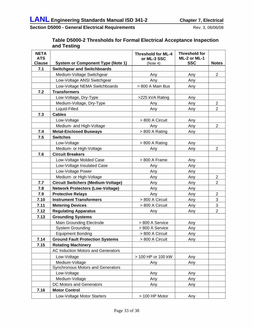
LANL Engineering Standards Manual ISD 341-2 Chapter 7, Electrical Section D5000 - General Electrical Requirements Rev. 3, 06/06/08
Table D5000-2 Thresholds for Formal Electrical Acceptance Inspection and Testing
NETA ATS
Clause System or Component Type (Note 1)
Threshold for ML-4 or ML-3 SSC
(Note 4)
Threshold for ML-2 or ML-1
SSC Notes 7.1 Switchgear and Switchboards
Medium-Voltage Switchgear Any Any 2 Low-Voltage ANSI Switchgear Any Any Low-Voltage NEMA Switchboards > 800 A Main Bus Any
7.2 Transformers Low-Voltage, Dry-Type >225 kVA Rating Any Medium-Voltage, Dry-Type Any Any 2 Liquid-Filled Any Any 2
7.3 Cables Low-Voltage > 800 A Circuit Any Medium- and High-Voltage Any Any 2
7.4 Metal-Enclosed Busways > 800 A Rating Any 7.5 Switches
Low-Voltage > 800 A Rating Any Medium- or High-Voltage Any Any 2
7.6 Circuit Breakers Low-Voltage Molded Case > 800 A Frame Any Low-Voltage Insulated Case Any Any Low-Voltage Power Any Any Medium- or High-Voltage Any Any 2
7.7 Circuit Switchers (Medium-Voltage) Any Any 2 7.8 Network Protectors (Low-Voltage) Any Any 7.9 Protective Relays Any Any 2 7.10 Instrument Transformers > 800 A Circuit Any 3 7.11 Metering Devices > 800 A Circuit Any 3 7.12 Regulating Apparatus Any Any 2 7.13 Grounding Systems
Main Grounding Electrode > 800 A Service Any System Grounding > 800 A Service Any Equipment Bonding > 800 A Circuit Any
7.14 Ground Fault Protection Systems > 800 A Circuit Any 7.15 Rotating Machinery
AC Induction Motors and Generators Low-Voltage > 100 HP or 100 kW Any Medium-Voltage Any Any Synchronous Motors and Generators Low-Voltage Any Any Medium-Voltage Any Any DC Motors and Generators Any Any
7.16 Motor Control Low-Voltage Motor Starters > 100 HP Motor Any
Page 33 of 38
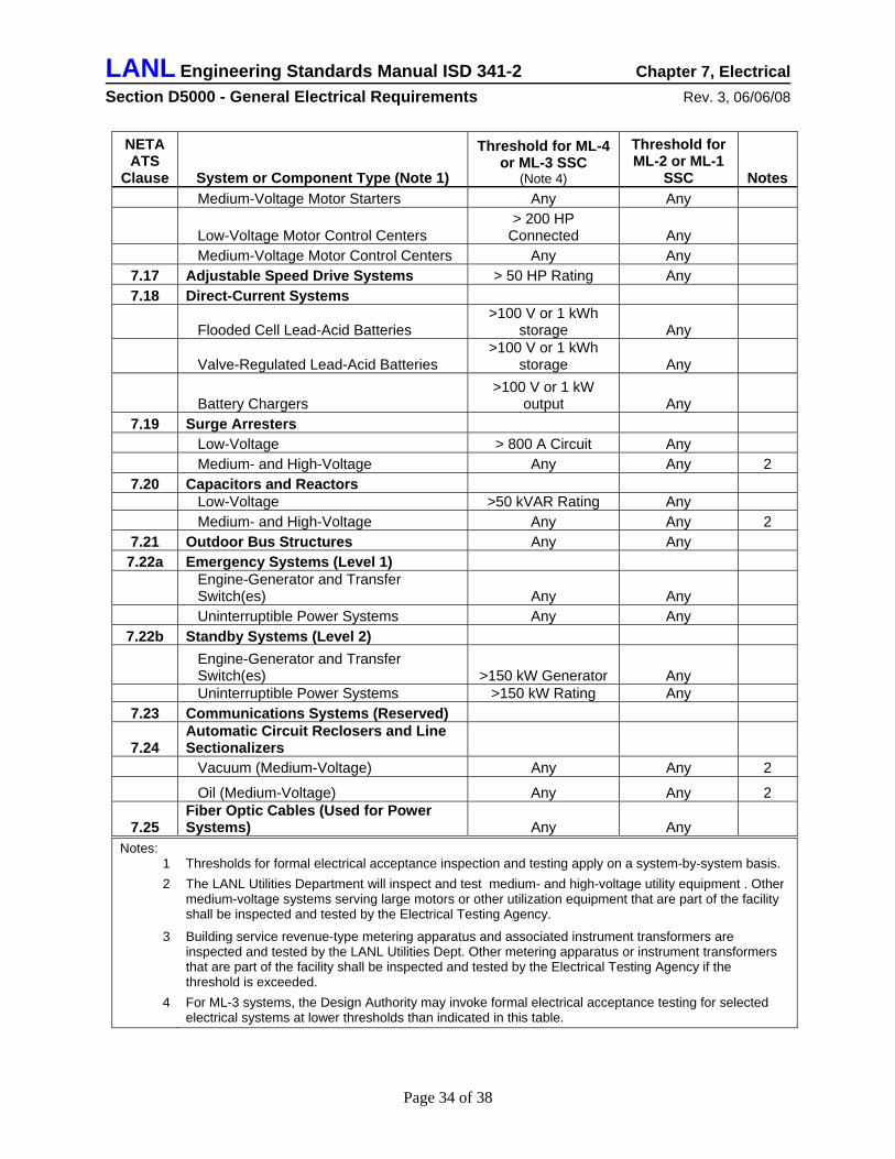
LANL Engineering Standards Manual ISD 341-2 Chapter 7, Electrical Section D5000 - General Electrical Requirements Rev. 3, 06/06/08
NETA ATS
Clause System or Component Type (Note 1)
Threshold for ML-4 or ML-3 SSC
(Note 4)
Threshold for ML-2 or ML-1
SSC Notes Medium-Voltage Motor Starters Any Any
Low-Voltage Motor Control Centers > 200 HP
Connected Any Medium-Voltage Motor Control Centers Any Any
7.17 Adjustable Speed Drive Systems > 50 HP Rating Any 7.18 Direct-Current Systems
Flooded Cell Lead-Acid Batteries >100 V or 1 kWh
storage Any
Valve-Regulated Lead-Acid Batteries >100 V or 1 kWh
storage Any
Battery Chargers >100 V or 1 kW
output Any 7.19 Surge Arresters
Low-Voltage > 800 A Circuit Any Medium- and High-Voltage Any Any 2
7.20 Capacitors and Reactors Low-Voltage >50 kVAR Rating Any Medium- and High-Voltage Any Any 2
7.21 Outdoor Bus Structures Any Any 7.22a Emergency Systems (Level 1)
Engine-Generator and Transfer Switch(es) Any Any
Uninterruptible Power Systems Any Any 7.22b Standby Systems (Level 2)
Engine-Generator and Transfer Switch(es) >150 kW Generator Any
Uninterruptible Power Systems >150 kW Rating Any 7.23 Communications Systems (Reserved)
7.24 Automatic Circuit Reclosers and Line Sectionalizers
Vacuum (Medium-Voltage) Any Any 2
Oil (Medium-Voltage) Any Any 2
7.25 Fiber Optic Cables (Used for Power Systems) Any Any
Notes: 1 Thresholds for formal electrical acceptance inspection and testing apply on a system-by-system basis. 2 The LANL Utilities Department will inspect and test medium- and high-voltage utility equipment . Other
medium-voltage systems serving large motors or other utilization equipment that are part of the facility shall be inspected and tested by the Electrical Testing Agency.
3 Building service revenue-type metering apparatus and associated instrument transformers are inspected and tested by the LANL Utilities Dept. Other metering apparatus or instrument transformers that are part of the facility shall be inspected and tested by the Electrical Testing Agency if the threshold is exceeded.
4 For ML-3 systems, the Design Authority may invoke formal electrical acceptance testing for selected electrical systems at lower thresholds than indicated in this table.
Page 34 of 38
LANL Engineering Standards Manual ISD 341-2 Chapter 7, Electrical Section D5000 - General Electrical Requirements Rev. 3, 06/06/08
C. Perform formal electrical acceptance testing, inspection, and calibration using the services of the LANL Construction Management Division (if qualified) or a qualified independent electrical testing firm.
D. Energize electrical systems only after they have been inspected and tested in accordance with this section and have been inspected and approved by the LANL electrical AHJ.94
12.0 ADDITIONAL REQUIREMENTS FOR SAFETY-RELATED ELECTRICAL SYSTEMS (PROGRAMMATIC AND FACILITY) A. Comply with requirements in DOE O 420.1B Facility Safety in the design of nuclear safety
related electrical structures, systems, and components (SSCs) for Hazard Category 1, 2, and 3 facilities, and other ML-1 and ML-2 systems.
• Note: DOE-STD-1027 interprets Hazard Category 1 facilities as “Category A” reactors, none of which are anticipated at LANL.
• Note: Instrumentation, control, and alarm systems are addressed in LANL ESM Chapter 8.
B. Use the additional guidance provided in DOE G 420.1-1 Implementation Guide for Nonreactor Nuclear Safety Design Criteria and Explosives Safety Criteria.95 The following paragraphs interpret the DOE G 420.1-1 guidance for application at LANL.
C. Use this section along with Chapter 1-General Section Z10, Chapter 10-Hazardous Processes, Chapter 12-Nuclear, and other ESM chapters as applicable.
D. Design electrical SSCs to perform all safety functions with the reliability required by the DSA:
• Design safety-class and other ML-1 electrical SSCs against single-point failure in accordance with the criteria, requirements, and design analysis identified in ANSI/IEEE 379™ Standard Application of the Single-Failure Criterion to Nuclear Power Generating Safety Systems.96
• For safety significant and other ML-2 electrical SSCs, analyze the need for redundant power sources (normal or alternative) on a case-by-case basis. Redundancy may not be needed for safety-significant electrical power systems if it can be shown that there is sufficient response time to provide an alternative source of electrical power.97
E. Use environmental qualification to ensure that safety-class and safety-significant electrical SSCs can perform all safety functions, as determined by the DSA, with no failure mechanism that could lead to common cause failures under postulated service conditions.97 Use the requirements for “mild environmental qualification” from IEEE 323™ unless the environment in which the SSC is located changes significantly because of the design basis accident conditions. Qualification for mild environments shall consist of two elements:
94 Refer to §2.2.5 in LANL ISD 101-13 – Electrical Safety. 95 DOE G 420.1-1 provides an acceptable approach for satisfying the requirements of DOE O 420.1B. 96 DOE O 420.1B, Ch I Section 3.b (8) requires that safety class electrical systems be designed to the basic approach outline in Section 5.2.3 of DOE G 420.1-1. 97 From DOE G 420.1-1 Implementation Guide for Nonreactor Nuclear Safety Design Criteria and Explosives Safety Criteria, Section 5.2.3 Electrical.
Page 35 of 38
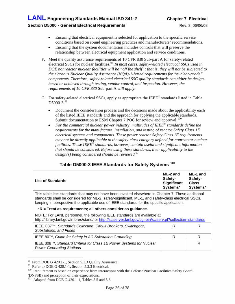
LANL Engineering Standards Manual ISD 341-2 Chapter 7, Electrical Section D5000 - General Electrical Requirements Rev. 3, 06/06/08
• Ensuring that electrical equipment is selected for application to the specific service conditions based on sound engineering practices and manufacturers’ recommendations.
• Ensuring that the system documentation includes controls that will preserve the relationship between electrical equipment application and service conditions.
F. Meet the quality assurance requirements of 10 CFR 830 Sub-part A for safety-related electrical SSCs for nuclear facilities.98 In most cases, safety-related electrical SSCs used in DOE nonreactor nuclear facilities will be “off the shelf”; that is, they will not be subjected to the rigorous Nuclear Quality Assurance (NQA)-1-based requirements for “nuclear-grade” components. Therefore, safety-related electrical SSC quality standards can either be design-based or achieved through testing, vendor control, and inspection. However, the requirements of 10 CFR 830 Sub-part A still apply.
G. For safety-related electrical SSCs, apply as appropriate the IEEE® standards listed in Table D5000-3.99
• Document the consideration process and the decisions made about the applicability each of the listed IEEE standards and the approach for applying the applicable standards. Submit documentation to ESM Chapter 7 POC for review and approval.100
• For the commercial nuclear power industry, multitudes of IEEE® standards define the requirements for the manufacture, installation, and testing of reactor Safety Class 1E electrical systems and components. These power reactor Safety Class 1E requirements may not be directly applicable to the safety-class category defined for nonreactor nuclear facilities. These IEEE® standards, however, contain useful and significant information that should be considered. Before using these standards, their applicability to the design(s) being considered should be reviewed.97
Table D5000-3 IEEE Standards for Safety Systems 101
List of Standards ML-2 and Safety-Significant Systems*
ML-1 and Safety-Class Systems*
This table lists standards that may not have been invoked elsewhere in Chapter 7. These additional standards shall be considered for ML-2, safety-significant, ML-1, and safety-class electrical SSCs, keeping in perspective the applicable use of IEEE standards for the specific application. *R = Treat as requirements; all others consider as guidance. NOTE: For LANL personnel, the following IEEE standards are available at http://library.lanl.gov/infores/stand/ or http://sciserver.lanl.gov/cgi-bin/sciserv.pl?collection=standards
IEEE C37™, Standards Collection: Circuit Breakers, Switchgear, Substations, and Fuses
R R
IEEE 80™, Guide for Safety in AC Substation Grounding R R
IEEE 308™, Standard Criteria for Class 1E Power Systems for Nuclear Power Generating Stations
R
98 From DOE G 420.1-1, Section 5.1.3 Quality Assurance. 99 Refer to DOE G 420.1-1, Section 5.2.3 Electrical. 100 Requirement is based on experience from interactions with the Defense Nuclear Facilities Safety Board (DNFSB) and perception of their expectations. 101 Adapted from DOE G 420.1-1, Tables 5.5 and 5.6
Page 36 of 38
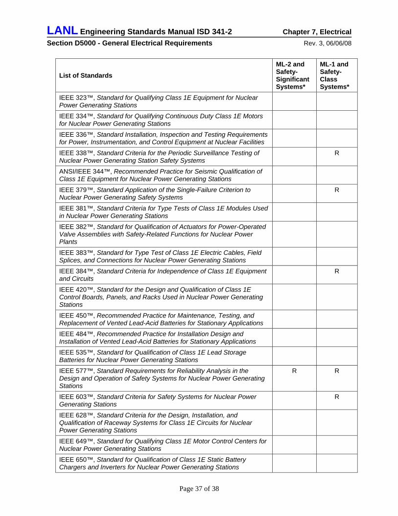
LANL Engineering Standards Manual ISD 341-2 Chapter 7, Electrical Section D5000 - General Electrical Requirements Rev. 3, 06/06/08
List of Standards ML-2 and Safety-Significant Systems*
ML-1 and Safety-Class Systems*
IEEE 323™, Standard for Qualifying Class 1E Equipment for Nuclear Power Generating Stations
IEEE 334™, Standard for Qualifying Continuous Duty Class 1E Motors for Nuclear Power Generating Stations
IEEE 336™, Standard Installation, Inspection and Testing Requirements for Power, Instrumentation, and Control Equipment at Nuclear Facilities
IEEE 338™, Standard Criteria for the Periodic Surveillance Testing of Nuclear Power Generating Station Safety Systems
R
ANSI/IEEE 344™, Recommended Practice for Seismic Qualification of Class 1E Equipment for Nuclear Power Generating Stations
IEEE 379™, Standard Application of the Single-Failure Criterion to Nuclear Power Generating Safety Systems
R
IEEE 381™, Standard Criteria for Type Tests of Class 1E Modules Used in Nuclear Power Generating Stations
IEEE 382™, Standard for Qualification of Actuators for Power-Operated Valve Assemblies with Safety-Related Functions for Nuclear Power Plants
IEEE 383™, Standard for Type Test of Class 1E Electric Cables, Field Splices, and Connections for Nuclear Power Generating Stations
IEEE 384™, Standard Criteria for Independence of Class 1E Equipment and Circuits
R
IEEE 420™, Standard for the Design and Qualification of Class 1E Control Boards, Panels, and Racks Used in Nuclear Power Generating Stations
IEEE 450™, Recommended Practice for Maintenance, Testing, and Replacement of Vented Lead-Acid Batteries for Stationary Applications
IEEE 484™, Recommended Practice for Installation Design and Installation of Vented Lead-Acid Batteries for Stationary Applications
IEEE 535™, Standard for Qualification of Class 1E Lead Storage Batteries for Nuclear Power Generating Stations
IEEE 577™, Standard Requirements for Reliability Analysis in the Design and Operation of Safety Systems for Nuclear Power Generating Stations
R R
IEEE 603™, Standard Criteria for Safety Systems for Nuclear Power Generating Stations
R
IEEE 628™, Standard Criteria for the Design, Installation, and Qualification of Raceway Systems for Class 1E Circuits for Nuclear Power Generating Stations
IEEE 649™, Standard for Qualifying Class 1E Motor Control Centers for Nuclear Power Generating Stations
IEEE 650™, Standard for Qualification of Class 1E Static Battery Chargers and Inverters for Nuclear Power Generating Stations
Page 37 of 38
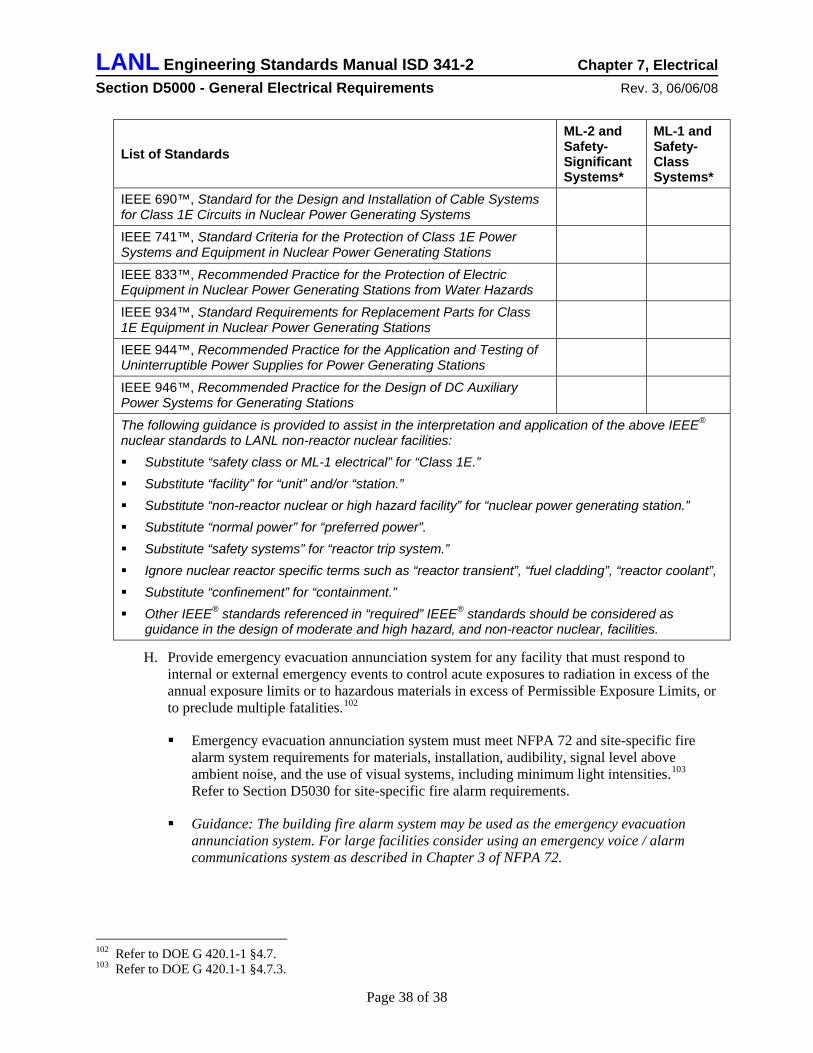
LANL Engineering Standards Manual ISD 341-2 Chapter 7, Electrical Section D5000 - General Electrical Requirements Rev. 3, 06/06/08
Page 38 of 38
List of Standards ML-2 and Safety-Significant Systems*
ML-1 and Safety-Class Systems*
IEEE 690™, Standard for the Design and Installation of Cable Systems for Class 1E Circuits in Nuclear Power Generating Systems
IEEE 741™, Standard Criteria for the Protection of Class 1E Power Systems and Equipment in Nuclear Power Generating Stations
IEEE 833™, Recommended Practice for the Protection of Electric Equipment in Nuclear Power Generating Stations from Water Hazards
IEEE 934™, Standard Requirements for Replacement Parts for Class 1E Equipment in Nuclear Power Generating Stations
IEEE 944™, Recommended Practice for the Application and Testing of Uninterruptible Power Supplies for Power Generating Stations
IEEE 946™, Recommended Practice for the Design of DC Auxiliary Power Systems for Generating Stations
The following guidance is provided to assist in the interpretation and application of the above IEEE® nuclear standards to LANL non-reactor nuclear facilities: Substitute “safety class or ML-1 electrical” for “Class 1E.” Substitute “facility” for “unit” and/or “station.” Substitute “non-reactor nuclear or high hazard facility” for “nuclear power generating station.” Substitute “normal power” for “preferred power”. Substitute “safety systems” for “reactor trip system.” Ignore nuclear reactor specific terms such as “reactor transient”, “fuel cladding”, “reactor coolant”, Substitute “confinement” for “containment.” Other IEEE® standards referenced in “required” IEEE® standards should be considered as
guidance in the design of moderate and high hazard, and non-reactor nuclear, facilities.
H. Provide emergency evacuation annunciation system for any facility that must respond to internal or external emergency events to control acute exposures to radiation in excess of the annual exposure limits or to hazardous materials in excess of Permissible Exposure Limits, or to preclude multiple fatalities.102
Emergency evacuation annunciation system must meet NFPA 72 and site-specific fire alarm system requirements for materials, installation, audibility, signal level above ambient noise, and the use of visual systems, including minimum light intensities.103 Refer to Section D5030 for site-specific fire alarm requirements.
Guidance: The building fire alarm system may be used as the emergency evacuation annunciation system. For large facilities consider using an emergency voice / alarm communications system as described in Chapter 3 of NFPA 72.
102 Refer to DOE G 420.1-1 §4.7. 103 Refer to DOE G 420.1-1 §4.7.3.