Embed Size (px)
Citation preview
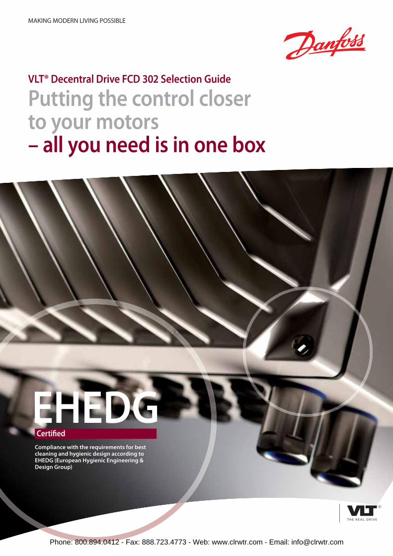
EHEDGCertifi ed
Compliance with the requirements for best cleaning and hygienic design according to EHEDG (European Hygienic Engineering & Design Group)
VLT® Decentral Drive FCD 302 Selection Guide
Putting the control closer to your motors – all you need is in one box
MAKING MODERN LIVING POSSIBLE
Phone: 800.894.0412 - Fax: 888.723.4773 - Web: www.clrwtr.com - Email: [email protected]
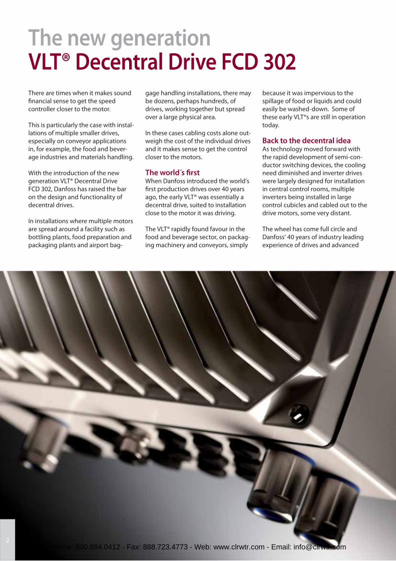
The new generation VLT® Decentral Drive FCD 302There are times when it makes sound
fi nancial sense to get the speed
controller closer to the motor.
This is particularly the case with instal-
lations of multiple smaller drives,
especially on conveyor applications
in, for example, the food and bever-
age industries and materials handling.
With the introduction of the new
generation VLT® Decentral Drive
FCD 302, Danfoss has raised the bar
on the design and functionality of
decentral drives.
In installations where multiple motors
are spread around a facility such as
bottling plants, food preparation and
packaging plants and airport bag-
gage handling installations, there may
be dozens, perhaps hundreds, of
drives, working together but spread
over a large physical area.
In these cases cabling costs alone out-
weigh the cost of the individual drives
and it makes sense to get the control
closer to the motors.
The world s fi rstWhen Danfoss introduced the world’s
fi rst production drives over 40 years
ago, the early VLT® was essentially a
decentral drive, suited to installation
close to the motor it was driving.
The VLT® rapidly found favour in the
food and beverage sector, on packag-
ing machinery and conveyors, simply
because it was impervious to the
spillage of food or liquids and could
easily be washed-down. Some of
these early VLT®s are still in operation
today.
Back to the decentral ideaAs technology moved forward with
the rapid development of semi-con-
ductor switching devices, the cooling
need diminished and inverter drives
were largely designed for installation
in central control rooms, multiple
inverters being installed in large
control cubicles and cabled out to the
drive motors, some very distant.
The wheel has come full circle and
Danfoss’ 40 years of industry leading
experience of drives and advanced
2Phone: 800.894.0412 - Fax: 888.723.4773 - Web: www.clrwtr.com - Email: [email protected]
technological development has led
back to a high performance decentral
format with all the control functional-
ity and performance of larger central
drives but now in an IP 66 enclosure
especially designed to suit multi-
motor applications across a wide
spectrum of industry.
Hygienic design requiredEspecially in food and beverage
production areas, but also in pharma-
ceutical and cosmetic manufacturing
plants, hygiene compliance rules in
sensitive areas are extremely
demanding.
In addition to the standards and
guidelines of the EU, operators are
increasingly observing the rules of the
“European Hygienic Engineering &
Design Group” – called EHEDG. The
EHEDG provides the specifi cations
and guidelines for the comprehen-
sive, proactive protection of food
from contamination with bacteria,
fungi and yeasts during processing.
3
New hygienic trendsEU regulations for the compliance
of hygienic equipment to be used
in the manufacturing of popular
food and beverages are becoming
increasingly tight. For example, in
the beverage industry, still water,
fruit juices and alcohol free beers
are all highly reactive to external
infl uences.
New packaging materials also
raise the demands on the hygienic
conditions. Plastic packaging for
cosmetics, including PET bottles in
the drinks industry, require new
measures as they do not tolerate
heat sterilization or cleaning that
previously rendered glass contain-
ers aseptic.
The result can be summarised under
the heading “Hygienic Design”.
Thus, the responsibility for imple-
menting and achieving these targets
lies with the machine manufacturers
and operators. The hygienic design of
process equipment and components
should be based on a sound combi-
nation of process and mechanical
engineering as well as knowledge in
microbiology.
Danfoss has adopted hygienic
requirements at the initial stage in
developing its drives because upgrad-
ing of existing process equipment
designs to meet hygienic require-
ments is often both expensive and
unsuccessful.
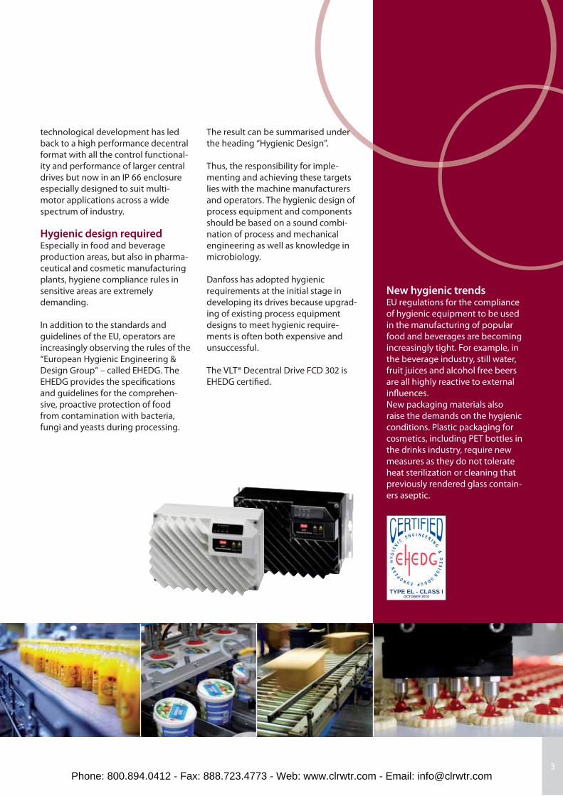
The VLT® Decentral Drive FCD 302 is
EHEDG certifi ed.
TYPE EL - CLASS IOCTOBER 2010
Phone: 800.894.0412 - Fax: 888.723.4773 - Web: www.clrwtr.com - Email: [email protected]
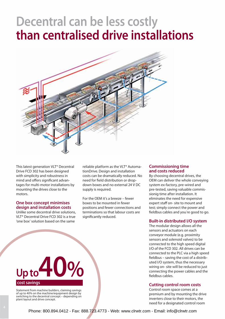
Up to40%cost savings
Statement from machine builders, claiming savings of up to 40% on the machine/equipment design by switching to the decentral concept – depending on plant layout and drive concept.
Decentral can be less costlythan centralised drive installations
4
This latest generation VLT® Decentral
Drive FCD 302 has been designed
with simplicity and robustness in
mind and off ers signifi cant advan-
tages for multi-motor installations by
mounting the drives close to the
motors.
One box concept minimises design and installation costsUnlike some decentral drive solutions,
VLT® Decentral Drive FCD 302 is a true
‘one box’ solution based on the same
Commissioning time and costs reducedBy choosing decentral drives, the
OEM can deliver the whole conveying
system ex-factory, pre-wired and
pre-tested, saving valuable commis-
sionig time after installation. It
eliminates the need for expensive
expert staff on- site to mount and
test; simply connect the power and
fi eldbus cables and you re good to go.
Built-in distributed I/O systemThe modular design allows all the
sensors and actuators on each
conveyor module (e.g. proximity
sensors and sole noid valves) to be
connected to the high speed digital
I/O of the FCD 302. All drives can be
con nected to the PLC via a high speed
fi eldbus – saving the cost of a distrib-
uted I/O system, thus the necessary
wiring on- site will be reduced to just
connecting the power cables and the
fi eldbus cables.
Cutting control room costs Control room space comes at a
premium and by mounting the drive
inverters close to their motors, the
need for a designated control room
reliable platform as the VLT® Automa-
tionDrive. Design and installation
costs can be dramatically reduced. No
need for fi eld distribution or drop-
down boxes and no external 24 V DC
supply is required.
For the OEM it’s a breeze – fewer
boxes to be mounted in fewer
positions and fewer connections and
terminations so that labour costs are
signifi cantly reduced.
Phone: 800.894.0412 - Fax: 888.723.4773 - Web: www.clrwtr.com - Email: [email protected]
and expensive control cubicles is
largely eliminated, representing a
substantial cost saving in fi rst-cost
terms.
Power cabling costs reducedEven greater savings are off ered by
the reduction in cabling costs, taking
advantage of the loop-in, loop-out
mains cabling using unscreened
cables.
Installing the drives closer to their
motors eliminates the need for long
and costly screened cables from the
drive to the motor.
Control cabling simplifi edSerial communications and fi eld-bus
options also simplify and cost-reduce
control wiring installation and allow
central control of the entire system.
Hygienic designAfter years working with the food and
beverage industry, Danfoss knows
better than most the need for a
robust, watertight construction that
resists can be cleaned down quickly
and easily, shortening the mainte-
nance window.
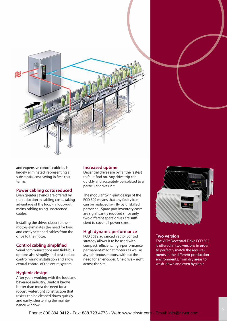
Increased uptimeDecentral drives are by far the fastest
to fault-fi nd on. Any drive trip can
quickly and accurately be isolated to a
particular drive unit.
The modular twin-part design of the
FCD 302 means that any faulty item
can be replaced swiftly by unskilled
personnel. Spare part inventory costs
are signifi cantly reduced since only
two diff erent spare drives are suffi -
cient to cover all power sizes.
High dynamic performanceFCD 302’s advanced vector control
strategy allows it to be used with
compact, effi cient, high-performance
permanent-magnet motors as well as
asynchronous motors, without the
need for an encoder. One drive – right
across the site.
Two versionThe VLT® Decentral Drive FCD 302
is off ered in two versions in order
to perfectly match the require-
ments in the diff erent production
environments, from dry areas to
wash-down and even hygienic.
5Phone: 800.894.0412 - Fax: 888.723.4773 - Web: www.clrwtr.com - Email: [email protected]
Where Decentral Drives succeed
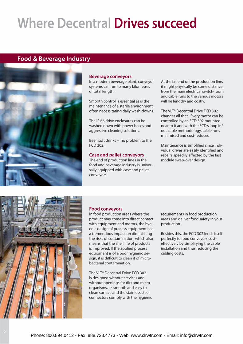
Beverage conveyorsIn a modern beverage plant, conveyor
systems can run to many kilometres
of total length.
Smooth control is essential as is the
maintenance of a sterile environment,
often necessitating daily wash-downs.
The IP 66 drive enclosures can be
washed down with power hoses and
aggressive cleaning solutions.
Beer, soft drinks – no problem to the
FCD 302.
Case and pallet conveyorsThe end of production lines in the
food and beverage industry is univer-
sally equipped with case and pallet
conveyors.
Food conveyorsIn food production areas where the
product may come into direct contact
with equipment and motors, the hygi-
enic design of process equipment has
a tremendous impact on diminishing
the risks of contamination, which also
means that the shelf life of products
is improved. If the applied process
equipment is of a poor hygienic de-
sign, it is diffi cult to clean it of micro-
bacterial contamination.
The VLT® Decentral Drive FCD 302
is designed without crevices and
without openings for dirt and micro-
organisms, its smooth and easy to
clean surface and the stainless steel
connectors comply with the hygienic
6
Food & Beverage Industry
At the far end of the production line,
it might physically be some distance
from the main electrical switch-room
and cable runs to the various motors
will be lengthy and costly.
The VLT® Decentral Drive FCD 302
changes all that. Every motor can be
controlled by an FCD 302 mounted
near to it and with the FCD’s loop in/
out cable methodology, cable runs
minimised and cost-reduced.
Maintenance is simplifi ed since indi-
vidual drives are easily identifi ed and
repairs speedily eff ected by the fast
module swap-over design.
requirements in food production
areas and deliver food safety in your
production.
Besides this, the FCD 302 lends itself
perfectly to food conveyors cost-
eff ectively by simplifying the cable
installation and thus reducing the
cabling costs.
Phone: 800.894.0412 - Fax: 888.723.4773 - Web: www.clrwtr.com - Email: [email protected]
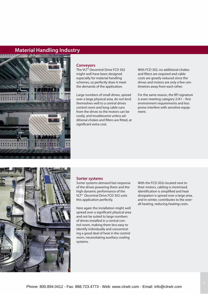
ConveyorsThe VLT® Decentral Drive FCD 302
might well have been designed
especially for material handling
schemes, so perfectly does it meet
the demands of the application.
Large numbers of small drives, spread
over a large physical area, do not lend
themselves well to a central drives
control room and long cable runs
from the drives to the motors can be
costly, and troublesome unless ad-
ditional chokes and fi lters are fi tted, at
signifi cant extra cost.
Sorter systemsSorter systems demand fast response
of the drives powering them and the
high dynamic performance of the
VLT® Decentral Drive FCD 302 suits
this application perfectly.
Here again the installation might well
spread over a signifi cant physical area
and not be suited to large numbers
of drives installed in a central con-
trol room, making them less easy to
identify individually and concentrat-
ing a good deal of heat in the control
room, necessitating auxiliary cooling
systems.
7
Material Handling Industry
With FCD 302, no additional chokes
and fi lters are required and cable
costs are greatly reduced since the
drives and motors are only a few cen-
timetres away from each other.
For the same reason, the RFI signature
is even meeting category 2/A1 – fi rst
environment requirements and less
prone interfere with sensitive equip-
ment.
With the FCD 302s located next to
their motors, cabling is minimised,
identifi cation is simplifi ed and heat
dissipation is spread over a large area,
and in winter, contributes to the over-
all heating, reducing heating costs.
Phone: 800.894.0412 - Fax: 888.723.4773 - Web: www.clrwtr.com - Email: [email protected]
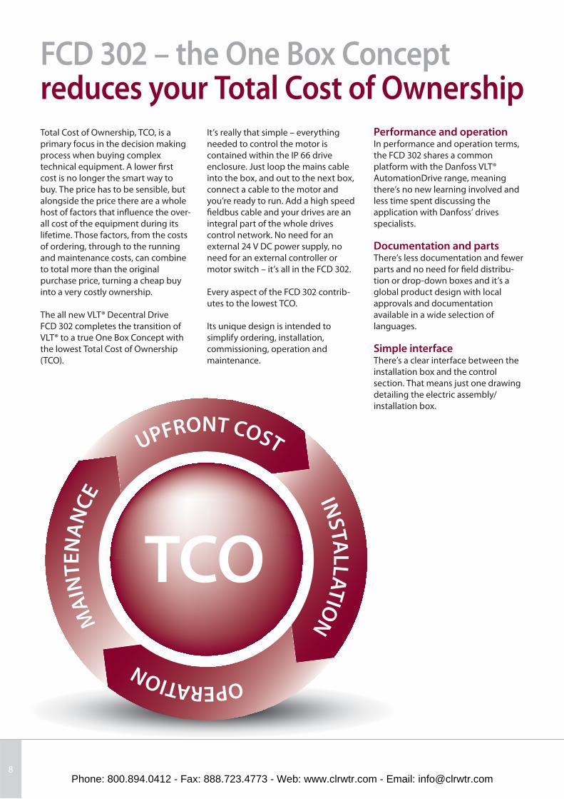
TCO
UPFRONT COST
INSTA
LLATION
OPERATION
M
AIN
TEN
AN
CE
M
AIN
TEN
AN
CE
M
AIN
TEN
AN
CE
8
FCD 302 – the One Box Concept reduces your Total Cost of OwnershipTotal Cost of Ownership, TCO, is a
primary focus in the decision making
process when buying complex
technical equipment. A lower fi rst
cost is no longer the smart way to
buy. The price has to be sensible, but
alongside the price there are a whole
host of factors that infl uence the over-
all cost of the equipment during its
lifetime. Those factors, from the costs
of ordering, through to the running
and maintenance costs, can combine
to total more than the original
purchase price, turning a cheap buy
into a very costly ownership.
The all new VLT® Decentral Drive
FCD 302 completes the transition of
VLT® to a true One Box Concept with
the lowest Total Cost of Ownership
(TCO).
Performance and operationIn performance and operation terms,
the FCD 302 shares a common
platform with the Danfoss VLT®
AutomationDrive range, meaning
there’s no new learning involved and
less time spent discussing the
application with Danfoss’ drives
specialists.
Documentation and partsThere’s less documentation and fewer
parts and no need for fi eld distribu-
tion or drop-down boxes and it’s a
global product design with local
approvals and documentation
available in a wide selection of
languages.
Simple interfaceThere’s a clear interface between the
installation box and the control
section. That means just one drawing
detailing the electric assembly/
installation box.
It’s really that simple – everything
needed to control the motor is
contained within the IP 66 drive
enclosure. Just loop the mains cable
into the box, and out to the next box,
connect a cable to the motor and
you’re ready to run. Add a high speed
fi eldbus cable and your drives are an
integral part of the whole drives
control network. No need for an
external 24 V DC power supply, no
need for an external controller or
motor switch – it’s all in the FCD 302.
Every aspect of the FCD 302 contrib-
utes to the lowest TCO.
Its unique design is intended to
simplify ordering, installation,
commissioning, operation and
maintenance.
Phone: 800.894.0412 - Fax: 888.723.4773 - Web: www.clrwtr.com - Email: [email protected]
9
OrderhandlingOrdering is simplifi ed by the limited
number of ordering lines required.
This means there is less maintenance
of purchasing orders and reduced risk
of ordering the wrong parts – or
missing parts altogether.
At incoming goods there are fewer
parts to check-in so less time taken to
compare delivery to original order,
less risk of missing parts, fewer
inventory locations and less space
required for storage.
InstallationWith fewer numbers of boxes to be
mounted, in fewer locations, that’s a
saving in time and man-hours. Fewer
cables cut time and cost and less
money spent on cable management
systems. No external 24 V DC supply
is required so that’s another cable less
and the cost of a central dc power
supply out of the equation. Fewer
connections and terminations also
reduces labour cost at installation and
lowers the likelihood of failure due to
poor or wrong connectivity.
CommissioningThe One Box Concept means that
commissioning time is signifi cantly
reduced. A multi-lingual graphical
display with on-board manual means
no lost time searching for the manual.
The HMI (human machine interface),
based upon the award winning VLT®
display, has a customised display to
display just the parameters you
decide are important to you.
The FCD 302 also makes use of the
VLT® Motion Control Tool MCT 10,
proven in use in the fi eld with
thousands of VLT® drives. Pro-
grammes can be stored and shared,
drive to drive; OEMs can pre-commis-
sion drives prior to despatch, making
for faster commissioning of the
completed installation on-site.
Flexible PC connection through USB,
RS485 and HPFP and a capability
facilitate programme is available as
download via internet to update the
OEM’s factory settings at the end-
user’s plant, which simplifi es and
reduces cost of commissioning.
ServiceThe FCD 302 is probably the simplest
and easiest drive to service which
Danfoss has ever developed. Self-
diagnostic troubleshooting combined
with an on-board manual accessed
through the graphical display makes
faultfi nding and troubleshooting
easy. All alarms and operations are
logged in the memory for easy access
and interpretation of past events.
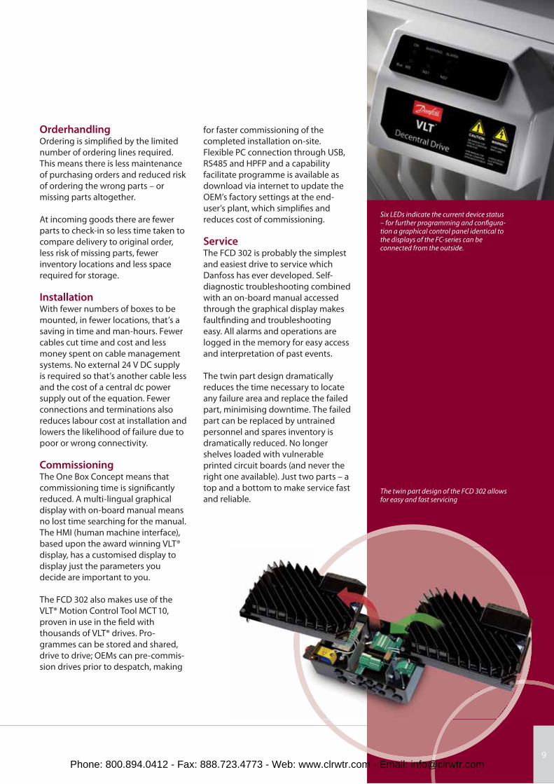
The twin part design dramatically
reduces the time necessary to locate
any failure area and replace the failed
part, minimising downtime. The failed
part can be replaced by untrained
personnel and spares inventory is
dramatically reduced. No longer
shelves loaded with vulnerable
printed circuit boards (and never the
right one available). Just two parts – a
top and a bottom to make service fast
and reliable.
Six LEDs indicate the current device status – for further programming and confi gura-tion a graphical control panel identical to the displays of the FC-series can be connected from the outside.
The twin part design of the FCD 302 allows for easy and fast servicing
Phone: 800.894.0412 - Fax: 888.723.4773 - Web: www.clrwtr.com - Email: [email protected]
10
FCD 302 – the One Box Concept All you need is in one boxIntegrated 24 V supply24 V DC control supply is provided by
the drive supplying remote I/Os
distribution.
Power loopingThe new FCD 302 facilitates internal
power looping. Terminals for 6 mm2
(big box) or 4 mm2 (small box) power
cable inside the enclosure allows
connection of multiple units in the
same branch.
Ethernet switchIntegrated Ethernet switch/ hub with
the two RJ-45 ports are available in
the drive for easy daisy-chaining of
Ethernet communication.
Fieldbusses are routed easily, without
adding commissioning time, by
connecting Ethernet or Profi bus
based fi eld buses to a M12 pluggable
interface.
PROFIBUS communicationStraight and easy access to the spring-
loaded terminals for daisy-chaining.
Decentral I/OConnection of all input/output
devices is via IP 67 rated M12 connec-
tors on the FCD 302.
Control terminalsSpecially developed spring-loaded
cage clamps enhance reliability and
facilitate easy commissioning and
service.
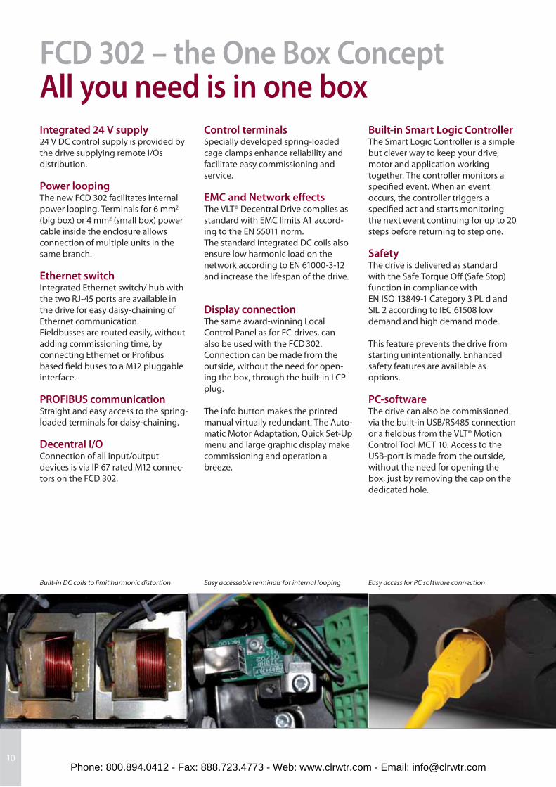
EMC and Network eff ects The VLT® Decentral Drive complies as
standard with EMC limits A1 accord-
ing to the EN 55011 norm.
The standard integrated DC coils also
ensure low harmonic load on the
network according to EN 61000-3-12
and increase the lifespan of the drive.
Display connectionThe same award-winning Local
Control Panel as for FC-drives, can
also be used with the FCD 302.
Connection can be made from the
outside, without the need for open-
ing the box, through the built-in LCP
plug.
The info button makes the printed
manual virtually redundant. The Auto-
matic Motor Adaptation, Quick Set-Up
menu and large graphic display make
commissioning and operation a
breeze.
Built-in Smart Logic ControllerThe Smart Logic Controller is a simple
but clever way to keep your drive,
motor and application working
together. The controller monitors a
specifi ed event. When an event
occurs, the controller triggers a
specifi ed act and starts monitoring
the next event continuing for up to 20
steps before returning to step one.
SafetyThe drive is delivered as standard
with the Safe Torque Off (Safe Stop)
function in compliance with
EN ISO 13849-1 Category 3 PL d and
SIL 2 according to IEC 61508 low
demand and high demand mode.
This feature prevents the drive from
starting unintentionally. Enhanced
safety features are available as
options.
PC-softwareThe drive can also be commissioned
via the built-in USB/RS485 connection
or a fi eldbus from the VLT® Motion
Control Tool MCT 10. Access to the
USB-port is made from the outside,
without the need for opening the
box, just by removing the cap on the
dedicated hole.
Built-in DC coils to limit harmonic distortion Easy access for PC software connectionEasy accessable terminals for internal looping
Phone: 800.894.0412 - Fax: 888.723.4773 - Web: www.clrwtr.com - Email: [email protected]
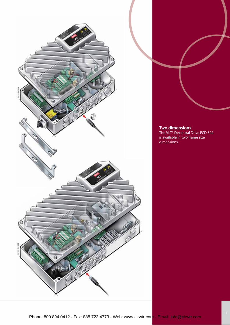
Two dimensionsThe VLT® Decentral Drive FCD 302
is available in two frame size
dimensions.
11Phone: 800.894.0412 - Fax: 888.723.4773 - Web: www.clrwtr.com - Email: [email protected]
12
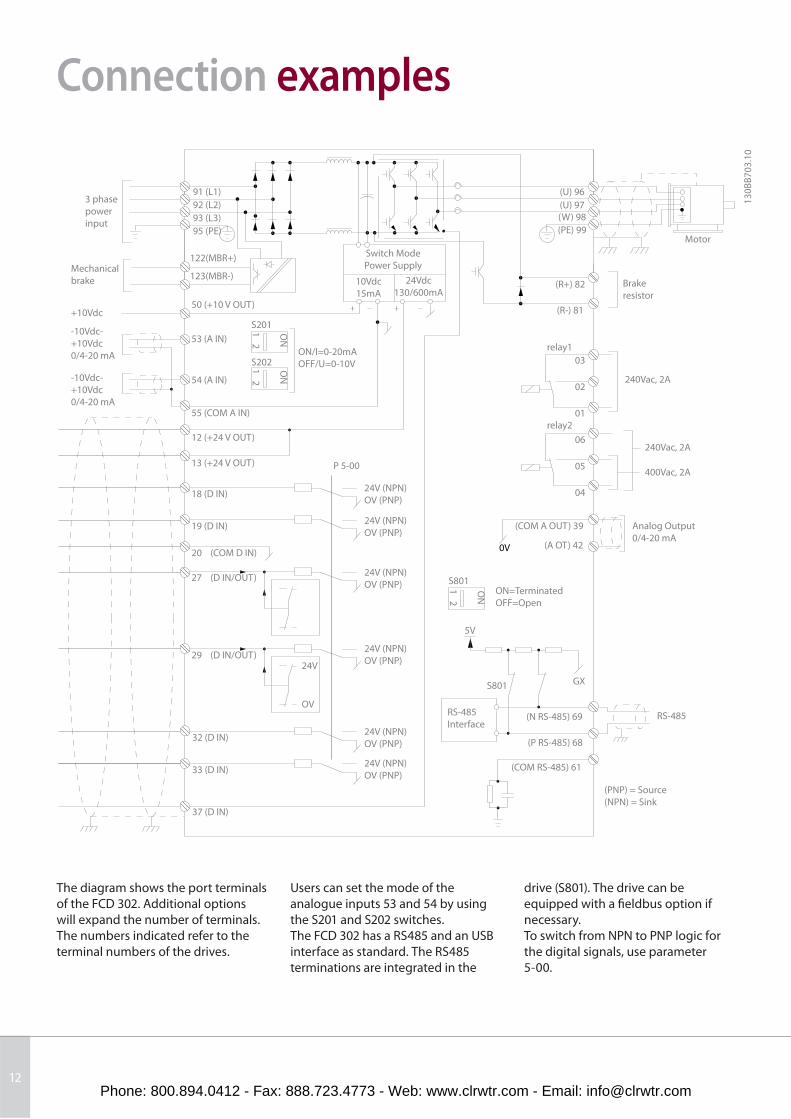
Connection examples
3 phase
power
input
Mechanical
brake
+10Vdc
-10Vdc-
+10Vdc
0/4-20 mA
-10Vdc-
+10Vdc
0/4-20 mA
91 (L1)
92 (L2)
93 (L3)
95 (PE)
122(MBR+)
123(MBR-)
50 (+10 V OUT)
53 (A IN)
54 (A IN)
55 (COM A IN)
12 (+24 V OUT)
13 (+24 V OUT)
18 (D IN)
19 (D IN)
20 (COM D IN)
27 (D IN/OUT)
29 (D IN/OUT)24V
OV
32 (D IN)
33 (D IN)
37 (D IN)
S201
S202ON/I=0-20mA
OFF/U=0-10V
P 5-00
24V (NPN)
OV (PNP)
24V (NPN)
OV (PNP)
24V (NPN)
OV (PNP)
24V (NPN)
OV (PNP)
24V (NPN)
OV (PNP)
24V (NPN)
OV (PNP)
Switch Mode
Power Supply
10Vdc
15mA
24Vdc
130/600mA
(U) 96
(U) 97(W) 98
(PE) 99Motor
Brake
resistor(R+) 82
(R-) 81
relay1
relay2
03
02
01
06
05
04
240Vac, 2A
240Vac, 2A
400Vac, 2A
Analog Output
0/4-20 mA
(COM A OUT) 39
(A OT) 42
ON=Terminated
OFF=Open
S801
S801 GX
(N RS-485) 69
(P RS-485) 68
5V
RS-485
Interface
(COM RS-485) 61
(PNP) = Source
(NPN) = Sink
RS-485
ON
1 2
ON
1 2
ON
1 2
13
0B
B7
03
.10
0V
The diagram shows the port terminals
of the FCD 302. Additional options
will expand the number of terminals.
The numbers indicated refer to the
terminal numbers of the drives.
Users can set the mode of the
analogue inputs 53 and 54 by using
the S201 and S202 switches.
The FCD 302 has a RS485 and an USB
interface as standard. The RS485
terminations are integrated in the
drive (S801). The drive can be
equipped with a fi eldbus option if
necessary.
To switch from NPN to PNP logic for
the digital signals, use parameter
5-00.
Phone: 800.894.0412 - Fax: 888.723.4773 - Web: www.clrwtr.com - Email: [email protected]
13
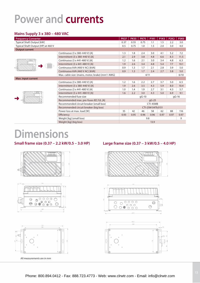
Power and currents
Large frame size (0.37 – 3 kW/0.5 – 4.0 HP)
Mains Supply 3 x 380 – 480 VAC Frequency Converter PK37 PK55 PK75 P1K1 P1K5 P2K2 P3K0
Typical Shaft Output [kW] 0.37 0.55 0.75 1.1 1.5 2.2 3.0
Typical Shaft Output [HP] at 460 V 0.5 0.75 1.0 1.5 2.0 3.0 4.0
Output current
Continuous (3 x 380-440 V) [A] 1.3 1.8 2.4 3.0 4.1 5.2 7.2
Intermittent (3 x 380-440 V) [A] 2.1 2.9 3.8 4.8 6.6 8.3 11.5
Continuous (3 x 441-480 V) [A] 1.2 1.6 2.1 3.0 3.4 4.8 6.3
Intermittent (3 x 441-480 V) [A] 1.9 2.6 3.4 4.8 5.4 7.7 10.1
Continuous kVA (400 V AC) [kVA] 0.9 1.3 1.7 2.1 2.8 3.9 5.0
Continuous kVA (460 V AC) [kVA] 0.9 1.3 1.7 2.4 2.7 3.8 5.0
Max. cable size: (mains, motor, brake) [mm2/ AWG] 4/11 6/10
Max. input current
Continuous (3 x 380-440 V) [A] 1.2 1.6 2.2 2.7 3.7 5.0 6.5
Intermittent (3 x 380-440 V) [A] 1.9 2.6 3.5 4.3 5.9 8.0 10.4
Continuous (3 x 441-480 V) [A] 1.0 1.4 1.9 2.7 3.1 4.3 5.7
Intermittent (3 x 441-480 V) [A] 1.6 2.2 3.0 4.3 5.0 6.9 9.1
Recommended fuse size gG-10 gG-16
Recommended max. pre-fuses IEC/UL [A] gG-25
Recommended circuit breaker (small box) CTI-45MB
Recommended circuit breaker (big box) CTI-25M 047b3151
Power loss at max. load [W] 35 42 46 58 62 88 116
Effi ciency 0.93 0.95 0.96 0.96 0.97 0.97 0.97
Weight [kg] (small box) 9.8 X
Weight [kg] (big box) 13.9
➜
➜
DimensionsSmall frame size (0.37 – 2.2 kW/0.5 – 3.0 HP)
All measurements are in mm
Phone: 800.894.0412 - Fax: 888.723.4773 - Web: www.clrwtr.com - Email: [email protected]
14
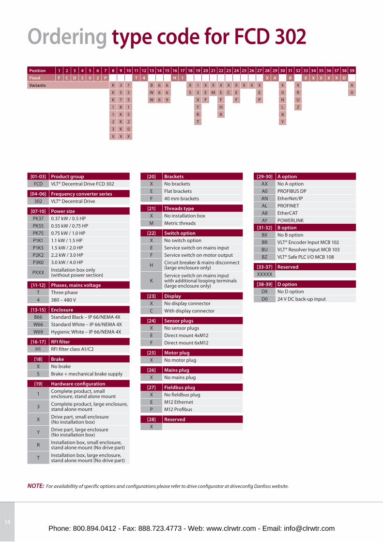
Ordering type code for FCD 302
Position 1 2 3 4 5 6 7 8 9 10 11 12 13 14 15 16 17 18 19 20 21 22 23 24 25 26 27 28 29 30 31 32 33 34 35 36 37 38 39
Fixed F C D 3 0 2 P T 4 H 1 X A B X X X X X D
Variants K 3 7 B 6 6 X 1 X X X X X X X X X X X
K 5 5 W 6 6 S 3 E M E C E E 0 R 0
K 7 5 W 6 9 X F F F P N U
1 K 1 Y H L Z
1 K 5 R K 8
2 K 2 T Y
3 K 0
X X X
NOTE: For availabillity of specifi c options and confi gurations please refer to drive confi gurator at driveconfi g Danfoss website.
[01-03] Product group
FCD VLT® Decentral Drive FCD 302
[04-06] Frequency converter series
302 VLT® Decentral Drive
[07-10] Power size
PK37 0.37 kW / 0.5 HP
PK55 0.55 kW / 0.75 HP
PK75 0.75 kW / 1.0 HP
P1K1 1.1 kW / 1.5 HP
P1K5 1.5 kW / 2.0 HP
P2K2 2.2 kW / 3.0 HP
P3K0 3.0 kW / 4.0 HP
PXXXInstallation box only (without power section)
[11-12] Phases, mains voltage
T Three phase
4 380 – 480 V
[13-15] Enclosure
B66 Standard Black – IP 66/NEMA 4X
W66 Standard White – IP 66/NEMA 4X
W69 Hygienic White – IP 66/NEMA 4X
[16-17] RFI fi lter
H1 RFI fi lter class A1/C2
[18] Brake
X No brake
S Brake + mechanical brake supply
[19] Hardware confi guration
1Complete product, small enclosure, stand alone mount
3Complete product, large enclosure, stand alone mount
XDrive part, small enclosure (No installation box)
YDrive part, large enclosure (No installation box)
RInstallation box, small enclosure, stand alone mount (No drive part)
TInstallation box, large enclosure, stand alone mount (No drive part)
[20] Brackets
X No brackets
E Flat brackets
F 40 mm brackets
[21] Threads type
X No installation box
M Metric threads
[22] Switch option
X No switch option
E Service switch on mains input
F Service switch on motor output
HCircuit breaker & mains disconnect (large enclosure only)
KService switch on mains input with additional looping terminals (large enclosure only)
[23] Display
X No display connector
C With display connector
[24] Sensor plugs
X No sensor plugs
E Direct mount 4xM12
F Direct mount 6xM12
[25] Motor plug
X No motor plug
[26] Mains plug
X No mains plug
[27] Fieldbus plug
X No fi eldbus plug
E M12 Ethernet
P M12 Profi bus
[28] Reserved
X
[29-30] A option
AX No A option
A0 PROFIBUS DP
AN EtherNet/IP
AL PROFINET
A8 EtherCAT
AY POWERLINK
[31-32] B option
BX No B option
BR VLT® Encoder Input MCB 102
BU VLT® Resolver Input MCB 103
BZ VLT® Safe PLC I/O MCB 108
[33-37] Reserved
XXXXX
[38-39] D option
DX No D option
D0 24 V DC back-up input
Phone: 800.894.0412 - Fax: 888.723.4773 - Web: www.clrwtr.com - Email: [email protected]
15
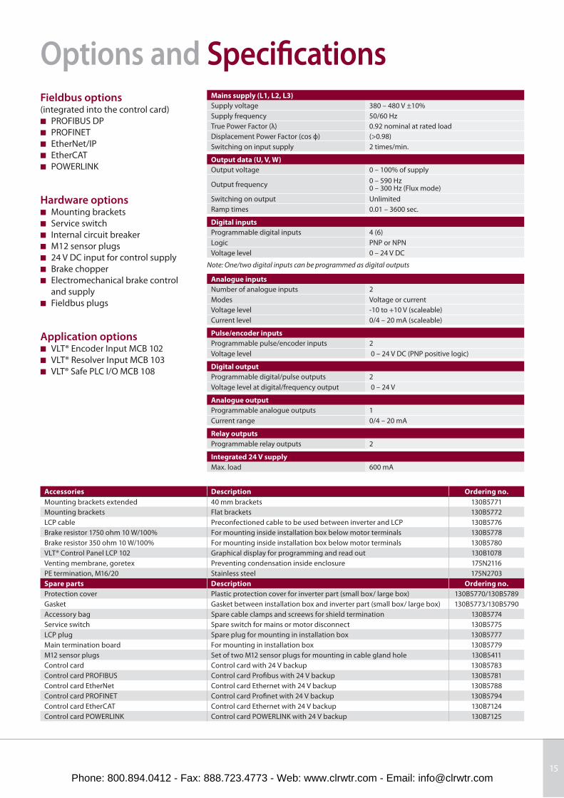
Options and Specifi cationsFieldbus options(integrated into the control card)
■ PROFIBUS DP
■ PROFINET
■ EtherNet/IP
■ EtherCAT
■ POWERLINK
Hardware options■ Mounting brackets
■ Service switch
■ Internal circuit breaker
■ M12 sensor plugs
■ 24 V DC input for control supply
■ Brake chopper
■ Electromechanical brake control
and supply
■ Fieldbus plugs
Application options■ VLT® Encoder Input MCB 102
■ VLT® Resolver Input MCB 103
■ VLT® Safe PLC I/O MCB 108
Mains supply (L1, L2, L3)
Supply voltage 380 – 480 V ±10%
Supply frequency 50/60 Hz
True Power Factor (λ) 0.92 nominal at rated load
Displacement Power Factor (cos ф) (>0.98)
Switching on input supply 2 times/min.
Output data (U, V, W)
Output voltage 0 – 100% of supply
Output frequency0 – 590 Hz0 – 300 Hz (Flux mode)
Switching on output Unlimited
Ramp times 0.01 – 3600 sec.
Digital inputs
Programmable digital inputs 4 (6)
Logic PNP or NPN
Voltage level 0 – 24 V DC
Note: One/two digital inputs can be programmed as digital outputs
Analogue inputs
Number of analogue inputs 2
Modes Voltage or current
Voltage level -10 to +10 V (scaleable)
Current level 0/4 – 20 mA (scaleable)
Pulse/encoder inputs
Programmable pulse/encoder inputs 2
Voltage level 0 – 24 V DC (PNP positive logic)
Digital output
Programmable digital/pulse outputs 2
Voltage level at digital/frequency output 0 – 24 V
Analogue output
Programmable analogue outputs 1
Current range 0/4 – 20 mA
Relay outputs
Programmable relay outputs 2
Integrated 24 V supply
Max. load 600 mA
Accessories Description Ordering no.
Mounting brackets extended 40 mm brackets 130B5771
Mounting brackets Flat brackets 130B5772
LCP cable Preconfectioned cable to be used between inverter and LCP 130B5776
Brake resistor 1750 ohm 10 W/100% For mounting inside installation box below motor terminals 130B5778
Brake resistor 350 ohm 10 W/100% For mounting inside installation box below motor terminals 130B5780
VLT® Control Panel LCP 102 Graphical display for programming and read out 130B1078
Venting membrane, goretex Preventing condensation inside enclosure 175N2116
PE termination, M16/20 Stainless steel 175N2703
Spare parts Description Ordering no.
Protection cover Plastic protection cover for inverter part (small box/ large box) 130B5770/130B5789
Gasket Gasket between installation box and inverter part (small box/ large box) 130B5773/130B5790
Accessory bag Spare cable clamps and screews for shield termination 130B5774
Service switch Spare switch for mains or motor disconnect 130B5775
LCP plug Spare plug for mounting in installation box 130B5777
Main termination board For mounting in installation box 130B5779
M12 sensor plugs Set of two M12 sensor plugs for mounting in cable gland hole 130B5411
Control card Control card with 24 V backup 130B5783
Control card PROFIBUS Control card Profi bus with 24 V backup 130B5781
Control card EtherNet Control card Ethernet with 24 V backup 130B5788
Control card PROFINET Control card Profi net with 24 V backup 130B5794
Control card EtherCAT Control card Ethernet with 24 V backup 130B7124
Control card POWERLINK Control card POWERLINK with 24 V backup 130B7125
Phone: 800.894.0412 - Fax: 888.723.4773 - Web: www.clrwtr.com - Email: [email protected]
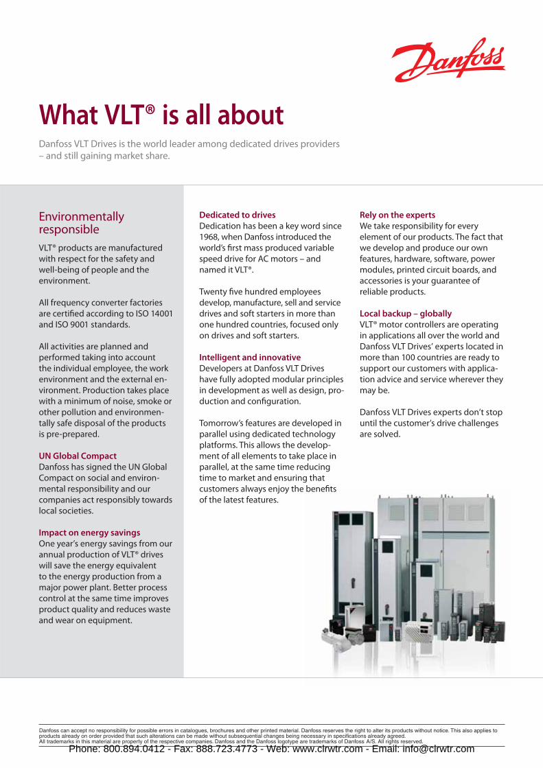
Environmentally responsible
VLT® products are manufactured
with respect for the safety and
well-being of people and the
environment.
All frequency converter factories
are certifi ed according to ISO 14001
and ISO 9001 standards.
All activities are planned and
performed taking into account
the individual employee, the work
environment and the external en-
vironment. Production takes place
with a minimum of noise, smoke or
other pollution and environmen-
tally safe disposal of the products
is pre-prepared.
UN Global Compact
Danfoss has signed the UN Global
Compact on social and environ-
mental responsibility and our
companies act responsibly towards
local societies.
Impact on energy savings
One year’s energy savings from our
annual production of VLT® drives
will save the energy equivalent
to the energy production from a
major power plant. Better process
control at the same time improves
product quality and reduces waste
and wear on equipment.
What VLT® is all aboutDanfoss VLT Drives is the world leader among dedicated drives providers – and still gaining market share.
Dedicated to drives
Dedication has been a key word since
1968, when Danfoss introduced the
world’s fi rst mass produced variable
speed drive for AC motors – and
named it VLT®.
Twenty fi ve hundred employees
develop, manufacture, sell and service
drives and soft starters in more than
one hundred countries, focused only
on drives and soft starters.
Intelligent and innovative
Developers at Danfoss VLT Drives
have fully adopted modular principles
in development as well as design, pro-
duction and confi guration.
Tomorrow’s features are developed in
parallel using dedicated technology
platforms. This allows the develop-
ment of all elements to take place in
parallel, at the same time reducing
time to market and ensuring that
customers always enjoy the benefi ts
of the latest features.
Rely on the experts
We take responsibility for every
element of our products. The fact that
we develop and produce our own
features, hardware, software, power
modules, printed circuit boards, and
accessories is your guarantee of
reliable products.
Local backup – globally
VLT® motor controllers are operating
in applications all over the world and
Danfoss VLT Drives’ experts located in
more than 100 countries are ready to
support our customers with applica-
tion advice and service wherever they
may be.
Danfoss VLT Drives experts don’t stop
until the customer’s drive challenges
are solved.
Phone: 800.894.0412 - Fax: 888.723.4773 - Web: www.clrwtr.com - Email: [email protected]