Embed Size (px)
Citation preview
Data CenterteChnology Design guiDe
August 2013
table of Contents
Table of Contents
Preface ........................................................................................................................................1
CVD Navigator .............................................................................................................................2use Cases .................................................................................................................................. 2scope ......................................................................................................................................... 2Proficiency .................................................................................................................................. 3
Introduction .................................................................................................................................4technology use Cases ............................................................................................................... 4
use Case: Flexible ethernet network Foundation for growth and scale ................................. 4use Case: Virtual Machine Mobility within the Data Center ..................................................... 5use Case: secure Access to Data Center Resources ............................................................ 5
Design overview ......................................................................................................................... 5Data Center Foundation .......................................................................................................... 6Data Center services ............................................................................................................. 6user services ......................................................................................................................... 6ethernet infrastructure ............................................................................................................ 8storage infrastructure ............................................................................................................. 8Compute Connectivity ............................................................................................................ 8network security .................................................................................................................... 9
Physical Environment .................................................................................................................10Design overview ....................................................................................................................... 10
Power ................................................................................................................................... 10Cooling ................................................................................................................................. 10equipment Racking ................................................................................................................11summary ...............................................................................................................................11
table of Contents
Ethernet Infrastructure ...............................................................................................................12Design overview ........................................................................................................................12
Resilient Data Center Core ....................................................................................................14ethernet Fabric extension ..................................................................................................... 15Quality of service ................................................................................................................. 16
Deployment Details ................................................................................................................... 18Configuring ethernet out-of-Band Management .................................................................. 18Configuring the Data Center Core setup and layer 2 ethernet ............................................ 29Configuring the Data Center Core iP Routing ....................................................................... 47Configuring Fabric extender Connectivity ............................................................................. 58
Storage Infrastructure ................................................................................................................66Design overview ....................................................................................................................... 66
iP-based storage options .................................................................................................... 66Fibre Channel storage .......................................................................................................... 66VsAns .................................................................................................................................. 67Zoning ................................................................................................................................. 67Device Aliases ..................................................................................................................... 68storage Array tested ........................................................................................................... 68
Deployment Details ................................................................................................................... 69Configuring Fibre Channel sAn on Cisco nexus 5500uP .................................................... 69Configuring Cisco MDs 9148 switch sAn expansion ........................................................... 81Configuring FCoe host Connectivity .................................................................................... 89Cisco nexus 5500uP Configuration for FCoe ...................................................................... 91
Compute Connectivity ...............................................................................................................96Design overview ....................................................................................................................... 96Cisco nexus Virtual Port Channel ............................................................................................. 97Cisco nexus Fabric extender .................................................................................................... 98Cisco uCs system network Connectivity ............................................................................... 100
Cisco uCs B-series Blade Chassis system Components .................................................. 100Cisco uCs Manager ............................................................................................................101Cisco uCs B-series system network Connectivity ............................................................101Cisco uCs C-series network Connectivity ........................................................................ 102
single-homed server Connectivity ......................................................................................... 103server with teamed interface Connectivity ............................................................................. 104enhanced Fabric extender and server Connectivity ............................................................... 104third-Party Blade server system Connectivity ....................................................................... 106summary .................................................................................................................................107
table of Contents
Network Security .....................................................................................................................108Design overview ..................................................................................................................... 108
security topology Design .................................................................................................. 109security Policy Development ..............................................................................................110
Deployment Details .................................................................................................................. 111Configuring Cisco AsA Firewall Connectivity .......................................................................112Configuring the Data Center Firewall ...................................................................................116Configuring Firewall high Availability ....................................................................................122evaluating and Deploying Firewall security Policy ................................................................124Promiscuous versus inline Modes of operation .................................................................. 136Design Considerations ........................................................................................................ 136Deploying Firewall intrusion Prevention systems (iPs) ........................................................ 136
Appendix A: Product List .........................................................................................................149
Appendix B: Device Configuration Files ....................................................................................151
Preface August 20131
PrefaceCisco Validated Designs (CVDs) provide the framework for systems design based on common use cases or current engineering system priorities. they incorporate a broad set of technologies, features, and applications to address customer needs. Cisco engineers have comprehensively tested and documented each CVD in order to ensure faster, more reliable, and fully predictable deployment.
CVDs include two guide types that provide tested and validated design and deployment details:
• Technology design guides provide deployment details, information about validated products andsoftware, and best practices for specific types of technology.
• Solution design guides integrate or reference existing CVDs, but also include product features andfunctionality across Cisco products and may include information about third-party integration.
Both CVD types provide a tested starting point for Cisco partners or customers to begin designing and deploying systems using their own setup and configuration.
How to Read CommandsMany CVD guides tell you how to use a command-line interface (Cli) to configure network devices. this section describes the conventions used to specify commands that you must enter.
Commands to enter at a Cli appear as follows:
configure terminal
Commands that specify a value for a variable appear as follows:
ntp server 10.10.48.17
Commands with variables that you must define appear as follows:
class-map [highest class name]
Commands at a Cli or script prompt appear as follows:
Router# enable
long commands that line wrap are underlined. enter them as one command:
police rate 10000 pps burst 10000 packets conform-action set-discard-class-transmit 48 exceed-action transmit
noteworthy parts of system output or device configuration files appear highlighted, as follows:
interface Vlan64
ip address 10.5.204.5 255.255.255.0
Comments and Questionsif you would like to comment on a guide or ask questions, please use the feedback form.
For the most recent CVD guides, see the following site:
http://www.cisco.com/go/cvd
CVD navigator August 20132
CVD navigatorthe CVD navigator helps you determine the applicability of this guide by summarizing its key elements: the use cases, the scope or breadth of the technology covered, the proficiency or experience recommended, and CVDs related to this guide. this section is a quick reference only. For more details, see the introduction.
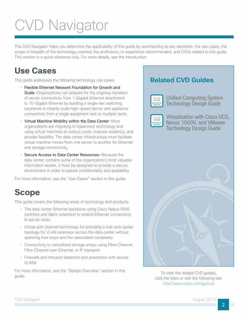
Use Casesthis guide addresses the following technology use cases:
• Flexible Ethernet Network Foundation for Growth and Scale—organizations can prepare for the ongoing transition of server connectivity from 1-gigabit ethernet attachment to 10-gigabit ethernet by building a single-tier switching backbone to cleanly scale high-speed server and appliance connectivity from a single equipment rack to multiple racks.
• Virtual Machine Mobility within the Data Center—Most organizations are migrating to hypervisor technology and using virtual machines to reduce costs, improve resiliency, and provide flexibility. the data center infrastructure must facilitate virtual machine moves from one server to another for ethernet and storage connectivity.
• Secure Access to Data Center Resources—Because the data center contains some of the organization’s most valuable information assets, it must be designed to provide a secure environment in order to assure confidentiality and availability.
For more information, see the “use Cases” section in this guide.
Scopethis guide covers the following areas of technology and products:
• the data center ethernet backbone using Cisco nexus 5500 switches and fabric extension to extend ethernet connectivity to server racks
• Virtual port channel technology for providing a hub-and-spoke topology for VlAn extension across the data center without spanning tree loops and the associated complexity
• Connectivity to centralized storage arrays using Fibre Channel, Fibre Channel over ethernet, or iP transport
• Firewalls and intrusion detection and prevention with secure VlAns
For more information, see the “Design overview” section in this guide.
Related CVD Guides
Uni�ed Computing SystemTechnology Design GuideVALIDATED
DESIGN
Virtualization with Cisco UCS,Nexus 1000V, and VMwareTechnology Design Guide
VALIDATEDDESIGN
to view the related CVD guides, click the titles or visit the following site:
http://www.cisco.com/go/cvd
CVD navigator August 20133
Proficiencythis guide is for people with the following technical proficiencies—or equivalent experience:
• CCNP Data Center—3 to 5 years designing, implementing, and troubleshooting data centers in all their components
• CCNP Routing and Switching—3 to 5 years planning, implementing, verifying, and troubleshooting local and wide-area networks
• CCNP Security—3 to 5 years testing, deploying, configuring, maintaining security appliances and other devices that establish the security posture of the network
introduction August 20134
introduction
Technology Use Casesorganizations encounter many challenges as they work to scale their information-processing capacity to keep up with demand. in a new organization, a small group of server resources may be sufficient to provide necessary applications such as file sharing, email, database applications, and web services. over time, demand for increased processing capacity, storage capacity, and distinct operational control over specific servers can cause a growth explosion commonly known as “server sprawl.”
server virtualization technologies help to more fully utilize the organization’s investment in processing capacity, while still allowing each virtual machine to be viewed independently from a security, configuration, and troubleshooting perspective. server virtualization and centralized storage technologies complement one another, allowing rapid deployment of new servers and reduced downtime in the event of server hardware failures. Virtual machines can be stored completely on the centralized storage system, which decouples the identity of the virtual machine from any single physical server. this allows the organization great flexibility when rolling out new applications or upgrading server hardware. in order to support the virtualization of computing resources in the data center, the underlying network must be able to provide a reliable, flexible, and secure transport.
Use Case: Flexible Ethernet Network Foundation for Growth and ScaleAs an organization outgrows the capacity of the basic server-room ethernet stack of switches, it is important to be prepared for the ongoing transition of server connectivity from 1-gigabit ethernet attachment to 10-gigabit ethernet. using a pair of Cisco nexus 5500 switches to form a single-tier of switching, this design provides the ability to cleanly scale high speed server and appliance connectivity from a single equipment rack to multiple racks, connected back to a pair of data center core switches.
this design guide enables the following network capabilities:
• High density rackmount server connectivity—servers in a data center rack need only be wired to the top of the rack where fabric extenders that connect to the data center core switches are located, for ethernet connectivity.
• Blade server system integration—Blade server systems requiring higher density 10-gigabit trunk connectivity can connect directly to the non-blocking data center core ethernet switches.
• Migration to high speed connectivity—in-rack ethernet connectivity to fabric extenders can accommodate the older Fast ethernet connections as well as 1-gigabit and 10-gigabit ethernet connectivity.
• Resilient core Ethernet—A pair of multiprotocol data center core ethernet switches provide sub-second failover in case of an unexpected outage.
• Simplified network configuration and operation—Configuration and monitoring of the data center ethernet is done centrally on the data center core switches.
• Server connectivity options—A single-homed, network adapter teaming, and etherChannel provide a wide range of options to connect a server to the data center ethernet.
introduction August 20135
Use Case: Virtual Machine Mobility within the Data Centerthe hypervisor technology provides the ability to cluster many virtual machines into a domain where workloads can be orchestrated to move around the data center to provide resiliency and load balancing.
this design guide enables the following network capabilities:
• VLANs can span the data center—Facilitates rapid installation of new servers and virtual machines without the need to redesign the network.
• Flexibility without spanning tree complexity—ethernet transport is extended to the data center racks with etherChannel in a hub-and-spoke design to avoid spanning tree loops and provide resilience.
• Centralized storage access—the network supports access over Fibre Channel, Fibre Channel over ethernet, and iP to centralized storage arrays to facilitate virtual machine moves from one server to another, as well as sAn boot.
Use Case: Secure Access to Data Center Resourcesthe data center contains some of the organization’s most valuable assets. Customer and personnel records, financial data, email stores, and intellectual property must be maintained in a secure environment in order to assure confidentiality and availability.
this design guide enables the following network capabilities:
• Secure server access—Firewall-protected VlAns to protect sensitive applications based on flexible rule-sets to protect from employee snooping or unauthorized access.
• Protect host resources from worms, viruses, and botnet attacks—Firewalls equipped with intrusion prevention system (iPs) sensors can configure protected VlAns to monitor and alert on abnormal traffic in a promiscuous intrusion detection system (iDs) mode, or to block malicious traffic before it reaches a destination server when deployed in inline iPs mode.
• High availability for protected VLANs—A pair of Cisco Adaptive security Appliance (AsA) 5585-X firewalls configured for active/standby operation ensure that access to the data center protected VlAns is minimally impacted by outages caused by software maintenance or hardware failure.
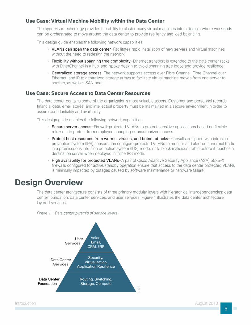
Design Overviewthe data center architecture consists of three primary modular layers with hierarchical interdependencies: data center foundation, data center services, and user services. Figure 1 illustrates the data center architecture layered services.
Figure 1 - Data center pyramid of service layers
21
96
UserServices
Data CenterServices
Data CenterFoundation
Voice,Email,
CRM, ERP
Security, Virtualization,
Application Resilience
Routing, Switching,Storage, Compute
introduction August 20136
the ultimate goal of the layers of the architecture is to support the user services that drive the organization’s success.
Data Center Foundationsimilar to the foundation of a building, the primary building block of the data center is the foundation layer upon which all other services rely. Whether it’s a server room ethernet lAn or a formal data center, the foundation must be resilient, scalable, and flexible in order to support data center services that add value, performance, and reliability. the data center foundation provides the computing necessary to support the applications that process information and the seamless transport between servers, storage, and the end users who access the applications.
to the applications and users, the network foundation works transparently when implemented correctly. the intelligent infrastructure of ethernet and storage switches tied to servers and storage arrays make this all possible.
Data Center ServicesData center services are the next layer in the hierarchy. like the customizable aspects of a building plan, they complement and customize the environment for the intended purpose. you may require large open spaces for a manufacturing floor, or high solid walls with controlled access for a secure environment. the consideration of these customizable services makes the structure more usable. Data center services allow you to customize the environment to a greater degree and enhance operation.
Cisco data center services include firewalls and intrusion prevention to enhance the security of the applications and access to critical data. Virtual switching extends the network control in a seamless manner from the foundation network into the hypervisor systems on servers to increase control and lower operational costs.
User Servicesuser services sit at the top of the pyramid and rely on the data center foundation and services to work. user services are those applications that allow a person to do their job and ultimately drive productivity for the organization. in the context of a building, this may be the elevator that takes you to your office floor, the lights in the office, or the message button on the phone that allows you to check messages. user services in the data center include email, order processing, and file sharing. other applications in the data center that rely on the data center foundation and services like data base applications, modeling, and transaction processing, also sit at the top of the pyramid of services.
introduction August 20137
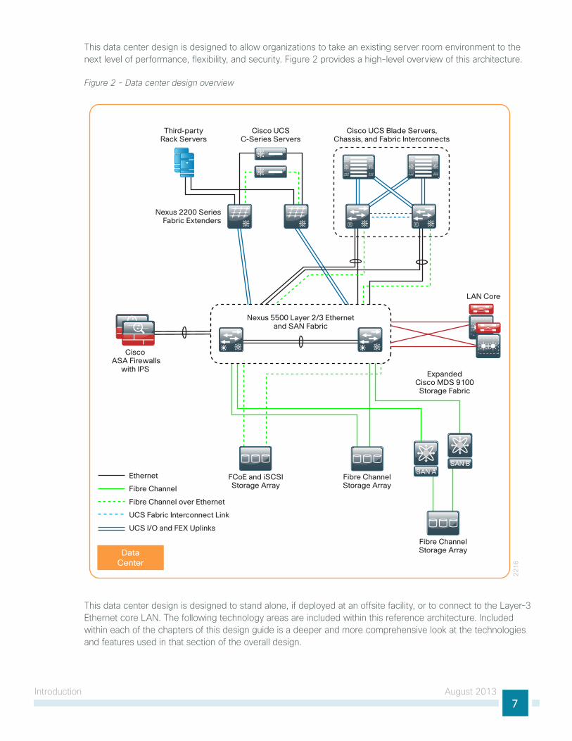
this data center design is designed to allow organizations to take an existing server room environment to the next level of performance, flexibility, and security. Figure 2 provides a high-level overview of this architecture.
Figure 2 - Data center design overview
22
16
Cisco ASA Firewalls
with IPS
Cisco UCSC-Series Servers
Cisco UCS Blade Servers, Chassis, and Fabric Interconnects
LAN Core
FCoE and iSCSIStorage Array
ExpandedCisco MDS 9100
Storage Fabric
Nexus 2200 SeriesFabric Extenders
Fibre ChannelStorage Array
Fibre ChannelStorage Array
SAN ASAN B
Nexus 5500 Layer 2/3 Ethernetand SAN Fabric
Third-partyRack Servers
SAN BSAN AEthernet
Fibre Channel
Fibre Channel over Ethernet
UCS Fabric Interconnect Link
UCS I/O and FEX Uplinks
DataCenter
this data center design is designed to stand alone, if deployed at an offsite facility, or to connect to the layer-3 ethernet core lAn. the following technology areas are included within this reference architecture. included within each of the chapters of this design guide is a deeper and more comprehensive look at the technologies and features used in that section of the overall design.
introduction August 20138
Ethernet Infrastructurethe ethernet infrastructure forms the foundation for resilient layer 2 and layer 3 communications in the data center. this layer provides the ability to migrate from your original server farm to a scalable architecture capable of supporting Fast ethernet, gigabit ethernet, and 10-gigabit ethernet connectivity for hundreds of servers in a modular approach.
the core of the data center is built on the Cisco nexus 5500uP series switches. Cisco nexus 5500uP series is a high-speed switch capable of layer 2 and layer 3 switching with the layer 3 daughter card tested in this design. Cisco nexus 5500uP series 48-port and 96-port models are suitable for use in this design based on data center port density requirements. Cisco nexus 5500uP supports Fabric extender (FeX) technology, which provides a remote line card approach for fan out of server connectivity to top of rack for Fast ethernet, gigabit ethernet, and 10-gigabit ethernet requirements. the physical interfaces on the Cisco FeX are programmed on the Cisco nexus 5500uP switches, simplifying the task of configuration by reducing the number of devices you have to touch to deploy a server port.
the Cisco nexus 5500uP series features Virtual Port Channel (vPC) technology, which provides a loop-free approach to building out the data center in which any VlAn can appear on any port in the topology without spanning-tree loops or blocking links. the data center core switches are redundant with sub-second failover so that a device failure or maintenance does not prevent the network from operating.
Storage Infrastructurestorage networking is key to solving the growing amount of data storage that an organization has to struggle with. Centralized storage reduces the amount of disk space trapped on individual server platforms and eases the task of providing backup to avoid data loss. the data center design uses Cisco nexus 5500uP series switches as the core of the network. the importance of this model switch is that it has universal port (uP) capabilities. A universal port is capable of supporting ethernet, Fibre Channel, and Fibre Channel over ethernet (FCoe) on any port. this allows the data center core to support multiple storage networking technologies like Fibre Channel storage area network (sAn), internet small Computer system interface (isCsi), and network attached storage (nAs) on a single platform type. this not only reduces costs to deploy the network but saves rack space in expensive data center hosting environments.
Cisco nexus 5500uP Fibre Channel capabilities are based on the Cisco nX-os operating system and seamlessly interoperate with the Cisco MDs series sAn switches for higher-capacity Fibre Channel requirements. this chapter includes procedures for interconnecting between Cisco nexus 5500uP series and Cisco MDs series for Fibre Channel sAn. Cisco MDs series can provide an array of advanced services for Fibre Channel sAn environments where high-speed encryption, inter-VsAn routing, tape services, or Fibre Channel over iP extension might be required.
Compute Connectivitythere are many ways to connect a server to the data center network for ethernet and Fibre Channel transport. this chapter provides an overview of connectivity ranging from single-homed ethernet servers to a dual-homed Fabric extender, and dual-homed servers that might use active/standby network interface card (niC) teaming or etherChannel for resiliency. servers that use 10-gigabit ethernet can collapse multiple ethernet niCs and Fibre Channel host bus adapters (hBAs) onto a single wire using converged network adapters (CnAs) and FCoe. Dual-homing the 10-gigabit ethernet servers with FCoe provides resilient ethernet transport and Fibre Channel connections to sAn-A/sAn-B topologies. this chapter also provides an overview of how the integrated connectivity of Cisco unified Computing system (uCs) blade server systems work and considerations for connecting a non–Cisco blade server system to the network.
introduction August 20139
Network SecurityWithin a data center design, there are many requirements and opportunities to include or improve security for customer confidential information and the organization’s critical and sensitive applications. the data center design is tested with the Cisco AsA 5585-X series firewall. Cisco AsA 5585-X provides high-speed processing for firewall rule sets and high bandwidth connectivity with multiple 10-gigabit ethernet ports for resilient connectivity to the data center core switches. Cisco AsA 5585-X also has a slot for services, and in this design provides an iPs module to inspect application layer data, to detect attacks and snooping, and to block malicious traffic based on the content of the packet or the reputation of the sender. the Cisco AsA 5585-X firewalls with iPs modules are deployed in a pair, which provides an active/standby resiliency to prevent downtime in the event of a failure or platform maintenance.
Physical environment August 201310
Physical environment
Design Overviewthis data center design provides a resilient environment with redundant platforms and links; however, this cannot protect your data center from a complete failure resulting from a total loss of power or cooling. When designing your data center, you must consider how much power you will require, how you will provide backup power in the event of a loss of your power feed from your provider, and how long you will retain power in a backup power event. you also need to consider that servers, networking equipment, and appliances in your data center dissipate heat as they operate, which requires that you develop a proper cooling design that includes locating equipment racks to prevent hotspots.
PowerKnow what equipment will be installed in the area. you cannot plan electrical work if you do not know what equipment is going to be used. some equipment requires standard 110V outlets that may already be available. other equipment might require much more power.
Does the power need to be on all the time? in most cases where servers and storage are involved, the answer is yes. Applications don’t react very well when the power goes out. to prevent power outages, you need an uninterruptable power supply (uPs). During a power interruption, the uPs will switch over the current load to a set of internal or external batteries. some uPss are online, which means the power is filtered through the batteries all the time; others are switchable, meaning they use batteries only during power loss. uPss vary by how much load they can carry and for how long. Careful planning is required to make sure the correct uPs is purchased, installed, and managed correctly. Most uPss provide for remote monitoring and the ability to trigger a graceful server shutdown for critical servers if the uPs is going to run out of battery.
Distributing the power to the equipment can change the power requirements as well. there are many options available to distribute the power from the outlet or uPs to the equipment. one example would be using a power strip that resides vertically in a cabinet that usually has an l6-30 input and then C13/C19 outlets with the output voltage in the 200–240V range. these strips should be—at a minimum—metered so one does not overload the circuits. the meter provides a current reading of the load on the circuit. this is critical, because a circuit breaker that trips due to being overloaded will bring down everything plugged into it with no warning, causing business downtime and possible data loss. For complete remote control, power strips are available with full remote control of each individual outlet from a web browser. these vertical strips also assist in proper cable management of the power cords. short C13/C14 and C19/C20 power cords can be used instead of much longer cords to multiple 110V outlets or multiple 110V power strips.
CoolingWith power comes the inevitable conversion of power into heat. to put it simply: power in equals heat out. Planning for cooling of one or two servers and a switch with standard building air conditioning may work. Multiple servers and blade servers (along with storage, switches, etc.) need more than building air conditioning for proper cooling. Be sure to at least plan with your facilities team what the options are for current and future cooling. Many options are available, including in-row cooling, overhead cooling, raised floor with underfloor cooling, and wall-mounted cooling.
Physical environment August 201311
Equipment Rackingit’s important to plan where to put the equipment. Proper placement and planning allow for easy growth. After you have evaluated power and cooling, you need to install racking or cabinets. servers tend to be fairly deep and take up even more space with their network connections and power connections. Most servers will fit in a 42-inch deep cabinet, and deeper cabinets give more flexibility for cable and power management within the cabinet. Be aware of what rails are required by your servers. Most servers now come with rack mounts that use the square hole–style vertical cabinet rails. not having the proper rails can mean that you have to use adapters or shelves, which makes managing servers and equipment difficult if not sometimes impossible without removing other equipment or sacrificing space. Data center racks should use the square rail mounting options in the cabinets. Cage nuts can be used to provide threaded mounts for such things as routers, switches, shelves, etc. that you may need.
Summarythe physical environmental requirements for a data center require careful planning to provide for efficient use of space, scalability, and ease of operational maintenance. For additional information on data center power, cooling, and equipment racking, contact Cisco partners in the area of data center environmental products such as Panduit and APC.
ethernet infrastructure August 201312
ethernet infrastructure
Design Overviewthe foundation of the ethernet network in this data center design is a resilient pair of Cisco nexus 5500uP series switches. these switches offer the ideal platform for building a scalable, high-performance data center supporting both 10-gigabit and 1-gigabit ethernet attached servers. the data center is designed to allow easy migration of servers and services from your original server room to a data center that can scale with your organization’s growth.
the Cisco nexus 5500uP switches with universal port (uP) capabilities provide support for ethernet, Fibre Channel over ethernet (FCoe), and Fibre Channel ports on a single platform. the nexus 5500uP can act as the Fibre Channel sAn for the data center and connect into an existing Fibre Channel sAn. the Cisco nexus 5000 series also supports the Cisco nexus 2000 series Fabric extenders. Fabric extenders allow the switching fabric of the resilient switching pair to be physically extended to provide port aggregation in the top of multiple racks, reducing cable management issues as the server environment expands.
this data center design leverages many advanced features of the Cisco nexus 5500uP series switch family to provide a central layer 2 and layer 3 switching fabric for the data center environment:
• the layer 3 routing table can accommodate up to 8000 iPv4 routes.
• the layer 3 engine supports up to 8000 adjacencies or MAC addresses for the layer 2 domain.
• the solution provides for up to 1000 iP Multicast groups when operating in the recommended Virtual Port Channel (vPC) mode.
A second generation of the layer 3 engine for the Cisco nexus 5548 and 5596 switches is now available. this second generation hardware version of the layer 3 module doubles the scalability for routing and adjacencies when you are running Cisco nX-os software release 5.2(1)n1(1) or later.
More specific scalability design numbers for the Cisco nexus 5500 series platform can be found at:
http://www.cisco.com/en/us/docs/switches/datacenter/nexus5000/sw/configuration_limits/limits_521/nexus_5000_config_limits_521.html
Reader Tip
ethernet infrastructure August 201313
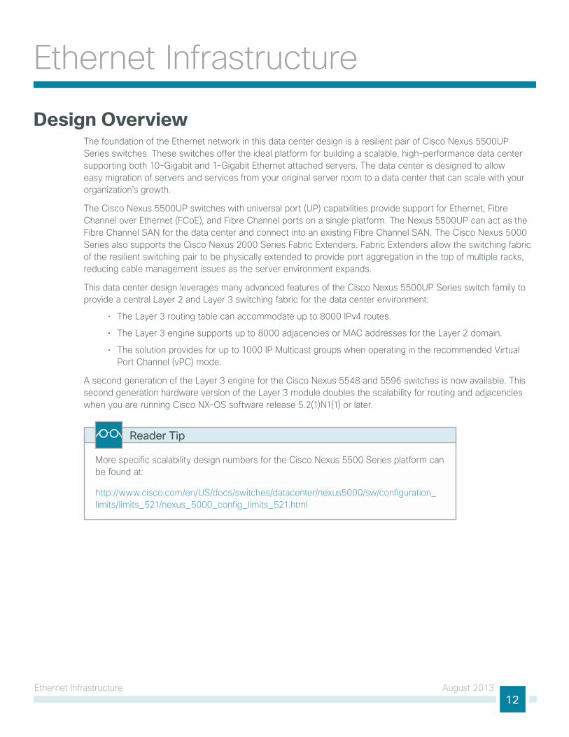
the layer 3 data center core connects to the layer 3 lAn core as shown in Figure 3.
Figure 3 - Data center core and LAN core change control separation
Data Center Serversand Services
21
98LAN Internet
and DMZWAN
DataCenterCore
SeparateChange Control
Domains
LAN Core
the result of using layer 3 to interconnect the two core layers is:
• A resilient layer 3 interconnect with rapid failover.
• A logical separation of change control for the two core networks.
• A lAn core that provides a scalable interconnect for lAn, WAn, and internet edge.
• A data center core that provides interconnect for all data center servers and services.
• intra-data center layer 2 and layer 3 traffic flows between servers and appliances that are switched locally on the data center core.
• A data center that has a logical separation point for moving to an offsite location while still providing core services without redesign.
this section provides an overview of the key features used in this topology and illustrates the specific physical connectivity that applies to the example configurations provided in the “Deployment Details” section.
ethernet infrastructure August 201314
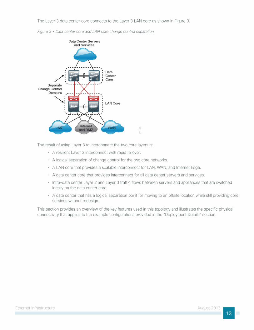
Resilient Data Center Corethe data center needs to provide a topology where any data center VlAn can be extended to any server in the environment to accommodate new installations without disruption, and also the ability to move a server load to any other physical server in the data center. traditional layer 2 designs with lAn switches use spanning tree, which creates loops when a VlAn is extended to multiple access layer switches. spanning tree Protocol blocks links to prevent looping, as shown in Figure 4.
Figure 4 - Traditional design with spanning tree blocked links
20
52
Spanning TreeBlocked Link
Spanning TreeRoot Switch
VLAN 148 VLAN 148
the Cisco nexus 5500uP series switch pair providing the central ethernet switching fabric for the data center is configured using vPC. the vPC feature allows links that are physically connected to two different Cisco nexus switches to appear to a third downstream device to be coming from a single device, as part of a single ethernet port channel. the third device can be a server, switch, or any other device or appliance that supports ieee 802.3ad port channels. this capability allows the two data center core switches to build resilient, loop-free layer 2 topologies that forward on all connected links instead of requiring spanning tree Protocol blocking for loop prevention.
Cisco nX-os software vPC used in the data center design and Cisco Catalyst Virtual switching systems (Vss) used in lAn deployments are similar technologies in that they allow the creation of layer 2 port channels that span two switches. For Cisco etherChannel technology, the term multichassis EtherChannel (MCeC) refers to either technology interchangeably. MCeC links from a device connected using vPC to the data center core and provides spanning-tree loop–free topologies, allowing VlAns to be extended across the data center while maintaining a resilient architecture.
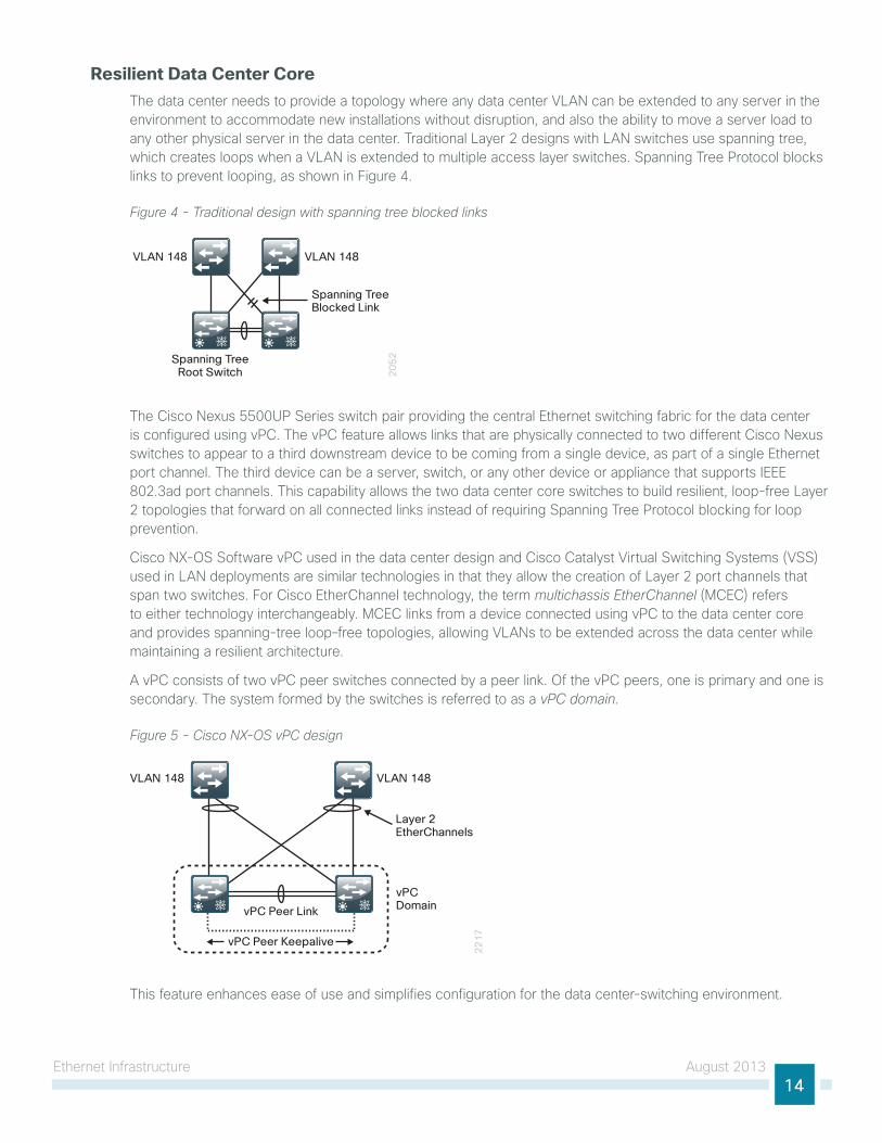
A vPC consists of two vPC peer switches connected by a peer link. of the vPC peers, one is primary and one is secondary. the system formed by the switches is referred to as a vPC domain.
Figure 5 - Cisco NX-OS vPC design
22
17
Layer 2EtherChannels
vPC Peer Keepalive
vPC Peer Link
VLAN 148 VLAN 148
vPCDomain
this feature enhances ease of use and simplifies configuration for the data center-switching environment.
ethernet infrastructure August 201315
For more information on vPC technology and design, refer to the documents “Cisco nX-os software Virtual PortChannel: Fundamental Concepts” and “spanning-tree Design guidelines for Cisco nX-os software and Virtual PortChannels,” here:
http://www.cisco.com/en/us/prod/collateral/switches/ps9441/ps9670/C07-572835-00_nX-os_vPC_Dg.pdf
Reader Tip
this data center design uses hot standby Router Protocol (hsRP) for iP default gateway resiliency for data center VlAns. When combining hsRP with vPC, there is no need for aggressive hsRP timers to improve convergence, because both gateways are always active and traffic to either data center core will be locally switched for improved performance and resiliency.
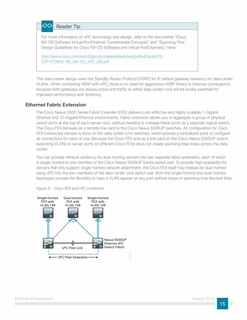
Ethernet Fabric Extensionthe Cisco nexus 2000 series Fabric extender (FeX) delivers cost-effective and highly scalable 1-gigabit ethernet and 10-gigabit ethernet environments. Fabric extension allows you to aggregate a group of physical switch ports at the top of each server rack, without needing to manage these ports as a separate logical switch. the Cisco FeX behaves as a remote line card to the Cisco nexus 5500uP switches. All configuration for Cisco FeX–connected servers is done on the data center core switches, which provide a centralized point to configure all connections for ease of use. Because the Cisco FeX acts as a line card on the Cisco nexus 5500uP switch, extending VlAns to server ports on different Cisco FeXs does not create spanning-tree loops across the data center.
you can provide network resiliency by dual-homing servers into two separate fabric extenders, each of which is single-homed to one member of the Cisco nexus 5500uP series switch pair. to provide high availability for servers that only support single-homed network attachment, the Cisco FeX itself may instead be dual-homed using vPC into the two members of the data center core switch pair. Both the single-homed and dual-homed topologies provide the flexibility to have a VlAn appear on any port without loops or spanning-tree blocked links.
Figure 6 - Cisco FEX and vPC combined
22
18
vPC Peer Keepalive
vPC Peer Link
Single-homedFEX with
VLAN 148
Dual-homedFEX with
VLAN 148
Single-homedFEX with
VLAN 148
Nexus 5500UPEthernet vPCSwitch Fabric
ethernet infrastructure August 201316
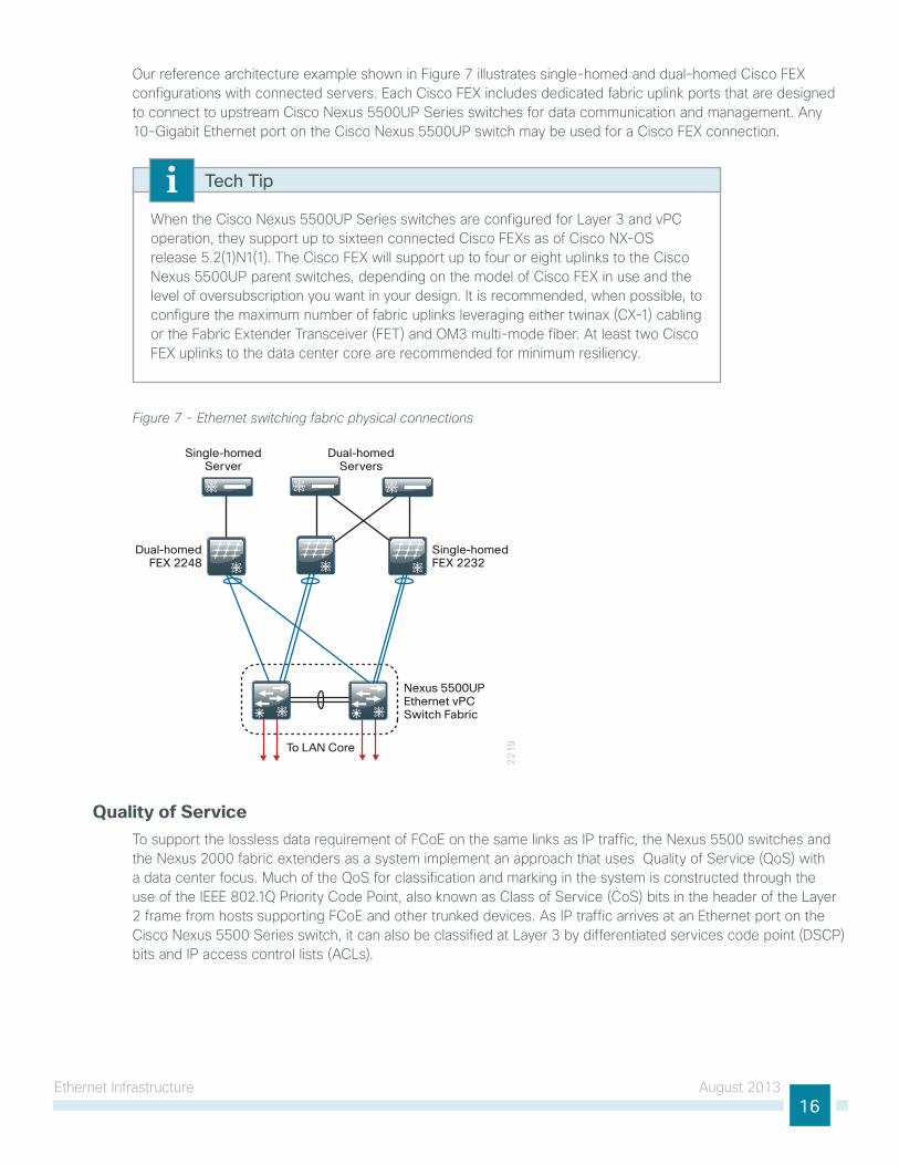
our reference architecture example shown in Figure 7 illustrates single-homed and dual-homed Cisco FeX configurations with connected servers. each Cisco FeX includes dedicated fabric uplink ports that are designed to connect to upstream Cisco nexus 5500uP series switches for data communication and management. Any 10-gigabit ethernet port on the Cisco nexus 5500uP switch may be used for a Cisco FeX connection.
When the Cisco nexus 5500uP series switches are configured for layer 3 and vPC operation, they support up to sixteen connected Cisco FeXs as of Cisco nX-os release 5.2(1)n1(1). the Cisco FeX will support up to four or eight uplinks to the Cisco nexus 5500uP parent switches, depending on the model of Cisco FeX in use and the level of oversubscription you want in your design. it is recommended, when possible, to configure the maximum number of fabric uplinks leveraging either twinax (CX-1) cabling or the Fabric extender transceiver (Fet) and oM3 multi-mode fiber. At least two Cisco FeX uplinks to the data center core are recommended for minimum resiliency.
Tech Tip
Figure 7 - Ethernet switching fabric physical connections
22
19To LAN Core
Dual-homedFEX 2248
Single-homedFEX 2232
Dual-homedServers
Single-homedServer
Nexus 5500UPEthernet vPCSwitch Fabric
Quality of Serviceto support the lossless data requirement of FCoe on the same links as iP traffic, the nexus 5500 switches and the nexus 2000 fabric extenders as a system implement an approach that uses Quality of service (Qos) with a data center focus. Much of the Qos for classification and marking in the system is constructed through the use of the ieee 802.1Q Priority Code Point, also known as Class of service (Cos) bits in the header of the layer 2 frame from hosts supporting FCoe and other trunked devices. As iP traffic arrives at an ethernet port on the Cisco nexus 5500 series switch, it can also be classified at layer 3 by differentiated services code point (DsCP) bits and iP access control lists (ACls).
ethernet infrastructure August 201317
the traffic classifications are used for mapping traffic into one of six hardware queues, each appropriately configured for desired traffic handling. one queue is predefined for default traffic treatment, while one hardware queue is assigned for use by lossless FCoe traffic. the remaining four queues are available for use to support queuing of multimedia and data center traffic. For example, a priority queue will be defined for jitter-intolerant multimedia services in the data center.
lacking the guarantee that all non-FCoe devices in the data center can generate an appropriate Cos marking required for application of Qos policy at ingress to a FeX, this data center design takes the following Qos approach:
• FCoe traffic, as determined by Data Center Bridging exchange (DCBX) negotiation with hosts, is given priority and lossless treatment end-to-end within the data center.
• non-FCoe traffic without Cos classification for devices connected to a FeX is given default treatment over available links on ingress toward the Cisco nexus 5500 switch, with suitable aggregated link bandwidth available to mitigate oversubscription situations. traffic in the reverse direction toward the FeX is handled by the Qos egress policies on the Cisco nexus 5500 switch.
• Classification by DsCP is configured at the port level and applied to iP traffic on ingress to the Cisco nexus 5500 switch, either directly or after traversing a FeX connection. this classification is used to map traffic into the default queue or into one of the four non-FCoe internal queues to offer a suitable Qos per-hop behavior.
• to ensure consistent policy treatment for traffic directed through the layer 3 engine, a Cos marking is also applied per Cisco nexus 5500 internal queue. the Cos marking is used for classification of traffic ingress to the layer 3 engine, allowing application of system queuing policies.
non-FCoe devices requiring DsCP-based classification with guaranteed queuing treatment can be connected directly to the Cisco nexus 5500 switch, versus taking the default uplink treatment when connected to a Cisco FeX port.
the Qos policy is also the method for configuring jumbo frame support on a per-class basis. Consistent per-Cos maximum transmission unit (Mtu) requirements are applied system-wide for FCoe, as opposed to the port-based Mtu configuration typical of devices used outside of the data center. increasing Mtu size can increase performance for bulk data transfers.
ethernet infrastructure August 201318
Deployment Detailsthe following configuration procedures are required to configure the ethernet switching fabric for this data center design.
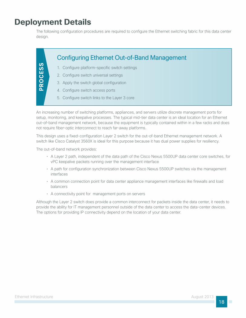
Configuring Ethernet Out-of-Band Management
1. Configure platform-specific switch settings
2. Configure switch universal settings
3. Apply the switch global configuration
4. Configure switch access ports
5. Configure switch links to the layer 3 core
PR
OC
ESS
An increasing number of switching platforms, appliances, and servers utilize discrete management ports for setup, monitoring, and keepalive processes. the typical mid-tier data center is an ideal location for an ethernet out-of-band management network, because the equipment is typically contained within in a few racks and does not require fiber-optic interconnect to reach far-away platforms.
this design uses a fixed-configuration layer 2 switch for the out-of-band ethernet management network. A switch like Cisco Catalyst 3560X is ideal for this purpose because it has dual power supplies for resiliency.
the out-of-band network provides:
• A layer 2 path, independent of the data path of the Cisco nexus 5500uP data center core switches, for vPC keepalive packets running over the management interface
• A path for configuration synchronization between Cisco nexus 5500uP switches via the management interfaces
• A common connection point for data center appliance management interfaces like firewalls and load balancers
• A connectivity point for management ports on servers
Although the layer 2 switch does provide a common interconnect for packets inside the data center, it needs to provide the ability for it management personnel outside of the data center to access the data-center devices. the options for providing iP connectivity depend on the location of your data center.
ethernet infrastructure August 201319
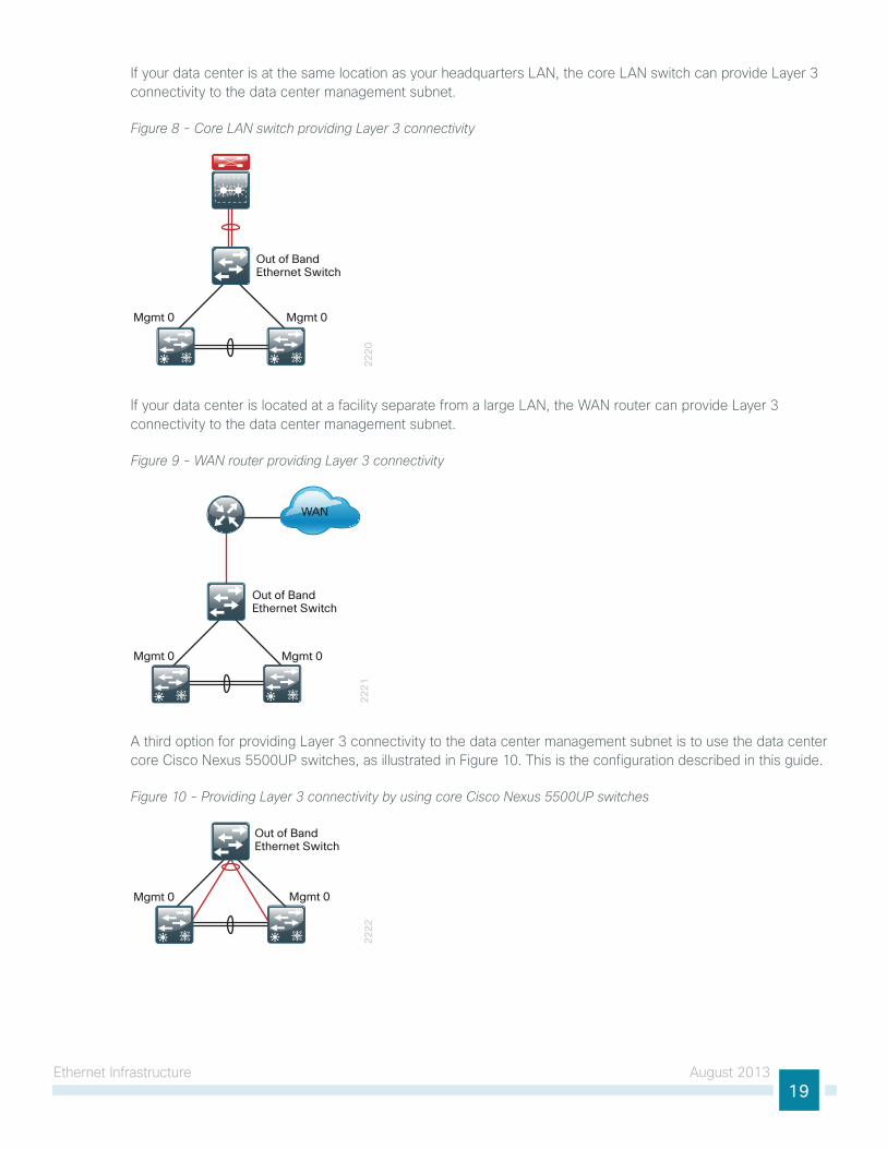
if your data center is at the same location as your headquarters lAn, the core lAn switch can provide layer 3 connectivity to the data center management subnet.
Figure 8 - Core LAN switch providing Layer 3 connectivity
22
20
Mgmt 0 Mgmt 0
Out of BandEthernet Switch
if your data center is located at a facility separate from a large lAn, the WAn router can provide layer 3 connectivity to the data center management subnet.
Figure 9 - WAN router providing Layer 3 connectivity
22
21
Mgmt 0 Mgmt 0
Out of BandEthernet Switch
WAN
A third option for providing layer 3 connectivity to the data center management subnet is to use the data center core Cisco nexus 5500uP switches, as illustrated in Figure 10. this is the configuration described in this guide.
Figure 10 - Providing Layer 3 connectivity by using core Cisco Nexus 5500UP switches
22
22
Mgmt 0 Mgmt 0
Out of BandEthernet Switch
ethernet infrastructure August 201320
When you use the data center core Cisco nexus 5500uP switches for layer 3 connectivity, the layer 2 path for vPC keepalive packets will use the ethernet out-of-band switch, because the nexus 5500uP management ports are in a separate management Virtual Routing and Forwarding (VRF) path than the global packet switching of the Cisco nexus 5500uP switches. Also, the management ports are in the same iP subnet, so they do not need a layer 3 switch for packets between the data center core switches. the layer 3 switched virtual interface (sVi) will provide connectivity for access outside of the data center.
Tech Tip
Procedure 1 Configure platform-specific switch settings
Step 1: Configure the Catalyst 2960-s and 3750-X platform.
switch [switch number] priority 15
When there are multiple Cisco Catalyst 2960-s or Cisco Catalyst 3750-X series switches configured in a stack, one of the switches controls the operation of the stack and is called the stack master.
When three or more switches are configured in a stack, choose a switch that does not have uplinks configured to configure as the stack master.
Step 2: ensure the original master MAC address remains the stack MAC address after a failure.
stack-mac persistent timer 0
the default behavior when the stack master switch fails is for the newly active stack master switch to assign a new stack MAC address. this new MAC address assignment can cause the network to have to reconverge, because link Aggregation Control Protocol (lACP) and many other protocols rely on the stack MAC address and must restart. As such, the stack-mac persistent timer 0 command should be used to ensure that the original master MAC address remains the stack MAC address after a failure.
Because AutoQos may not be configured on this device, you need to manually configure the global Qos settings by defining a macro that you will use in later procedures to apply the platform-specific Qos configuration.
ethernet infrastructure August 201321
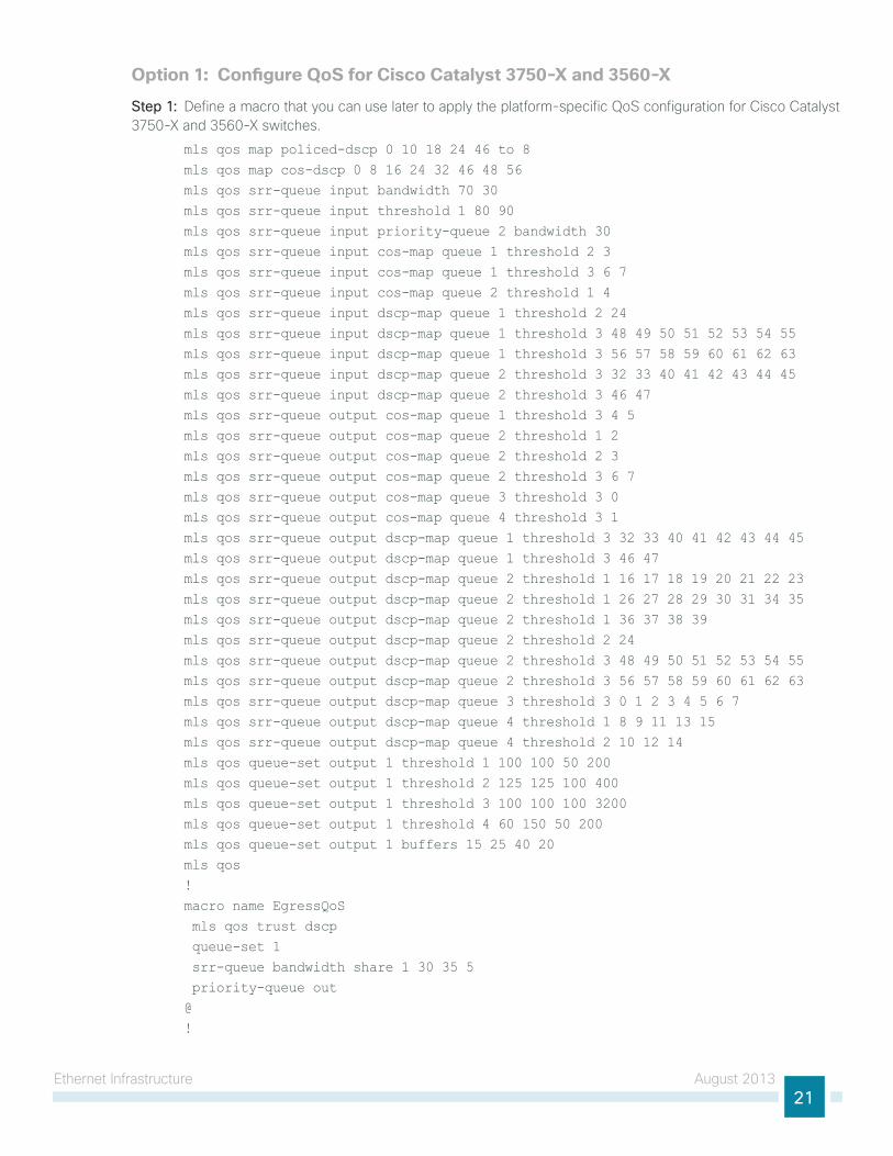
Option 1: Configure QoS for Cisco Catalyst 3750-X and 3560-X
Step 1: Define a macro that you can use later to apply the platform-specific Qos configuration for Cisco Catalyst 3750-X and 3560-X switches.
mls qos map policed-dscp 0 10 18 24 46 to 8 mls qos map cos-dscp 0 8 16 24 32 46 48 56 mls qos srr-queue input bandwidth 70 30 mls qos srr-queue input threshold 1 80 90 mls qos srr-queue input priority-queue 2 bandwidth 30 mls qos srr-queue input cos-map queue 1 threshold 2 3 mls qos srr-queue input cos-map queue 1 threshold 3 6 7 mls qos srr-queue input cos-map queue 2 threshold 1 4 mls qos srr-queue input dscp-map queue 1 threshold 2 24 mls qos srr-queue input dscp-map queue 1 threshold 3 48 49 50 51 52 53 54 55 mls qos srr-queue input dscp-map queue 1 threshold 3 56 57 58 59 60 61 62 63 mls qos srr-queue input dscp-map queue 2 threshold 3 32 33 40 41 42 43 44 45 mls qos srr-queue input dscp-map queue 2 threshold 3 46 47 mls qos srr-queue output cos-map queue 1 threshold 3 4 5 mls qos srr-queue output cos-map queue 2 threshold 1 2 mls qos srr-queue output cos-map queue 2 threshold 2 3 mls qos srr-queue output cos-map queue 2 threshold 3 6 7 mls qos srr-queue output cos-map queue 3 threshold 3 0 mls qos srr-queue output cos-map queue 4 threshold 3 1 mls qos srr-queue output dscp-map queue 1 threshold 3 32 33 40 41 42 43 44 45 mls qos srr-queue output dscp-map queue 1 threshold 3 46 47 mls qos srr-queue output dscp-map queue 2 threshold 1 16 17 18 19 20 21 22 23 mls qos srr-queue output dscp-map queue 2 threshold 1 26 27 28 29 30 31 34 35 mls qos srr-queue output dscp-map queue 2 threshold 1 36 37 38 39 mls qos srr-queue output dscp-map queue 2 threshold 2 24 mls qos srr-queue output dscp-map queue 2 threshold 3 48 49 50 51 52 53 54 55 mls qos srr-queue output dscp-map queue 2 threshold 3 56 57 58 59 60 61 62 63 mls qos srr-queue output dscp-map queue 3 threshold 3 0 1 2 3 4 5 6 7 mls qos srr-queue output dscp-map queue 4 threshold 1 8 9 11 13 15 mls qos srr-queue output dscp-map queue 4 threshold 2 10 12 14 mls qos queue-set output 1 threshold 1 100 100 50 200 mls qos queue-set output 1 threshold 2 125 125 100 400 mls qos queue-set output 1 threshold 3 100 100 100 3200 mls qos queue-set output 1 threshold 4 60 150 50 200 mls qos queue-set output 1 buffers 15 25 40 20 mls qos !macro name EgressQoS mls qos trust dscp queue-set 1 srr-queue bandwidth share 1 30 35 5 priority-queue out@!

ethernet infrastructure August 201322
Option 2: Configure QoS for Cisco Catalyst 2960-S
Step 1: Define a macro that you can use later to apply the platform-specific Qos configuration for Cisco Catalyst 2960-s switches.
mls qos map policed-dscp 0 10 18 24 46 to 8
mls qos map cos-dscp 0 8 16 24 32 46 48 56
mls qos srr-queue output cos-map queue 1 threshold 3 4 5
mls qos srr-queue output cos-map queue 2 threshold 1 2
mls qos srr-queue output cos-map queue 2 threshold 2 3
mls qos srr-queue output cos-map queue 2 threshold 3 6 7
mls qos srr-queue output cos-map queue 3 threshold 3 0
mls qos srr-queue output cos-map queue 4 threshold 3 1
mls qos srr-queue output dscp-map queue 1 threshold 3 32 33 40 41 42 43 44 45
mls qos srr-queue output dscp-map queue 1 threshold 3 46 47
mls qos srr-queue output dscp-map queue 2 threshold 1 16 17 18 19 20 21 22 23
mls qos srr-queue output dscp-map queue 2 threshold 1 26 27 28 29 30 31 34 35
mls qos srr-queue output dscp-map queue 2 threshold 1 36 37 38 39
mls qos srr-queue output dscp-map queue 2 threshold 2 24
mls qos srr-queue output dscp-map queue 2 threshold 3 48 49 50 51 52 53 54 55
mls qos srr-queue output dscp-map queue 2 threshold 3 56 57 58 59 60 61 62 63
mls qos srr-queue output dscp-map queue 3 threshold 3 0 1 2 3 4 5 6 7
mls qos srr-queue output dscp-map queue 4 threshold 1 8 9 11 13 15
mls qos srr-queue output dscp-map queue 4 threshold 2 10 12 14
mls qos queue-set output 1 threshold 1 100 100 50 200
mls qos queue-set output 1 threshold 2 125 125 100 400
mls qos queue-set output 1 threshold 3 100 100 100 3200
mls qos queue-set output 1 threshold 4 60 150 50 200
mls qos queue-set output 1 buffers 15 25 40 20
mls qos
!
macro name EgressQoS
mls qos trust dscp
queue-set 1
srr-queue bandwidth share 1 30 35 5
priority-queue out
@
!
ethernet infrastructure August 201323
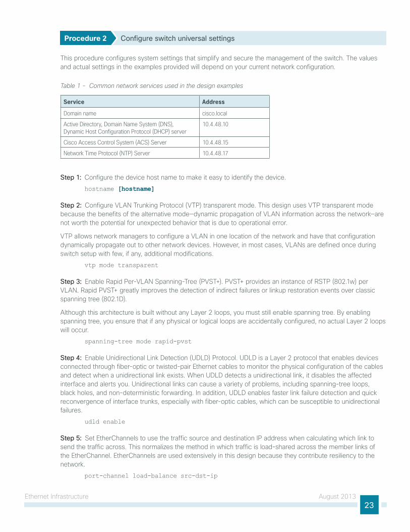
Procedure 2 Configure switch universal settings
this procedure configures system settings that simplify and secure the management of the switch. the values and actual settings in the examples provided will depend on your current network configuration.
Table 1 - Common network services used in the design examples
Service Address
Domain name cisco.local
Active Directory, Domain Name System (DNS), Dynamic Host Configuration Protocol (DHCP) server
10.4.48.10
Cisco Access Control System (ACS) Server 10.4.48.15
Network Time Protocol (NTP) Server 10.4.48.17
Step 1: Configure the device host name to make it easy to identify the device.
hostname [hostname]
Step 2: Configure VlAn trunking Protocol (VtP) transparent mode. this design uses VtP transparent mode because the benefits of the alternative mode—dynamic propagation of VlAn information across the network—are not worth the potential for unexpected behavior that is due to operational error.
VtP allows network managers to configure a VlAn in one location of the network and have that configuration dynamically propagate out to other network devices. however, in most cases, VlAns are defined once during switch setup with few, if any, additional modifications.
vtp mode transparent
Step 3: enable Rapid Per-VlAn spanning-tree (PVst+). PVst+ provides an instance of RstP (802.1w) per VlAn. Rapid PVst+ greatly improves the detection of indirect failures or linkup restoration events over classic spanning tree (802.1D).
Although this architecture is built without any layer 2 loops, you must still enable spanning tree. By enabling spanning tree, you ensure that if any physical or logical loops are accidentally configured, no actual layer 2 loops will occur.
spanning-tree mode rapid-pvst
Step 4: enable unidirectional link Detection (uDlD) Protocol. uDlD is a layer 2 protocol that enables devices connected through fiber-optic or twisted-pair ethernet cables to monitor the physical configuration of the cables and detect when a unidirectional link exists. When uDlD detects a unidirectional link, it disables the affected interface and alerts you. unidirectional links can cause a variety of problems, including spanning-tree loops, black holes, and non-deterministic forwarding. in addition, uDlD enables faster link failure detection and quick reconvergence of interface trunks, especially with fiber-optic cables, which can be susceptible to unidirectional failures.
udld enable
Step 5: set etherChannels to use the traffic source and destination iP address when calculating which link to send the traffic across. this normalizes the method in which traffic is load-shared across the member links of the etherChannel. etherChannels are used extensively in this design because they contribute resiliency to the network.
port-channel load-balance src-dst-ip
ethernet infrastructure August 201324
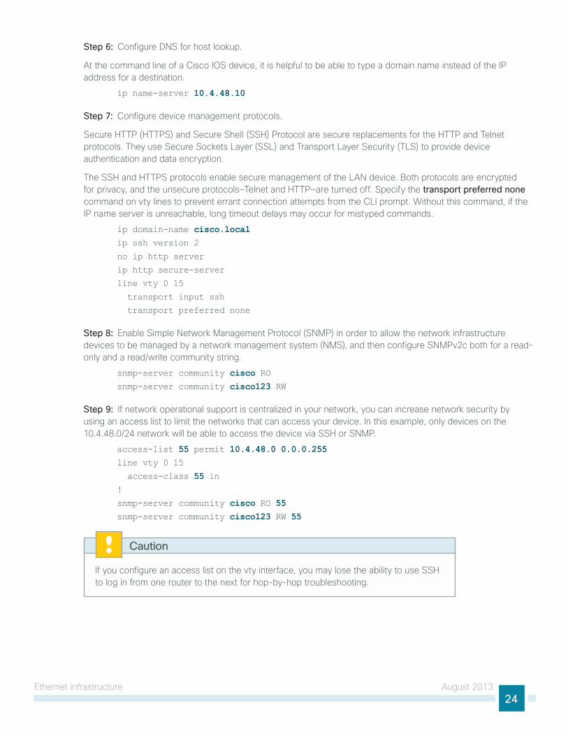
Step 6: Configure Dns for host lookup.
At the command line of a Cisco ios device, it is helpful to be able to type a domain name instead of the iP address for a destination.
ip name-server 10.4.48.10
Step 7: Configure device management protocols.
secure httP (httPs) and secure shell (ssh) Protocol are secure replacements for the httP and telnet protocols. they use secure sockets layer (ssl) and transport layer security (tls) to provide device authentication and data encryption.
the ssh and httPs protocols enable secure management of the lAn device. Both protocols are encrypted for privacy, and the unsecure protocols—telnet and httP—are turned off. specify the transport preferred none command on vty lines to prevent errant connection attempts from the Cli prompt. Without this command, if the iP name server is unreachable, long timeout delays may occur for mistyped commands.
ip domain-name cisco.localip ssh version 2
no ip http server
ip http secure-server
line vty 0 15
transport input ssh
transport preferred none
Step 8: enable simple network Management Protocol (snMP) in order to allow the network infrastructure devices to be managed by a network management system (nMs), and then configure snMPv2c both for a read-only and a read/write community string.
snmp-server community cisco RO snmp-server community cisco123 RW
Step 9: if network operational support is centralized in your network, you can increase network security by using an access list to limit the networks that can access your device. in this example, only devices on the 10.4.48.0/24 network will be able to access the device via ssh or snMP.
access-list 55 permit 10.4.48.0 0.0.0.255line vty 0 15
access-class 55 in !
snmp-server community cisco RO 55 snmp-server community cisco123 RW 55
if you configure an access list on the vty interface, you may lose the ability to use ssh to log in from one router to the next for hop-by-hop troubleshooting.
Caution
ethernet infrastructure August 201325
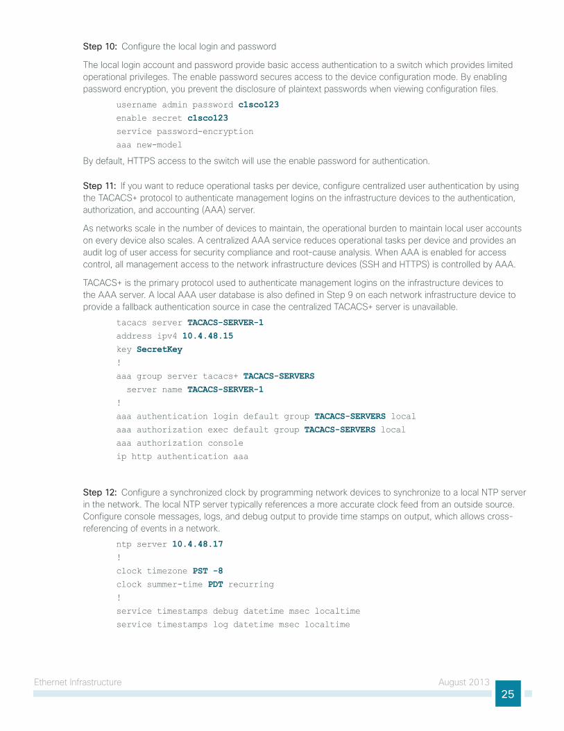
Step 10: Configure the local login and password
the local login account and password provide basic access authentication to a switch which provides limited operational privileges. the enable password secures access to the device configuration mode. By enabling password encryption, you prevent the disclosure of plaintext passwords when viewing configuration files.
username admin password c1sco123enable secret c1sco123service password-encryption
aaa new-model
By default, httPs access to the switch will use the enable password for authentication.
Step 11: if you want to reduce operational tasks per device, configure centralized user authentication by using the tACACs+ protocol to authenticate management logins on the infrastructure devices to the authentication, authorization, and accounting (AAA) server.
As networks scale in the number of devices to maintain, the operational burden to maintain local user accounts on every device also scales. A centralized AAA service reduces operational tasks per device and provides an audit log of user access for security compliance and root-cause analysis. When AAA is enabled for access control, all management access to the network infrastructure devices (ssh and httPs) is controlled by AAA.
tACACs+ is the primary protocol used to authenticate management logins on the infrastructure devices to the AAA server. A local AAA user database is also defined in step 9 on each network infrastructure device to provide a fallback authentication source in case the centralized tACACs+ server is unavailable.
tacacs server TACACS-SERVER-1address ipv4 10.4.48.15key SecretKey!
aaa group server tacacs+ TACACS-SERVERS server name TACACS-SERVER-1!
aaa authentication login default group TACACS-SERVERS localaaa authorization exec default group TACACS-SERVERS localaaa authorization console
ip http authentication aaa
Step 12: Configure a synchronized clock by programming network devices to synchronize to a local ntP server in the network. the local ntP server typically references a more accurate clock feed from an outside source. Configure console messages, logs, and debug output to provide time stamps on output, which allows cross-referencing of events in a network.
ntp server 10.4.48.17!
clock timezone PST -8 clock summer-time PDT recurring !
service timestamps debug datetime msec localtime
service timestamps log datetime msec localtime
ethernet infrastructure August 201326
Procedure 3 Apply the switch global configuration
Step 1: Configure the management VlAn.
the out-of-band management network will use a single VlAn, VlAn 163, for device connectivity.
vlan [vlan number]name DC_ManagementVLAN
Step 2: Configure the switch with an iP address so that it can be managed via in-band connectivity, and assign an iP default gateway.
interface vlan [management vlan] ip address [ip address] [mask] no shutdown
ip default-gateway [default router]
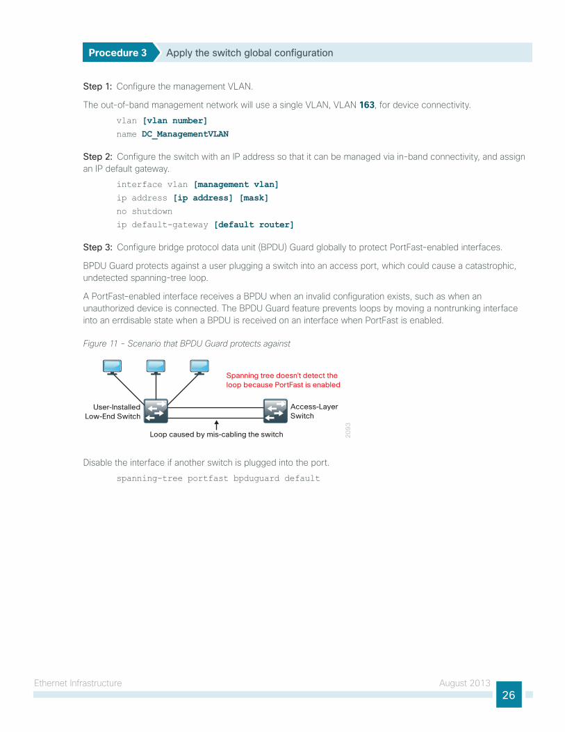
Step 3: Configure bridge protocol data unit (BPDu) guard globally to protect PortFast-enabled interfaces.
BPDu guard protects against a user plugging a switch into an access port, which could cause a catastrophic, undetected spanning-tree loop.
A PortFast-enabled interface receives a BPDu when an invalid configuration exists, such as when an unauthorized device is connected. the BPDu guard feature prevents loops by moving a nontrunking interface into an errdisable state when a BPDu is received on an interface when PortFast is enabled.
Figure 11 - Scenario that BPDU Guard protects against2
09
3
Loop caused by mis-cabling the switch
User-InstalledLow-End Switch
Access-LayerSwitch
Spanning tree doesn’t detect theloop because PortFast is enabled
Disable the interface if another switch is plugged into the port.
spanning-tree portfast bpduguard default
ethernet infrastructure August 201327
Procedure 4 Configure switch access ports
to make configuration easier when the same configuration will be applied to multiple interfaces on the switch, use the interface range command. this command allows you to issue a command once and have it apply to many interfaces at the same time, which can save a lot of time because most of the interfaces in the access layer are configured identically. For example, the following command allows you to enter commands on all 24 interfaces (gig 0/1 to gig 0/24) simultaneously.
interface range Gigabitethernet 1/0/1-24
Step 1: Configure switch interfaces to support management console ports. this host interface configuration supports management port connectivity.
interface range [interface type] [port number]–[port number] switchport access vlan [vlan number] switchport mode access
Step 2: Configure the switch port for host mode. Because only end-device connectivity is provided for the ethernet management ports, shorten the time it takes for the interface to go into a forwarding state by enabling PortFast, disable 802.1Q trunking, and disable channel grouping.
switchport host
Example: Procedures 3 and 4vlan 163 name DC_ManagementVLAN!
interface vlan 163 description in-band management
ip address 10.4.63.5 255.255.255.0 no shutdown
!
ip default-gateway 10.4.63.1!
spanning-tree portfast bpduguard default
!
interface range GigabitEthernet 1/0/1–22 switchport access vlan 163 switchport mode access
switchport host
ethernet infrastructure August 201328
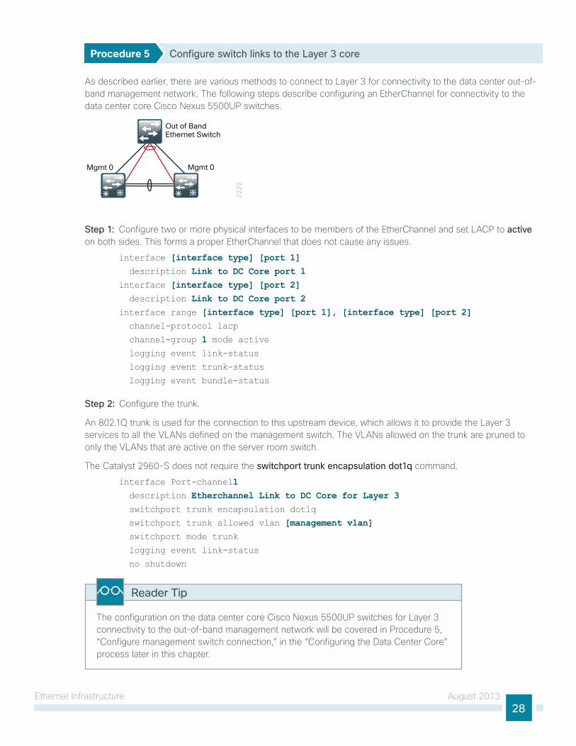
Procedure 5 Configure switch links to the Layer 3 core
As described earlier, there are various methods to connect to layer 3 for connectivity to the data center out-of-band management network. the following steps describe configuring an etherChannel for connectivity to the data center core Cisco nexus 5500uP switches.
22
22
Mgmt 0 Mgmt 0
Out of BandEthernet Switch
Step 1: Configure two or more physical interfaces to be members of the etherChannel and set lACP to active on both sides. this forms a proper etherChannel that does not cause any issues.
interface [interface type] [port 1] description Link to DC Core port 1interface [interface type] [port 2] description Link to DC Core port 2interface range [interface type] [port 1], [interface type] [port 2] channel-protocol lacp
channel-group 1 mode active logging event link-status
logging event trunk-status
logging event bundle-status
Step 2: Configure the trunk.
An 802.1Q trunk is used for the connection to this upstream device, which allows it to provide the layer 3 services to all the VlAns defined on the management switch. the VlAns allowed on the trunk are pruned to only the VlAns that are active on the server room switch.
the Catalyst 2960-s does not require the switchport trunk encapsulation dot1q command.
interface Port-channel1 description Etherchannel Link to DC Core for Layer 3 switchport trunk encapsulation dot1q
switchport trunk allowed vlan [management vlan] switchport mode trunk
logging event link-status
no shutdown
the configuration on the data center core Cisco nexus 5500uP switches for layer 3 connectivity to the out-of-band management network will be covered in Procedure 5, “Configure management switch connection,” in the “Configuring the Data Center Core” process later in this chapter.
Reader Tip
ethernet infrastructure August 201329
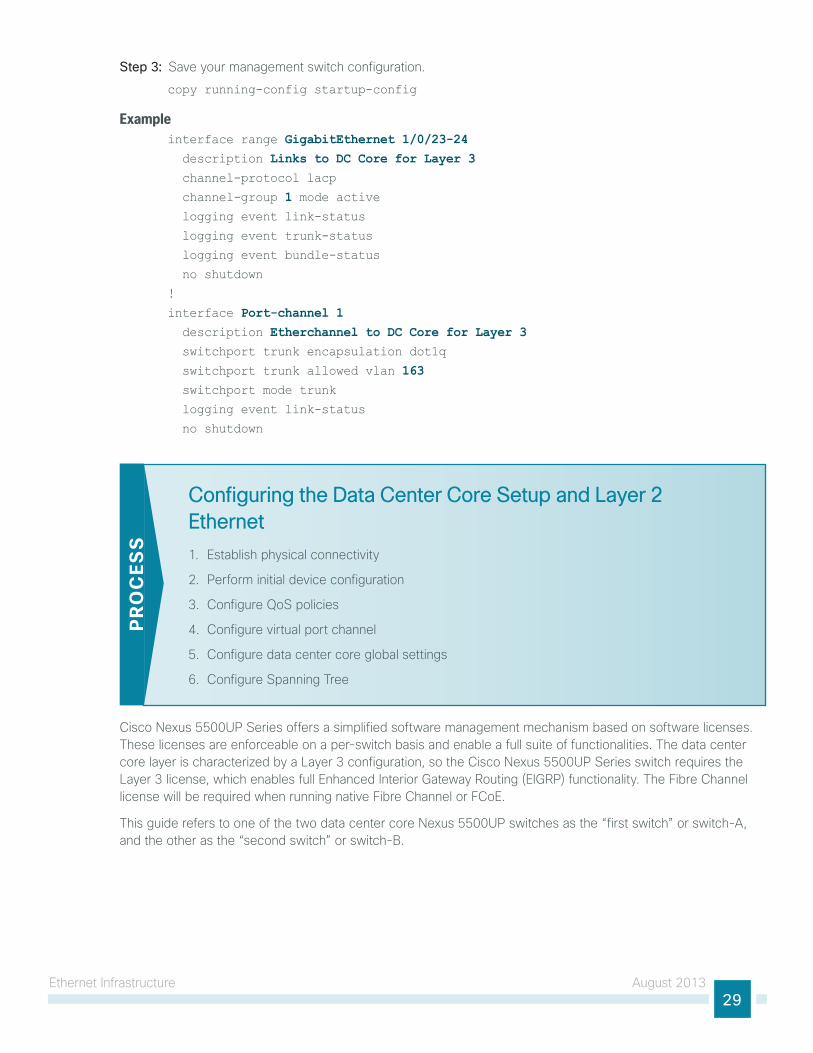
Step 3: save your management switch configuration.
copy running-config startup-config
Exampleinterface range GigabitEthernet 1/0/23-24 description Links to DC Core for Layer 3 channel-protocol lacp
channel-group 1 mode active logging event link-status
logging event trunk-status
logging event bundle-status
no shutdown
!
interface Port-channel 1 description Etherchannel to DC Core for Layer 3 switchport trunk encapsulation dot1q
switchport trunk allowed vlan 163 switchport mode trunk
logging event link-status
no shutdown
Configuring the Data Center Core Setup and Layer 2 Ethernet
1. establish physical connectivity
2. Perform initial device configuration
3. Configure Qos policies
4. Configure virtual port channel
5. Configure data center core global settings
6. Configure spanning tree
PR
OC
ESS
Cisco nexus 5500uP series offers a simplified software management mechanism based on software licenses. these licenses are enforceable on a per-switch basis and enable a full suite of functionalities. the data center core layer is characterized by a layer 3 configuration, so the Cisco nexus 5500uP series switch requires the layer 3 license, which enables full enhanced interior gateway Routing (eigRP) functionality. the Fibre Channel license will be required when running native Fibre Channel or FCoe.
this guide refers to one of the two data center core nexus 5500uP switches as the “first switch” or switch-A, and the other as the “second switch” or switch-B.
ethernet infrastructure August 201330
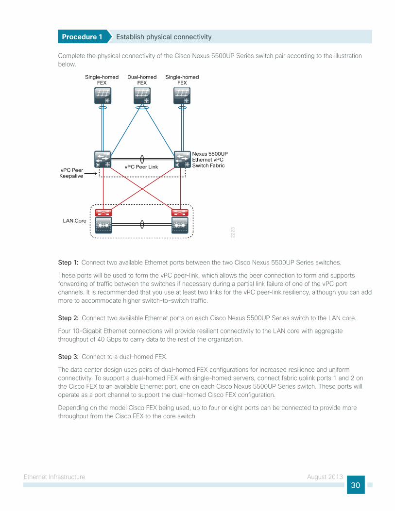
Procedure 1 Establish physical connectivity
Complete the physical connectivity of the Cisco nexus 5500uP series switch pair according to the illustration below.
22
23
vPC PeerKeepalive
LAN Core
vPC Peer Link
Single-homedFEX
Dual-homedFEX
Single-homedFEX
Nexus 5500UPEthernet vPCSwitch Fabric
Step 1: Connect two available ethernet ports between the two Cisco nexus 5500uP series switches.
these ports will be used to form the vPC peer-link, which allows the peer connection to form and supports forwarding of traffic between the switches if necessary during a partial link failure of one of the vPC port channels. it is recommended that you use at least two links for the vPC peer-link resiliency, although you can add more to accommodate higher switch-to-switch traffic.
Step 2: Connect two available ethernet ports on each Cisco nexus 5500uP series switch to the lAn core.
Four 10-gigabit ethernet connections will provide resilient connectivity to the lAn core with aggregate throughput of 40 gbps to carry data to the rest of the organization.
Step 3: Connect to a dual-homed FeX.
the data center design uses pairs of dual-homed FeX configurations for increased resilience and uniform connectivity. to support a dual-homed FeX with single-homed servers, connect fabric uplink ports 1 and 2 on the Cisco FeX to an available ethernet port, one on each Cisco nexus 5500uP series switch. these ports will operate as a port channel to support the dual-homed Cisco FeX configuration.
Depending on the model Cisco FeX being used, up to four or eight ports can be connected to provide more throughput from the Cisco FeX to the core switch.
ethernet infrastructure August 201331
Step 4: Connect to a single-homed FeX.
support single-homed FeX attachment by connecting fabric uplink ports 1 and 2 on each FeX to two available ethernet ports on only one member of the Cisco nexus 5500uP series switch pair. these ports will be a port channel, but will not be configured as a vPC port channel because they have physical ports connected to only one member of the switch pair.
single-homed FeX configurations are beneficial when FCoe connected servers will be connected.
Depending on the model Cisco FeX being used, you can connect up to four or eight ports to provide more throughput from the Cisco FeX to the core switch.
Step 5: Connect to the out-of-band management switch.
this design uses a physically separate, standalone switch for connecting the management ports of the Cisco nexus 5500 switches. the management ports provide out-of-band management access and transport for vPC peer keepalive packets, which are a part of the protection mechanism for vPC operation.
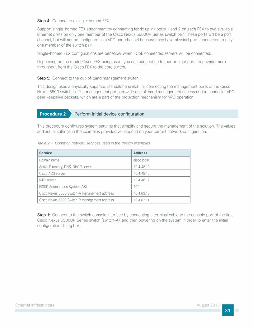
Procedure 2 Perform initial device configuration
this procedure configures system settings that simplify and secure the management of the solution. the values and actual settings in the examples provided will depend on your current network configuration.
Table 2 - Common network services used in the design examples
Service Address
Domain name cisco.local
Active Directory, DNS, DHCP server 10.4.48.10
Cisco ACS server 10.4.48.15
NTP server 10.4.48.17
EIGRP Autonomous System (AS) 100
Cisco Nexus 5500 Switch-A management address 10.4.63.10
Cisco Nexus 5500 Switch-B management address 10.4.63.11
Step 1: Connect to the switch console interface by connecting a terminal cable to the console port of the first Cisco nexus 5500uP series switch (switch-A), and then powering on the system in order to enter the initial configuration dialog box.
ethernet infrastructure August 201332
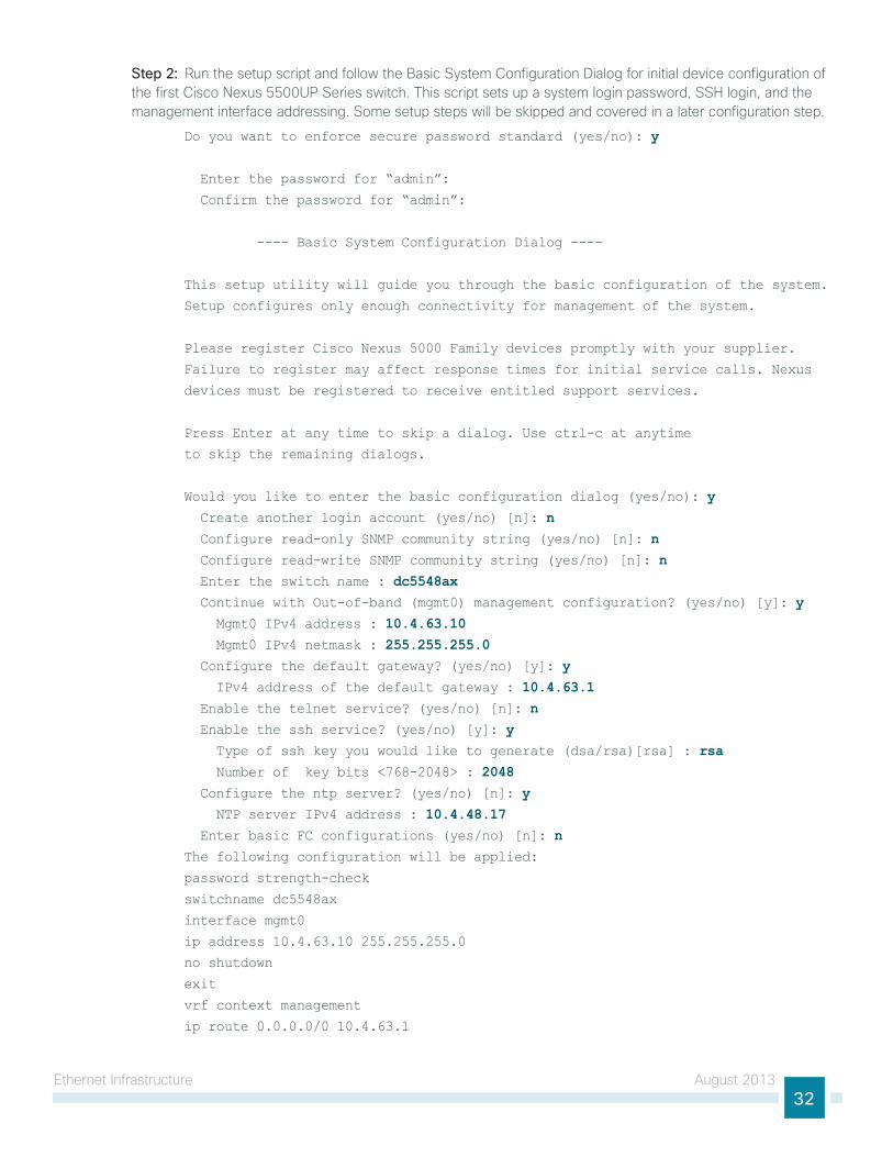
Step 2: Run the setup script and follow the Basic system Configuration Dialog for initial device configuration of the first Cisco nexus 5500uP series switch. this script sets up a system login password, ssh login, and the management interface addressing. some setup steps will be skipped and covered in a later configuration step.
Do you want to enforce secure password standard (yes/no): y
Enter the password for “admin”:
Confirm the password for “admin”:
---- Basic System Configuration Dialog ----
This setup utility will guide you through the basic configuration of the system.
Setup configures only enough connectivity for management of the system.
Please register Cisco Nexus 5000 Family devices promptly with your supplier.
Failure to register may affect response times for initial service calls. Nexus
devices must be registered to receive entitled support services.
Press Enter at any time to skip a dialog. Use ctrl-c at anytime
to skip the remaining dialogs.
Would you like to enter the basic configuration dialog (yes/no): y Create another login account (yes/no) [n]: n Configure read-only SNMP community string (yes/no) [n]: n Configure read-write SNMP community string (yes/no) [n]: n Enter the switch name : dc5548ax Continue with Out-of-band (mgmt0) management configuration? (yes/no) [y]: y Mgmt0 IPv4 address : 10.4.63.10 Mgmt0 IPv4 netmask : 255.255.255.0 Configure the default gateway? (yes/no) [y]: y IPv4 address of the default gateway : 10.4.63.1 Enable the telnet service? (yes/no) [n]: n Enable the ssh service? (yes/no) [y]: y Type of ssh key you would like to generate (dsa/rsa)[rsa] : rsa Number of key bits <768-2048> : 2048 Configure the ntp server? (yes/no) [n]: y NTP server IPv4 address : 10.4.48.17 Enter basic FC configurations (yes/no) [n]: nThe following configuration will be applied:
password strength-check
switchname dc5548ax
interface mgmt0
ip address 10.4.63.10 255.255.255.0
no shutdown
exit
vrf context management
ip route 0.0.0.0/0 10.4.63.1
ethernet infrastructure August 201333
exit
no telnet server enable
ssh server enable
ssh key rsa 2048 force
ntp server 10.4.48.17 use-vrf management
Would you like to edit the configuration? (yes/no) [n]: nUse this configuration and save it? (yes/no) [y]: y[########################################] 100%
dc5548ax login:
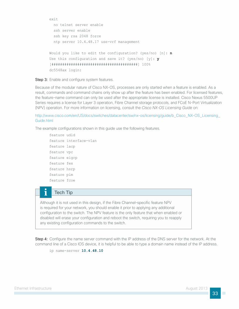
Step 3: enable and configure system features.
Because of the modular nature of Cisco nX-os, processes are only started when a feature is enabled. As a result, commands and command chains only show up after the feature has been enabled. For licensed features, the feature-name command can only be used after the appropriate license is installed. Cisco nexus 5500uP series requires a license for layer 3 operation, Fibre Channel storage protocols, and FCoe n-Port Virtualization (nPV) operation. For more information on licensing, consult the Cisco NX-OS Licensing Guide on:
http://www.cisco.com/en/us/docs/switches/datacenter/sw/nx-os/licensing/guide/b_Cisco_nX-os_licensing_guide.html
the example configurations shown in this guide use the following features.
feature udld
feature interface-vlan
feature lacp
feature vpc
feature eigrp
feature fex
feature hsrp
feature pim
feature fcoe
Although it is not used in this design, if the Fibre Channel–specific feature nPV is required for your network, you should enable it prior to applying any additional configuration to the switch. the nPV feature is the only feature that when enabled or disabled will erase your configuration and reboot the switch, requiring you to reapply any existing configuration commands to the switch.
Tech Tip
Step 4: Configure the name server command with the iP address of the Dns server for the network. At the command line of a Cisco ios device, it is helpful to be able to type a domain name instead of the iP address.
ip name-server 10.4.48.10
ethernet infrastructure August 201334
Step 5: set local time zone for the device location. ntP is designed to synchronize time across all devices in a network for troubleshooting. in the initial setup script, you set the ntP server address. now set the local time for the device location.
clock timezone PST -8 0clock summer-time PDT 2 Sunday march 02:00 1 Sunday nov 02:00 60
Step 6: Define a read-only and a read/write snMP community for network management.
snmp-server community cisco group network-operatorsnmp-server community cisco123 group network-admin
Step 7: if you want to reduce operational tasks per device, configure centralized user authentication by using the tACACs+ protocol to authenticate management logins on the infrastructure devices to the AAA server.
As networks scale in the number of devices to maintain, the operational burden to maintain local user accounts on every device also scales. A centralized AAA service reduces operational tasks per device and provides an audit log of user access for security compliance and root-cause analysis. When AAA is enabled for access control, all management access to the network infrastructure devices (ssh and httPs) is controlled by AAA.
tACACs+ is the primary protocol used to authenticate management logins on the infrastructure devices to the AAA server. A local AAA user database is also defined in the setup script on each Cisco nexus 5500 switch to provide a fallback authentication source in case the centralized tACACs+ server is unavailable.
feature tacacs+
tacacs-server host 10.4.48.15 key SecretKeyaaa group server tacacs+ tacacs server 10.4.48.15 use-vrf default
aaa authentication login default group tacacs
Step 8: if operational support is centralized in your network, you can increase network security by using an access list to limit the networks that can access your device. in this example, only devices on the 10.4.48.0/24 network will be able to access the device via ssh or snMP.
ip access-list vty-acl-in permit tcp 10.4.48.0/24 any eq 22
line vty
ip access-class vty-acl-in in
!
ip access-list snmp-acl
permit udp 10.4.48.0/24 any eq snmp
snmp-server community cisco use-acl snmp-aclsnmp-server community cisco123 use-acl snmp-acl
if you configure an access list on the vty interface, you may lose the ability to use ssh to log in from one router to the next for hop-by-hop troubleshooting.
Caution
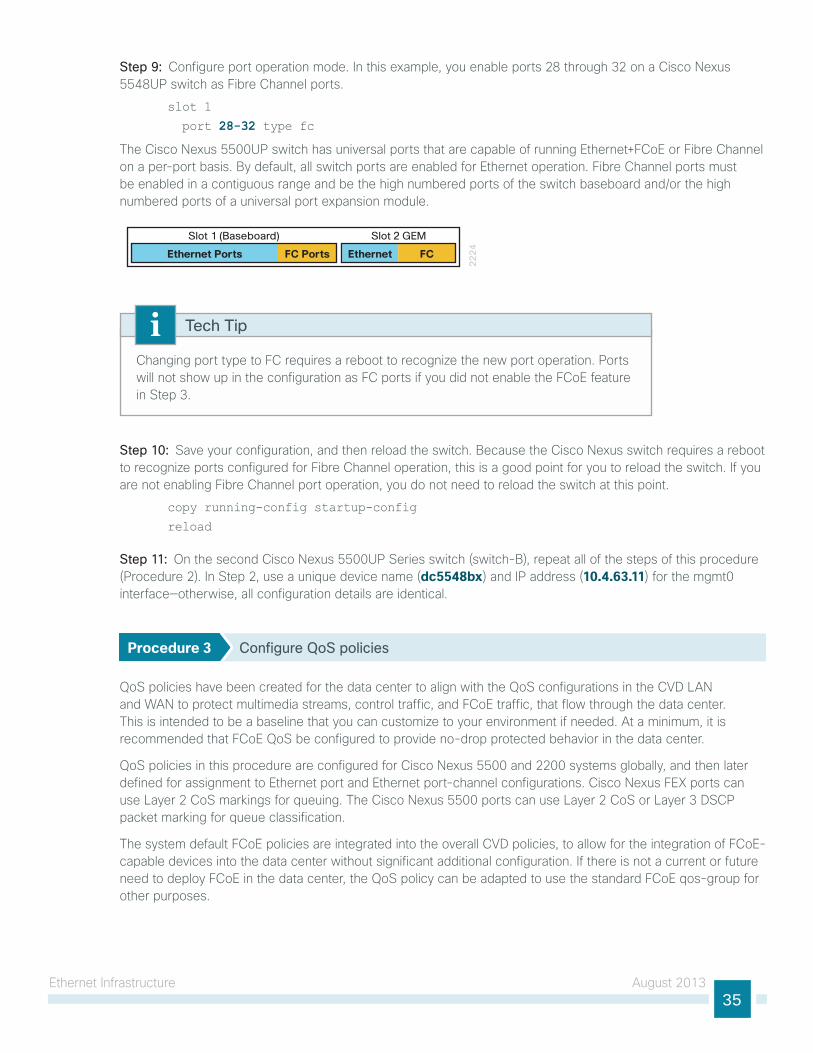
ethernet infrastructure August 201335
Step 9: Configure port operation mode. in this example, you enable ports 28 through 32 on a Cisco nexus 5548uP switch as Fibre Channel ports.
slot 1
port 28-32 type fc
the Cisco nexus 5500uP switch has universal ports that are capable of running ethernet+FCoe or Fibre Channel on a per-port basis. By default, all switch ports are enabled for ethernet operation. Fibre Channel ports must be enabled in a contiguous range and be the high numbered ports of the switch baseboard and/or the high numbered ports of a universal port expansion module.
22
24
Slot 1 (Baseboard) Slot 2 GEM
Ethernet Ports FC Ports Ethernet FC
Changing port type to FC requires a reboot to recognize the new port operation. Ports will not show up in the configuration as FC ports if you did not enable the FCoe feature in step 3.
Tech Tip
Step 10: save your configuration, and then reload the switch. Because the Cisco nexus switch requires a reboot to recognize ports configured for Fibre Channel operation, this is a good point for you to reload the switch. if you are not enabling Fibre Channel port operation, you do not need to reload the switch at this point.
copy running-config startup-config
reload
Step 11: on the second Cisco nexus 5500uP series switch (switch-B), repeat all of the steps of this procedure (Procedure 2). in step 2, use a unique device name (dc5548bx) and iP address (10.4.63.11) for the mgmt0 interface—otherwise, all configuration details are identical.
Procedure 3 Configure QoS policies
Qos policies have been created for the data center to align with the Qos configurations in the CVD lAn and WAn to protect multimedia streams, control traffic, and FCoe traffic, that flow through the data center. this is intended to be a baseline that you can customize to your environment if needed. At a minimum, it is recommended that FCoe Qos be configured to provide no-drop protected behavior in the data center.
Qos policies in this procedure are configured for Cisco nexus 5500 and 2200 systems globally, and then later defined for assignment to ethernet port and ethernet port-channel configurations. Cisco nexus FeX ports can use layer 2 Cos markings for queuing. the Cisco nexus 5500 ports can use layer 2 Cos or layer 3 DsCP packet marking for queue classification.
the system default FCoe policies are integrated into the overall CVD policies, to allow for the integration of FCoe-capable devices into the data center without significant additional configuration. if there is not a current or future need to deploy FCoe in the data center, the Qos policy can be adapted to use the standard FCoe qos-group for other purposes.
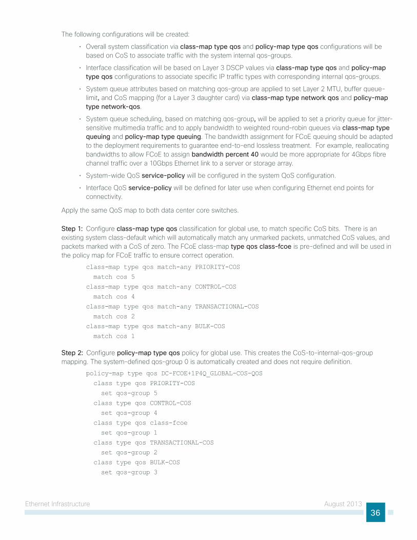
ethernet infrastructure August 201336
the following configurations will be created:
• overall system classification via class-map type qos and policy-map type qos configurations will be based on Cos to associate traffic with the system internal qos-groups.
• interface classification will be based on layer 3 DsCP values via class-map type qos and policy-map type qos configurations to associate specific iP traffic types with corresponding internal qos-groups.
• system queue attributes based on matching qos-group are applied to set layer 2 Mtu, buffer queue-limit, and Cos mapping (for a layer 3 daughter card) via class-map type network qos and policy-map type network-qos.
• system queue scheduling, based on matching qos-group, will be applied to set a priority queue for jitter-sensitive multimedia traffic and to apply bandwidth to weighted round-robin queues via class-map type queuing and policy-map type queuing. the bandwidth assignment for FCoe queuing should be adapted to the deployment requirements to guarantee end-to-end lossless treatment. For example, reallocating bandwidths to allow FCoe to assign bandwidth percent 40 would be more appropriate for 4gbps fibre channel traffic over a 10gbps ethernet link to a server or storage array.
• system-wide Qos service-policy will be configured in the system Qos configuration.
• interface Qos service-policy will be defined for later use when configuring ethernet end points for connectivity.
Apply the same Qos map to both data center core switches.
Step 1: Configure class-map type qos classification for global use, to match specific Cos bits. there is an existing system class-default which will automatically match any unmarked packets, unmatched Cos values, and packets marked with a Cos of zero. the FCoe class-map type qos class-fcoe is pre-defined and will be used in the policy map for FCoe traffic to ensure correct operation.
class-map type qos match-any PRIORITY-COS
match cos 5
class-map type qos match-any CONTROL-COS
match cos 4
class-map type qos match-any TRANSACTIONAL-COS
match cos 2
class-map type qos match-any BULK-COS
match cos 1
Step 2: Configure policy-map type qos policy for global use. this creates the Cos-to-internal-qos-group mapping. the system-defined qos-group 0 is automatically created and does not require definition.
policy-map type qos DC-FCOE+1P4Q_GLOBAL-COS-QOS
class type qos PRIORITY-COS
set qos-group 5
class type qos CONTROL-COS
set qos-group 4
class type qos class-fcoe
set qos-group 1
class type qos TRANSACTIONAL-COS
set qos-group 2
class type qos BULK-COS
set qos-group 3
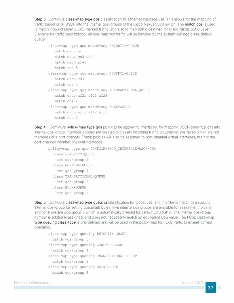
ethernet infrastructure August 201337
Step 3: Configure class-map type qos classification for ethernet interface use. this allows for the mapping of traffic based on iP DsCP into the internal qos-groups of the Cisco nexus 5500 switch. the match cos is used to match inbound layer 2 Cos marked traffic, and also to map traffic destined for Cisco nexus 5500 layer 3 engine for traffic prioritization. All non-matched traffic will be handled by the system-defined class-default queue.
class-map type qos match-any PRIORITY-QUEUE
match dscp ef
match dscp cs5 cs4
match dscp af41
match cos 5
class-map type qos match-any CONTROL-QUEUE
match dscp cs3
match cos 4
class-map type qos match-any TRANSACTIONAL-QUEUE
match dscp af21 af22 af23
match cos 2
class-map type qos match-any BULK-QUEUE
match dscp af11 af12 af13
match cos 1
Step 4: Configure policy-map type qos policy to be applied to interfaces, for mapping DsCP classifications into internal qos-group. interface policies are created to classify incoming traffic on ethernet interfaces which are not members of a port-channel. these policies will also be assigned to port-channel virtual interfaces, but not the port-channel member physical interfaces.
policy-map type qos DC-FCOE+1P4Q_INTERFACE-DSCP-QOS
class PRIORITY-QUEUE
set qos-group 5
class CONTROL-QUEUE
set qos-group 4
class TRANSACTIONAL-QUEUE
set qos-group 2
class BULK-QUEUE
set qos-group 3
Step 5: Configure class-map type queuing classification for global use, and in order to match to a specific internal qos-group for setting queue attributes. Five internal qos groups are available for assignment, plus an additional system qos-group 0 which is automatically created for default Cos traffic. the internal qos-group number is arbitrarily assigned, and does not necessarily match an equivalent Cos value. the FCoe class-map type queuing class-fcoe is pre-defined and will be used in the policy map for FCoe traffic to ensure correct operation.
class-map type queuing PRIORITY-GROUP
match qos-group 5
class-map type queuing CONTROL-GROUP
match qos-group 4
class-map type queuing TRANSACTIONAL-GROUP
match qos-group 2
class-map type queuing BULK-GROUP
match qos-group 3
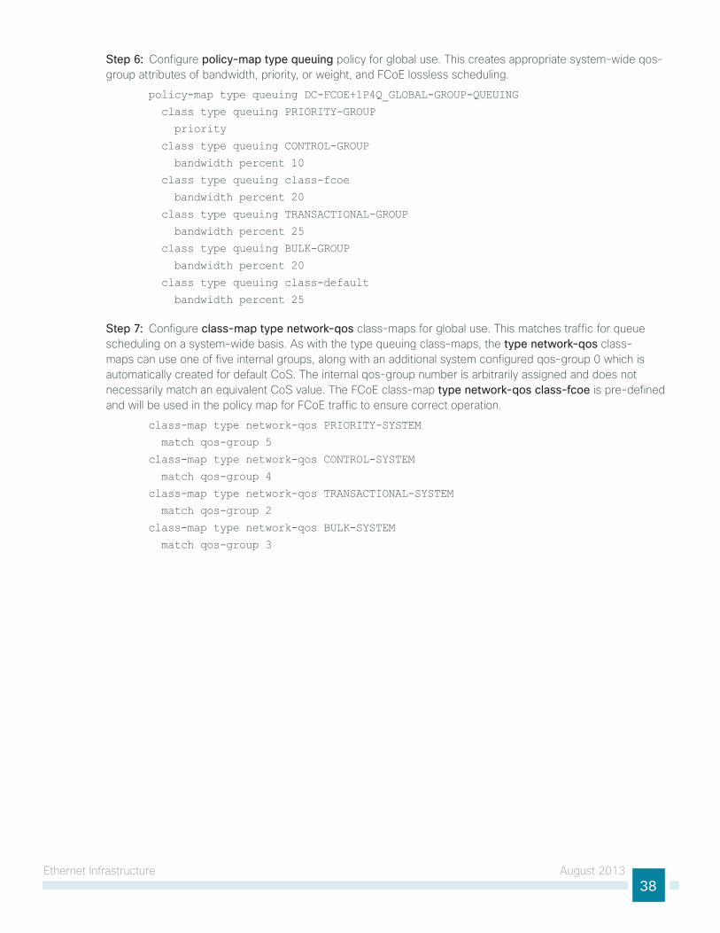
ethernet infrastructure August 201338
Step 6: Configure policy-map type queuing policy for global use. this creates appropriate system-wide qos-group attributes of bandwidth, priority, or weight, and FCoe lossless scheduling.
policy-map type queuing DC-FCOE+1P4Q_GLOBAL-GROUP-QUEUING
class type queuing PRIORITY-GROUP
priority
class type queuing CONTROL-GROUP
bandwidth percent 10
class type queuing class-fcoe
bandwidth percent 20
class type queuing TRANSACTIONAL-GROUP
bandwidth percent 25
class type queuing BULK-GROUP
bandwidth percent 20
class type queuing class-default
bandwidth percent 25
Step 7: Configure class-map type network-qos class-maps for global use. this matches traffic for queue scheduling on a system-wide basis. As with the type queuing class-maps, the type network-qos class-maps can use one of five internal groups, along with an additional system configured qos-group 0 which is automatically created for default Cos. the internal qos-group number is arbitrarily assigned and does not necessarily match an equivalent Cos value. the FCoe class-map type network-qos class-fcoe is pre-defined and will be used in the policy map for FCoe traffic to ensure correct operation.
class-map type network-qos PRIORITY-SYSTEM
match qos-group 5
class-map type network-qos CONTROL-SYSTEM
match qos-group 4
class-map type network-qos TRANSACTIONAL-SYSTEM
match qos-group 2
class-map type network-qos BULK-SYSTEM
match qos-group 3
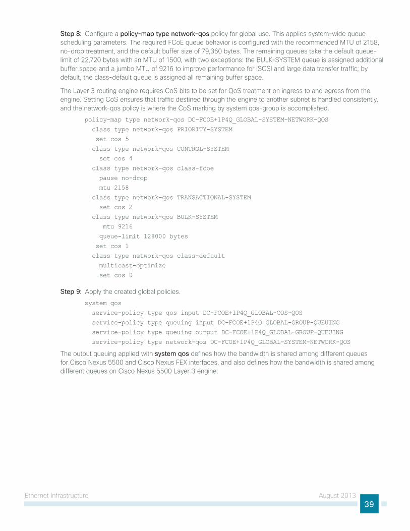
ethernet infrastructure August 201339
Step 8: Configure a policy-map type network-qos policy for global use. this applies system-wide queue scheduling parameters. the required FCoe queue behavior is configured with the recommended Mtu of 2158, no-drop treatment, and the default buffer size of 79,360 bytes. the remaining queues take the default queue-limit of 22,720 bytes with an Mtu of 1500, with two exceptions: the BulK-systeM queue is assigned additional buffer space and a jumbo Mtu of 9216 to improve performance for isCsi and large data transfer traffic; by default, the class-default queue is assigned all remaining buffer space.
the layer 3 routing engine requires Cos bits to be set for Qos treatment on ingress to and egress from the engine. setting Cos ensures that traffic destined through the engine to another subnet is handled consistently, and the network-qos policy is where the Cos marking by system qos-group is accomplished.
policy-map type network-qos DC-FCOE+1P4Q_GLOBAL-SYSTEM-NETWORK-QOS
class type network-qos PRIORITY-SYSTEM
set cos 5
class type network-qos CONTROL-SYSTEM
set cos 4
class type network-qos class-fcoe
pause no-drop
mtu 2158
class type network-qos TRANSACTIONAL-SYSTEM
set cos 2
class type network-qos BULK-SYSTEM
mtu 9216
queue-limit 128000 bytes
set cos 1
class type network-qos class-default
multicast-optimize
set cos 0
Step 9: Apply the created global policies.
system qos
service-policy type qos input DC-FCOE+1P4Q_GLOBAL-COS-QOS
service-policy type queuing input DC-FCOE+1P4Q_GLOBAL-GROUP-QUEUING
service-policy type queuing output DC-FCOE+1P4Q_GLOBAL-GROUP-QUEUING
service-policy type network-qos DC-FCOE+1P4Q_GLOBAL-SYSTEM-NETWORK-QOS
the output queuing applied with system qos defines how the bandwidth is shared among different queues for Cisco nexus 5500 and Cisco nexus FeX interfaces, and also defines how the bandwidth is shared among different queues on Cisco nexus 5500 layer 3 engine.
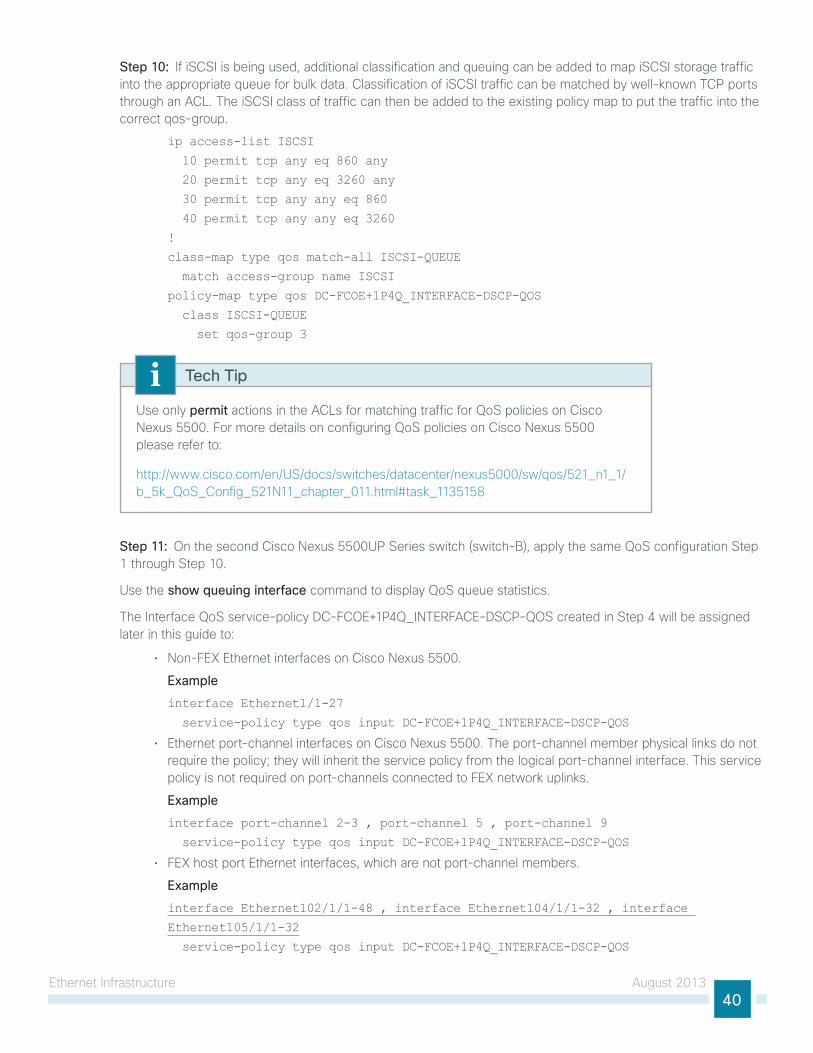
ethernet infrastructure August 201340
Step 10: if isCsi is being used, additional classification and queuing can be added to map isCsi storage traffic into the appropriate queue for bulk data. Classification of isCsi traffic can be matched by well-known tCP ports through an ACl. the isCsi class of traffic can then be added to the existing policy map to put the traffic into the correct qos-group.
ip access-list ISCSI
10 permit tcp any eq 860 any
20 permit tcp any eq 3260 any
30 permit tcp any any eq 860
40 permit tcp any any eq 3260
!
class-map type qos match-all ISCSI-QUEUE
match access-group name ISCSI
policy-map type qos DC-FCOE+1P4Q_INTERFACE-DSCP-QOS
class ISCSI-QUEUE
set qos-group 3
use only permit actions in the ACls for matching traffic for Qos policies on Cisco nexus 5500. For more details on configuring Qos policies on Cisco nexus 5500 please refer to:
http://www.cisco.com/en/us/docs/switches/datacenter/nexus5000/sw/qos/521_n1_1/b_5k_Qos_Config_521n11_chapter_011.html#task_1135158
Tech Tip
Step 11: on the second Cisco nexus 5500uP series switch (switch-B), apply the same Qos configuration step 1 through step 10.
use the show queuing interface command to display Qos queue statistics.
the interface Qos service-policy DC-FCoe+1P4Q_inteRFACe-DsCP-Qos created in step 4 will be assigned later in this guide to:
• non-FeX ethernet interfaces on Cisco nexus 5500.
Example
interface Ethernet1/1-27
service-policy type qos input DC-FCOE+1P4Q_INTERFACE-DSCP-QOS
• ethernet port-channel interfaces on Cisco nexus 5500. the port-channel member physical links do not require the policy; they will inherit the service policy from the logical port-channel interface. this service policy is not required on port-channels connected to FeX network uplinks.
Example
interface port-channel 2-3 , port-channel 5 , port-channel 9
service-policy type qos input DC-FCOE+1P4Q_INTERFACE-DSCP-QOS
• FeX host port ethernet interfaces, which are not port-channel members.
Example
interface Ethernet102/1/1-48 , interface Ethernet104/1/1-32 , interface
Ethernet105/1/1-32
service-policy type qos input DC-FCOE+1P4Q_INTERFACE-DSCP-QOS
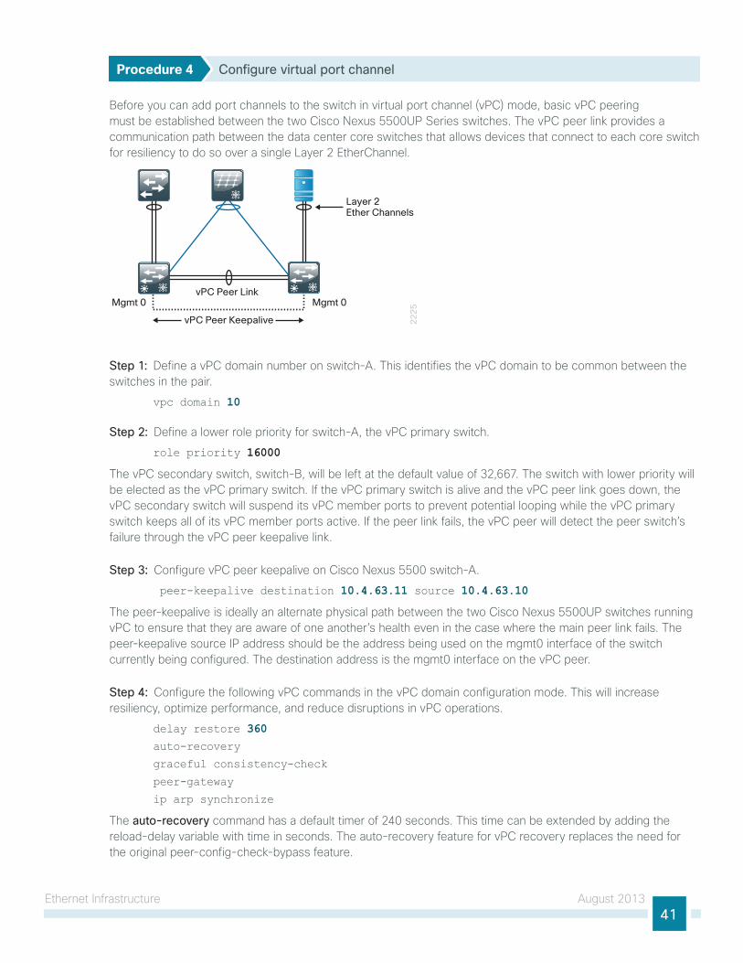
ethernet infrastructure August 201341
Procedure 4 Configure virtual port channel
Before you can add port channels to the switch in virtual port channel (vPC) mode, basic vPC peering must be established between the two Cisco nexus 5500uP series switches. the vPC peer link provides a communication path between the data center core switches that allows devices that connect to each core switch for resiliency to do so over a single layer 2 etherChannel.
22
25
vPC Peer LinkMgmt 0 Mgmt 0
vPC Peer Keepalive
Layer 2Ether Channels
Step 1: Define a vPC domain number on switch-A. this identifies the vPC domain to be common between the switches in the pair.
vpc domain 10
Step 2: Define a lower role priority for switch-A, the vPC primary switch.
role priority 16000
the vPC secondary switch, switch-B, will be left at the default value of 32,667. the switch with lower priority will be elected as the vPC primary switch. if the vPC primary switch is alive and the vPC peer link goes down, the vPC secondary switch will suspend its vPC member ports to prevent potential looping while the vPC primary switch keeps all of its vPC member ports active. if the peer link fails, the vPC peer will detect the peer switch’s failure through the vPC peer keepalive link.
Step 3: Configure vPC peer keepalive on Cisco nexus 5500 switch-A.
peer-keepalive destination 10.4.63.11 source 10.4.63.10
the peer-keepalive is ideally an alternate physical path between the two Cisco nexus 5500uP switches running vPC to ensure that they are aware of one another’s health even in the case where the main peer link fails. the peer-keepalive source iP address should be the address being used on the mgmt0 interface of the switch currently being configured. the destination address is the mgmt0 interface on the vPC peer.
Step 4: Configure the following vPC commands in the vPC domain configuration mode. this will increase resiliency, optimize performance, and reduce disruptions in vPC operations.
delay restore 360auto-recovery
graceful consistency-check
peer-gateway
ip arp synchronize
the auto-recovery command has a default timer of 240 seconds. this time can be extended by adding the reload-delay variable with time in seconds. the auto-recovery feature for vPC recovery replaces the need for the original peer-config-check-bypass feature.
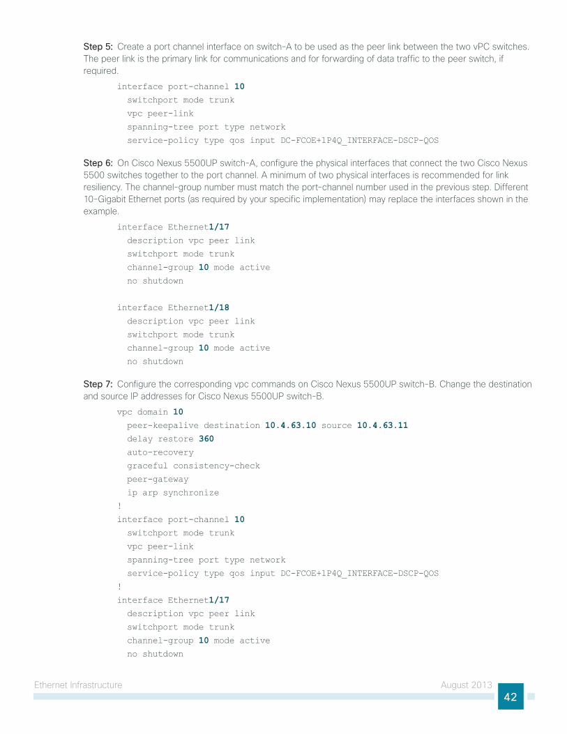
ethernet infrastructure August 201342
Step 5: Create a port channel interface on switch-A to be used as the peer link between the two vPC switches. the peer link is the primary link for communications and for forwarding of data traffic to the peer switch, if required.
interface port-channel 10 switchport mode trunk
vpc peer-link
spanning-tree port type network
service-policy type qos input DC-FCOE+1P4Q_INTERFACE-DSCP-QOS
Step 6: on Cisco nexus 5500uP switch-A, configure the physical interfaces that connect the two Cisco nexus 5500 switches together to the port channel. A minimum of two physical interfaces is recommended for link resiliency. the channel-group number must match the port-channel number used in the previous step. Different 10-gigabit ethernet ports (as required by your specific implementation) may replace the interfaces shown in the example.
interface Ethernet1/17 description vpc peer link
switchport mode trunk
channel-group 10 mode active no shutdown
interface Ethernet1/18 description vpc peer link
switchport mode trunk
channel-group 10 mode active no shutdown
Step 7: Configure the corresponding vpc commands on Cisco nexus 5500uP switch-B. Change the destination and source iP addresses for Cisco nexus 5500uP switch-B.
vpc domain 10 peer-keepalive destination 10.4.63.10 source 10.4.63.11 delay restore 360 auto-recovery
graceful consistency-check
peer-gateway
ip arp synchronize
!
interface port-channel 10 switchport mode trunk
vpc peer-link
spanning-tree port type network
service-policy type qos input DC-FCOE+1P4Q_INTERFACE-DSCP-QOS
!
interface Ethernet1/17 description vpc peer link
switchport mode trunk
channel-group 10 mode active no shutdown
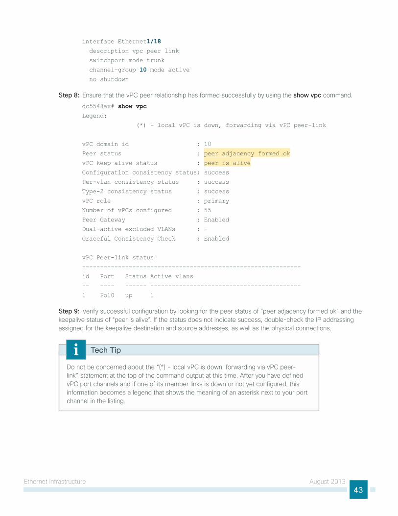
ethernet infrastructure August 201343
interface Ethernet1/18 description vpc peer link
switchport mode trunk
channel-group 10 mode active no shutdown
Step 8: ensure that the vPC peer relationship has formed successfully by using the show vpc command.
dc5548ax# show vpcLegend:
(*) - local vPC is down, forwarding via vPC peer-link
vPC domain id : 10
Peer status : peer adjacency formed ok
vPC keep-alive status : peer is alive
Configuration consistency status: success
Per-vlan consistency status : success
Type-2 consistency status : success
vPC role : primary
Number of vPCs configured : 55
Peer Gateway : Enabled
Dual-active excluded VLANs : -
Graceful Consistency Check : Enabled
vPC Peer-link status
-------------------------------------------------------------
id Port Status Active vlans
-- ---- ------ ------------------------------------------
1 Po10 up 1
Step 9: Verify successful configuration by looking for the peer status of “peer adjacency formed ok” and the keepalive status of “peer is alive”. if the status does not indicate success, double-check the iP addressing assigned for the keepalive destination and source addresses, as well as the physical connections.
Do not be concerned about the “(*) - local vPC is down, forwarding via vPC peer-link” statement at the top of the command output at this time. After you have defined vPC port channels and if one of its member links is down or not yet configured, this information becomes a legend that shows the meaning of an asterisk next to your port channel in the listing.
Tech Tip
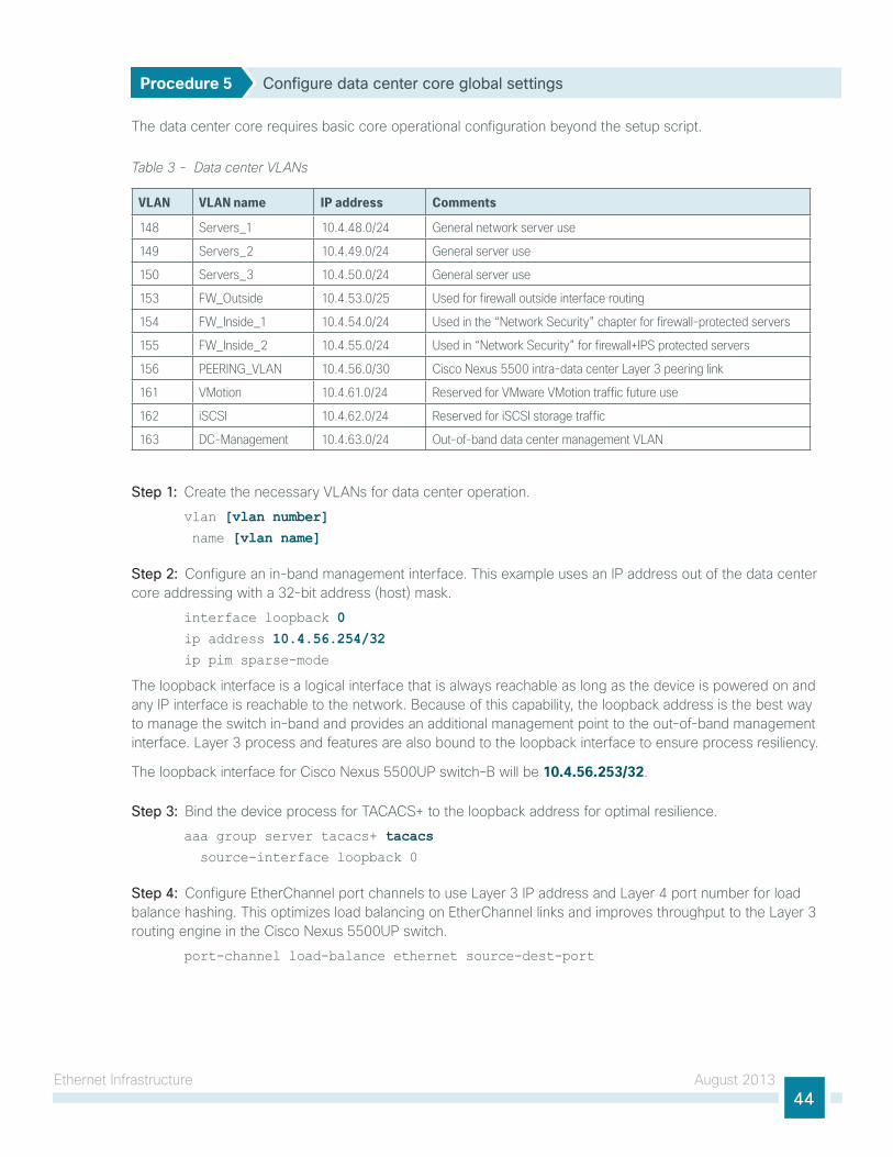
ethernet infrastructure August 201344
Procedure 5 Configure data center core global settings
the data center core requires basic core operational configuration beyond the setup script.
Table 3 - Data center VLANs
VLAN VLAN name IP address Comments
148 Servers_1 10.4.48.0/24 General network server use
149 Servers_2 10.4.49.0/24 General server use
150 Servers_3 10.4.50.0/24 General server use
153 FW_Outside 10.4.53.0/25 Used for firewall outside interface routing
154 FW_Inside_1 10.4.54.0/24 Used in the “Network Security” chapter for firewall-protected servers
155 FW_Inside_2 10.4.55.0/24 Used in “Network Security” for firewall+IPS protected servers
156 PEERING_VLAN 10.4.56.0/30 Cisco Nexus 5500 intra-data center Layer 3 peering link
161 VMotion 10.4.61.0/24 Reserved for VMware VMotion traffic future use
162 iSCSI 10.4.62.0/24 Reserved for iSCSI storage traffic
163 DC-Management 10.4.63.0/24 Out-of-band data center management VLAN
Step 1: Create the necessary VlAns for data center operation.
vlan [vlan number] name [vlan name]
Step 2: Configure an in-band management interface. this example uses an iP address out of the data center core addressing with a 32-bit address (host) mask.
interface loopback 0ip address 10.4.56.254/32ip pim sparse-mode
the loopback interface is a logical interface that is always reachable as long as the device is powered on and any iP interface is reachable to the network. Because of this capability, the loopback address is the best way to manage the switch in-band and provides an additional management point to the out-of-band management interface. layer 3 process and features are also bound to the loopback interface to ensure process resiliency.
the loopback interface for Cisco nexus 5500uP switch-B will be 10.4.56.253/32.
Step 3: Bind the device process for tACACs+ to the loopback address for optimal resilience.
aaa group server tacacs+ tacacs source-interface loopback 0
Step 4: Configure etherChannel port channels to use layer 3 iP address and layer 4 port number for load balance hashing. this optimizes load balancing on etherChannel links and improves throughput to the layer 3 routing engine in the Cisco nexus 5500uP switch.
port-channel load-balance ethernet source-dest-port
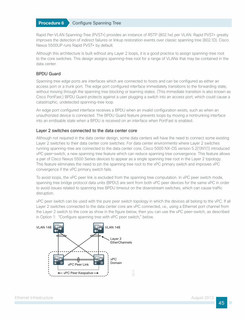
ethernet infrastructure August 201345
Procedure 6 Configure Spanning Tree
Rapid Per-VlAn spanning-tree (PVst+) provides an instance of RstP (802.1w) per VlAn. Rapid PVst+ greatly improves the detection of indirect failures or linkup restoration events over classic spanning tree (802.1D). Cisco nexus 5500uP runs Rapid PVst+ by default.
Although this architecture is built without any layer 2 loops, it is a good practice to assign spanning-tree root to the core switches. this design assigns spanning-tree root for a range of VlAns that may be contained in the data center.
BPDU Guard
spanning tree edge ports are interfaces which are connected to hosts and can be configured as either an access port or a trunk port. the edge port configured interface immediately transitions to the forwarding state, without moving through the spanning tree blocking or learning states. (this immediate transition is also known as Cisco PortFast.) BPDu guard protects against a user plugging a switch into an access port, which could cause a catastrophic, undetected spanning-tree loop.
An edge port configured interface receives a BPDu when an invalid configuration exists, such as when an unauthorized device is connected. the BPDu guard feature prevents loops by moving a nontrunking interface into an errdisable state when a BPDu is received on an interface when PortFast is enabled.
Layer 2 switches connected to the data center core
Although not required in the data center design, some data centers will have the need to connect some existing layer 2 switches to their data center core switches. For data center environments where layer 2 switches running spanning-tree are connected to the data center core, Cisco 5000 nX-os version 5.2(1)n1(1) introduced vPC peer-switch, a new spanning tree feature which can reduce spanning tree convergence. this feature allows a pair of Cisco nexus 5500 series devices to appear as a single spanning tree root in the layer 2 topology. this feature eliminates the need to pin the spanning tree root to the vPC primary switch and improves vPC convergence if the vPC primary switch fails.
to avoid loops, the vPC peer link is excluded from the spanning tree computation. in vPC peer switch mode, spanning tree bridge protocol data units (BPDu) are sent from both vPC peer devices for the same vPC in order to avoid issues related to spanning tree BPDu timeout on the downstream switches, which can cause traffic disruption.
vPC peer switch can be used with the pure peer switch topology in which the devices all belong to the vPC. if all layer 2 switches connected to the data center core are vPC connected, i.e., using a ethernet port channel from the layer 2 switch to the core as show in the figure below, then you can use the vPC peer-switch, as described in option 1: “Configure spanning tree with vPC peer switch,” below.
22
17
Layer 2EtherChannels
vPC Peer Keepalive
vPC Peer Link
VLAN 148 VLAN 148
vPCDomain
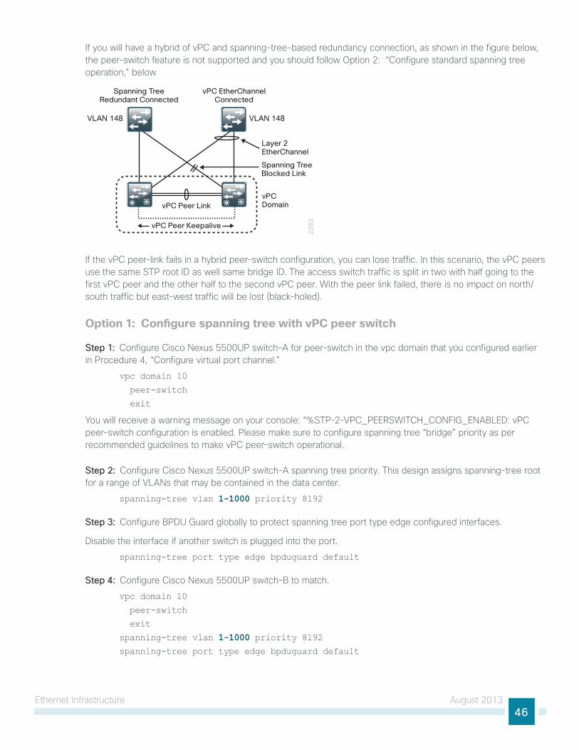
ethernet infrastructure August 201346
if you will have a hybrid of vPC and spanning-tree-based redundancy connection, as shown in the figure below, the peer-switch feature is not supported and you should follow option 2: “Configure standard spanning tree operation,” below
22
83
Spanning TreeRedundant Connected
vPC EtherChannelConnected
Spanning TreeBlocked Link
Layer 2EtherChannel
vPC Peer Keepalive
vPC Peer Link
VLAN 148 VLAN 148
vPCDomain
if the vPC peer-link fails in a hybrid peer-switch configuration, you can lose traffic. in this scenario, the vPC peers use the same stP root iD as well same bridge iD. the access switch traffic is split in two with half going to the first vPC peer and the other half to the second vPC peer. With the peer link failed, there is no impact on north/south traffic but east-west traffic will be lost (black-holed).
Option 1: Configure spanning tree with vPC peer switch
Step 1: Configure Cisco nexus 5500uP switch-A for peer-switch in the vpc domain that you configured earlier in Procedure 4, “Configure virtual port channel.”
vpc domain 10
peer-switch
exit
you will receive a warning message on your console: “%stP-2-VPC_PeeRsWitCh_ConFig_enABleD: vPC peer-switch configuration is enabled. Please make sure to configure spanning tree “bridge” priority as per recommended guidelines to make vPC peer-switch operational.
Step 2: Configure Cisco nexus 5500uP switch-A spanning tree priority. this design assigns spanning-tree root for a range of VlAns that may be contained in the data center.
spanning-tree vlan 1-1000 priority 8192
Step 3: Configure BPDu guard globally to protect spanning tree port type edge configured interfaces.
Disable the interface if another switch is plugged into the port.
spanning-tree port type edge bpduguard default
Step 4: Configure Cisco nexus 5500uP switch-B to match.
vpc domain 10
peer-switch
exit
spanning-tree vlan 1-1000 priority 8192spanning-tree port type edge bpduguard default
ethernet infrastructure August 201347
Option 2: Configure standard spanning tree operationthis design assigns primary and secondary spanning-tree root for a range of VlAns that may be contained in the data center.
Step 1: Configure Cisco nexus 5500uP switch-A as the spanning tree primary root.
spanning-tree vlan 1-1000 root primary
Step 2: Configure Cisco nexus 5500uP switch-B as the spanning tree secondary root.
spanning-tree vlan 1-1000 root secondary
Step 3: Configure BPDu guard globally to protect spanning tree port type edge configured interfaces.
Disable the interface if another switch is plugged into the port.
spanning-tree port type edge bpduguard default
Configuring the Data Center Core IP Routing
1. Configure the iP routing protocol
2. Configure iP routing for VlAns
3. Configure iP Multicast routing
4. Configure connectivity to the lAn core
5. Configure management switch connection
6. Configure vPC object tracking
PR
OC
ESS
this data center design configures iP routing on the Cisco nexus 5500 core switches to allow the core to provide layer 2 and layer 3 switching for the data center servers and services.
Cisco nexus 5500uP series requires the n55-lAn1K9 license in order to enable full eigRP routing support of layer 3 switching as used in the Cisco Validated Design. For more information about licensing, see the Cisco NX-OS Licensing Guide, here:
http://www.cisco.com/en/us/docs/switches/datacenter/sw/nx-os/licensing/guide/b_Cisco_nX-os_licensing_guide.html
Procedure 1 Configure the IP routing protocol
Step 1: Configure eigRP as the iP routing protocol.
router eigrp 100 router-id 10.4.56.254
the router iD for Cisco nexus 5500uP switch-B will be 10.4.56.253/32.
eigRP is the iP routing protocol used in the data center to be compatible with the CVD foundation lAn core and WAn. this example uses the same routing process iD so that routes can be exchanged with the lAn core.
in this configuration, the only parameter configured under the eigRP process (router eigrp 100) is the router-iD. the loopback 0 iP address is used for the eigRP router iD.

ethernet infrastructure August 201348
Step 2: Configure eigRP on layer 3 interfaces.
interface loopback 0ip router eigrp 100
Cisco nX-os routing configuration follows an interface-centric model. instead of adding networks to be advertised via network statements, eigRP is enabled on a per-interface basis. each layer 3 interface that carries a network that may be advertised via eigRP requires the ip router eigrp statement.
Step 3: Configure the core layer 3 peering link.
Interface Vlan 156 ip address 10.4.56.1/30 ip router eigrp 100 ip pim sparse-mode
no shutdown
to pass eigRP routing updates between routing peers, eigRP must be enabled on each end of a layer 3 link. to avoid unnecessary eigRP peering between the core data center switches across all data center VlAn-switched virtual interfaces, a single link will be used for active eigRP peering in the data center core.
the peer Cisco nexus 5500uP switch-B will use iP address 10.4.56.2/30.
Procedure 2 Configure IP routing for VLANs
every VlAn that needs layer 3 reachability between VlAns or to the rest of the network requires a layer 3 switched virtual interface (sVi) to route packets to and from the VlAn.
Step 1: Configure the sVi.
interface Vlan [vlan number]
Step 2: Configure the iP address for the sVi interface.
ip address [ip address]/mask
Step 3: Disable iP redirect on the sVi. it is recommended that internet Control Message Protocol (iCMP) iP redirects in vPC environments be disabled on sVis for correct operation.
no ip redirects
Step 4: Configure the eigRP process number on the interface. this advertises the subnet into eigRP.
ip router eigrp 100
Step 5: Configure passive mode eigRP operation. to avoid unnecessary eigRP peer processing, configure server VlAns as passive.
ip passive-interface eigrp 100
ethernet infrastructure August 201349
Step 6: Configure hsRP. the Cisco nexus 5500uP switches use hsRP to provide a resilient default gateway in a vPC environment. For ease of use, number the hsRP group number the same as the sVi VlAn number. Configure a priority greater than 100 for the primary hsRP peer, and leave the second switch at the default priority of 100.
hsrp [group number]priority [priority]ip [ip address of hsrp default gateway]
Both data center core Cisco nexus 5500uP switches can process packets for the assigned ip address of their sVi and for the hsRP address. in a vPC environment, a packet to either switch destined for the default gateway (hsRP) address is locally switched and there is no need to tune aggressive hsRP timers to improve convergence time.
Tech Tip
• the following is an example configuration for the Cisco nexus 5500uP switch-A.
interface Vlan148 no ip redirects
ip address 10.4.48.2/24 ip router eigrp 100 ip passive-interface eigrp 100 ip pim sparse-mode
hsrp 148 priority 110 ip 10.4.48.1 no shutdown
description Servers_1
• the following is an example configuration for the peer Cisco nexus 5500uP switch-B.
interface Vlan148 no ip redirects
ip address 10.4.48.3/24 ip router eigrp 100 ip passive-interface eigrp 100 ip pim sparse-mode
hsrp 148 ip 10.4.48.1 no shutdown
description Servers_1
ethernet infrastructure August 201350
Procedure 3 Configure IP Multicast routing
the CVD Foundation lAn network enables iP Multicast routing for the organization by using pim sparse-mode operation. the configuration of iP Multicast for the rest of the network can be found in the Campus Wired lAn Design guide.
Step 1: Configure the data center core switches to discover the iP Multicast rendezvous point (RP) from the lAn core. every layer 3 switch and router must be configured to discover the iP Multicast RP. the ip pim auto-rp forward listen command allows for discovery of the RP across ip pim sparse-mode links.
ip pim auto-rp forward listen
Step 2: Configure an unused VlAn for iP Multicast replication synchronization between the core Cisco nexus 5500uP switches.
vpc bind-vrf default vlan 900
the VlAn used for the iP Multicast bind-vrf cannot appear anyplace else in the configuration of the Cisco nexus 5500uP switches. it must not be defined in the VlAn database commands and does not get included in the VlAn allowed list for the vPC core. it will automatically program packet replication across the vPC peer link trunk when needed.
Tech Tip
Step 3: Configure iP Multicast to only be replicated across the vPC peer link when there is an orphan port of a vPC.
no ip igmp snooping mrouter vpc-peer-link
Step 4: Configure all layer 3 interfaces for iP Multicast operation with the pim sparse-mode command.
ip pim sparse-mode
it is not necessary to configure iP Multicast on the management VlAn interface (interface vlan 163).
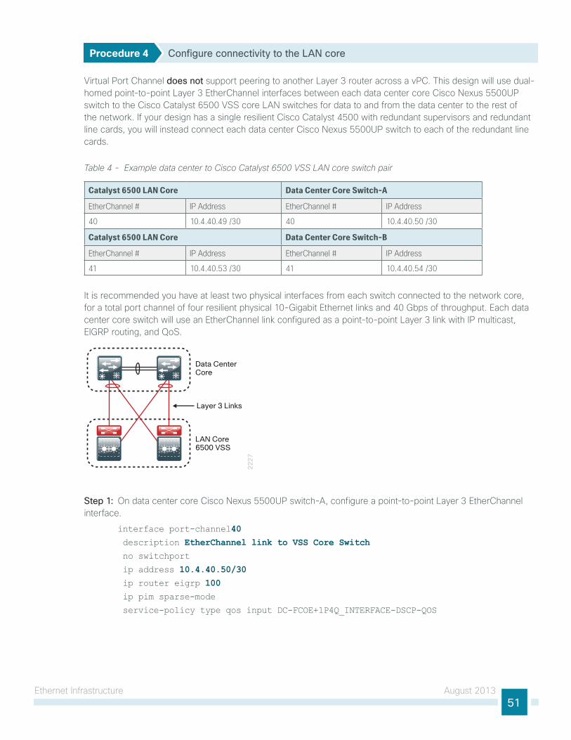
ethernet infrastructure August 201351
Procedure 4 Configure connectivity to the LAN core
Virtual Port Channel does not support peering to another layer 3 router across a vPC. this design will use dual-homed point-to-point layer 3 etherChannel interfaces between each data center core Cisco nexus 5500uP switch to the Cisco Catalyst 6500 Vss core lAn switches for data to and from the data center to the rest of the network. if your design has a single resilient Cisco Catalyst 4500 with redundant supervisors and redundant line cards, you will instead connect each data center Cisco nexus 5500uP switch to each of the redundant line cards.
Table 4 - Example data center to Cisco Catalyst 6500 VSS LAN core switch pair
Catalyst 6500 LAN Core Data Center Core Switch-A
EtherChannel # IP Address EtherChannel # IP Address
40 10.4.40.49 /30 40 10.4.40.50 /30
Catalyst 6500 LAN Core Data Center Core Switch-B
EtherChannel # IP Address EtherChannel # IP Address
41 10.4.40.53 /30 41 10.4.40.54 /30
it is recommended you have at least two physical interfaces from each switch connected to the network core, for a total port channel of four resilient physical 10-gigabit ethernet links and 40 gbps of throughput. each data center core switch will use an etherChannel link configured as a point-to-point layer 3 link with iP multicast, eigRP routing, and Qos.
22
27
Data Center Core
LAN Core 6500 VSS
Layer 3 Links
Step 1: on data center core Cisco nexus 5500uP switch-A, configure a point-to-point layer 3 etherChannel interface.
interface port-channel40 description EtherChannel link to VSS Core Switch no switchport
ip address 10.4.40.50/30 ip router eigrp 100 ip pim sparse-mode
service-policy type qos input DC-FCOE+1P4Q_INTERFACE-DSCP-QOS
ethernet infrastructure August 201352
Step 2: on data center core Cisco nexus 5500uP switch-A, configure the physical interfaces that belong to the etherChannel interface.
interface Ethernet1/19 description EtherChannel link to VSS Core Switch Te1/4/7 channel-group 40 mode active no shutdown
interface Ethernet1/20 description EtherChannel link to VSS Core Switch Te2/4/7 channel-group 40 mode active no shutdown
Step 3: on data center core Cisco nexus 5500uP switch-B, configure a point-to-point layer 3 etherChannel interface.
interface port-channel41 description EtherChannel link to VSS Core Switch no switchport
ip address 10.4.40.54/30 ip router eigrp 100 ip pim sparse-mode
service-policy type qos input DC-FCOE+1P4Q_INTERFACE-DSCP-QOS
Step 4: on data center core Cisco nexus 5500uP switch-B, configure the physical interfaces that belong to the etherChannel interface.
interface Ethernet1/19 description EtherChannel link to VSS Core Switch Te1/4/8 channel-group 41 mode active no shutdown
interface Ethernet1/20 description EtherChannel link to VSS Core Switch Te2/4/8 channel-group 41 mode active no shutdown
ethernet infrastructure August 201353
Step 5: on the Cisco lAn Core 6500 Vss switch pair, configure a corresponding point-to-point layer 3 etherChannel to Data Center switch-A.
• Configure the layer 3 etherChannel interface.
interface Port-channel40 description EtherChannel link to Data Center Switch DC5500-A no switchport
ip address 10.4.40.49 255.255.255.252 ip pim sparse-mode
no shutdown
• Configure the physical interfaces that belong to the etherChannel interface.
interface TenGigabitEthernet1/4/7 description EtherChannel link to DC Switch 5500-A eth1/19 no switchport
no ip address
logging event link-status
logging event trunk-status
logging event bundle-status
carrier-delay msec 0
macro apply EgressQoSTenOrFortyGig
channel-group 40 mode active no shutdown
!
interface TenGigabitEthernet2/4/7 description EtherChannel link to DC Switch 5500-A eth1/20 no switchport
no ip address
logging event link-status
logging event trunk-status
logging event bundle-status
carrier-delay msec 0
macro apply EgressQoSTenOrFortyGig
channel-group 40 mode active no shutdown
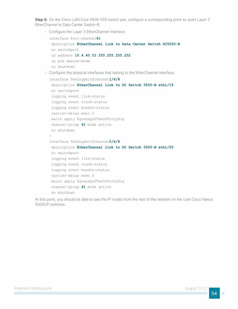
ethernet infrastructure August 201354
Step 6: on the Cisco lAn Core 6500 Vss switch pair, configure a corresponding point-to-point layer 3 etherChannel to Data Center switch-B.
• Configure the layer 3 etherChannel interface.
interface Port-channel41 description EtherChannel link to Data Center Switch DC5500-B no switchport
ip address 10.4.40.53 255.255.255.252 ip pim sparse-mode
no shutdown
• Configure the physical interfaces that belong to the etherChannel interface.
interface TenGigabitEthernet1/4/8 description EtherChannel link to DC Switch 5500-B eth1/19 no switchport
logging event link-status
logging event trunk-status
logging event bundle-status
carrier-delay msec 0
macro apply EgressQoSTenOrFortyGig
channel-group 41 mode active no shutdown
!
interface TenGigabitEthernet2/4/8 description EtherChannel link to DC Switch 5500-B eth1/20 no switchport
logging event link-status
logging event trunk-status
logging event bundle-status
carrier-delay msec 0
macro apply EgressQoSTenOrFortyGig
channel-group 41 mode active no shutdown
At this point, you should be able to see the iP routes from the rest of the network on the core Cisco nexus 5500uP switches.
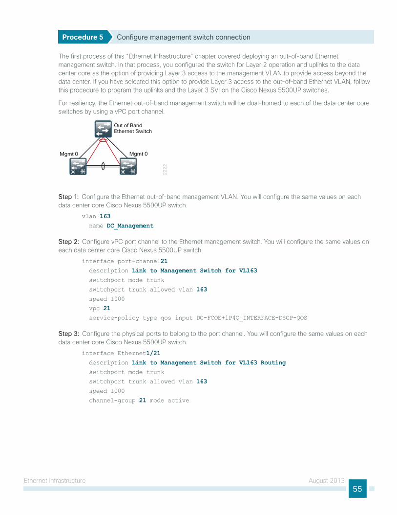
ethernet infrastructure August 201355
Procedure 5 Configure management switch connection
the first process of this “ethernet infrastructure” chapter covered deploying an out-of-band ethernet management switch. in that process, you configured the switch for layer 2 operation and uplinks to the data center core as the option of providing layer 3 access to the management VlAn to provide access beyond the data center. if you have selected this option to provide layer 3 access to the out-of-band ethernet VlAn, follow this procedure to program the uplinks and the layer 3 sVi on the Cisco nexus 5500uP switches.
For resiliency, the ethernet out-of-band management switch will be dual-homed to each of the data center core switches by using a vPC port channel.
22
22
Mgmt 0 Mgmt 0
Out of BandEthernet Switch
Step 1: Configure the ethernet out-of-band management VlAn. you will configure the same values on each data center core Cisco nexus 5500uP switch.
vlan 163 name DC_Management
Step 2: Configure vPC port channel to the ethernet management switch. you will configure the same values on each data center core Cisco nexus 5500uP switch.
interface port-channel21 description Link to Management Switch for VL163 switchport mode trunk
switchport trunk allowed vlan 163 speed 1000
vpc 21 service-policy type qos input DC-FCOE+1P4Q_INTERFACE-DSCP-QOS
Step 3: Configure the physical ports to belong to the port channel. you will configure the same values on each data center core Cisco nexus 5500uP switch.
interface Ethernet1/21 description Link to Management Switch for VL163 Routing switchport mode trunk switchport trunk allowed vlan 163 speed 1000
channel-group 21 mode active
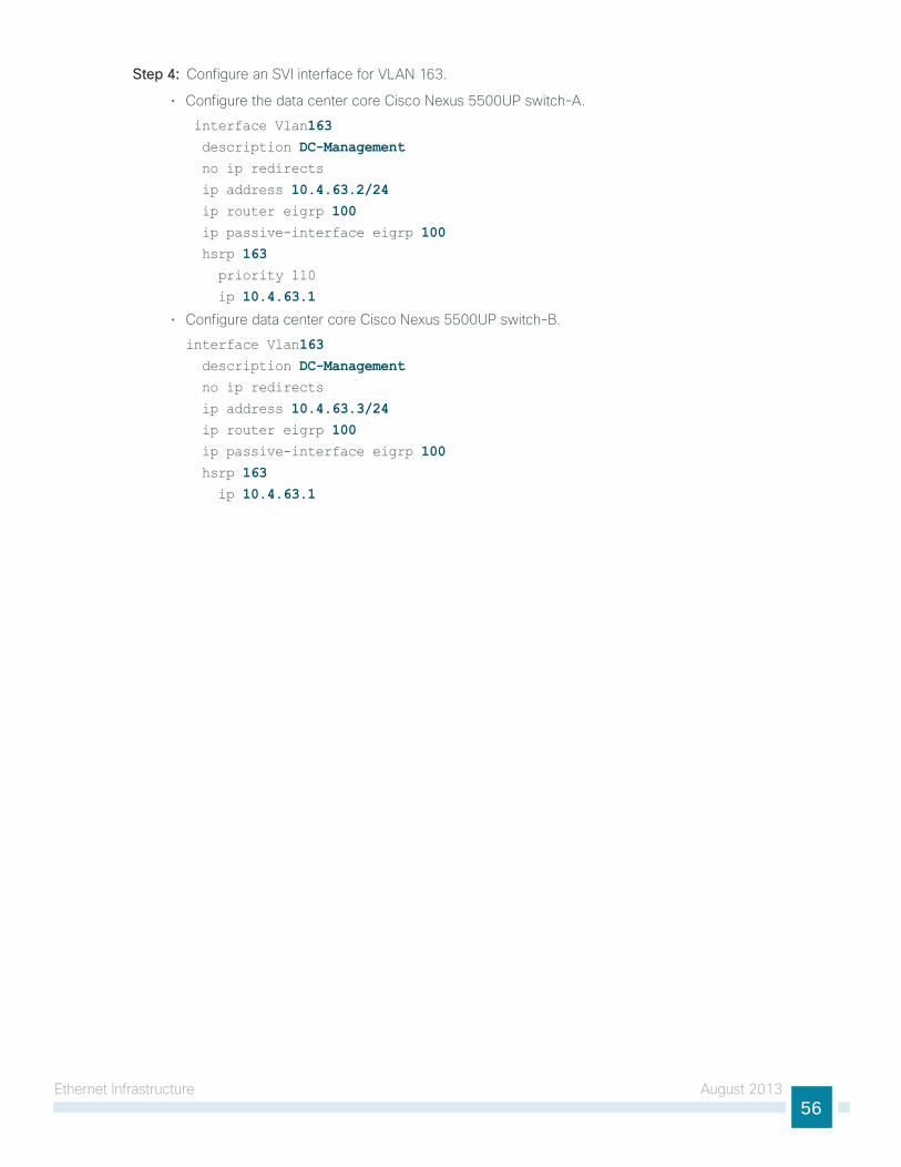
ethernet infrastructure August 201356
Step 4: Configure an sVi interface for VlAn 163.
• Configure the data center core Cisco nexus 5500uP switch-A.
interface Vlan163 description DC-Management no ip redirects
ip address 10.4.63.2/24 ip router eigrp 100 ip passive-interface eigrp 100 hsrp 163 priority 110
ip 10.4.63.1
• Configure data center core Cisco nexus 5500uP switch-B.
interface Vlan163 description DC-Management no ip redirects
ip address 10.4.63.3/24 ip router eigrp 100 ip passive-interface eigrp 100 hsrp 163 ip 10.4.63.1
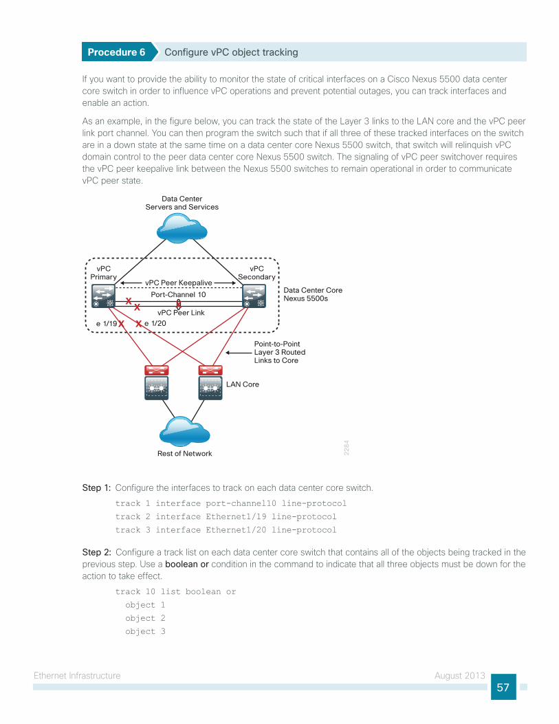
ethernet infrastructure August 201357
Procedure 6 Configure vPC object tracking
if you want to provide the ability to monitor the state of critical interfaces on a Cisco nexus 5500 data center core switch in order to influence vPC operations and prevent potential outages, you can track interfaces and enable an action.
As an example, in the figure below, you can track the state of the layer 3 links to the lAn core and the vPC peer link port channel. you can then program the switch such that if all three of these tracked interfaces on the switch are in a down state at the same time on a data center core nexus 5500 switch, that switch will relinquish vPC domain control to the peer data center core nexus 5500 switch. the signaling of vPC peer switchover requires the vPC peer keepalive link between the nexus 5500 switches to remain operational in order to communicate vPC peer state.
22
84
vPCPrimary
vPCSecondary
vPC Peer Keepalive
vPC Peer Link
e 1/20e 1/19
Port-Channel 10Data Center CoreNexus 5500s
Point-to-PointLayer 3 Routed Links to Core
LAN Core
Rest of Network
Data CenterServers and Services
X
X X
XX
Step 1: Configure the interfaces to track on each data center core switch.
track 1 interface port-channel10 line-protocol
track 2 interface Ethernet1/19 line-protocol
track 3 interface Ethernet1/20 line-protocol
Step 2: Configure a track list on each data center core switch that contains all of the objects being tracked in the previous step. use a boolean or condition in the command to indicate that all three objects must be down for the action to take effect.
track 10 list boolean or
object 1
object 2
object 3
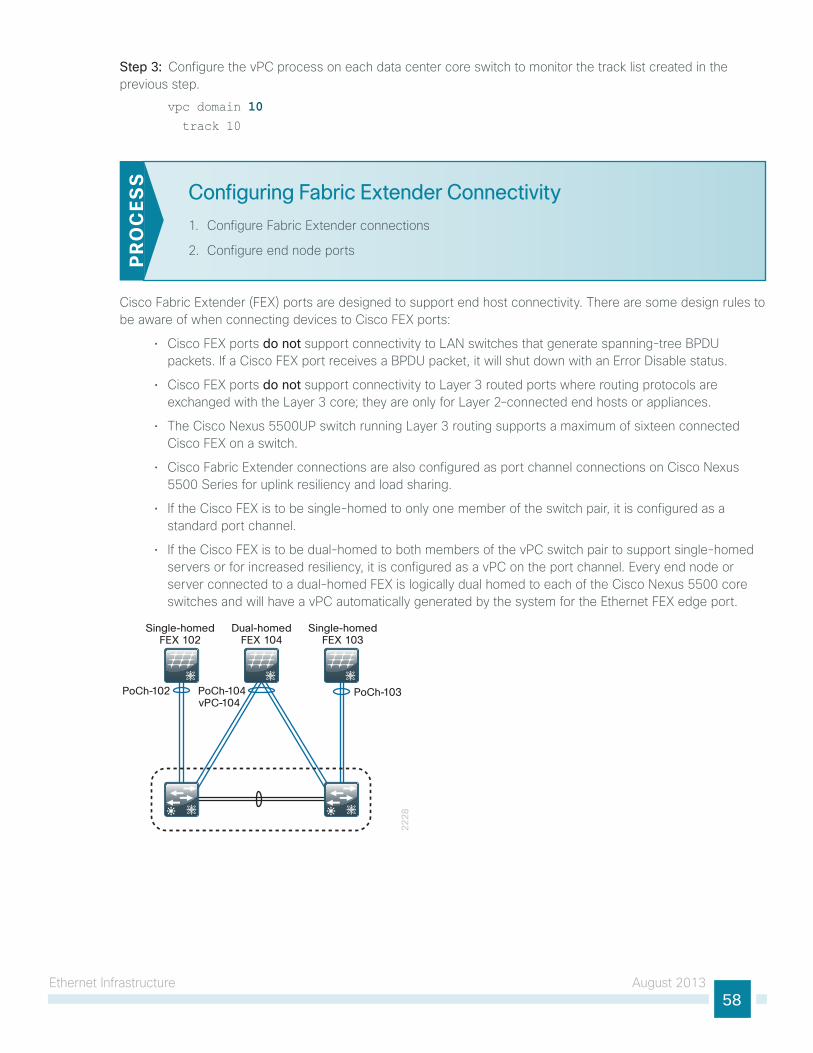
ethernet infrastructure August 201358
Step 3: Configure the vPC process on each data center core switch to monitor the track list created in the previous step.
vpc domain 10 track 10
Configuring Fabric Extender Connectivity
1. Configure Fabric extender connections
2. Configure end node portsPR
OC
ESS
Cisco Fabric extender (FeX) ports are designed to support end host connectivity. there are some design rules to be aware of when connecting devices to Cisco FeX ports:
• Cisco FeX ports do not support connectivity to lAn switches that generate spanning-tree BPDu packets. if a Cisco FeX port receives a BPDu packet, it will shut down with an error Disable status.
• Cisco FeX ports do not support connectivity to layer 3 routed ports where routing protocols are exchanged with the layer 3 core; they are only for layer 2–connected end hosts or appliances.
• the Cisco nexus 5500uP switch running layer 3 routing supports a maximum of sixteen connected Cisco FeX on a switch.
• Cisco Fabric extender connections are also configured as port channel connections on Cisco nexus 5500 series for uplink resiliency and load sharing.
• if the Cisco FeX is to be single-homed to only one member of the switch pair, it is configured as a standard port channel.
• if the Cisco FeX is to be dual-homed to both members of the vPC switch pair to support single-homed servers or for increased resiliency, it is configured as a vPC on the port channel. every end node or server connected to a dual-homed FeX is logically dual homed to each of the Cisco nexus 5500 core switches and will have a vPC automatically generated by the system for the ethernet FeX edge port.
22
28
Single-homedFEX 102
PoCh-102 PoCh-104vPC-104
PoCh-103
Dual-homedFEX 104
Single-homedFEX 103
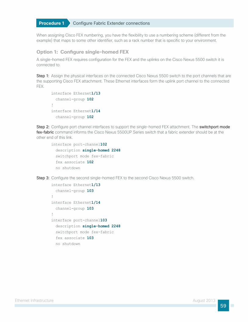
ethernet infrastructure August 201359
Procedure 1 Configure Fabric Extender connections
When assigning Cisco FeX numbering, you have the flexibility to use a numbering scheme (different from the example) that maps to some other identifier, such as a rack number that is specific to your environment.
Option 1: Configure single-homed FEXA single-homed FeX requires configuration for the FeX and the uplinks on the Cisco nexus 5500 switch it is connected to.
Step 1: Assign the physical interfaces on the connected Cisco nexus 5500 switch to the port channels that are the supporting Cisco FeX attachment. these ethernet interfaces form the uplink port channel to the connected FeX.
interface Ethernet1/13 channel-group 102!
interface Ethernet1/14 channel-group 102
Step 2: Configure port channel interfaces to support the single-homed FeX attachment. the switchport mode fex-fabric command informs the Cisco nexus 5500uP series switch that a fabric extender should be at the other end of this link.
interface port-channel102 description single-homed 2248 switchport mode fex-fabric
fex associate 102 no shutdown
Step 3: Configure the second single-homed FeX to the second Cisco nexus 5500 switch.
interface Ethernet1/13 channel-group 103!
interface Ethernet1/14 channel-group 103 !
interface port-channel103 description single-homed 2248 switchport mode fex-fabric
fex associate 103 no shutdown
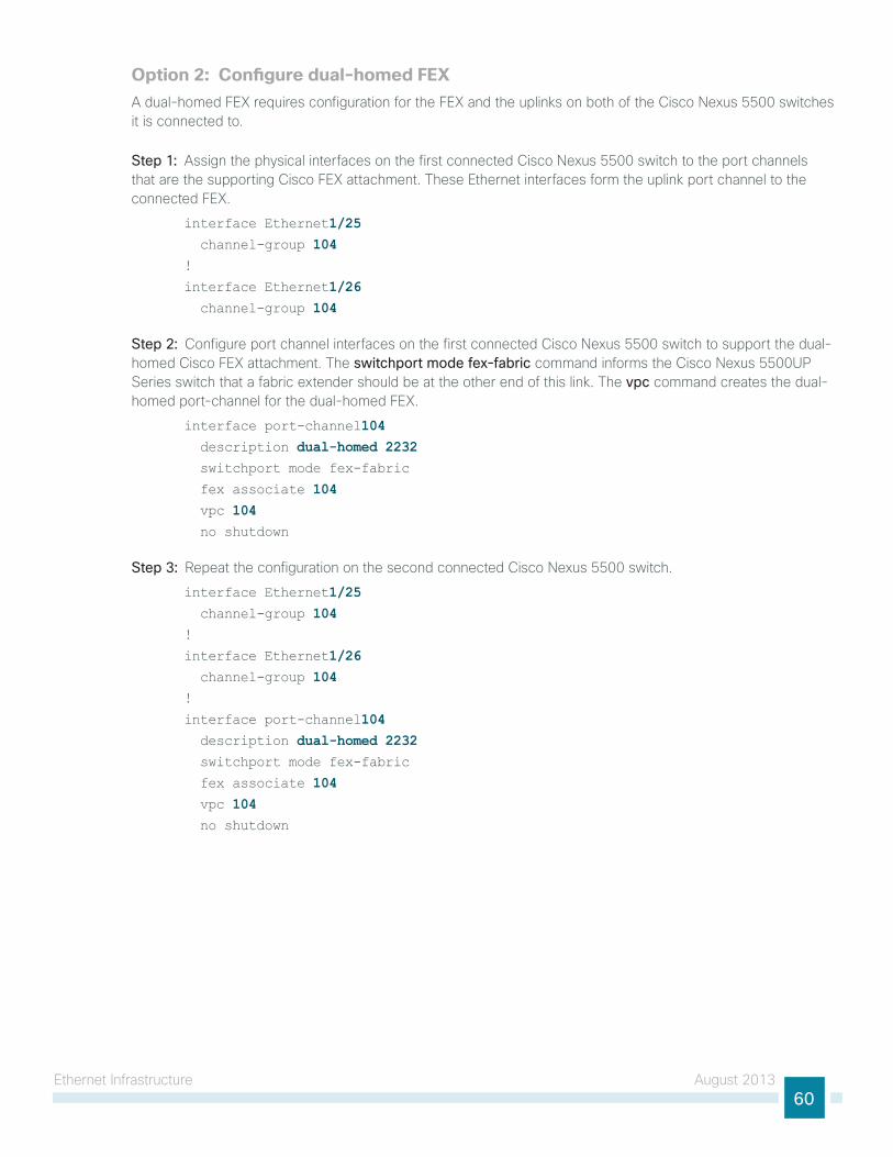
ethernet infrastructure August 201360
Option 2: Configure dual-homed FEXA dual-homed FeX requires configuration for the FeX and the uplinks on both of the Cisco nexus 5500 switches it is connected to.
Step 1: Assign the physical interfaces on the first connected Cisco nexus 5500 switch to the port channels that are the supporting Cisco FeX attachment. these ethernet interfaces form the uplink port channel to the connected FeX.
interface Ethernet1/25 channel-group 104!
interface Ethernet1/26 channel-group 104
Step 2: Configure port channel interfaces on the first connected Cisco nexus 5500 switch to support the dual-homed Cisco FeX attachment. the switchport mode fex-fabric command informs the Cisco nexus 5500uP series switch that a fabric extender should be at the other end of this link. the vpc command creates the dual-homed port-channel for the dual-homed FeX.
interface port-channel104 description dual-homed 2232 switchport mode fex-fabric
fex associate 104 vpc 104 no shutdown
Step 3: Repeat the configuration on the second connected Cisco nexus 5500 switch.
interface Ethernet1/25 channel-group 104!
interface Ethernet1/26 channel-group 104!
interface port-channel104 description dual-homed 2232 switchport mode fex-fabric
fex associate 104 vpc 104 no shutdown
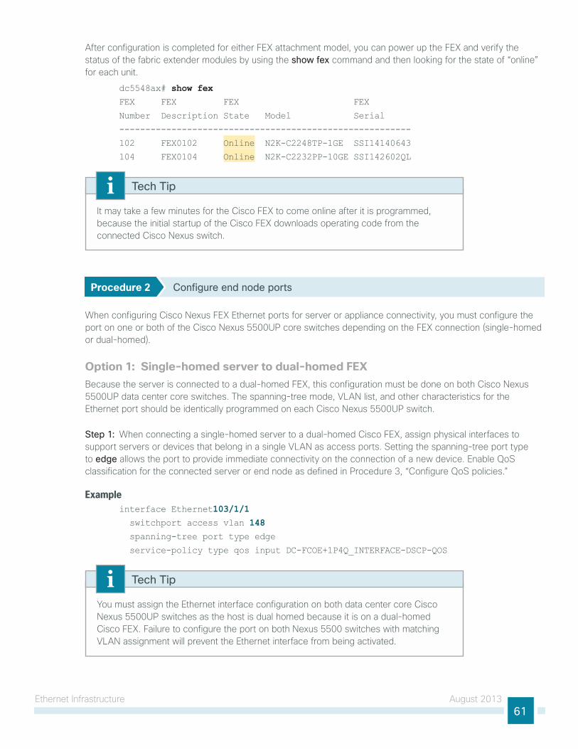
ethernet infrastructure August 201361
After configuration is completed for either FeX attachment model, you can power up the FeX and verify the status of the fabric extender modules by using the show fex command and then looking for the state of “online” for each unit.
dc5548ax# show fexFEX FEX FEX FEX
Number Description State Model Serial
--------------------------------------------------------
102 FEX0102 Online N2K-C2248TP-1GE SSI14140643
104 FEX0104 Online N2K-C2232PP-10GE SSI142602QL
it may take a few minutes for the Cisco FeX to come online after it is programmed, because the initial startup of the Cisco FeX downloads operating code from the connected Cisco nexus switch.
Tech Tip
Procedure 2 Configure end node ports
When configuring Cisco nexus FeX ethernet ports for server or appliance connectivity, you must configure the port on one or both of the Cisco nexus 5500uP core switches depending on the FeX connection (single-homed or dual-homed).
Option 1: Single-homed server to dual-homed FEXBecause the server is connected to a dual-homed FeX, this configuration must be done on both Cisco nexus 5500uP data center core switches. the spanning-tree mode, VlAn list, and other characteristics for the ethernet port should be identically programmed on each Cisco nexus 5500uP switch.
Step 1: When connecting a single-homed server to a dual-homed Cisco FeX, assign physical interfaces to support servers or devices that belong in a single VlAn as access ports. setting the spanning-tree port type to edge allows the port to provide immediate connectivity on the connection of a new device. enable Qos classification for the connected server or end node as defined in Procedure 3, “Configure Qos policies.”
Exampleinterface Ethernet103/1/1 switchport access vlan 148 spanning-tree port type edge
service-policy type qos input DC-FCOE+1P4Q_INTERFACE-DSCP-QOS
you must assign the ethernet interface configuration on both data center core Cisco nexus 5500uP switches as the host is dual homed because it is on a dual-homed Cisco FeX. Failure to configure the port on both nexus 5500 switches with matching VlAn assignment will prevent the ethernet interface from being activated.
Tech Tip
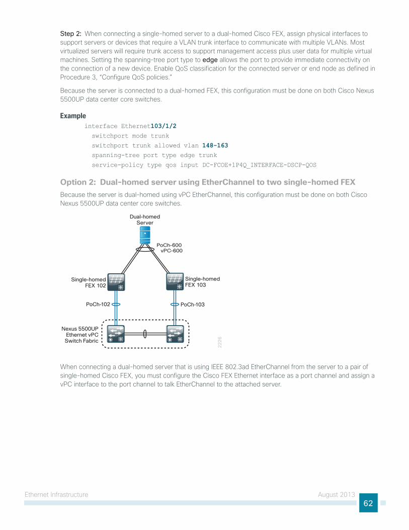
ethernet infrastructure August 201362
Step 2: When connecting a single-homed server to a dual-homed Cisco FeX, assign physical interfaces to support servers or devices that require a VlAn trunk interface to communicate with multiple VlAns. Most virtualized servers will require trunk access to support management access plus user data for multiple virtual machines. setting the spanning-tree port type to edge allows the port to provide immediate connectivity on the connection of a new device. enable Qos classification for the connected server or end node as defined in Procedure 3, “Configure Qos policies.”
Because the server is connected to a dual-homed FeX, this configuration must be done on both Cisco nexus 5500uP data center core switches.
Exampleinterface Ethernet103/1/2 switchport mode trunk
switchport trunk allowed vlan 148-163 spanning-tree port type edge trunk
service-policy type qos input DC-FCOE+1P4Q_INTERFACE-DSCP-QOS
Option 2: Dual-homed server using EtherChannel to two single-homed FEXBecause the server is dual-homed using vPC etherChannel, this configuration must be done on both Cisco nexus 5500uP data center core switches.
22
26
Single-homedFEX 102
Single-homedFEX 103
PoCh-102
Nexus 5500UPEthernet vPC
Switch Fabric
PoCh-103
PoCh-600 vPC-600
Dual-homedServer
When connecting a dual-homed server that is using ieee 802.3ad etherChannel from the server to a pair of single-homed Cisco FeX, you must configure the Cisco FeX ethernet interface as a port channel and assign a vPC interface to the port channel to talk etherChannel to the attached server.
ethernet infrastructure August 201363
ExampleStep 1: on Cisco nexus 5500 switch-A.
interface ethernet102/1/1-2 switchport mode trunk
switchport trunk allowed vlan 148-163 spanning-tree port type edge trunk
channel-group 600 no shutdown
interface port-channel 600 service-policy type qos input DC-FCOE+1P4Q_INTERFACE-DSCP-QOS
vpc 600 no shutdown
Step 2: on Cisco nexus 5500 switch-B.
interface ethernet103/1/1-2 switchport mode trunk
switchport trunk allowed vlan 148-163 spanning-tree port type edge trunk
channel-group 600 no shutdown
interface port-channel 600 service-policy type qos input DC-FCOE+1P4Q_INTERFACE-DSCP-QOS
vpc 600 no shutdown
When connecting ports via vPC, Cisco nX-os does consistency checks to make sure that the VlAn list, spanning-tree mode, and other characteristics match between the ports configured on each switch that make up a vPC. if the configuration for each port is not identical with the other, the port will not come up.
Tech Tip
Option 3: Dual-homed server using EtherChannel to two dual-homed FEXthis connectivity option, referred to as enhanced vPC, requires Cisco nX-os release 5.1(3)n1(1) or later for the Cisco nexus 5500 switches. Dual-homing a server with etherChannel to a dual-homed FeX is not supported on the older Cisco nexus 5000 switches.
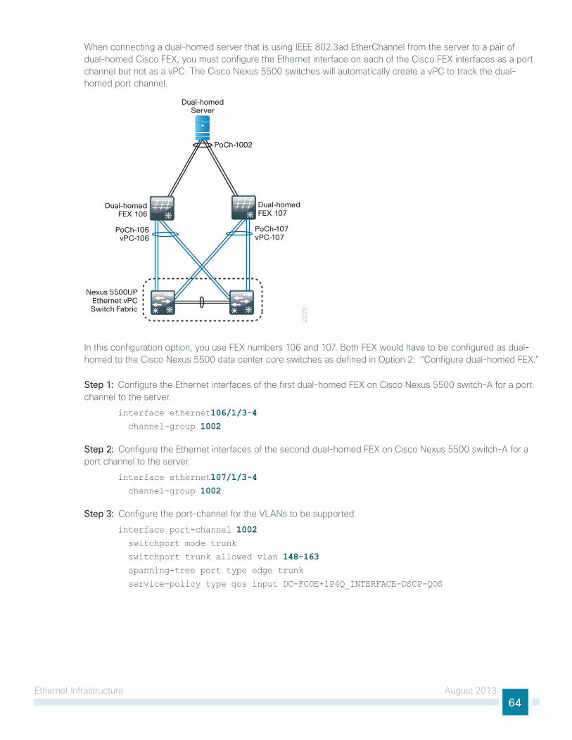
ethernet infrastructure August 201364
When connecting a dual-homed server that is using ieee 802.3ad etherChannel from the server to a pair of dual-homed Cisco FeX, you must configure the ethernet interface on each of the Cisco FeX interfaces as a port channel but not as a vPC. the Cisco nexus 5500 switches will automatically create a vPC to track the dual-homed port channel.
22
29
Dual-homedFEX 106
Dual-homedFEX 107
PoCh-106vPC-106
Nexus 5500UPEthernet vPC
Switch Fabric
PoCh-107vPC-107
PoCh-1002
Dual-homedServer
in this configuration option, you use FeX numbers 106 and 107. Both FeX would have to be configured as dual-homed to the Cisco nexus 5500 data center core switches as defined in option 2: “Configure dual-homed FeX.”
Step 1: Configure the ethernet interfaces of the first dual-homed FeX on Cisco nexus 5500 switch-A for a port channel to the server.
interface ethernet106/1/3-4 channel-group 1002
Step 2: Configure the ethernet interfaces of the second dual-homed FeX on Cisco nexus 5500 switch-A for a port channel to the server.
interface ethernet107/1/3-4 channel-group 1002
Step 3: Configure the port-channel for the VlAns to be supported.
interface port-channel 1002 switchport mode trunk
switchport trunk allowed vlan 148-163 spanning-tree port type edge trunk
service-policy type qos input DC-FCOE+1P4Q_INTERFACE-DSCP-QOS
ethernet infrastructure August 201365
Step 4: Repeat the commands on Cisco nexus 5500 switch-B with the same settings, because the server and the FeX are dual-homed.
interface ethernet106/1/3-4 channel-group 1002!
interface ethernet107/1/3-4 channel-group 1002!
interface port-channel 1002 switchport mode trunk
switchport trunk allowed vlan 148-163 spanning-tree port type edge trunk
service-policy type qos input DC-FCOE+1P4Q_INTERFACE-DSCP-QOS
storage infrastructure August 201366
storage infrastructure
Design OverviewIP-based Storage Options
Many storage systems provide the option for access using iP over the ethernet network. this approach allows a growing organization to gain the advantages of centralized storage without needing to deploy and administer a separate Fibre Channel network. options for iP-based storage connectivity include internet small Computer system interface (isCsi) and network attached storage (nAs).
isCsi is a protocol that enables servers to connect to storage over an iP connection and is a lower-cost alternative to Fibre Channel. isCsi services on the server must contend for CPu and bandwidth along with other network applications, so you need to ensure that the processing requirements and performance are suitable for a specific application. isCsi has become a storage technology that is supported by most server, storage, and application vendors. isCsi provides block-level storage access to raw disk resources, similar to Fibre Channel. niCs also can provide support to offload isCsi to a separate processor to increase performance.
Network attached storage (NAS) is a general term used to refer to a group of common file access protocols, the most common implementations use Common internet File system (CiFs) or network file server (nFs). CiFs originated in the Microsoft network environment and is a common desktop file-sharing protocol. nFs is a multi-platform protocol that originated in the uniX environment and can be used for shared hypervisor storage. Both nAs protocols provide file-level access to shared storage resources.
Most organizations will have applications for multiple storage access technologies—for example, Fibre Channel for the high performance database and production servers, and nAs for desktop storage access.
Fibre Channel StorageFibre Channel allows servers to connect to storage across a fiber-optic network, across a data center, or even across a WAn by using Fibre Channel over iP. Multiple servers can share a single storage array.
this data center design uses the Cisco nexus 5500uP series switches as the core that provides Fibre Channel and Fibre Channel over ethernet (FCoe) sAn switching. the Cisco nexus 5500uP offers the density required for collapsed Fibre Channel connectivity requirements by supporting both Fibre Channel and FCoe servers and storage arrays. the Cisco MDs 9148 Multilayer Fabric switch is ideal for a larger sAn fabric with up to 48 Fibre Channel ports, providing 48 line-rate 8-gbps Fibre Channel ports and cost-effective scalability. the Cisco MDs family of Multilayer sAn Fabric switches also offers options like hardware-based encryption services, tape acceleration, and Fibre Channel over iP for longer distance sAn extension.
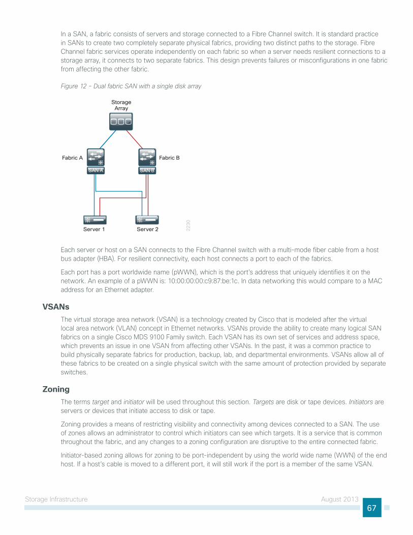
storage infrastructure August 201367
in a sAn, a fabric consists of servers and storage connected to a Fibre Channel switch. it is standard practice in sAns to create two completely separate physical fabrics, providing two distinct paths to the storage. Fibre Channel fabric services operate independently on each fabric so when a server needs resilient connections to a storage array, it connects to two separate fabrics. this design prevents failures or misconfigurations in one fabric from affecting the other fabric.
Figure 12 - Dual fabric SAN with a single disk array
22
30
Server 1 Server 2
StorageArray
Fabric A Fabric B
SAN BSAN BSAN A
each server or host on a sAn connects to the Fibre Channel switch with a multi-mode fiber cable from a host bus adapter (hBA). For resilient connectivity, each host connects a port to each of the fabrics.
each port has a port worldwide name (pWWn), which is the port’s address that uniquely identifies it on the network. An example of a pWWn is: 10:00:00:00:c9:87:be:1c. in data networking this would compare to a MAC address for an ethernet adapter.
VSANsthe virtual storage area network (VsAn) is a technology created by Cisco that is modeled after the virtual local area network (VlAn) concept in ethernet networks. VsAns provide the ability to create many logical sAn fabrics on a single Cisco MDs 9100 Family switch. each VsAn has its own set of services and address space, which prevents an issue in one VsAn from affecting other VsAns. in the past, it was a common practice to build physically separate fabrics for production, backup, lab, and departmental environments. VsAns allow all of these fabrics to be created on a single physical switch with the same amount of protection provided by separate switches.
Zoning the terms target and initiator will be used throughout this section. Targets are disk or tape devices. Initiators are servers or devices that initiate access to disk or tape.
Zoning provides a means of restricting visibility and connectivity among devices connected to a sAn. the use of zones allows an administrator to control which initiators can see which targets. it is a service that is common throughout the fabric, and any changes to a zoning configuration are disruptive to the entire connected fabric.
initiator-based zoning allows for zoning to be port-independent by using the world wide name (WWn) of the end host. if a host’s cable is moved to a different port, it will still work if the port is a member of the same VsAn.
storage infrastructure August 201368
Device Aliases When configuring features such as zoning, quality of service (Qos), and port security on a Cisco MDs 9000 Family switch, WWns must be specified. the WWn naming format is cumbersome, and manually typing WWns is error prone. Device aliases provide a user-friendly naming format for WWns in the sAn fabric (for example: “p3-c210-1-hba0-a” instead of “10:00:00:00:c9:87:be:1c”).
use a naming convention that makes initiator and target identification easy. For example, p3-c210-1-hba0-a in this setup identifies:
• Rack location: p3
• host type: c210
• host number: 1
• hBA number: hba0
• Port on hBA: a
Storage Array Tested the storage arrays used in the testing and validation of this design guide are the eMC VnX-5300 and the netApp FAs3200. the specific storage array configuration may vary. Please consult the installation instructions from the specific storage vendor. the Cisco interoperability support matrix for Fibre Channel host bus adapters and storage arrays can be found at:
http://www.cisco.com/en/us/docs/switches/datacenter/mds9000/interoperability/matrix/intmatrx.html
specific interfaces, addresses, and device aliases are examples from the lab. your WWn addresses, interfaces, and device aliases will likely be different.
Tech Tip
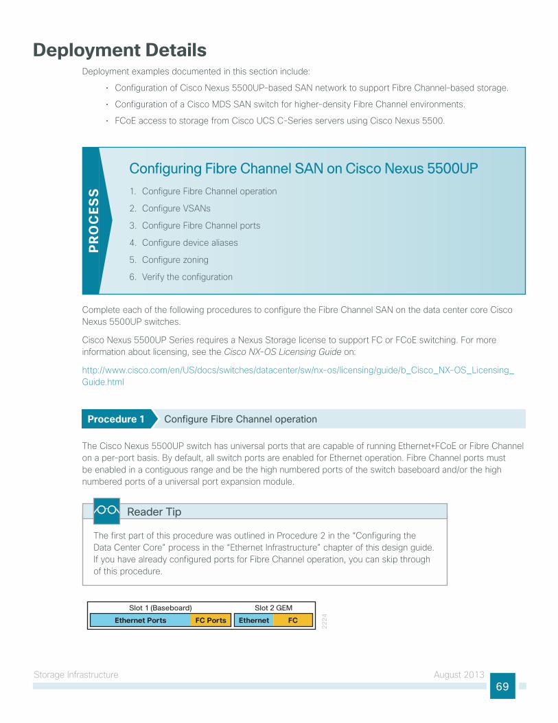
storage infrastructure August 201369
Deployment DetailsDeployment examples documented in this section include:
• Configuration of Cisco nexus 5500uP–based sAn network to support Fibre Channel–based storage.
• Configuration of a Cisco MDs sAn switch for higher-density Fibre Channel environments.
• FCoe access to storage from Cisco uCs C-series servers using Cisco nexus 5500.
Configuring Fibre Channel SAN on Cisco Nexus 5500UP
1. Configure Fibre Channel operation
2. Configure VsAns
3. Configure Fibre Channel ports
4. Configure device aliases
5. Configure zoning
6. Verify the configuration
PR
OC
ESS
Complete each of the following procedures to configure the Fibre Channel sAn on the data center core Cisco nexus 5500uP switches.
Cisco nexus 5500uP series requires a nexus storage license to support FC or FCoe switching. For more information about licensing, see the Cisco NX-OS Licensing Guide on:
http://www.cisco.com/en/us/docs/switches/datacenter/sw/nx-os/licensing/guide/b_Cisco_nX-os_licensing_guide.html
Procedure 1 Configure Fibre Channel operation
the Cisco nexus 5500uP switch has universal ports that are capable of running ethernet+FCoe or Fibre Channel on a per-port basis. By default, all switch ports are enabled for ethernet operation. Fibre Channel ports must be enabled in a contiguous range and be the high numbered ports of the switch baseboard and/or the high numbered ports of a universal port expansion module.
the first part of this procedure was outlined in Procedure 2 in the “Configuring the Data Center Core” process in the “ethernet infrastructure” chapter of this design guide. if you have already configured ports for Fibre Channel operation, you can skip through of this procedure.
Reader Tip
22
24
Slot 1 (Baseboard) Slot 2 GEM
Ethernet Ports FC Ports Ethernet FC
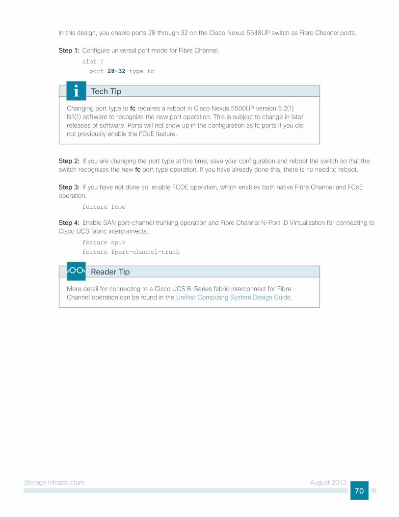
storage infrastructure August 201370
in this design, you enable ports 28 through 32 on the Cisco nexus 5548uP switch as Fibre Channel ports.
Step 1: Configure universal port mode for Fibre Channel.
slot 1
port 28-32 type fc
Changing port type to fc requires a reboot in Cisco nexus 5500uP version 5.2(1)n1(1) software to recognize the new port operation. this is subject to change in later releases of software. Ports will not show up in the configuration as fc ports if you did not previously enable the FCoe feature.
Tech Tip
Step 2: if you are changing the port type at this time, save your configuration and reboot the switch so that the switch recognizes the new fc port type operation. if you have already done this, there is no need to reboot.
Step 3: if you have not done so, enable FCoe operation, which enables both native Fibre Channel and FCoe operation.
feature fcoe
Step 4: enable sAn port-channel trunking operation and Fibre Channel n-Port iD Virtualization for connecting to Cisco uCs fabric interconnects.
feature npiv
feature fport-channel-trunk
More detail for connecting to a Cisco uCs B-series fabric interconnect for Fibre Channel operation can be found in the unified Computing system Design guide.
Reader Tip
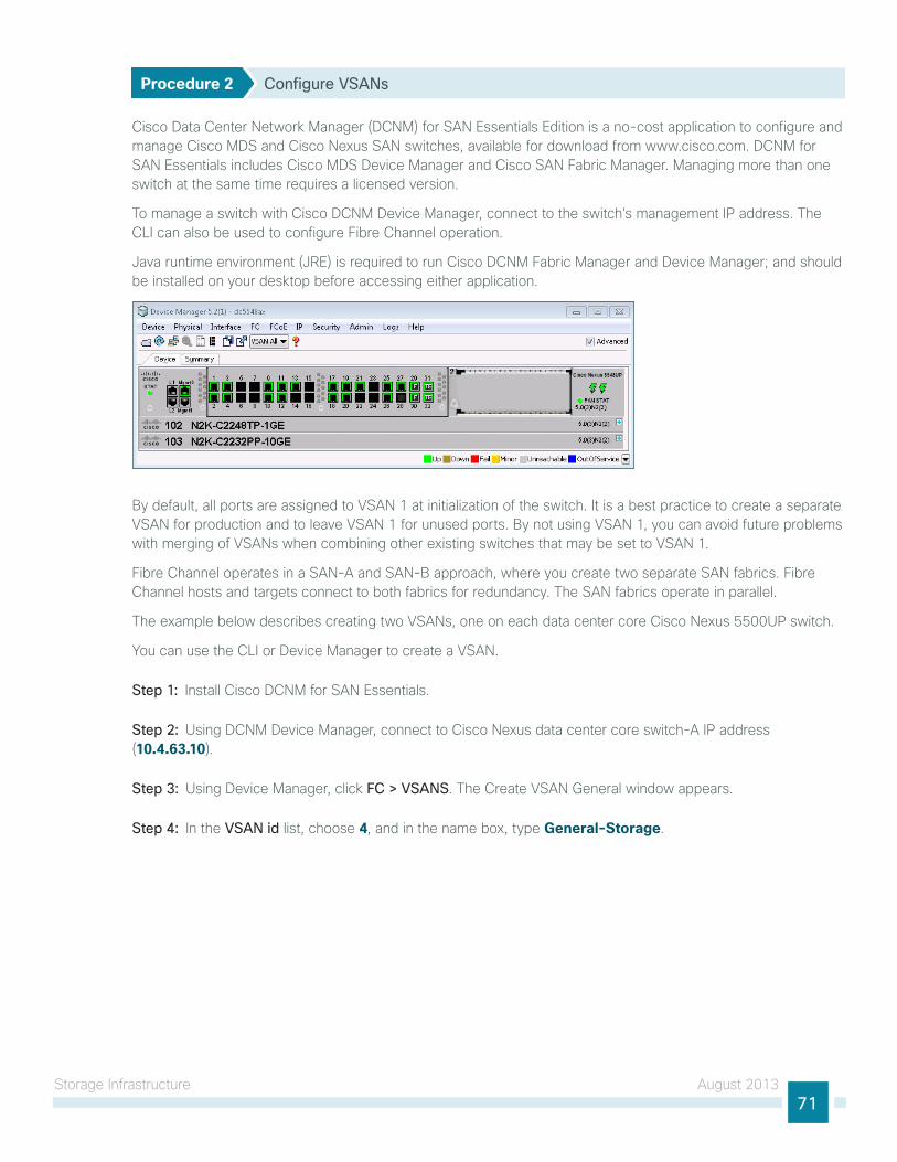
storage infrastructure August 201371
Procedure 2 Configure VSANs
Cisco Data Center network Manager (DCnM) for sAn essentials edition is a no-cost application to configure and manage Cisco MDs and Cisco nexus sAn switches, available for download from www.cisco.com. DCnM for sAn essentials includes Cisco MDs Device Manager and Cisco sAn Fabric Manager. Managing more than one switch at the same time requires a licensed version.
to manage a switch with Cisco DCnM Device Manager, connect to the switch’s management iP address. the Cli can also be used to configure Fibre Channel operation.
Java runtime environment (JRe) is required to run Cisco DCnM Fabric Manager and Device Manager; and should be installed on your desktop before accessing either application.
By default, all ports are assigned to VsAn 1 at initialization of the switch. it is a best practice to create a separate VsAn for production and to leave VsAn 1 for unused ports. By not using VsAn 1, you can avoid future problems with merging of VsAns when combining other existing switches that may be set to VsAn 1.
Fibre Channel operates in a sAn-A and sAn-B approach, where you create two separate sAn fabrics. Fibre Channel hosts and targets connect to both fabrics for redundancy. the sAn fabrics operate in parallel.
the example below describes creating two VsAns, one on each data center core Cisco nexus 5500uP switch.
you can use the Cli or Device Manager to create a VsAn.
Step 1: install Cisco DCnM for sAn essentials.
Step 2: using DCnM Device Manager, connect to Cisco nexus data center core switch-A iP address (10.4.63.10).
Step 3: using Device Manager, click FC > VSANS. the Create VsAn general window appears.
Step 4: in the VSAN id list, choose 4, and in the name box, type General-Storage.
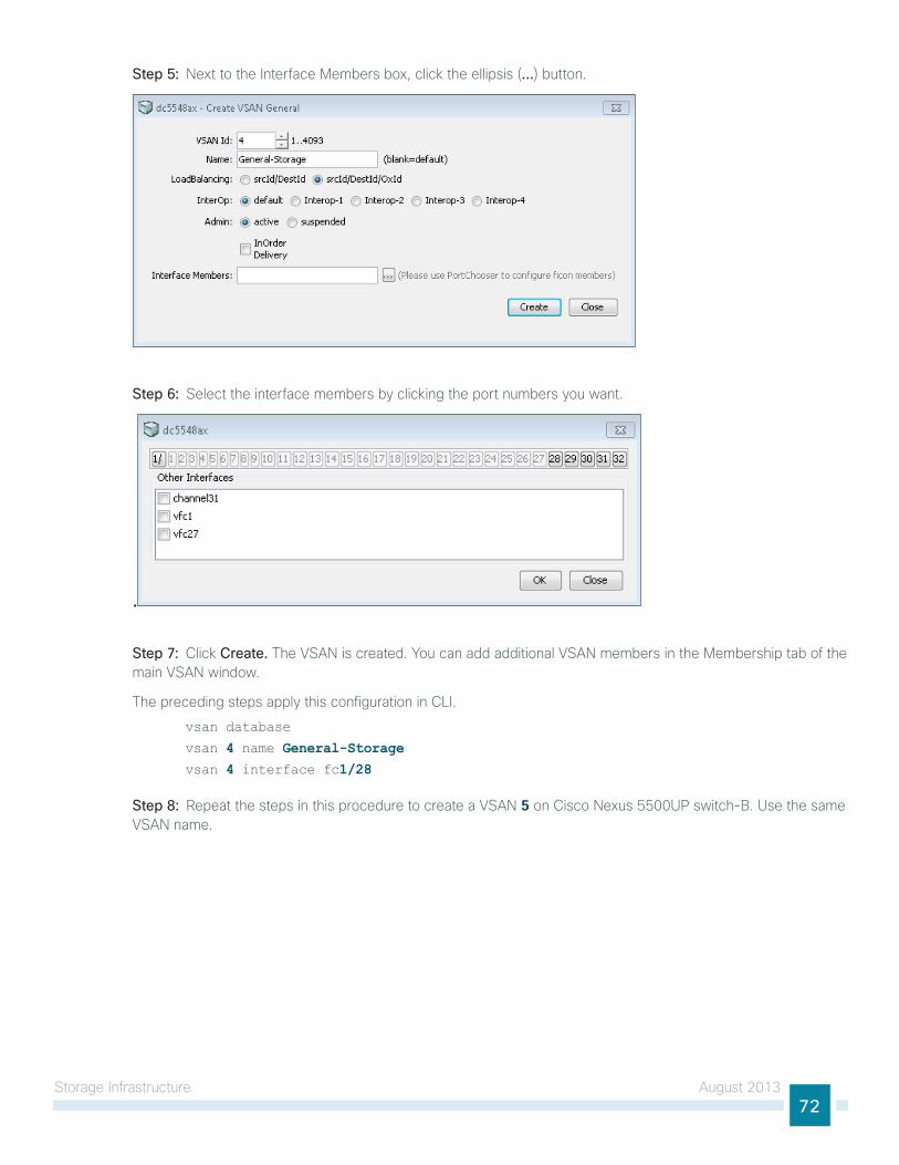
storage infrastructure August 201372
Step 5: next to the interface Members box, click the ellipsis (…) button.
Step 6: select the interface members by clicking the port numbers you want.
.
Step 7: Click Create. the VsAn is created. you can add additional VsAn members in the Membership tab of the main VsAn window.
the preceding steps apply this configuration in Cli.
vsan database
vsan 4 name General-Storage vsan 4 interface fc1/28
Step 8: Repeat the steps in this procedure to create a VsAn 5 on Cisco nexus 5500uP switch-B. use the same VsAn name.
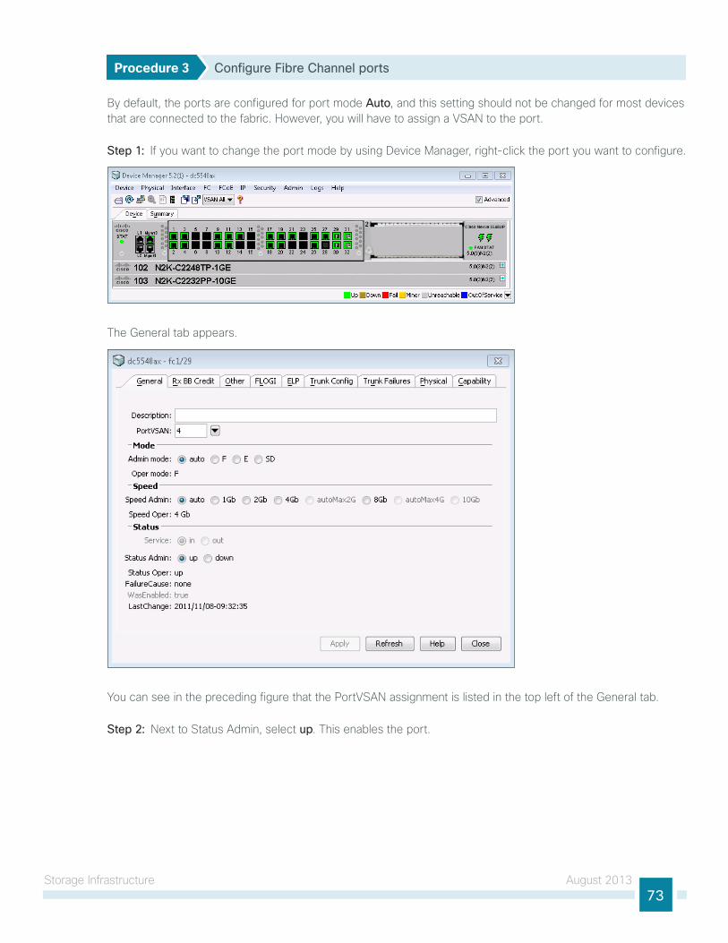
storage infrastructure August 201373
Procedure 3 Configure Fibre Channel ports
By default, the ports are configured for port mode Auto, and this setting should not be changed for most devices that are connected to the fabric. however, you will have to assign a VsAn to the port.
Step 1: if you want to change the port mode by using Device Manager, right-click the port you want to configure.
the general tab appears.
you can see in the preceding figure that the PortVsAn assignment is listed in the top left of the general tab.
Step 2: next to status Admin, select up. this enables the port.
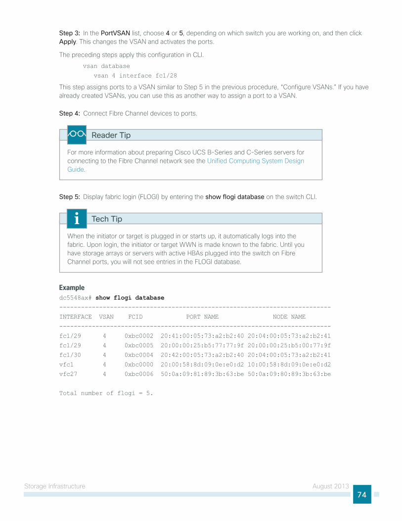
storage infrastructure August 201374
Step 3: in the PortVSAN list, choose 4 or 5, depending on which switch you are working on, and then click Apply. this changes the VsAn and activates the ports.
the preceding steps apply this configuration in Cli.
vsan database
vsan 4 interface fc1/28
this step assigns ports to a VsAn similar to step 5 in the previous procedure, “Configure VsAns.” if you have already created VsAns, you can use this as another way to assign a port to a VsAn.
Step 4: Connect Fibre Channel devices to ports.
For more information about preparing Cisco uCs B-series and C-series servers for connecting to the Fibre Channel network see the unified Computing system Design guide.
Reader Tip
Step 5: Display fabric login (Flogi) by entering the show flogi database on the switch Cli.
When the initiator or target is plugged in or starts up, it automatically logs into the fabric. upon login, the initiator or target WWn is made known to the fabric. until you have storage arrays or servers with active hBAs plugged into the switch on Fibre Channel ports, you will not see entries in the Flogi database.
Tech Tip
Exampledc5548ax# show flogi database---------------------------------------------------------------------------
INTERFACE VSAN FCID PORT NAME NODE NAME
---------------------------------------------------------------------------
fc1/29 4 0xbc0002 20:41:00:05:73:a2:b2:40 20:04:00:05:73:a2:b2:41
fc1/29 4 0xbc0005 20:00:00:25:b5:77:77:9f 20:00:00:25:b5:00:77:9f
fc1/30 4 0xbc0004 20:42:00:05:73:a2:b2:40 20:04:00:05:73:a2:b2:41
vfc1 4 0xbc0000 20:00:58:8d:09:0e:e0:d2 10:00:58:8d:09:0e:e0:d2
vfc27 4 0xbc0006 50:0a:09:81:89:3b:63:be 50:0a:09:80:89:3b:63:be
Total number of flogi = 5.
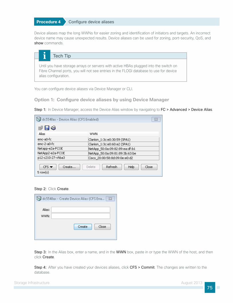
storage infrastructure August 201375
Procedure 4 Configure device aliases
Device aliases map the long WWns for easier zoning and identification of initiators and targets. An incorrect device name may cause unexpected results. Device aliases can be used for zoning, port-security, Qos, and show commands.
until you have storage arrays or servers with active hBAs plugged into the switch on Fibre Channel ports, you will not see entries in the Flogi database to use for device alias configuration.
Tech Tip
you can configure device aliases via Device Manager or Cli.
Option 1: Configure device aliases by using Device Manager
Step 1: in Device Manager, access the Device Alias window by navigating to FC > Advanced > Device Alias.
Step 2: Click Create.
Step 3: in the Alias box, enter a name, and in the WWN box, paste in or type the WWn of the host, and then click Create.
Step 4: After you have created your devices aliases, click CFS > Commit. the changes are written to the database.
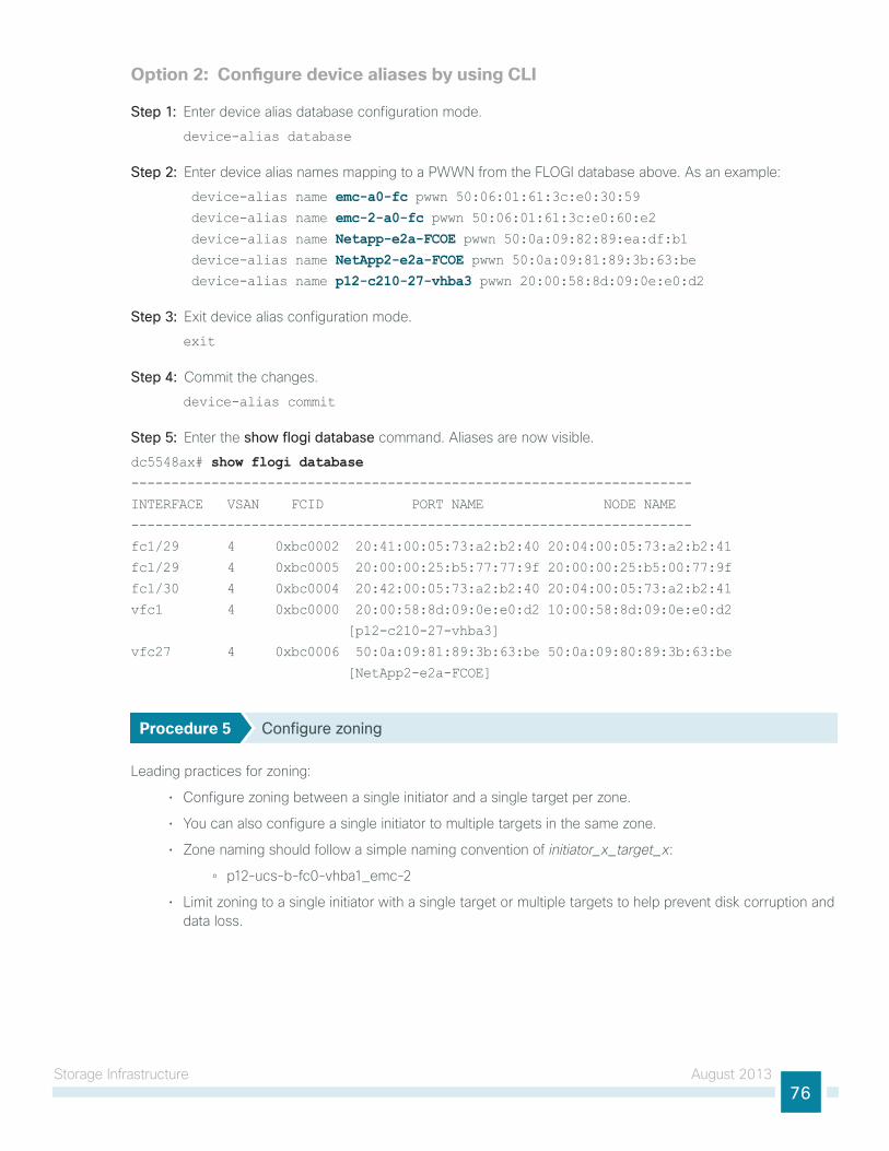
storage infrastructure August 201376
Option 2: Configure device aliases by using CLI
Step 1: enter device alias database configuration mode.
device-alias database
Step 2: enter device alias names mapping to a PWWn from the Flogi database above. As an example:
device-alias name emc-a0-fc pwwn 50:06:01:61:3c:e0:30:59 device-alias name emc-2-a0-fc pwwn 50:06:01:61:3c:e0:60:e2 device-alias name Netapp-e2a-FCOE pwwn 50:0a:09:82:89:ea:df:b1 device-alias name NetApp2-e2a-FCOE pwwn 50:0a:09:81:89:3b:63:be device-alias name p12-c210-27-vhba3 pwwn 20:00:58:8d:09:0e:e0:d2
Step 3: exit device alias configuration mode.
exit
Step 4: Commit the changes.
device-alias commit
Step 5: enter the show flogi database command. Aliases are now visible.
dc5548ax# show flogi database----------------------------------------------------------------------
INTERFACE VSAN FCID PORT NAME NODE NAME
----------------------------------------------------------------------
fc1/29 4 0xbc0002 20:41:00:05:73:a2:b2:40 20:04:00:05:73:a2:b2:41
fc1/29 4 0xbc0005 20:00:00:25:b5:77:77:9f 20:00:00:25:b5:00:77:9f
fc1/30 4 0xbc0004 20:42:00:05:73:a2:b2:40 20:04:00:05:73:a2:b2:41
vfc1 4 0xbc0000 20:00:58:8d:09:0e:e0:d2 10:00:58:8d:09:0e:e0:d2
[p12-c210-27-vhba3]
vfc27 4 0xbc0006 50:0a:09:81:89:3b:63:be 50:0a:09:80:89:3b:63:be
[NetApp2-e2a-FCOE]
Procedure 5 Configure zoning
leading practices for zoning:
• Configure zoning between a single initiator and a single target per zone.
• you can also configure a single initiator to multiple targets in the same zone.
• Zone naming should follow a simple naming convention of initiator_x_target_x:
◦ p12-ucs-b-fc0-vhba1_emc-2
• limit zoning to a single initiator with a single target or multiple targets to help prevent disk corruption and data loss.
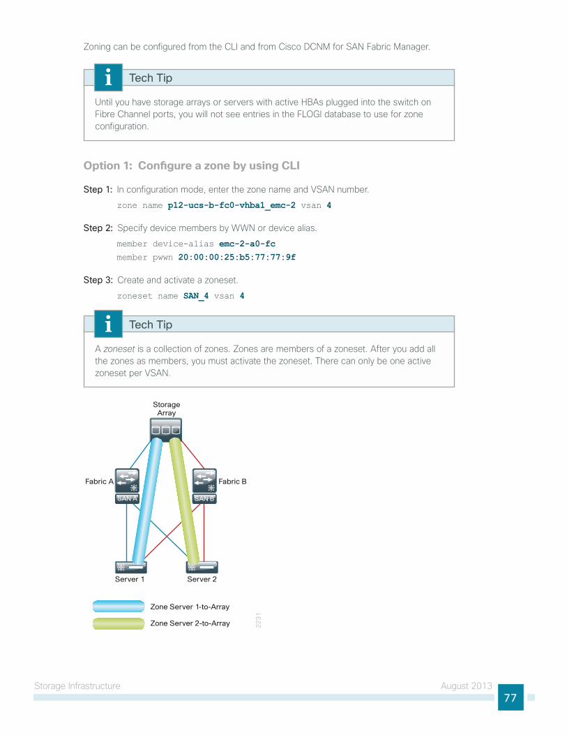
storage infrastructure August 201377
Zoning can be configured from the Cli and from Cisco DCnM for sAn Fabric Manager.
until you have storage arrays or servers with active hBAs plugged into the switch on Fibre Channel ports, you will not see entries in the Flogi database to use for zone configuration.
Tech Tip
Option 1: Configure a zone by using CLI
Step 1: in configuration mode, enter the zone name and VsAn number.
zone name p12-ucs-b-fc0-vhba1_emc-2 vsan 4
Step 2: specify device members by WWn or device alias.
member device-alias emc-2-a0-fcmember pwwn 20:00:00:25:b5:77:77:9f
Step 3: Create and activate a zoneset.
zoneset name SAN_4 vsan 4
A zoneset is a collection of zones. Zones are members of a zoneset. After you add all the zones as members, you must activate the zoneset. there can only be one active zoneset per VsAn.
Tech Tip
22
31
Zone Server 1-to-Array
Zone Server 2-to-Array
StorageArray
Fabric A Fabric B
Server 1 Server 2
SAN BSAN A
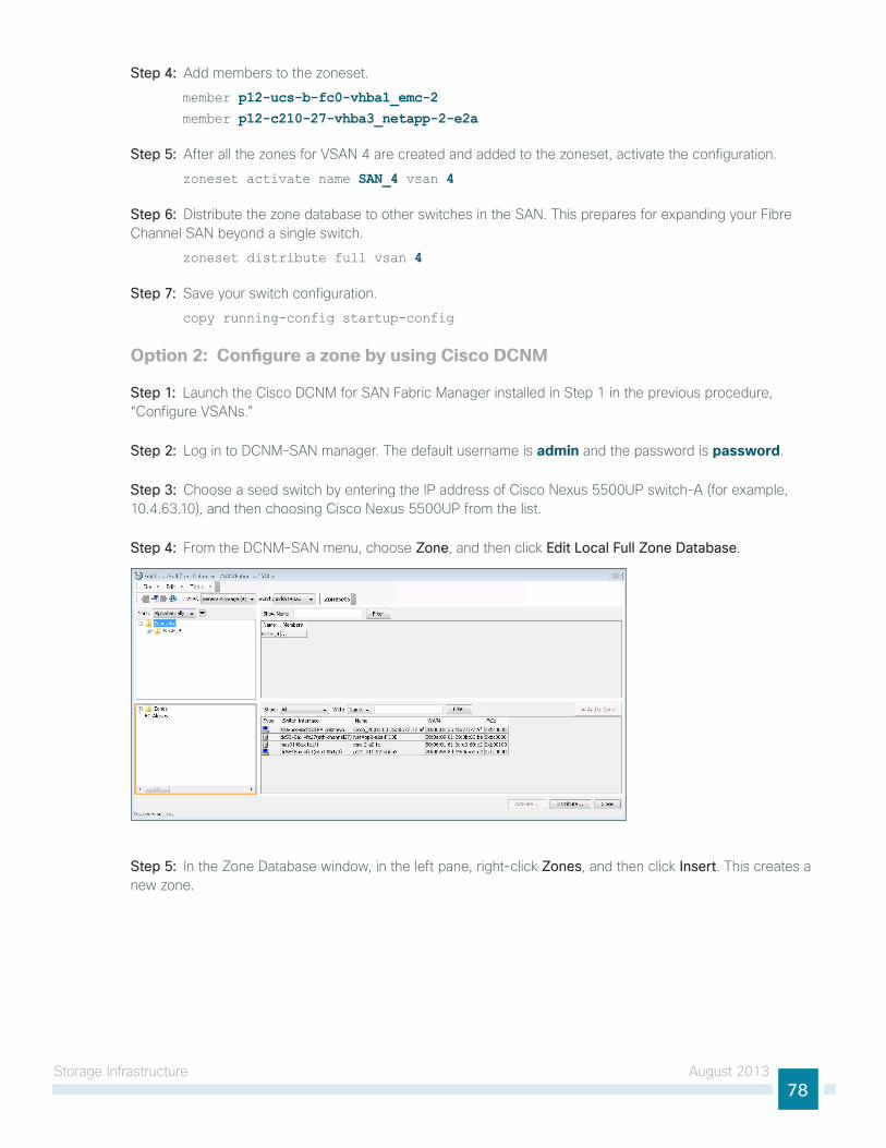
storage infrastructure August 201378
Step 4: Add members to the zoneset.
member p12-ucs-b-fc0-vhba1_emc-2member p12-c210-27-vhba3_netapp-2-e2a
Step 5: After all the zones for VsAn 4 are created and added to the zoneset, activate the configuration.
zoneset activate name SAN_4 vsan 4
Step 6: Distribute the zone database to other switches in the sAn. this prepares for expanding your Fibre Channel sAn beyond a single switch.
zoneset distribute full vsan 4
Step 7: save your switch configuration.
copy running-config startup-config
Option 2: Configure a zone by using Cisco DCNM
Step 1: launch the Cisco DCnM for sAn Fabric Manager installed in step 1 in the previous procedure, “Configure VsAns.”
Step 2: log in to DCnM-sAn manager. the default username is admin and the password is password.
Step 3: Choose a seed switch by entering the iP address of Cisco nexus 5500uP switch-A (for example, 10.4.63.10), and then choosing Cisco nexus 5500uP from the list.
Step 4: From the DCnM-sAn menu, choose Zone, and then click Edit Local Full Zone Database.
Step 5: in the Zone Database window, in the left pane, right-click Zones, and then click Insert. this creates a new zone.
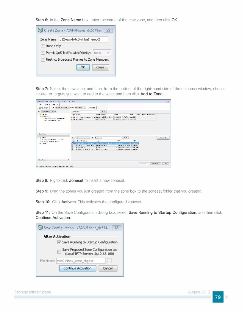
storage infrastructure August 201379
Step 6: in the Zone Name box, enter the name of the new zone, and then click OK.
Step 7: select the new zone, and then, from the bottom of the right-hand side of the database window, choose initiator or targets you want to add to the zone, and then click Add to Zone.
Step 8: Right-click Zoneset to insert a new zoneset.
Step 9: Drag the zones you just created from the zone box to the zoneset folder that you created.
Step 10: Click Activate. this activates the configured zoneset
Step 11: on the save Configuration dialog box, select Save Running to Startup Configuration, and then click Continue Activation.
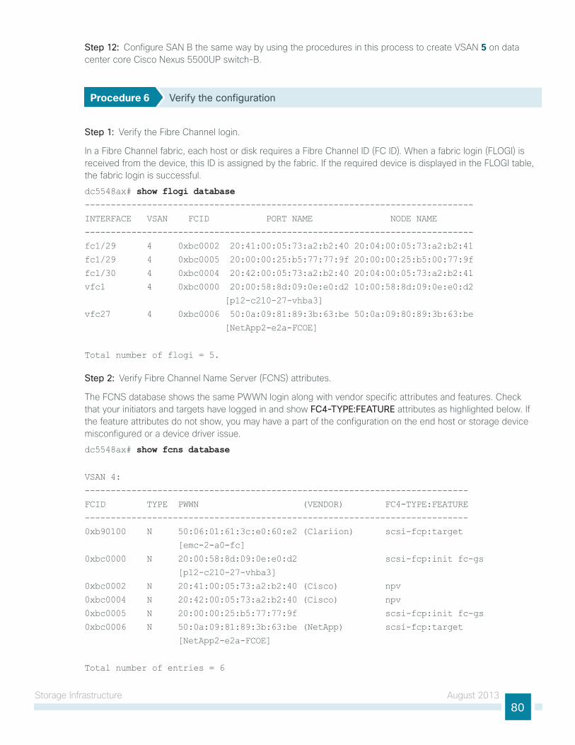
storage infrastructure August 201380
Step 12: Configure sAn B the same way by using the procedures in this process to create VsAn 5 on data center core Cisco nexus 5500uP switch-B.
Procedure 6 Verify the configuration
Step 1: Verify the Fibre Channel login.
in a Fibre Channel fabric, each host or disk requires a Fibre Channel iD (FC iD). When a fabric login (Flogi) is received from the device, this iD is assigned by the fabric. if the required device is displayed in the Flogi table, the fabric login is successful.
dc5548ax# show flogi database---------------------------------------------------------------------------
INTERFACE VSAN FCID PORT NAME NODE NAME
---------------------------------------------------------------------------
fc1/29 4 0xbc0002 20:41:00:05:73:a2:b2:40 20:04:00:05:73:a2:b2:41
fc1/29 4 0xbc0005 20:00:00:25:b5:77:77:9f 20:00:00:25:b5:00:77:9f
fc1/30 4 0xbc0004 20:42:00:05:73:a2:b2:40 20:04:00:05:73:a2:b2:41
vfc1 4 0xbc0000 20:00:58:8d:09:0e:e0:d2 10:00:58:8d:09:0e:e0:d2
[p12-c210-27-vhba3]
vfc27 4 0xbc0006 50:0a:09:81:89:3b:63:be 50:0a:09:80:89:3b:63:be
[NetApp2-e2a-FCOE]
Total number of flogi = 5.
Step 2: Verify Fibre Channel name server (FCns) attributes.
the FCns database shows the same PWWn login along with vendor specific attributes and features. Check that your initiators and targets have logged in and show FC4-TYPE:FEATURE attributes as highlighted below. if the feature attributes do not show, you may have a part of the configuration on the end host or storage device misconfigured or a device driver issue.
dc5548ax# show fcns database
VSAN 4:
--------------------------------------------------------------------------
FCID TYPE PWWN (VENDOR) FC4-TYPE:FEATURE
--------------------------------------------------------------------------
0xb90100 N 50:06:01:61:3c:e0:60:e2 (Clariion) scsi-fcp:target
[emc-2-a0-fc]
0xbc0000 N 20:00:58:8d:09:0e:e0:d2 scsi-fcp:init fc-gs
[p12-c210-27-vhba3]
0xbc0002 N 20:41:00:05:73:a2:b2:40 (Cisco) npv
0xbc0004 N 20:42:00:05:73:a2:b2:40 (Cisco) npv
0xbc0005 N 20:00:00:25:b5:77:77:9f scsi-fcp:init fc-gs
0xbc0006 N 50:0a:09:81:89:3b:63:be (NetApp) scsi-fcp:target
[NetApp2-e2a-FCOE]
Total number of entries = 6
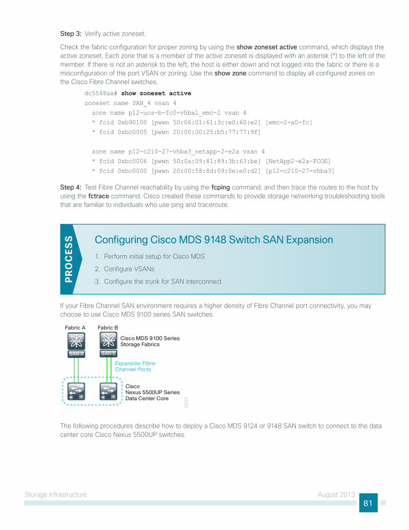
storage infrastructure August 201381
Step 3: Verify active zoneset.
Check the fabric configuration for proper zoning by using the show zoneset active command, which displays the active zoneset. each zone that is a member of the active zoneset is displayed with an asterisk (*) to the left of the member. if there is not an asterisk to the left, the host is either down and not logged into the fabric or there is a misconfiguration of the port VsAn or zoning. use the show zone command to display all configured zones on the Cisco Fibre Channel switches.
dc5548ax# show zoneset activezoneset name SAN_4 vsan 4
zone name p12-ucs-b-fc0-vhba1_emc-2 vsan 4
* fcid 0xb90100 [pwwn 50:06:01:61:3c:e0:60:e2] [emc-2-a0-fc]
* fcid 0xbc0005 [pwwn 20:00:00:25:b5:77:77:9f]
zone name p12-c210-27-vhba3_netapp-2-e2a vsan 4
* fcid 0xbc0006 [pwwn 50:0a:09:81:89:3b:63:be] [NetApp2-e2a-FCOE]
* fcid 0xbc0000 [pwwn 20:00:58:8d:09:0e:e0:d2] [p12-c210-27-vhba3]
Step 4: test Fibre Channel reachability by using the fcping command, and then trace the routes to the host by using the fctrace command. Cisco created these commands to provide storage networking troubleshooting tools that are familiar to individuals who use ping and traceroute.
Configuring Cisco MDS 9148 Switch SAN Expansion
1. Perform initial setup for Cisco MDs
2. Configure VsAns
3. Configure the trunk for sAn interconnectPR
OC
ESS
if your Fibre Channel sAn environment requires a higher density of Fibre Channel port connectivity, you may choose to use Cisco MDs 9100 series sAn switches.
22
32
SAN A
Fabric A
Cisco MDS 9100 SeriesStorage Fabrics
Cisco Nexus 5500UP SeriesData Center Core
Fabric B
Expansion FibreChannel Ports
SAN A SAN B
the following procedures describe how to deploy a Cisco MDs 9124 or 9148 sAn switch to connect to the data center core Cisco nexus 5500uP switches.
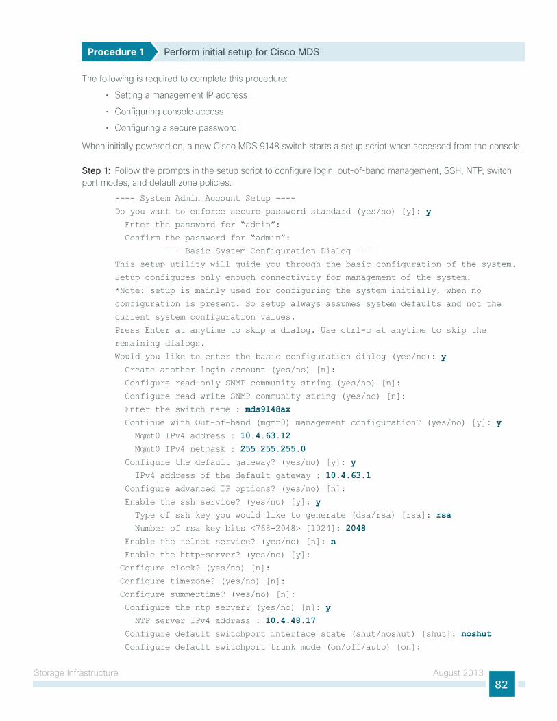
storage infrastructure August 201382
Procedure 1 Perform initial setup for Cisco MDS
the following is required to complete this procedure:
• setting a management iP address
• Configuring console access
• Configuring a secure password
When initially powered on, a new Cisco MDs 9148 switch starts a setup script when accessed from the console.
Step 1: Follow the prompts in the setup script to configure login, out-of-band management, ssh, ntP, switch port modes, and default zone policies.
---- System Admin Account Setup ----
Do you want to enforce secure password standard (yes/no) [y]: y Enter the password for “admin”:
Confirm the password for “admin”:
---- Basic System Configuration Dialog ----
This setup utility will guide you through the basic configuration of the system.
Setup configures only enough connectivity for management of the system.
*Note: setup is mainly used for configuring the system initially, when no
configuration is present. So setup always assumes system defaults and not the
current system configuration values.
Press Enter at anytime to skip a dialog. Use ctrl-c at anytime to skip the
remaining dialogs.
Would you like to enter the basic configuration dialog (yes/no): y Create another login account (yes/no) [n]:
Configure read-only SNMP community string (yes/no) [n]:
Configure read-write SNMP community string (yes/no) [n]:
Enter the switch name : mds9148ax Continue with Out-of-band (mgmt0) management configuration? (yes/no) [y]: y Mgmt0 IPv4 address : 10.4.63.12 Mgmt0 IPv4 netmask : 255.255.255.0 Configure the default gateway? (yes/no) [y]: y IPv4 address of the default gateway : 10.4.63.1 Configure advanced IP options? (yes/no) [n]:
Enable the ssh service? (yes/no) [y]: y Type of ssh key you would like to generate (dsa/rsa) [rsa]: rsa Number of rsa key bits <768-2048> [1024]: 2048 Enable the telnet service? (yes/no) [n]: n Enable the http-server? (yes/no) [y]:
Configure clock? (yes/no) [n]:
Configure timezone? (yes/no) [n]:
Configure summertime? (yes/no) [n]:
Configure the ntp server? (yes/no) [n]: y NTP server IPv4 address : 10.4.48.17 Configure default switchport interface state (shut/noshut) [shut]: noshut Configure default switchport trunk mode (on/off/auto) [on]:
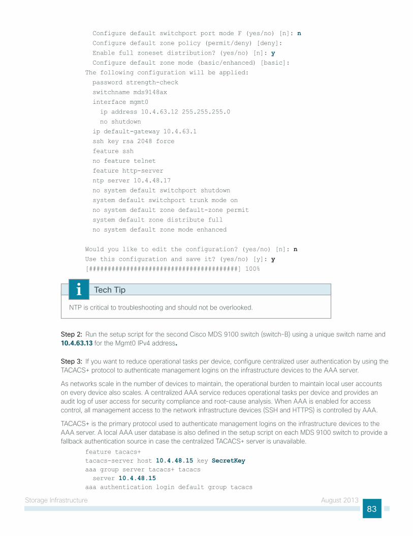
storage infrastructure August 201383
Configure default switchport port mode F (yes/no) [n]: n Configure default zone policy (permit/deny) [deny]:
Enable full zoneset distribution? (yes/no) [n]: y Configure default zone mode (basic/enhanced) [basic]:
The following configuration will be applied:
password strength-check
switchname mds9148ax
interface mgmt0
ip address 10.4.63.12 255.255.255.0
no shutdown
ip default-gateway 10.4.63.1
ssh key rsa 2048 force
feature ssh
no feature telnet
feature http-server
ntp server 10.4.48.17
no system default switchport shutdown
system default switchport trunk mode on
no system default zone default-zone permit
system default zone distribute full
no system default zone mode enhanced
Would you like to edit the configuration? (yes/no) [n]: nUse this configuration and save it? (yes/no) [y]: y[########################################] 100%
ntP is critical to troubleshooting and should not be overlooked.
Tech Tip
Step 2: Run the setup script for the second Cisco MDs 9100 switch (switch-B) using a unique switch name and 10.4.63.13 for the Mgmt0 iPv4 address.
Step 3: if you want to reduce operational tasks per device, configure centralized user authentication by using the tACACs+ protocol to authenticate management logins on the infrastructure devices to the AAA server.
As networks scale in the number of devices to maintain, the operational burden to maintain local user accounts on every device also scales. A centralized AAA service reduces operational tasks per device and provides an audit log of user access for security compliance and root-cause analysis. When AAA is enabled for access control, all management access to the network infrastructure devices (ssh and httPs) is controlled by AAA.
tACACs+ is the primary protocol used to authenticate management logins on the infrastructure devices to the AAA server. A local AAA user database is also defined in the setup script on each MDs 9100 switch to provide a fallback authentication source in case the centralized tACACs+ server is unavailable.
feature tacacs+tacacs-server host 10.4.48.15 key SecretKeyaaa group server tacacs+ tacacs server 10.4.48.15aaa authentication login default group tacacs
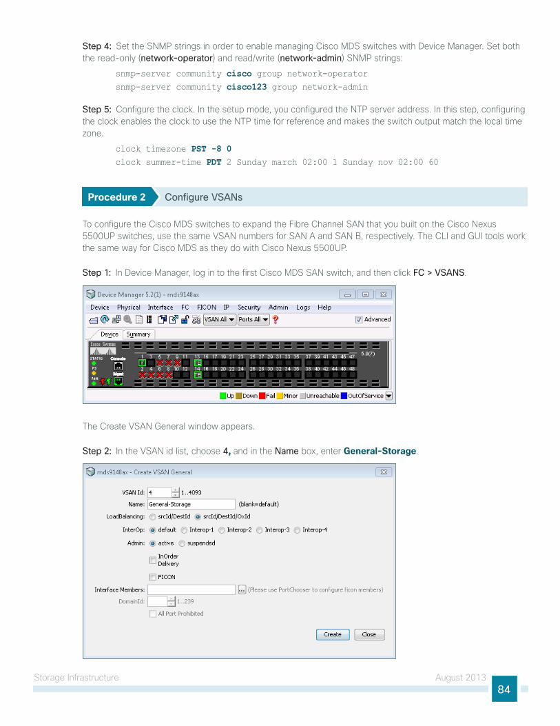
storage infrastructure August 201384
Step 4: set the snMP strings in order to enable managing Cisco MDs switches with Device Manager. set both the read-only (network-operator) and read/write (network-admin) snMP strings:
snmp-server community cisco group network-operatorsnmp-server community cisco123 group network-admin
Step 5: Configure the clock. in the setup mode, you configured the ntP server address. in this step, configuring the clock enables the clock to use the ntP time for reference and makes the switch output match the local time zone.
clock timezone PST -8 0clock summer-time PDT 2 Sunday march 02:00 1 Sunday nov 02:00 60
Procedure 2 Configure VSANs
to configure the Cisco MDs switches to expand the Fibre Channel sAn that you built on the Cisco nexus 5500uP switches, use the same VsAn numbers for sAn A and sAn B, respectively. the Cli and gui tools work the same way for Cisco MDs as they do with Cisco nexus 5500uP.
Step 1: in Device Manager, log in to the first Cisco MDs sAn switch, and then click FC > VSANS.
the Create VsAn general window appears.
Step 2: in the VsAn id list, choose 4, and in the Name box, enter General-Storage.
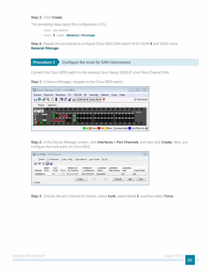
storage infrastructure August 201385
Step 3: Click Create.
the preceding steps apply this configuration in Cli.
vsan database
vsan 4 name General-Storage
Step 4: Repeat this procedure to configure Cisco MDs sAn switch-B for VsAn 5 and VsAn name General-Storage.
Procedure 3 Configure the trunk for SAN interconnect
Connect the Cisco MDs switch to the existing Cisco nexus 5500uP core Fibre Channel sAn.
Step 1: in Device Manager, navigate to the Cisco MDs switch.
Step 2: in the Device Manager screen, click Interfaces > Port Channels, and then click Create. next, you configure the trunk ports on Cisco MDs.
Step 3: Choose the port channel id number, select trunk, select Mode E, and then select Force.
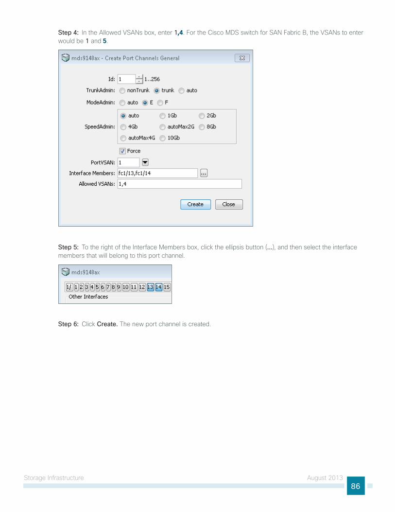
storage infrastructure August 201386
Step 4: in the Allowed VsAns box, enter 1,4. For the Cisco MDs switch for sAn Fabric B, the VsAns to enter would be 1 and 5.
Step 5: to the right of the interface Members box, click the ellipsis button (…), and then select the interface members that will belong to this port channel.
Step 6: Click Create. the new port channel is created.
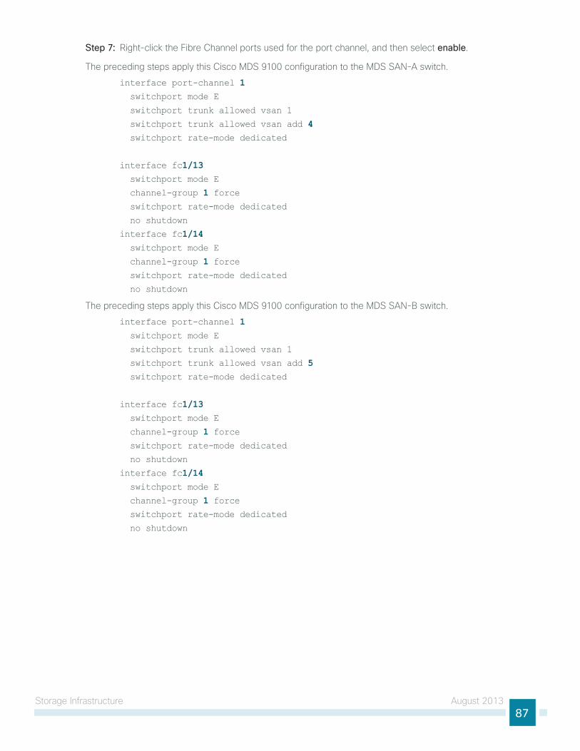
storage infrastructure August 201387
Step 7: Right-click the Fibre Channel ports used for the port channel, and then select enable.
the preceding steps apply this Cisco MDs 9100 configuration to the MDs sAn-A switch.
interface port-channel 1 switchport mode E
switchport trunk allowed vsan 1
switchport trunk allowed vsan add 4 switchport rate-mode dedicated
interface fc1/13 switchport mode E
channel-group 1 force switchport rate-mode dedicated
no shutdown
interface fc1/14 switchport mode E
channel-group 1 force switchport rate-mode dedicated
no shutdown
the preceding steps apply this Cisco MDs 9100 configuration to the MDs sAn-B switch.
interface port-channel 1 switchport mode E
switchport trunk allowed vsan 1
switchport trunk allowed vsan add 5 switchport rate-mode dedicated
interface fc1/13 switchport mode E
channel-group 1 force switchport rate-mode dedicated
no shutdown
interface fc1/14 switchport mode E
channel-group 1 force switchport rate-mode dedicated
no shutdown
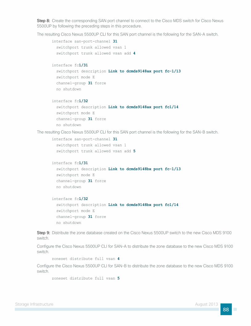
storage infrastructure August 201388
Step 8: Create the corresponding sAn port channel to connect to the Cisco MDs switch for Cisco nexus 5500uP by following the preceding steps in this procedure.
the resulting Cisco nexus 5500uP Cli for this sAn port channel is the following for the sAn-A switch.
interface san-port-channel 31 switchport trunk allowed vsan 1
switchport trunk allowed vsan add 4
interface fc1/31 switchport description Link to dcmds9148ax port fc-1/13 switchport mode E
channel-group 31 force no shutdown
interface fc1/32 switchport description Link to dcmds9148ax port fc1/14 switchport mode E
channel-group 31 force no shutdown
the resulting Cisco nexus 5500uP Cli for this sAn port channel is the following for the sAn-B switch.
interface san-port-channel 31 switchport trunk allowed vsan 1
switchport trunk allowed vsan add 5
interface fc1/31 switchport description Link to dcmds9148bx port fc-1/13 switchport mode E
channel-group 31 force no shutdown
interface fc1/32 switchport description Link to dcmds9148bx port fc1/14 switchport mode E
channel-group 31 force no shutdown
Step 9: Distribute the zone database created on the Cisco nexus 5500uP switch to the new Cisco MDs 9100 switch.
Configure the Cisco nexus 5500uP Cli for sAn-A to distribute the zone database to the new Cisco MDs 9100 switch.
zoneset distribute full vsan 4
Configure the Cisco nexus 5500uP Cli for sAn-B to distribute the zone database to the new Cisco MDs 9100 switch.
zoneset distribute full vsan 5
storage infrastructure August 201389
Configuring FCoE Host Connectivity
1. Configure FCoe Qos
2. Configure host-facing FCoe ports
3. Verify FCoe connectivityPR
OC
ESS
Cisco uCs C-series rack-mount servers ship with onboard 10/100/1000 ethernet adapters and Cisco integrated Management Controller (CiMC), which uses a 10/100 or 10/100/1000 ethernet port. to get the most out of the rack servers and minimize cabling in the unified Computing architecture, the Cisco uCs C-series rack-mount server is connected to a unified fabric. the Cisco nexus 5500uP series switch that connects the Cisco uCs 5100 series Blade server Chassis to the network can also be used to extend Fibre Channel traffic over 10-gigabit ethernet. the Cisco nexus 5500uP series switch consolidates i/o onto one set of 10-gigabit ethernet cables, eliminating redundant adapters, cables, and ports. A single converged network adapter (CnA) card and set of cables connects servers to the ethernet and Fibre Channel networks by using FCoe. FCoe and CnA also allows the use of a single cabling infrastructure within server racks.
in the data center design, the Cisco uCs C-series rack-mount server is configured with a dual-port CnA. Cabling the Cisco uCs C-series server with a CnA limits the cables to three: one for each port on the CnA and one for the CiMC connection.
A server connecting to Cisco nexus 5500uP that is running FCoe consumes a Fibre Channel port license. if you are connecting the FCoe attached servers to a Cisco FeX model 2232PP, only the 5500uP ports connected to the Cisco FeX require a Fibre Channel port license for each port connecting to the Cisco FeX. this way, you could connect up to 32 FCoe servers to a Cisco FeX 2232PP and only use Fibre Channel port licenses for the Cisco FeX uplinks.
Tech Tip
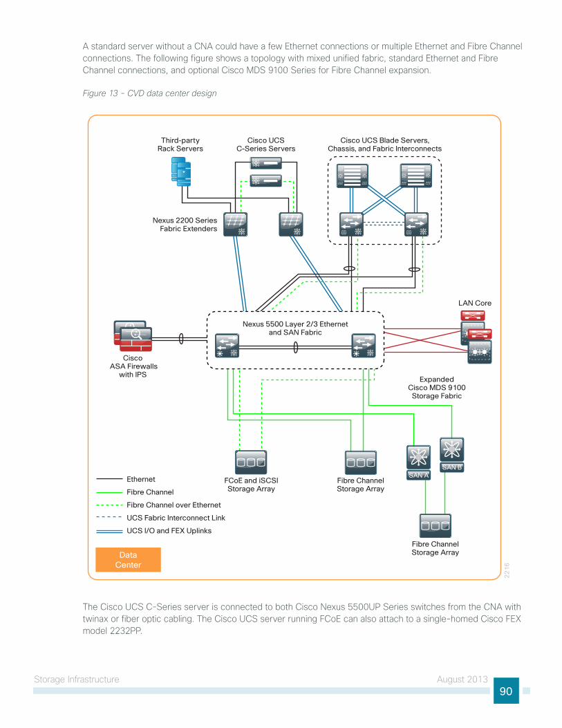
storage infrastructure August 201390
A standard server without a CnA could have a few ethernet connections or multiple ethernet and Fibre Channel connections. the following figure shows a topology with mixed unified fabric, standard ethernet and Fibre Channel connections, and optional Cisco MDs 9100 series for Fibre Channel expansion.
Figure 13 - CVD data center design
22
16
Cisco ASA Firewalls
with IPS
Cisco UCSC-Series Servers
Cisco UCS Blade Servers, Chassis, and Fabric Interconnects
LAN Core
FCoE and iSCSIStorage Array
ExpandedCisco MDS 9100
Storage Fabric
Nexus 2200 SeriesFabric Extenders
Fibre ChannelStorage Array
Fibre ChannelStorage Array
SAN ASAN B
Nexus 5500 Layer 2/3 Ethernetand SAN Fabric
Third-partyRack Servers
SAN BSAN AEthernet
Fibre Channel
Fibre Channel over Ethernet
UCS Fabric Interconnect Link
UCS I/O and FEX Uplinks
DataCenter
the Cisco uCs C-series server is connected to both Cisco nexus 5500uP series switches from the CnA with twinax or fiber optic cabling. the Cisco uCs server running FCoe can also attach to a single-homed Cisco FeX model 2232PP.
storage infrastructure August 201391
At this time, FCoe-connected hosts can only connect over 10-gigabit ethernet and must use a fiber optic or twinax connection.
Tech Tip
the recommended approach is to connect the CiMC management port(s) to an ethernet port on the out-of-band management switch. Alternatively, you can connect the CiMC management port(s) to a Cisco nexus 2248 fabric extender port in the management VlAn (163).
Cisco Nexus 5500UP Configuration for FCoEin previous processes, you enabled Cisco nexus 5500uP series FCoe functionality. in this process, you perform the following tasks to allow a Cisco C-series server to connect using FCoe:
• Create a virtual Fibre Channel interface
• Assign the VsAn to a virtual Fibre Channel interface
• Configure the ethernet port and trunking
Procedure 1 Configure FCoE QoS
Configuration is the same across both of the Cisco nexus 5500uP series switches with the exception of the VsAn configured for sAn fabric A and for sAn fabric B.
the Cisco nexus 5500uP does not preconfigure Qos for FCoe traffic.
Step 1: ensure that the Cisco nexus 5500uP data center core switches have been programmed with a Qos policy to support lossless FCoe transport. the Qos policy for the data center core nexus 5500uP switches was defined in Procedure 3 “Configure Qos policies.”
you must have a Qos policy on the Cisco nexus 5500uP switches that classifies FCoe for lossless operation.
Tech Tip
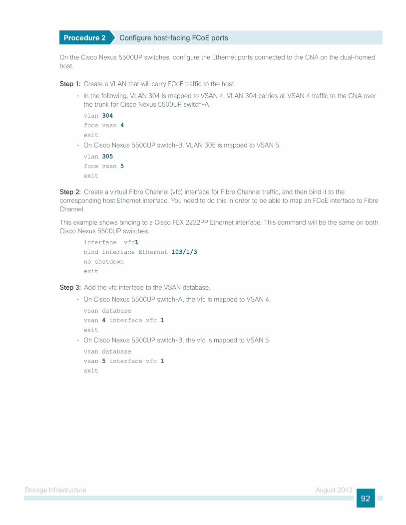
storage infrastructure August 201392
Procedure 2 Configure host-facing FCoE ports
on the Cisco nexus 5500uP switches, configure the ethernet ports connected to the CnA on the dual-homed host.
Step 1: Create a VlAn that will carry FCoe traffic to the host.
• in the following, VlAn 304 is mapped to VsAn 4. VlAn 304 carries all VsAn 4 traffic to the CnA over the trunk for Cisco nexus 5500uP switch-A.
vlan 304fcoe vsan 4exit
• on Cisco nexus 5500uP switch-B, VlAn 305 is mapped to VsAn 5.
vlan 305fcoe vsan 5exit
Step 2: Create a virtual Fibre Channel (vfc) interface for Fibre Channel traffic, and then bind it to the corresponding host ethernet interface. you need to do this in order to be able to map an FCoe interface to Fibre Channel.
this example shows binding to a Cisco FeX 2232PP ethernet interface. this command will be the same on both Cisco nexus 5500uP switches.
interface vfc1bind interface Ethernet 103/1/3no shutdown
exit
Step 3: Add the vfc interface to the VsAn database.
• on Cisco nexus 5500uP switch-A, the vfc is mapped to VsAn 4.
vsan database
vsan 4 interface vfc 1exit
• on Cisco nexus 5500uP switch-B, the vfc is mapped to VsAn 5.
vsan database
vsan 5 interface vfc 1exit
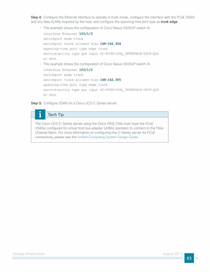
storage infrastructure August 201393
Step 4: Configure the ethernet interface to operate in trunk mode, configure the interface with the FCoe VsAn and any data VlAns required by the host, and configure the spanning-tree port type as trunk edge.
• this example shows the configuration of Cisco nexus 5500uP switch-A.
interface Ethernet 103/1/3switchport mode trunk
switchport trunk allowed vlan 148-162,304spanning-tree port type edge trunk
service-policy type qos input DC-FCOE+1P4Q_INTERFACE-DSCP-QOS
no shut
• this example shows the configuration of Cisco nexus 5500uP switch-B.
interface Ethernet 103/1/3switchport mode trunk
switchport trunk allowed vlan 148-162,305spanning-tree port type edge trunk
service-policy type qos input DC-FCOE+1P4Q_INTERFACE-DSCP-QOS
no shut
Step 5: Configure VsAn on a Cisco uCs C-series server.
the Cisco uCs C-series server using the Cisco P81e CnA must have the FCoe VsAns configured for virtual host bus adapter (vhBA) operation to connect to the Fibre Channel fabric. For more information on configuring the C-series server for FCoe connectivity, please see the unified Computing system Design guide.
Tech Tip
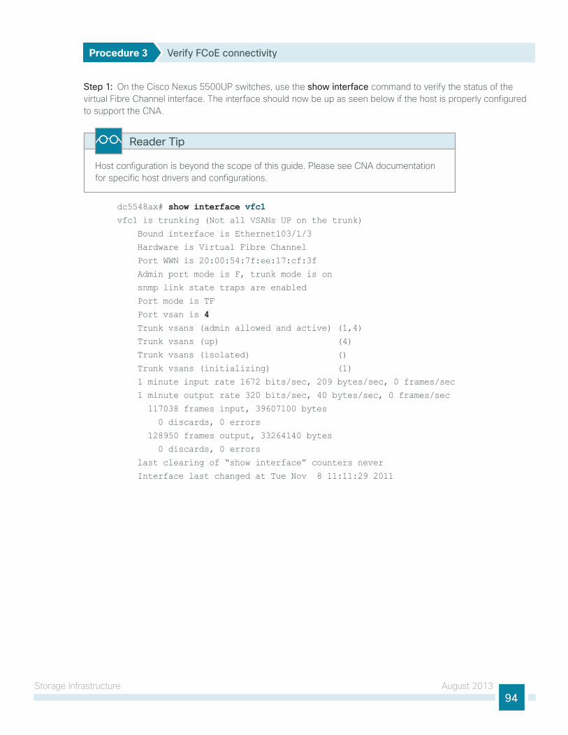
storage infrastructure August 201394
Procedure 3 Verify FCoE connectivity
Step 1: on the Cisco nexus 5500uP switches, use the show interface command to verify the status of the virtual Fibre Channel interface. the interface should now be up as seen below if the host is properly configured to support the CnA.
host configuration is beyond the scope of this guide. Please see CnA documentation for specific host drivers and configurations.
Reader Tip
dc5548ax# show interface vfc1vfc1 is trunking (Not all VSANs UP on the trunk)
Bound interface is Ethernet103/1/3
Hardware is Virtual Fibre Channel
Port WWN is 20:00:54:7f:ee:17:cf:3f
Admin port mode is F, trunk mode is on
snmp link state traps are enabled
Port mode is TF
Port vsan is 4 Trunk vsans (admin allowed and active) (1,4)
Trunk vsans (up) (4)
Trunk vsans (isolated) ()
Trunk vsans (initializing) (1)
1 minute input rate 1672 bits/sec, 209 bytes/sec, 0 frames/sec
1 minute output rate 320 bits/sec, 40 bytes/sec, 0 frames/sec
117038 frames input, 39607100 bytes
0 discards, 0 errors
128950 frames output, 33264140 bytes
0 discards, 0 errors
last clearing of “show interface” counters never
Interface last changed at Tue Nov 8 11:11:29 2011
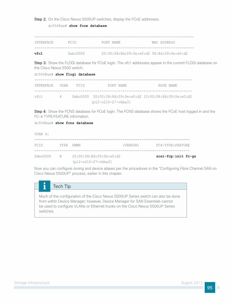
storage infrastructure August 201395
Step 2: on the Cisco nexus 5500uP switches, display the FCoe addresses.
dc5548ax# show fcoe database
----------------------------------------------------------------------------
INTERFACE FCID PORT NAME MAC ADDRESS
----------------------------------------------------------------------------
vfc1 0xbc0000 20:00:58:8d:09:0e:e0:d2 58:8d:09:0e:e0:d2
Step 3: show the Flogi database for FCoe login. the vfc1 addresses appear in the current Flogi database on the Cisco nexus 5500 switch.
dc5548ax# show flogi database---------------------------------------------------------------------------
INTERFACE VSAN FCID PORT NAME NODE NAME
---------------------------------------------------------------------------
vfc1 4 0xbc0000 20:00:58:8d:09:0e:e0:d2 10:00:58:8d:09:0e:e0:d2
[p12-c210-27-vhba3]
Step 4: show the FCns database for FCoe login. the FCns database shows the FCoe host logged in and the FC-4 tyPe:FeAtuRe information.
dc5548ax# show fcns database
VSAN 4:
--------------------------------------------------------------------------
FCID TYPE PWWN (VENDOR) FC4-TYPE:FEATURE
--------------------------------------------------------------------------
0xbc0000 N 20:00:58:8d:09:0e:e0:d2 scsi-fcp:init fc-gs [p12-c210-27-vhba3]
now you can configure zoning and device aliases per the procedures in the “Configuring Fibre Channel sAn on Cisco nexus 5500uP” process, earlier in this chapter.
Much of the configuration of the Cisco nexus 5500uP series switch can also be done from within Device Manager; however, Device Manager for sAn essentials cannot be used to configure VlAns or ethernet trunks on the Cisco nexus 5500uP series switches.
Tech Tip
Compute Connectivity August 201396
Compute Connectivity
Design Overviewserver virtualization offers the capability to run multiple application servers on a common hardware platform, allowing an organization to focus on maximizing the application capability of the data center while minimizing costs. increased capability and reduced costs are realized through multiple aspects:
• Multiple applications can be combined in a single hardware chassis, reducing the number of boxes that must be accommodated in data-center space
• simplified cable management, due to fewer required cable runs and greater flexibility in allocating network connectivity to hosts on an as-needed basis
• improved resiliency and application portability as hypervisors allow workload resiliency and load-sharing across multiple platforms, even in geographically dispersed locations
• Applications that are deployed on standardized hardware platforms, which reduces platform-management consoles and minimizes hardware spare stock challenges
• Minimized box count reduces power and cooling requirements, because there are fewer lightly loaded boxes idling away expensive wattage
the ability to virtualize server platforms to handle multiple operating systems and applications with hypervisor technologies building virtual machines allows the organization to lower capital and operating costs by collapsing more applications onto fewer physical servers. the hypervisor technology also provides the ability to cluster many virtual machines into a domain where workloads can be orchestrated to move around the data center to provide resiliency and load balancing, and to allow new applications to be deployed in hours versus days or weeks.
the ability to move virtual machines or application loads from one server to the next, whether the server is a blade server in a chassis-based system or a standalone rack-mount server, requires the network to be flexible and scalable, allowing any VlAn to appear anywhere in the data center. Cisco Virtual Port Channel (vPC) and Fabric extender (FeX) technologies are used extensively in this data center design to provide flexible ethernet connectivity to VlAns distributed across the data center in a scalable and resilient manner.
streamlining the management of server hardware and its interaction with networking and storage equipment is another important component of using this investment in an efficient manner. Cisco offers a simplified reference model for managing a small server room as it grows into a full-fledged data center. this model benefits from the ease of use offered by Cisco uCs. Cisco uCs provides a single graphical management tool for the provisioning and management of servers, network interfaces, storage interfaces, and the network components directly attached to them. Cisco uCs treats all of these components as a cohesive system, which simplifies these complex interactions and allows an organization to deploy the same efficient technologies as larger enterprises do, without a dramatic learning curve.
the primary computing platforms targeted for the CVD unified Computing reference architecture are Cisco uCs B-series Blade servers and Cisco uCs C-series Rack-Mount servers. the Cisco uCs Manager graphical interface provides ease of use that is consistent with the goals of CVD. When deployed in conjunction with the CVD data center network foundation, the environment provides the flexibility to support the concurrent use of the Cisco uCs B-series Blade servers, Cisco uCs C-series Rack-Mount servers, and third-party servers connected to 1- and 10-gigabit ethernet connections.
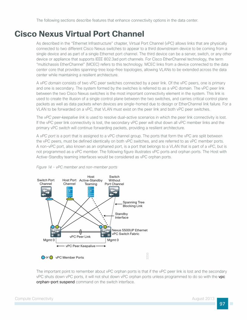
Compute Connectivity August 201397
the following sections describe features that enhance connectivity options in the data center.
Cisco Nexus Virtual Port ChannelAs described in the “ethernet infrastructure” chapter, Virtual Port Channel (vPC) allows links that are physically connected to two different Cisco nexus switches to appear to a third downstream device to be coming from a single device and as part of a single ethernet port channel. the third device can be a server, switch, or any other device or appliance that supports ieee 802.3ad port channels. For Cisco etherChannel technology, the term “multichassis etherChannel” (MCeC) refers to this technology. MCeC links from a device connected to the data center core that provides spanning-tree loop–free topologies, allowing VlAns to be extended across the data center while maintaining a resilient architecture.
A vPC domain consists of two vPC peer switches connected by a peer link. of the vPC peers, one is primary and one is secondary. the system formed by the switches is referred to as a vPC domain. the vPC peer link between the two Cisco nexus switches is the most important connectivity element in the system. this link is used to create the illusion of a single control plane between the two switches, and carries critical control plane packets as well as data packets when devices are single-homed due to design or etherChannel link failure. For a VlAn to be forwarded on a vPC, that VlAn must exist on the peer link and both vPC peer switches.
the vPC peer-keepalive link is used to resolve dual-active scenarios in which the peer link connectivity is lost. if the vPC peer link connectivity is lost, the secondary vPC peer will shut down all vPC member links and the primary vPC switch will continue forwarding packets, providing a resilient architecture.
A vPC port is a port that is assigned to a vPC channel group. the ports that form the vPC are split between the vPC peers, must be defined identically on both vPC switches, and are referred to as vPC member ports. A non-vPC port, also known as an orphaned port, is a port that belongs to a VlAn that is part of a vPC, but is not programmed as a vPC member. the following figure illustrates vPC ports and orphan ports. the host with Active-standby teaming interfaces would be considered as vPC orphan ports.
Figure 14 - vPC member and non-member ports
22
33
vPC Peer Keepalive
vPC Peer Link
vPC Member Portsor
Switch PortChannel
Host PortChannel
HostActive-Standby
Teaming
SwitchWithout
Port Channel
Nexus 5500UP EthernetvPC Switch Fabric
Mgmt 0Mgmt 0
Spanning TreeBlocking Link
StandbyInterface
the important point to remember about vPC orphan ports is that if the vPC peer link is lost and the secondary vPC shuts down vPC ports, it will not shut down vPC orphan ports unless programmed to do so with the vpc orphan-port suspend command on the switch interface.
Compute Connectivity August 201398
Example interface Ethernet103/1/2
description to_teamed_adapter
switchport mode access
switchport access vlan 50
vpc orphan-port suspend
interface Ethernet104/1/2
description to_teamed_adapter
switchport mode access
switchport access vlan 50
vpc orphan-port suspend
the fundamental concepts of vPC are described in detail in the whitepaper titled “Cisco nX-os software Virtual PortChannel: Fundamental Concepts,” located here: http://www.cisco.com/en/us/prod/collateral/switches/ps9441/ps9670/C07-572835-00_nX-os_vPC_Dg.pdf
Reader Tip
the complete vPC domain programming for the Cisco nexus 5500uP switches is detailed in the Procedure 4, “Configure virtual port channel,” earlier in this guide.
Cisco Nexus Fabric ExtenderAs described earlier in the “ethernet infrastructure” chapter, the Cisco Fabric extender (FeX) acts as a remote line card to the attached Cisco nexus 5500uP switch that it is connected to. this allows for central configuration of all switch ports on the data center core switches, and provides fan out to higher-density Fast ethernet, 1-gigabit ethernet, and 10-gigabit ethernet for top-of-rack server connectivity. Because the Cisco FeX acts as a line card on the Cisco nexus 5500uP switch, extending VlAns to server ports on different Cisco FeXs does not create spanning-tree loops across the data center.
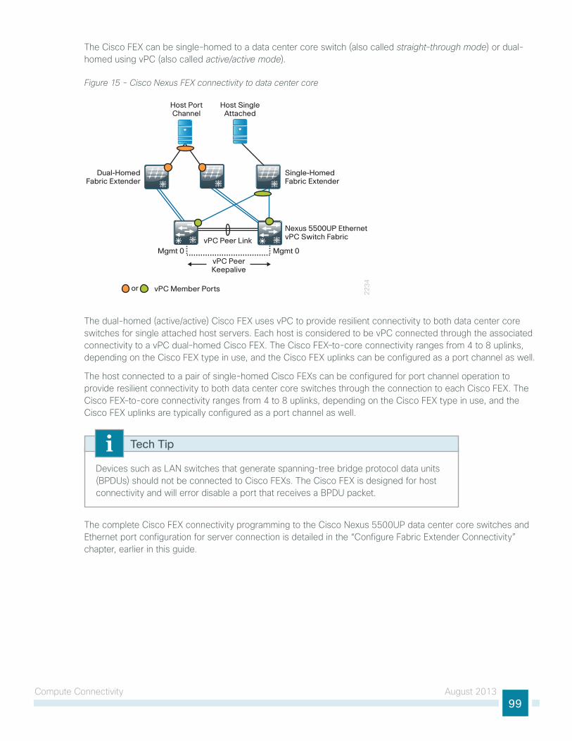
Compute Connectivity August 201399
the Cisco FeX can be single-homed to a data center core switch (also called straight-through mode) or dual-homed using vPC (also called active/active mode).
Figure 15 - Cisco Nexus FEX connectivity to data center core
22
34
vPC PeerKeepalive
vPC Peer LinkMgmt 0 Mgmt 0
vPC Member Portsor
Dual-HomedFabric Extender
Single-HomedFabric Extender
Host PortChannel
Host SingleAttached
Nexus 5500UP EthernetvPC Switch Fabric
the dual-homed (active/active) Cisco FeX uses vPC to provide resilient connectivity to both data center core switches for single attached host servers. each host is considered to be vPC connected through the associated connectivity to a vPC dual-homed Cisco FeX. the Cisco FeX–to-core connectivity ranges from 4 to 8 uplinks, depending on the Cisco FeX type in use, and the Cisco FeX uplinks can be configured as a port channel as well.
the host connected to a pair of single-homed Cisco FeXs can be configured for port channel operation to provide resilient connectivity to both data center core switches through the connection to each Cisco FeX. the Cisco FeX–to-core connectivity ranges from 4 to 8 uplinks, depending on the Cisco FeX type in use, and the Cisco FeX uplinks are typically configured as a port channel as well.
Devices such as lAn switches that generate spanning-tree bridge protocol data units (BPDus) should not be connected to Cisco FeXs. the Cisco FeX is designed for host connectivity and will error disable a port that receives a BPDu packet.
Tech Tip
the complete Cisco FeX connectivity programming to the Cisco nexus 5500uP data center core switches and ethernet port configuration for server connection is detailed in the “Configure Fabric extender Connectivity” chapter, earlier in this guide.
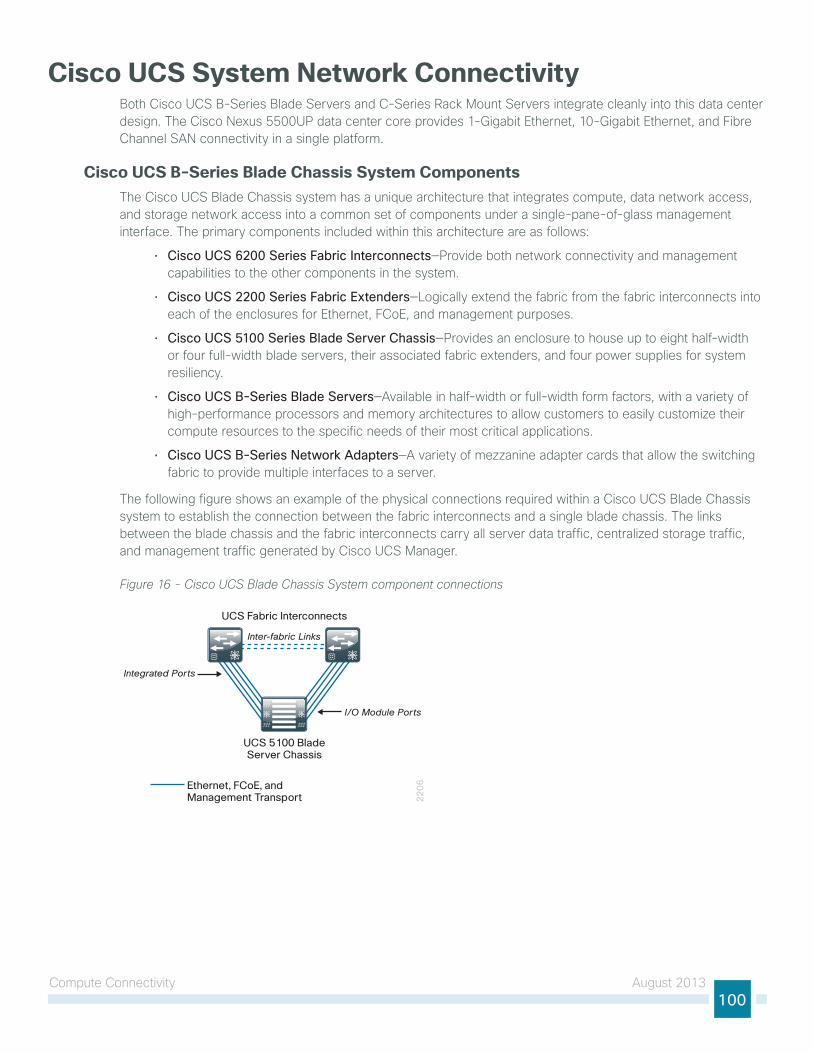
Compute Connectivity August 2013100
Cisco UCS System Network ConnectivityBoth Cisco uCs B-series Blade servers and C-series Rack Mount servers integrate cleanly into this data center design. the Cisco nexus 5500uP data center core provides 1-gigabit ethernet, 10-gigabit ethernet, and Fibre Channel sAn connectivity in a single platform.
Cisco UCS B-Series Blade Chassis System Componentsthe Cisco uCs Blade Chassis system has a unique architecture that integrates compute, data network access, and storage network access into a common set of components under a single-pane-of-glass management interface. the primary components included within this architecture are as follows:
• Cisco UCS 6200 Series Fabric Interconnects—Provide both network connectivity and management capabilities to the other components in the system.
• Cisco UCS 2200 Series Fabric Extenders—logically extend the fabric from the fabric interconnects into each of the enclosures for ethernet, FCoe, and management purposes.
• Cisco UCS 5100 Series Blade Server Chassis—Provides an enclosure to house up to eight half-width or four full-width blade servers, their associated fabric extenders, and four power supplies for system resiliency.
• Cisco UCS B-Series Blade Servers—Available in half-width or full-width form factors, with a variety of high-performance processors and memory architectures to allow customers to easily customize their compute resources to the specific needs of their most critical applications.
• Cisco UCS B-Series Network Adapters—A variety of mezzanine adapter cards that allow the switching fabric to provide multiple interfaces to a server.
the following figure shows an example of the physical connections required within a Cisco uCs Blade Chassis system to establish the connection between the fabric interconnects and a single blade chassis. the links between the blade chassis and the fabric interconnects carry all server data traffic, centralized storage traffic, and management traffic generated by Cisco uCs Manager.
Figure 16 - Cisco UCS Blade Chassis System component connections
22
06
UCS 5100 BladeServer Chassis
UCS Fabric Interconnects
I/O Module Ports
Integrated Ports
Ethernet, FCoE, and Management Transport
Inter-fabric Links
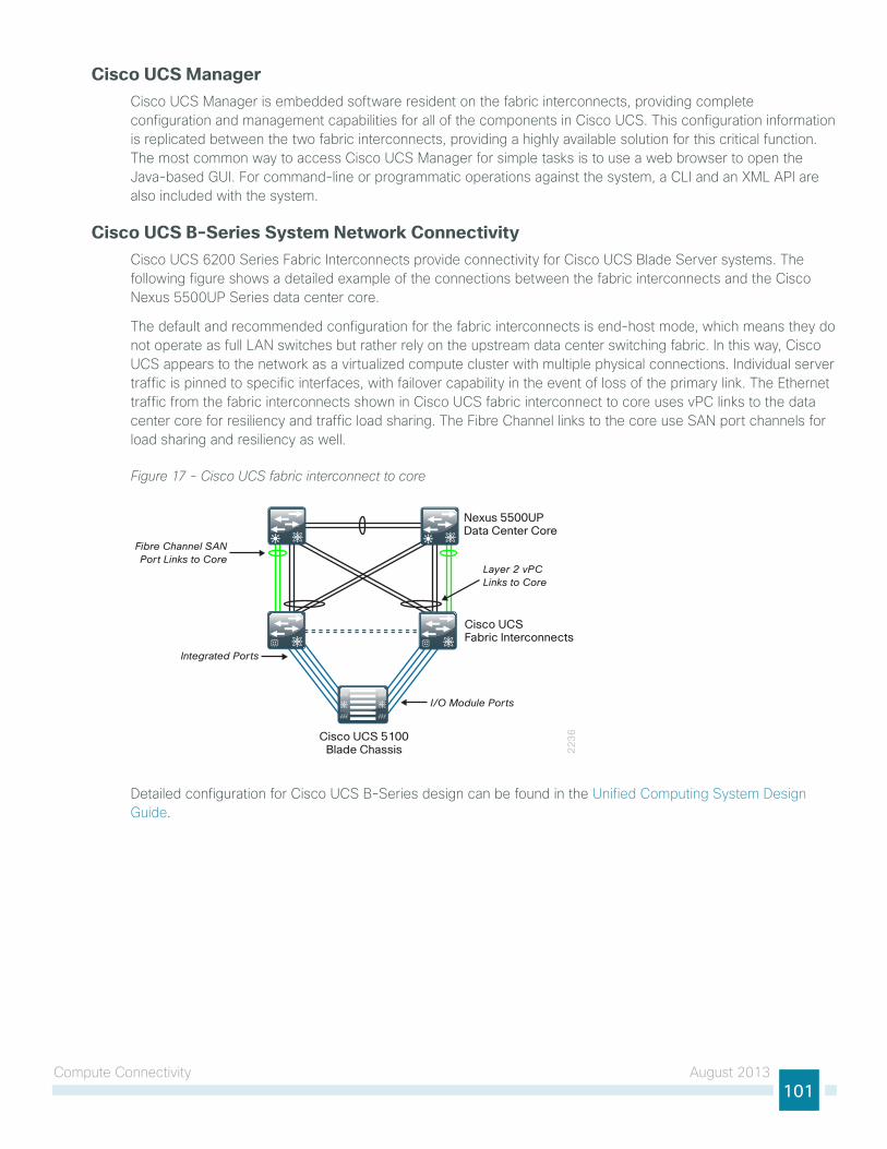
Compute Connectivity August 2013101
Cisco UCS ManagerCisco uCs Manager is embedded software resident on the fabric interconnects, providing complete configuration and management capabilities for all of the components in Cisco uCs. this configuration information is replicated between the two fabric interconnects, providing a highly available solution for this critical function. the most common way to access Cisco uCs Manager for simple tasks is to use a web browser to open the Java-based gui. For command-line or programmatic operations against the system, a Cli and an XMl APi are also included with the system.
Cisco UCS B-Series System Network ConnectivityCisco uCs 6200 series Fabric interconnects provide connectivity for Cisco uCs Blade server systems. the following figure shows a detailed example of the connections between the fabric interconnects and the Cisco nexus 5500uP series data center core.
the default and recommended configuration for the fabric interconnects is end-host mode, which means they do not operate as full lAn switches but rather rely on the upstream data center switching fabric. in this way, Cisco uCs appears to the network as a virtualized compute cluster with multiple physical connections. individual server traffic is pinned to specific interfaces, with failover capability in the event of loss of the primary link. the ethernet traffic from the fabric interconnects shown in Cisco uCs fabric interconnect to core uses vPC links to the data center core for resiliency and traffic load sharing. the Fibre Channel links to the core use sAn port channels for load sharing and resiliency as well.
Figure 17 - Cisco UCS fabric interconnect to core
22
36Cisco UCS 5100
Blade Chassis
Nexus 5500UPData Center Core
Layer 2 vPCLinks to Core
Fibre Channel SANPort Links to Core
I/O Module Ports
Integrated Ports
Cisco UCS Fabric Interconnects
Detailed configuration for Cisco uCs B-series design can be found in the unified Computing system Design guide.
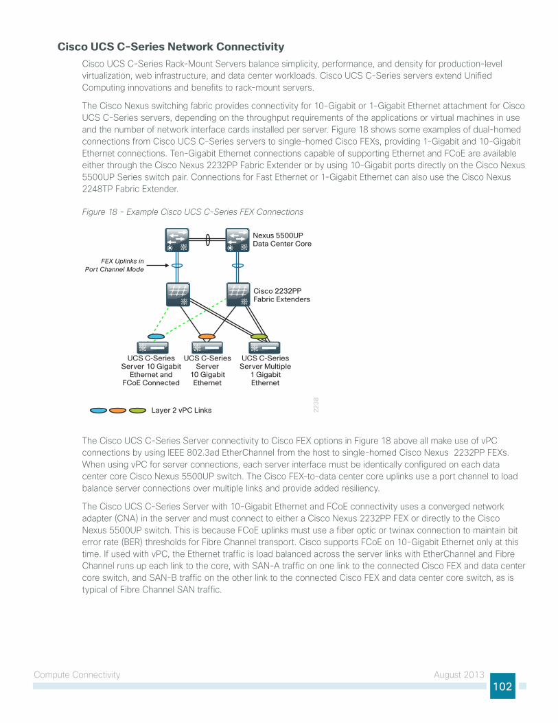
Compute Connectivity August 2013102
Cisco UCS C-Series Network ConnectivityCisco uCs C-series Rack-Mount servers balance simplicity, performance, and density for production-level virtualization, web infrastructure, and data center workloads. Cisco uCs C-series servers extend unified Computing innovations and benefits to rack-mount servers.
the Cisco nexus switching fabric provides connectivity for 10-gigabit or 1-gigabit ethernet attachment for Cisco uCs C-series servers, depending on the throughput requirements of the applications or virtual machines in use and the number of network interface cards installed per server. Figure 18 shows some examples of dual-homed connections from Cisco uCs C-series servers to single-homed Cisco FeXs, providing 1-gigabit and 10-gigabit ethernet connections. ten-gigabit ethernet connections capable of supporting ethernet and FCoe are available either through the Cisco nexus 2232PP Fabric extender or by using 10-gigabit ports directly on the Cisco nexus 5500uP series switch pair. Connections for Fast ethernet or 1-gigabit ethernet can also use the Cisco nexus 2248tP Fabric extender.
Figure 18 - Example Cisco UCS C-Series FEX Connections
22
38
Cisco 2232PPFabric Extenders
Layer 2 vPC Links
Nexus 5500UPData Center Core
UCS C-Series Server 10 Gigabit
Ethernet and FCoE Connected
UCS C-Series Server
10 Gigabit Ethernet
UCS C-Series Server Multiple
1 GigabitEthernet
FEX Uplinks inPort Channel Mode
the Cisco uCs C-series server connectivity to Cisco FeX options in Figure 18 above all make use of vPC connections by using ieee 802.3ad etherChannel from the host to single-homed Cisco nexus 2232PP FeXs. When using vPC for server connections, each server interface must be identically configured on each data center core Cisco nexus 5500uP switch. the Cisco FeX–to–data center core uplinks use a port channel to load balance server connections over multiple links and provide added resiliency.
the Cisco uCs C-series server with 10-gigabit ethernet and FCoe connectivity uses a converged network adapter (CnA) in the server and must connect to either a Cisco nexus 2232PP FeX or directly to the Cisco nexus 5500uP switch. this is because FCoe uplinks must use a fiber optic or twinax connection to maintain bit error rate (BeR) thresholds for Fibre Channel transport. Cisco supports FCoe on 10-gigabit ethernet only at this time. if used with vPC, the ethernet traffic is load balanced across the server links with etherChannel and Fibre Channel runs up each link to the core, with sAn-A traffic on one link to the connected Cisco FeX and data center core switch, and sAn-B traffic on the other link to the connected Cisco FeX and data center core switch, as is typical of Fibre Channel sAn traffic.
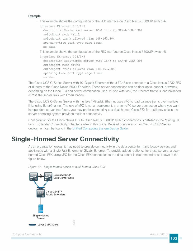
Compute Connectivity August 2013103
Example• this example shows the configuration of the FeX interface on Cisco nexus 5500uP switch-A.interface Ethernet 103/1/3 description Dual-homed server FCoE link to SAN-A VSAN 304 switchport mode trunk switchport trunk allowed vlan 148-163,304 spanning-tree port type edge trunk no shut
• this example shows the configuration of the FeX interface on Cisco nexus 5500uP switch-B.interface Ethernet 104/1/3 description Dual-homed server FCoE link to SAN-B VSAN 305 switchport mode trunk switchport trunk allowed vlan 148-163,305 spanning-tree port type edge trunk no shut
the Cisco uCs C-series server with 10-gigabit ethernet without FCoe can connect to a Cisco nexus 2232 FeX or directly to the Cisco nexus 5500uP switch. these server connections can be fiber optic, copper, or twinax, depending on the Cisco FeX and server combination used. if used with vPC, the ethernet traffic is load balanced across the server links with etherChannel.
the Cisco uCs C-series server with multiple 1-gigabit ethernet uses vPC to load balance traffic over multiple links using etherChannel. the use of vPC is not a requirement. in a non-vPC server connection where you want independent server interfaces, you may prefer connecting to a dual-homed Cisco FeX for resiliency unless the server operating system provides resilient connectivity.
Configuration for the Cisco nexus FeX to Cisco nexus 5500uP switch connections is detailed in the “Configure Fabric extender Connectivity” chapter earlier in this guide. Detailed configuration for Cisco uCs C-series deployment can be found in the unified Computing system Design guide.
Single-Homed Server ConnectivityAs an organization grows, it may need to provide connectivity in the data center for many legacy servers and appliances with a single Fast ethernet or gigabit ethernet. to provide added resiliency for these servers, a dual-homed Cisco FeX using vPC for the Cisco FeX connection to the data center is recommended as shown in the figure below.
Figure 19 - Single-homed server to dual-homed Cisco FEX
22
39
Nexus 5500UP Data Center Core
Cisco 2248TPFabric Extenders
Single-HomedServer
Layer 2 vPC Links
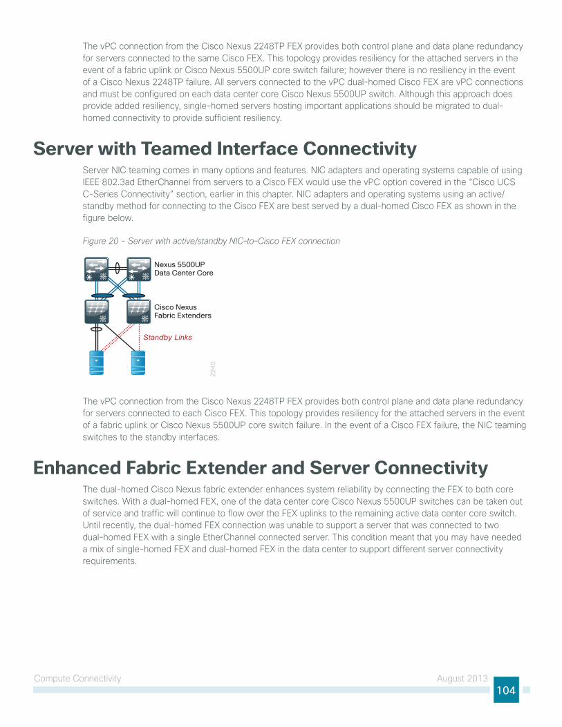
Compute Connectivity August 2013104
the vPC connection from the Cisco nexus 2248tP FeX provides both control plane and data plane redundancy for servers connected to the same Cisco FeX. this topology provides resiliency for the attached servers in the event of a fabric uplink or Cisco nexus 5500uP core switch failure; however there is no resiliency in the event of a Cisco nexus 2248tP failure. All servers connected to the vPC dual-homed Cisco FeX are vPC connections and must be configured on each data center core Cisco nexus 5500uP switch. Although this approach does provide added resiliency, single-homed servers hosting important applications should be migrated to dual-homed connectivity to provide sufficient resiliency.
Server with Teamed Interface Connectivityserver niC teaming comes in many options and features. niC adapters and operating systems capable of using ieee 802.3ad etherChannel from servers to a Cisco FeX would use the vPC option covered in the “Cisco uCs C-series Connectivity” section, earlier in this chapter. niC adapters and operating systems using an active/standby method for connecting to the Cisco FeX are best served by a dual-homed Cisco FeX as shown in the figure below.
Figure 20 - Server with active/standby NIC–to–Cisco FEX connection
22
40
Nexus 5500UP Data Center Core
Cisco NexusFabric Extenders
Standby Links
the vPC connection from the Cisco nexus 2248tP FeX provides both control plane and data plane redundancy for servers connected to each Cisco FeX. this topology provides resiliency for the attached servers in the event of a fabric uplink or Cisco nexus 5500uP core switch failure. in the event of a Cisco FeX failure, the niC teaming switches to the standby interfaces.
Enhanced Fabric Extender and Server Connectivitythe dual-homed Cisco nexus fabric extender enhances system reliability by connecting the FeX to both core switches. With a dual-homed FeX, one of the data center core Cisco nexus 5500uP switches can be taken out of service and traffic will continue to flow over the FeX uplinks to the remaining active data center core switch. until recently, the dual-homed FeX connection was unable to support a server that was connected to two dual-homed FeX with a single etherChannel connected server. this condition meant that you may have needed a mix of single-homed FeX and dual-homed FeX in the data center to support different server connectivity requirements.
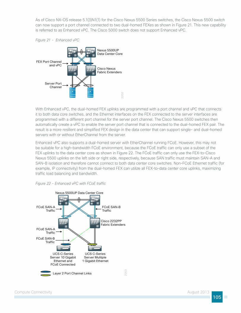
Compute Connectivity August 2013105
As of Cisco nX-os release 5.1(3)n1(1) for the Cisco nexus 5500 series switches, the Cisco nexus 5500 switch can now support a port channel connected to two dual-homed FeXes as shown in Figure 21. this new capability is referred to as enhanced vPC. the Cisco 5000 switch does not support enhanced vPC.
Figure 21 - Enhanced vPC
22
02
Server PortChannel
FEX Port Channeland vPC
Nexus 5500UP Data Center Core
Cisco NexusFabric Extenders
With enhanced vPC, the dual-homed FeX uplinks are programmed with a port channel and vPC that connects it to both data core switches, and the ethernet interfaces on the FeX connected to the server interfaces are programmed with a different port channel for the server port channel. the Cisco nexus 5500 switches then automatically create a vPC to enable the server port channel that is connected to the dual-homed FeX pair. the result is a more resilient and simplified FeX design in the data center that can support single- and dual-homed servers with or without etherChannel from the server.
enhanced vPC also supports a dual-homed server with etherChannel running FCoe. however, this may not be suitable for a high-bandwidth FCoe environment, because the FCoe traffic can only use a subset of the FeX uplinks to the data center core as shown in Figure 22. the FCoe traffic can only use the FeX-to–Cisco nexus 5500 uplinks on the left side or right side, respectively, because sAn traffic must maintain sAn-A and sAn-B isolation and therefore cannot connect to both data center core switches. non-FCoe ethernet traffic (for example, iP connectivity) from the dual-homed FeX can utilize all FeX-to–data center core uplinks, maximizing traffic load balancing and bandwidth.
Figure 22 - Enhanced vPC with FCoE traffic
Cisco 2232PPFabric Extenders
UCS C-SeriesServer 10 Gigabit
Ethernet andFCoE Connected
UCS C-SeriesServer Mulitple
1 Gigabit Ethernet
FCoE SAN-BTraffic
FCoE SAN-ATraffic
FCoE SAN-ATraffic
FCoE SAN-BTraffic
Nexus 5500UP Data Center Core
Layer 2 Port Channel Links 22
03
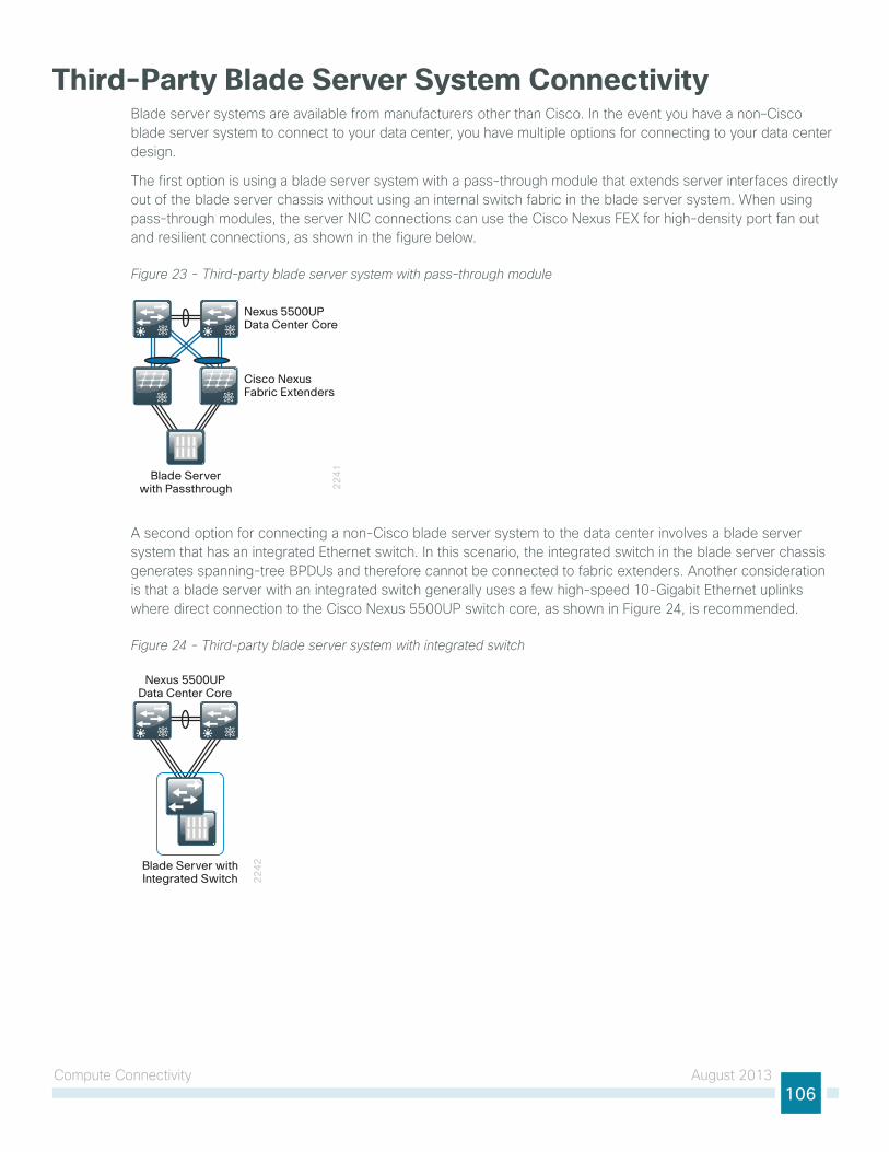
Compute Connectivity August 2013106
Third-Party Blade Server System ConnectivityBlade server systems are available from manufacturers other than Cisco. in the event you have a non–Cisco blade server system to connect to your data center, you have multiple options for connecting to your data center design.
the first option is using a blade server system with a pass-through module that extends server interfaces directly out of the blade server chassis without using an internal switch fabric in the blade server system. When using pass-through modules, the server niC connections can use the Cisco nexus FeX for high-density port fan out and resilient connections, as shown in the figure below.
Figure 23 - Third-party blade server system with pass-through module
22
41
Nexus 5500UP Data Center Core
Cisco NexusFabric Extenders
Blade Serverwith Passthrough
A second option for connecting a non-Cisco blade server system to the data center involves a blade server system that has an integrated ethernet switch. in this scenario, the integrated switch in the blade server chassis generates spanning-tree BPDus and therefore cannot be connected to fabric extenders. Another consideration is that a blade server with an integrated switch generally uses a few high-speed 10-gigabit ethernet uplinks where direct connection to the Cisco nexus 5500uP switch core, as shown in Figure 24, is recommended.
Figure 24 - Third-party blade server system with integrated switch
22
42
Nexus 5500UP Data Center Core
Blade Server with Integrated Switch
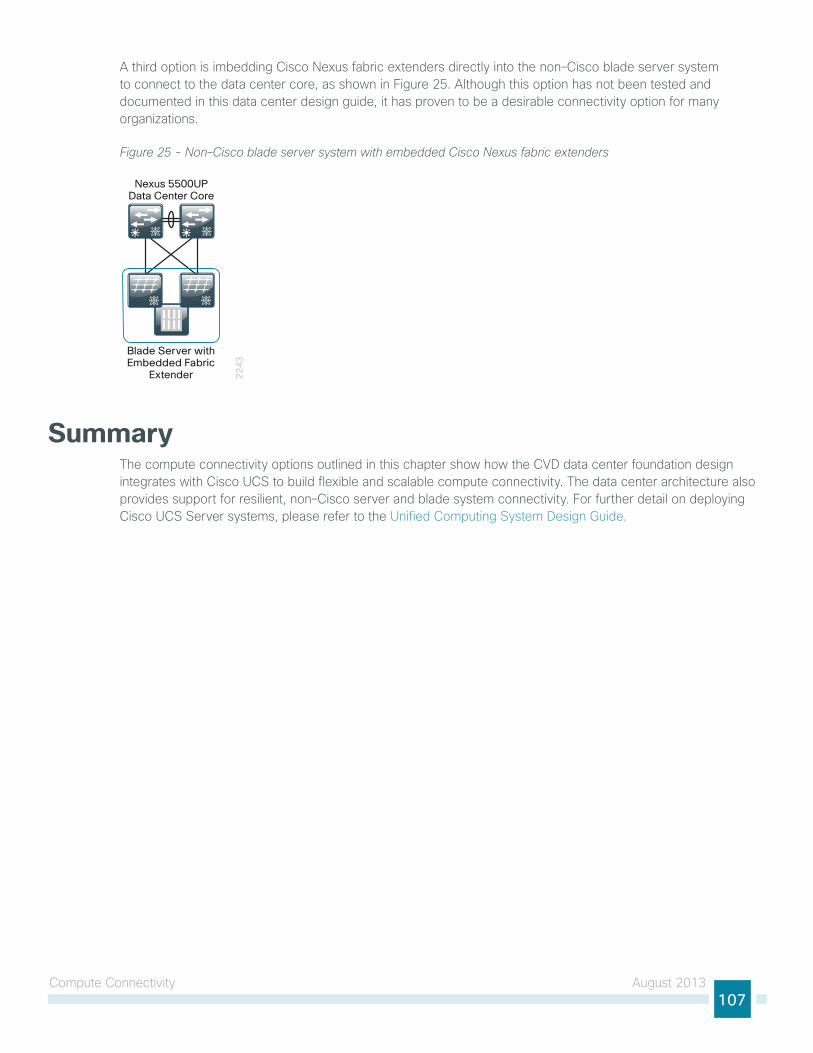
Compute Connectivity August 2013107
A third option is imbedding Cisco nexus fabric extenders directly into the non–Cisco blade server system to connect to the data center core, as shown in Figure 25. Although this option has not been tested and documented in this data center design guide, it has proven to be a desirable connectivity option for many organizations.
Figure 25 - Non–Cisco blade server system with embedded Cisco Nexus fabric extenders
22
43
Blade Server with Embedded Fabric
Extender
Nexus 5500UPData Center Core
Summarythe compute connectivity options outlined in this chapter show how the CVD data center foundation design integrates with Cisco uCs to build flexible and scalable compute connectivity. the data center architecture also provides support for resilient, non–Cisco server and blade system connectivity. For further detail on deploying Cisco uCs server systems, please refer to the unified Computing system Design guide.
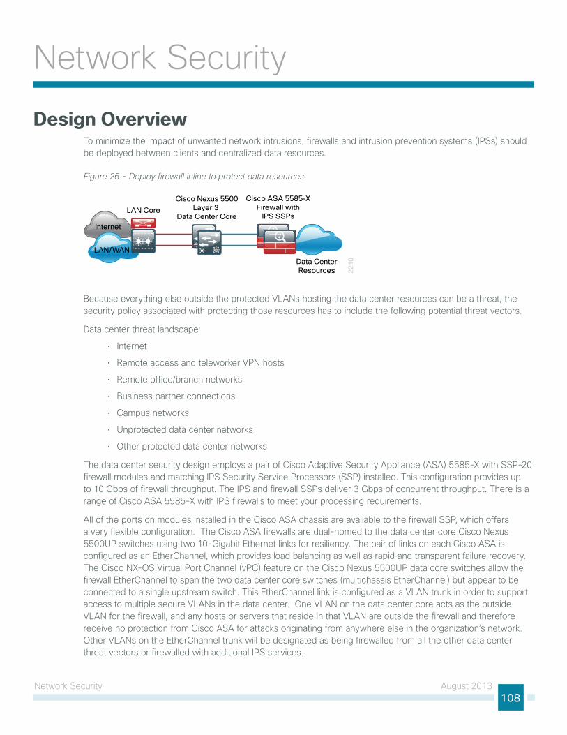
network security August 2013108
network security
Design Overviewto minimize the impact of unwanted network intrusions, firewalls and intrusion prevention systems (iPss) should be deployed between clients and centralized data resources.
Figure 26 - Deploy firewall inline to protect data resources
22
10
Cisco ASA 5585-XFirewall with
IPS SSPsLAN Core
Cisco Nexus 5500Layer 3
Data Center Core
LAN/WAN
Internet
Data CenterResources
Because everything else outside the protected VlAns hosting the data center resources can be a threat, the security policy associated with protecting those resources has to include the following potential threat vectors.
Data center threat landscape:
• internet
• Remote access and teleworker VPn hosts
• Remote office/branch networks
• Business partner connections
• Campus networks
• unprotected data center networks
• other protected data center networks
the data center security design employs a pair of Cisco Adaptive security Appliance (AsA) 5585-X with ssP-20 firewall modules and matching iPs security service Processors (ssP) installed. this configuration provides up to 10 gbps of firewall throughput. the iPs and firewall ssPs deliver 3 gbps of concurrent throughput. there is a range of Cisco AsA 5585-X with iPs firewalls to meet your processing requirements.
All of the ports on modules installed in the Cisco AsA chassis are available to the firewall ssP, which offers a very flexible configuration. the Cisco AsA firewalls are dual-homed to the data center core Cisco nexus 5500uP switches using two 10-gigabit ethernet links for resiliency. the pair of links on each Cisco AsA is configured as an etherChannel, which provides load balancing as well as rapid and transparent failure recovery. the Cisco nX-os Virtual Port Channel (vPC) feature on the Cisco nexus 5500uP data core switches allow the firewall etherChannel to span the two data center core switches (multichassis etherChannel) but appear to be connected to a single upstream switch. this etherChannel link is configured as a VlAn trunk in order to support access to multiple secure VlAns in the data center. one VlAn on the data center core acts as the outside VlAn for the firewall, and any hosts or servers that reside in that VlAn are outside the firewall and therefore receive no protection from Cisco AsA for attacks originating from anywhere else in the organization’s network. other VlAns on the etherChannel trunk will be designated as being firewalled from all the other data center threat vectors or firewalled with additional iPs services.
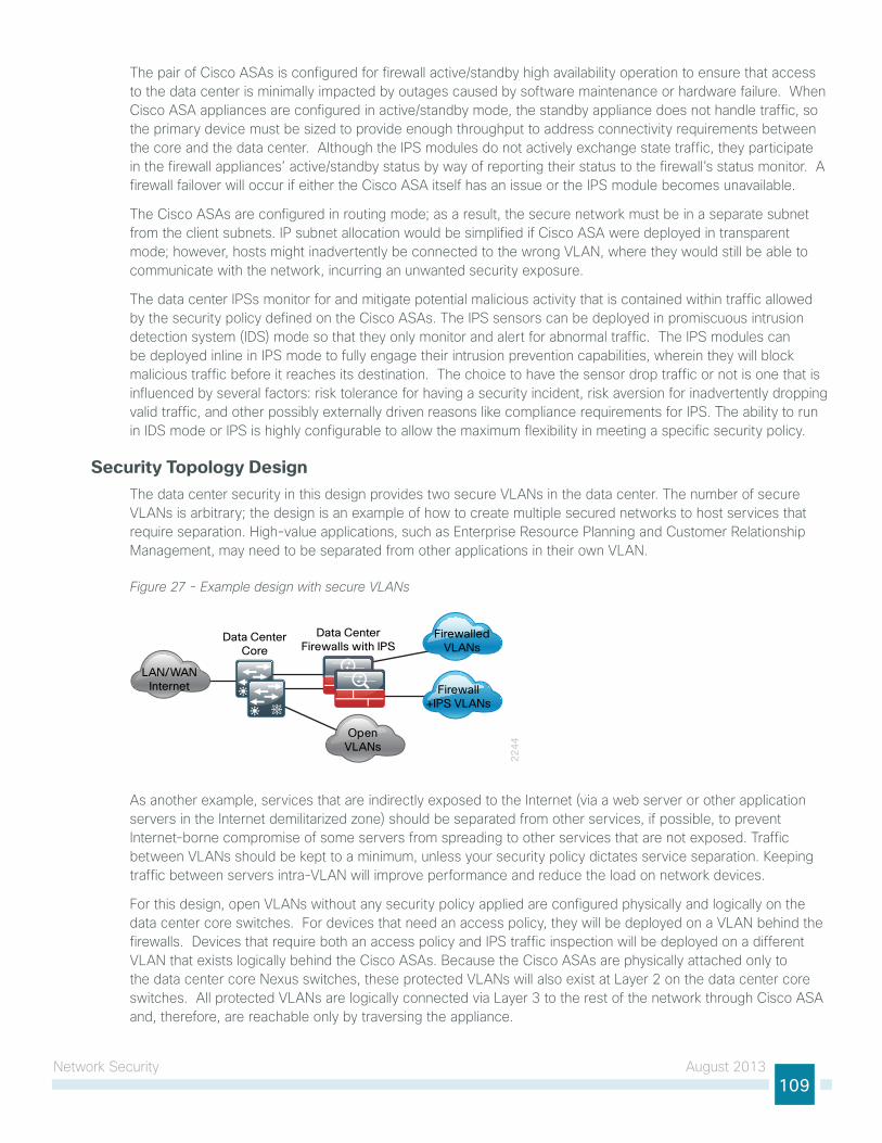
network security August 2013109
the pair of Cisco AsAs is configured for firewall active/standby high availability operation to ensure that access to the data center is minimally impacted by outages caused by software maintenance or hardware failure. When Cisco AsA appliances are configured in active/standby mode, the standby appliance does not handle traffic, so the primary device must be sized to provide enough throughput to address connectivity requirements between the core and the data center. Although the iPs modules do not actively exchange state traffic, they participate in the firewall appliances’ active/standby status by way of reporting their status to the firewall’s status monitor. A firewall failover will occur if either the Cisco AsA itself has an issue or the iPs module becomes unavailable.
the Cisco AsAs are configured in routing mode; as a result, the secure network must be in a separate subnet from the client subnets. iP subnet allocation would be simplified if Cisco AsA were deployed in transparent mode; however, hosts might inadvertently be connected to the wrong VlAn, where they would still be able to communicate with the network, incurring an unwanted security exposure.
the data center iPss monitor for and mitigate potential malicious activity that is contained within traffic allowed by the security policy defined on the Cisco AsAs. the iPs sensors can be deployed in promiscuous intrusion detection system (iDs) mode so that they only monitor and alert for abnormal traffic. the iPs modules can be deployed inline in iPs mode to fully engage their intrusion prevention capabilities, wherein they will block malicious traffic before it reaches its destination. the choice to have the sensor drop traffic or not is one that is influenced by several factors: risk tolerance for having a security incident, risk aversion for inadvertently dropping valid traffic, and other possibly externally driven reasons like compliance requirements for iPs. the ability to run in iDs mode or iPs is highly configurable to allow the maximum flexibility in meeting a specific security policy.
Security Topology Design the data center security in this design provides two secure VlAns in the data center. the number of secure VlAns is arbitrary; the design is an example of how to create multiple secured networks to host services that require separation. high-value applications, such as enterprise Resource Planning and Customer Relationship Management, may need to be separated from other applications in their own VlAn.
Figure 27 - Example design with secure VLANs
22
44
LAN/WANInternet
Data CenterFirewalls with IPS
Data CenterCore
FirewalledVLANs
Firewall+IPS VLANs
OpenVLANs
As another example, services that are indirectly exposed to the internet (via a web server or other application servers in the internet demilitarized zone) should be separated from other services, if possible, to prevent internet-borne compromise of some servers from spreading to other services that are not exposed. traffic between VlAns should be kept to a minimum, unless your security policy dictates service separation. Keeping traffic between servers intra-VlAn will improve performance and reduce the load on network devices.
For this design, open VlAns without any security policy applied are configured physically and logically on the data center core switches. For devices that need an access policy, they will be deployed on a VlAn behind the firewalls. Devices that require both an access policy and iPs traffic inspection will be deployed on a different VlAn that exists logically behind the Cisco AsAs. Because the Cisco AsAs are physically attached only to the data center core nexus switches, these protected VlAns will also exist at layer 2 on the data center core switches. All protected VlAns are logically connected via layer 3 to the rest of the network through Cisco AsA and, therefore, are reachable only by traversing the appliance.
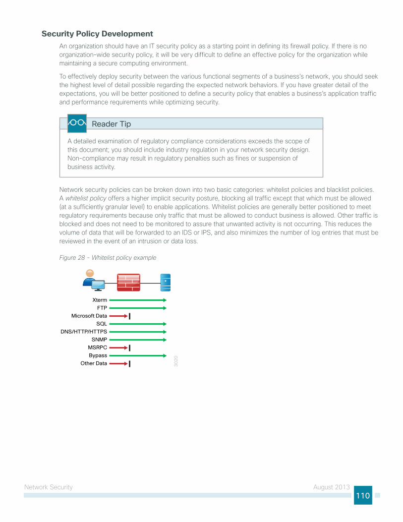
network security August 2013110
Security Policy Development An organization should have an it security policy as a starting point in defining its firewall policy. if there is no organization-wide security policy, it will be very difficult to define an effective policy for the organization while maintaining a secure computing environment.
to effectively deploy security between the various functional segments of a business’s network, you should seek the highest level of detail possible regarding the expected network behaviors. if you have greater detail of the expectations, you will be better positioned to define a security policy that enables a business’s application traffic and performance requirements while optimizing security.
A detailed examination of regulatory compliance considerations exceeds the scope of this document; you should include industry regulation in your network security design. non-compliance may result in regulatory penalties such as fines or suspension of business activity.
Reader Tip
network security policies can be broken down into two basic categories: whitelist policies and blacklist policies. A whitelist policy offers a higher implicit security posture, blocking all traffic except that which must be allowed (at a sufficiently granular level) to enable applications. Whitelist policies are generally better positioned to meet regulatory requirements because only traffic that must be allowed to conduct business is allowed. other traffic is blocked and does not need to be monitored to assure that unwanted activity is not occurring. this reduces the volume of data that will be forwarded to an iDs or iPs, and also minimizes the number of log entries that must be reviewed in the event of an intrusion or data loss.
Figure 28 - Whitelist policy example
30
20
Xterm
FTP
Microsoft Data
SQL
DNS/HTTP/HTTPS
SNMP
MSRPC
Bypass
Other Data
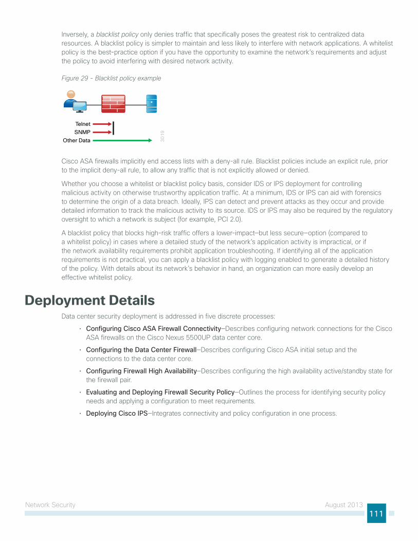
network security August 2013111
inversely, a blacklist policy only denies traffic that specifically poses the greatest risk to centralized data resources. A blacklist policy is simpler to maintain and less likely to interfere with network applications. A whitelist policy is the best-practice option if you have the opportunity to examine the network’s requirements and adjust the policy to avoid interfering with desired network activity.
Figure 29 - Blacklist policy example
30
19
Telnet
SNMP
Other Data
Cisco AsA firewalls implicitly end access lists with a deny-all rule. Blacklist policies include an explicit rule, prior to the implicit deny-all rule, to allow any traffic that is not explicitly allowed or denied.
Whether you choose a whitelist or blacklist policy basis, consider iDs or iPs deployment for controlling malicious activity on otherwise trustworthy application traffic. At a minimum, iDs or iPs can aid with forensics to determine the origin of a data breach. ideally, iPs can detect and prevent attacks as they occur and provide detailed information to track the malicious activity to its source. iDs or iPs may also be required by the regulatory oversight to which a network is subject (for example, PCi 2.0).
A blacklist policy that blocks high-risk traffic offers a lower-impact—but less secure—option (compared to a whitelist policy) in cases where a detailed study of the network’s application activity is impractical, or if the network availability requirements prohibit application troubleshooting. if identifying all of the application requirements is not practical, you can apply a blacklist policy with logging enabled to generate a detailed history of the policy. With details about its network’s behavior in hand, an organization can more easily develop an effective whitelist policy.
Deployment DetailsData center security deployment is addressed in five discrete processes:
• Configuring Cisco ASA Firewall Connectivity—Describes configuring network connections for the Cisco AsA firewalls on the Cisco nexus 5500uP data center core.
• Configuring the Data Center Firewall—Describes configuring Cisco AsA initial setup and the connections to the data center core.
• Configuring Firewall High Availability—Describes configuring the high availability active/standby state for the firewall pair.
• Evaluating and Deploying Firewall Security Policy—outlines the process for identifying security policy needs and applying a configuration to meet requirements.
• Deploying Cisco IPS—integrates connectivity and policy configuration in one process.
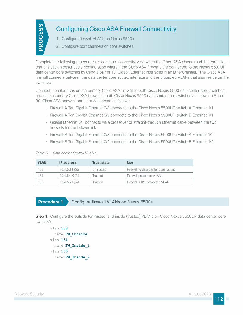
network security August 2013112
Configuring Cisco ASA Firewall Connectivity
1. Configure firewall VlAns on nexus 5500s
2. Configure port channels on core switchesPR
OC
ESS
Complete the following procedures to configure connectivity between the Cisco AsA chassis and the core. note that this design describes a configuration wherein the Cisco AsA firewalls are connected to the nexus 5500uP data center core switches by using a pair of 10-gigabit ethernet interfaces in an etherChannel. the Cisco AsA firewall connects between the data center core–routed interface and the protected VlAns that also reside on the switches.
Connect the interfaces on the primary Cisco AsA firewall to both Cisco nexus 5500 data center core switches, and the secondary Cisco AsA firewall to both Cisco nexus 5500 data center core switches as shown in Figure 30. Cisco AsA network ports are connected as follows:
• Firewall-A ten gigabit ethernet 0/8 connects to the Cisco nexus 5500uP switch-A ethernet 1/1
• Firewall-A ten gigabit ethernet 0/9 connects to the Cisco nexus 5500uP switch-B ethernet 1/1
• gigabit ethernet 0/1 connects via a crossover or straight-through ethernet cable between the two firewalls for the failover link
• Firewall-B ten gigabit ethernet 0/8 connects to the Cisco nexus 5500uP switch-A ethernet 1/2
• Firewall-B ten gigabit ethernet 0/9 connects to the Cisco nexus 5500uP switch-B ethernet 1/2
Table 5 - Data center firewall VLANs
VLAN IP address Trust state Use
153 10.4.53.1 /25 Untrusted Firewall to data center core routing
154 10.4.54.X /24 Trusted Firewall protected VLAN
155 10.4.55.X /24 Trusted Firewall + IPS protected VLAN
Procedure 1 Configure firewall VLANs on Nexus 5500s
Step 1: Configure the outside (untrusted) and inside (trusted) VlAns on Cisco nexus 5500uP data center core switch-A.
vlan 153 name FW_Outsidevlan 154 name FW_Inside_1vlan 155 name FW_Inside_2
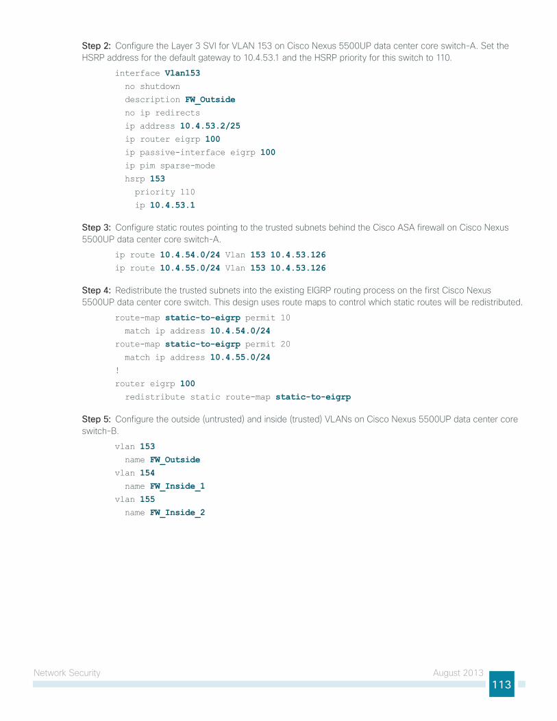
network security August 2013113
Step 2: Configure the layer 3 sVi for VlAn 153 on Cisco nexus 5500uP data center core switch-A. set the hsRP address for the default gateway to 10.4.53.1 and the hsRP priority for this switch to 110.
interface Vlan153 no shutdown
description FW_Outside no ip redirects
ip address 10.4.53.2/25 ip router eigrp 100 ip passive-interface eigrp 100 ip pim sparse-mode
hsrp 153 priority 110
ip 10.4.53.1
Step 3: Configure static routes pointing to the trusted subnets behind the Cisco AsA firewall on Cisco nexus 5500uP data center core switch-A.
ip route 10.4.54.0/24 Vlan 153 10.4.53.126ip route 10.4.55.0/24 Vlan 153 10.4.53.126
Step 4: Redistribute the trusted subnets into the existing eigRP routing process on the first Cisco nexus 5500uP data center core switch. this design uses route maps to control which static routes will be redistributed.
route-map static-to-eigrp permit 10 match ip address 10.4.54.0/24route-map static-to-eigrp permit 20 match ip address 10.4.55.0/24!
router eigrp 100 redistribute static route-map static-to-eigrp
Step 5: Configure the outside (untrusted) and inside (trusted) VlAns on Cisco nexus 5500uP data center core switch-B.
vlan 153 name FW_Outsidevlan 154 name FW_Inside_1vlan 155 name FW_Inside_2
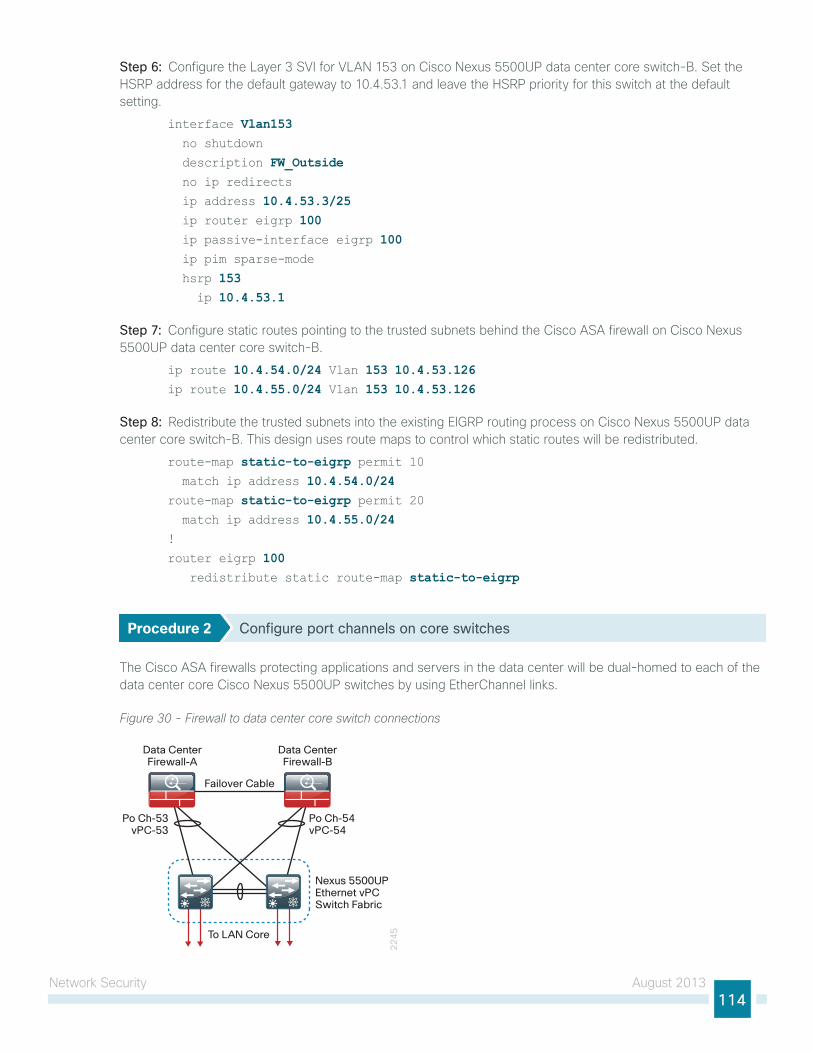
network security August 2013114
Step 6: Configure the layer 3 sVi for VlAn 153 on Cisco nexus 5500uP data center core switch-B. set the hsRP address for the default gateway to 10.4.53.1 and leave the hsRP priority for this switch at the default setting.
interface Vlan153 no shutdown
description FW_Outside no ip redirects
ip address 10.4.53.3/25 ip router eigrp 100 ip passive-interface eigrp 100 ip pim sparse-mode
hsrp 153 ip 10.4.53.1
Step 7: Configure static routes pointing to the trusted subnets behind the Cisco AsA firewall on Cisco nexus 5500uP data center core switch-B.
ip route 10.4.54.0/24 Vlan 153 10.4.53.126ip route 10.4.55.0/24 Vlan 153 10.4.53.126
Step 8: Redistribute the trusted subnets into the existing eigRP routing process on Cisco nexus 5500uP data center core switch-B. this design uses route maps to control which static routes will be redistributed.
route-map static-to-eigrp permit 10 match ip address 10.4.54.0/24route-map static-to-eigrp permit 20 match ip address 10.4.55.0/24!
router eigrp 100 redistribute static route-map static-to-eigrp
Procedure 2 Configure port channels on core switches
the Cisco AsA firewalls protecting applications and servers in the data center will be dual-homed to each of the data center core Cisco nexus 5500uP switches by using etherChannel links.
Figure 30 - Firewall to data center core switch connections
22
45To LAN Core
Nexus 5500UPEthernet vPCSwitch Fabric
Data CenterFirewall-A
Po Ch-53vPC-53
Po Ch-54vPC-54
Data CenterFirewall-B
Failover Cable
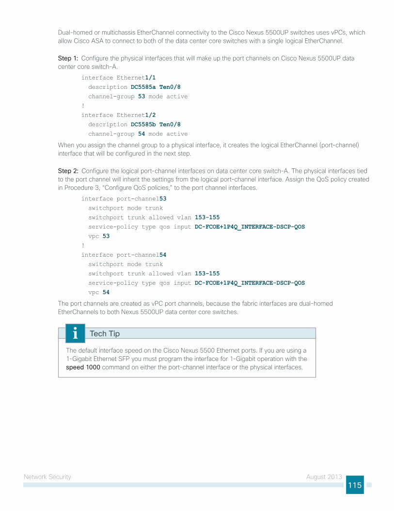
network security August 2013115
Dual-homed or multichassis etherChannel connectivity to the Cisco nexus 5500uP switches uses vPCs, which allow Cisco AsA to connect to both of the data center core switches with a single logical etherChannel.
Step 1: Configure the physical interfaces that will make up the port channels on Cisco nexus 5500uP data center core switch-A.
interface Ethernet1/1 description DC5585a Ten0/8 channel-group 53 mode active!
interface Ethernet1/2 description DC5585b Ten0/8 channel-group 54 mode active
When you assign the channel group to a physical interface, it creates the logical etherChannel (port-channel) interface that will be configured in the next step.
Step 2: Configure the logical port-channel interfaces on data center core switch-A. the physical interfaces tied to the port channel will inherit the settings from the logical port-channel interface. Assign the Qos policy created in Procedure 3, “Configure Qos policies,” to the port channel interfaces.
interface port-channel53 switchport mode trunk
switchport trunk allowed vlan 153-155 service-policy type qos input DC-FCOE+1P4Q_INTERFACE-DSCP-QOS vpc 53!
interface port-channel54 switchport mode trunk
switchport trunk allowed vlan 153-155 service-policy type qos input DC-FCOE+1P4Q_INTERFACE-DSCP-QOS vpc 54
the port channels are created as vPC port channels, because the fabric interfaces are dual-homed etherChannels to both nexus 5500uP data center core switches.
the default interface speed on the Cisco nexus 5500 ethernet ports. if you are using a 1-gigabit ethernet sFP you must program the interface for 1-gigabit operation with the speed 1000 command on either the port-channel interface or the physical interfaces.
Tech Tip
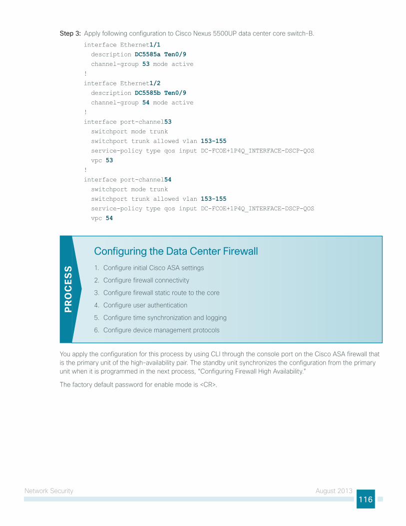
network security August 2013116
Step 3: Apply following configuration to Cisco nexus 5500uP data center core switch-B.
interface Ethernet1/1 description DC5585a Ten0/9 channel-group 53 mode active!
interface Ethernet1/2 description DC5585b Ten0/9 channel-group 54 mode active!
interface port-channel53 switchport mode trunk
switchport trunk allowed vlan 153-155 service-policy type qos input DC-FCOE+1P4Q_INTERFACE-DSCP-QOS
vpc 53!
interface port-channel54 switchport mode trunk
switchport trunk allowed vlan 153-155 service-policy type qos input DC-FCOE+1P4Q_INTERFACE-DSCP-QOS
vpc 54
Configuring the Data Center Firewall
1. Configure initial Cisco AsA settings
2. Configure firewall connectivity
3. Configure firewall static route to the core
4. Configure user authentication
5. Configure time synchronization and logging
6. Configure device management protocols
PR
OC
ESS
you apply the configuration for this process by using Cli through the console port on the Cisco AsA firewall that is the primary unit of the high-availability pair. the standby unit synchronizes the configuration from the primary unit when it is programmed in the next process, “Configuring Firewall high Availability.”
the factory default password for enable mode is <CR>.
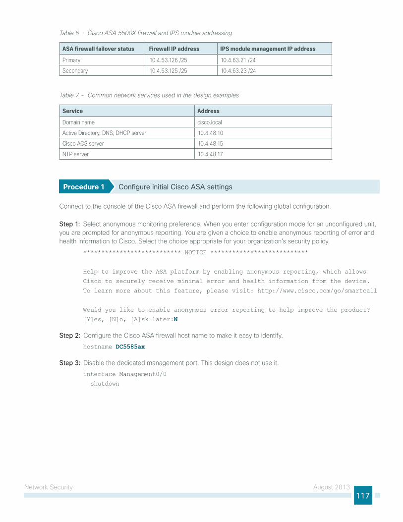
network security August 2013117
Table 6 - Cisco ASA 5500X firewall and IPS module addressing
ASA firewall failover status Firewall IP address IPS module management IP address
Primary 10.4.53.126 /25 10.4.63.21 /24
Secondary 10.4.53.125 /25 10.4.63.23 /24
Table 7 - Common network services used in the design examples
Service Address
Domain name cisco.local
Active Directory, DNS, DHCP server 10.4.48.10
Cisco ACS server 10.4.48.15
NTP server 10.4.48.17
Procedure 1 Configure initial Cisco ASA settings
Connect to the console of the Cisco AsA firewall and perform the following global configuration.
Step 1: select anonymous monitoring preference. When you enter configuration mode for an unconfigured unit, you are prompted for anonymous reporting. you are given a choice to enable anonymous reporting of error and health information to Cisco. select the choice appropriate for your organization’s security policy.
*************************** NOTICE ***************************
Help to improve the ASA platform by enabling anonymous reporting, which allows
Cisco to securely receive minimal error and health information from the device.
To learn more about this feature, please visit: http://www.cisco.com/go/smartcall
Would you like to enable anonymous error reporting to help improve the product?
[Y]es, [N]o, [A]sk later:N
Step 2: Configure the Cisco AsA firewall host name to make it easy to identify.
hostname DC5585ax
Step 3: Disable the dedicated management port. this design does not use it.
interface Management0/0
shutdown
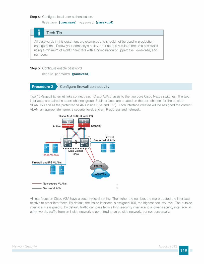
network security August 2013118
Step 4: Configure local user authentication.
Username [username] password [password]
All passwords in this document are examples and should not be used in production configurations. Follow your company’s policy, or—if no policy exists—create a password using a minimum of eight characters with a combination of uppercase, lowercase, and numbers.
Tech Tip
Step 5: Configure enable password.
enable password [password]
Procedure 2 Configure firewall connectivity
two 10-gigabit ethernet links connect each Cisco AsA chassis to the two core Cisco nexus switches. the two interfaces are paired in a port channel group. subinterfaces are created on the port channel for the outside VlAn 153 and all the protected VlAns inside (154 and 155). each interface created will be assigned the correct VlAn, an appropriate name, a security level, and an iP address and netmask.
22
11Non-secure VLANs
Secure VLANs
Open VLANs
Cisco ASA 5585-X with IPS
Active Standby
Firewall Protected VLANs
Firewall and IPS VLANs
Data CenterCore
LAN/WAN
Internet
All interfaces on Cisco AsA have a security-level setting. the higher the number, the more trusted the interface, relative to other interfaces. By default, the inside interface is assigned 100, the highest security level. the outside interface is assigned 0. By default, traffic can pass from a high-security interface to a lower-security interface. in other words, traffic from an inside network is permitted to an outside network, but not conversely.
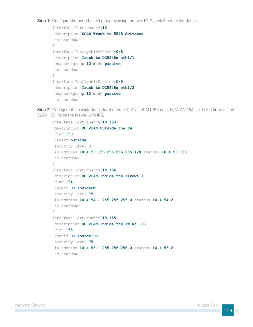
network security August 2013119
Step 1: Configure the port channel group by using the two 10-gigabit ethernet interfaces.
interface Port-channel10 description ECLB Trunk to 5548 Switches no shutdown
!
interface TenGigabitEthernet0/8 description Trunk to DC5548x eth1/1 channel-group 10 mode passive no shutdown
!
interface TenGigabitEthernet0/9 description Trunk to DC5548x eth1/2 channel-group 10 mode passive no shutdown
Step 2: Configure the subinterfaces for the three VlAns: VlAn 153 outside, VlAn 154 inside the firewall, and VlAn 155 inside the firewall with iPs.
interface Port-channel10.153 description DC VLAN Outside the FW vlan 153 nameif outside security-level 0
ip address 10.4.53.126 255.255.255.128 standby 10.4.53.125 no shutdown
!
interface Port-channel10.154 description DC VLAN Inside the Firewall vlan 154 nameif DC-InsideFW security-level 75 ip address 10.4.54.1 255.255.255.0 standby 10.4.54.2 no shutdown
!
interface Port-channel10.155 description DC VLAN Inside the FW w/ IPS vlan 155 nameif DC-InsideIPS security-level 75 ip address 10.4.55.1 255.255.255.0 standby 10.4.55.2 no shutdown
network security August 2013120
Procedure 3 Configure firewall static route to the core
Because the Cisco AsAs are the gateway to the secure VlAns in the data center, the Cisco AsA pair is configured to use a static route to the hsRP address of the Cisco nexus switches on outside VlAn 153.
Step 1: Configure the static route pointing to the data center core hsRP address on the Cisco AsA pair.
route outside 0.0.0.0 0.0.0.0 10.4.53.1 1
Procedure 4 Configure user authentication
(Optional)if you want to reduce operational tasks per device, configure centralized user authentication by using the tACACs+ protocol to authenticate management logins on the infrastructure devices to the AAA server.
As networks scale in the number of devices to maintain, there is an operational burden to maintain local user accounts on every device also scales. A centralized AAA service reduces operational tasks per device and provides an audit log of user access for security compliance and root-cause analysis. When AAA is enabled for access control, it controls all management access to the network infrastructure devices (ssh and httPs).
tACACs+ is the primary protocol used to authenticate management logins on the infrastructure devices to the AAA server. A local AAA user database was defined already to provide a fallback authentication source in case the centralized tACACs+ server is unavailable.
Step 1: Configure the tACACs+ server.
aaa-server AAA-SERVER protocol tacacs+aaa-server AAA-SERVER (outside) host 10.4.48.15 SecretKey
Step 2: Configure the appliance’s management authentication to use the tACACs+ server first, and then the local user database if the tACACs+ server is unavailable.
aaa authentication enable console AAA-SERVER LOCALaaa authentication ssh console AAA-SERVER LOCALaaa authentication http console AAA-SERVER LOCALaaa authentication serial console AAA-SERVER LOCAL
Step 3: Configure the appliance to use AAA to authorize management users.
aaa authorization exec authentication-server
user authorization on the Cisco AsA firewall, unlike Cisco ios devices, does not automatically present the user with the enable prompt if they have a privilege level of 15.
Tech Tip
network security August 2013121
Procedure 5 Configure time synchronization and logging
logging and monitoring are critical aspects of network security devices to support troubleshooting and policy-compliance auditing.
ntP is designed to synchronize time across a network of devices. An ntP network usually gets its time from an authoritative time source, such as a radio clock or an atomic clock attached to a time server. ntP then distributes this time across the organization’s network.
network devices should be programmed to synchronize to a local ntP server in the network. the local ntP server typically references a more accurate clock feed from an outside source.
there is a range of detail that can be logged on the appliance. informational-level logging provides the ideal balance between detail and log-message volume. lower log levels produce fewer messages, but they do not produce enough detail to effectively audit network activity. higher log levels produce a larger volume of messages, but they do not add sufficient value to justify the number of messages logged.
Step 1: Configure the ntP server iP address.
ntp server 10.4.48.17
Step 2: Configure the time zone.
clock timezone PST -8 0clock summer-time PDT recurring
Step 3: Configure which logs to store on the appliance.
logging enable
logging buffered informational
Procedure 6 Configure device management protocols
Cisco Adaptive security Device Manager (AsDM) requires that the appliance’s httPs server be available. Be sure that the configuration includes networks where administrative staff has access to the device through Cisco AsDM; the appliance can offer controlled Cisco AsDM access for a single address or management subnet (in this case, 10.4.48.0/24).
httPs and ssh are more secure replacements for the httP and telnet protocols. they use ssl and tls to provide device authentication and data encryption.
use ssh and httPs protocols in order to more securely manage the device. Both protocols are encrypted for privacy, and the unsecure protocols—telnet and httP—are turned off.
snMP is enabled to allow the network infrastructure devices to be managed by a network management system (nMs). snMPv2c is configured for a read-only community string.
Step 1: Allow internal administrators to remotely manage the appliance over httPs and ssh.
domain-name cisco.local http server enable
http 10.4.48.0 255.255.255.0 outside ssh 10.4.48.0 255.255.255.0 outsidessh version 2
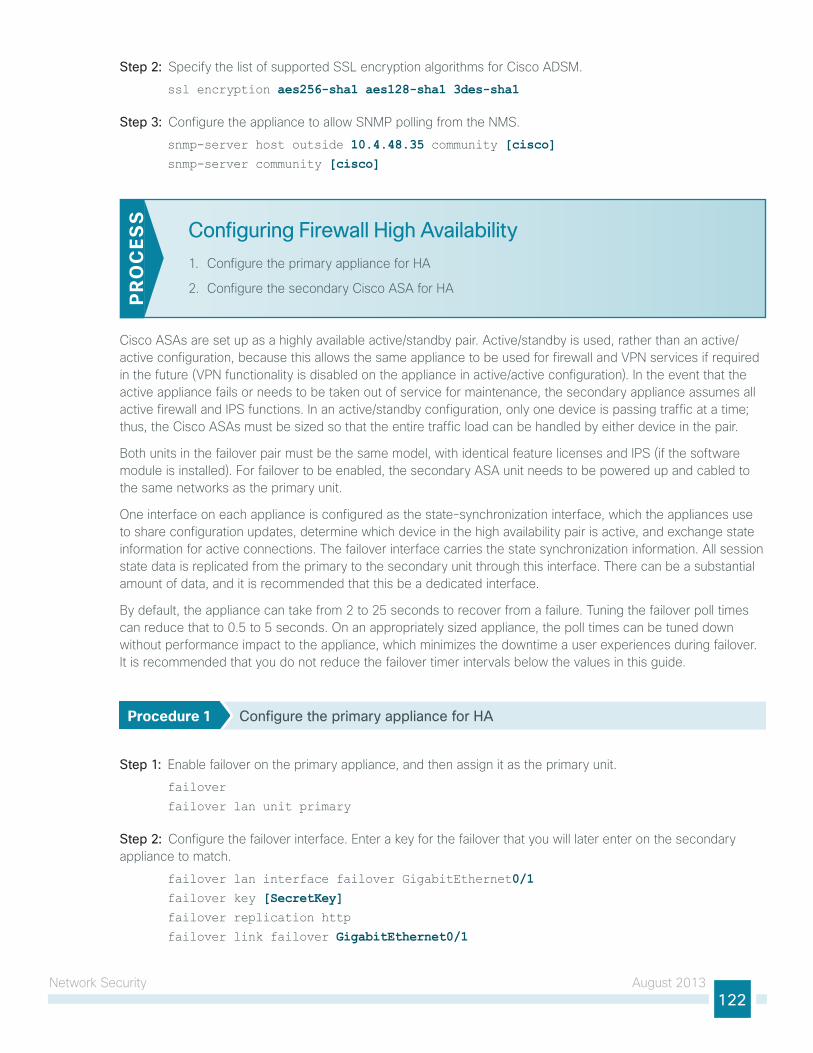
network security August 2013122
Step 2: specify the list of supported ssl encryption algorithms for Cisco ADsM.
ssl encryption aes256-sha1 aes128-sha1 3des-sha1
Step 3: Configure the appliance to allow snMP polling from the nMs.
snmp-server host outside 10.4.48.35 community [cisco]snmp-server community [cisco]
Configuring Firewall High Availability
1. Configure the primary appliance for hA
2. Configure the secondary Cisco AsA for hAPR
OC
ESS
Cisco AsAs are set up as a highly available active/standby pair. Active/standby is used, rather than an active/active configuration, because this allows the same appliance to be used for firewall and VPn services if required in the future (VPn functionality is disabled on the appliance in active/active configuration). in the event that the active appliance fails or needs to be taken out of service for maintenance, the secondary appliance assumes all active firewall and iPs functions. in an active/standby configuration, only one device is passing traffic at a time; thus, the Cisco AsAs must be sized so that the entire traffic load can be handled by either device in the pair.
Both units in the failover pair must be the same model, with identical feature licenses and iPs (if the software module is installed). For failover to be enabled, the secondary AsA unit needs to be powered up and cabled to the same networks as the primary unit.
one interface on each appliance is configured as the state-synchronization interface, which the appliances use to share configuration updates, determine which device in the high availability pair is active, and exchange state information for active connections. the failover interface carries the state synchronization information. All session state data is replicated from the primary to the secondary unit through this interface. there can be a substantial amount of data, and it is recommended that this be a dedicated interface.
By default, the appliance can take from 2 to 25 seconds to recover from a failure. tuning the failover poll times can reduce that to 0.5 to 5 seconds. on an appropriately sized appliance, the poll times can be tuned down without performance impact to the appliance, which minimizes the downtime a user experiences during failover. it is recommended that you do not reduce the failover timer intervals below the values in this guide.
Procedure 1 Configure the primary appliance for HA
Step 1: enable failover on the primary appliance, and then assign it as the primary unit.
failover
failover lan unit primary
Step 2: Configure the failover interface. enter a key for the failover that you will later enter on the secondary appliance to match.
failover lan interface failover GigabitEthernet0/1failover key [SecretKey]failover replication http
failover link failover GigabitEthernet0/1
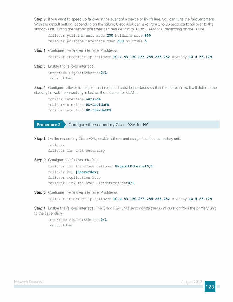
network security August 2013123
Step 3: if you want to speed up failover in the event of a device or link failure, you can tune the failover timers. With the default setting, depending on the failure, Cisco AsA can take from 2 to 25 seconds to fail over to the standby unit. tuning the failover poll times can reduce that to 0.5 to 5 seconds, depending on the failure.
failover polltime unit msec 200 holdtime msec 800failover polltime interface msec 500 holdtime 5
Step 4: Configure the failover interface iP address.
failover interface ip failover 10.4.53.130 255.255.255.252 standby 10.4.53.129
Step 5: enable the failover interface.
interface GigabitEthernet0/1 no shutdown
Step 6: Configure failover to monitor the inside and outside interfaces so that the active firewall will defer to the standby firewall if connectivity is lost on the data center VlAns.
monitor-interface outsidemonitor-interface DC-InsideFWmonitor-interface DC-InsideIPS
Procedure 2 Configure the secondary Cisco ASA for HA
Step 1: on the secondary Cisco AsA, enable failover and assign it as the secondary unit.
failover
failover lan unit secondary
Step 2: Configure the failover interface.
failover lan interface failover GigabitEthernet0/1 failover key [SecretKey] failover replication http
failover link failover GigabitEthernet0/1
Step 3: Configure the failover interface iP address.
failover interface ip failover 10.4.53.130 255.255.255.252 standby 10.4.53.129
Step 4: enable the failover interface. the Cisco AsA units synchronize their configuration from the primary unit to the secondary.
interface GigabitEthernet0/1 no shutdown
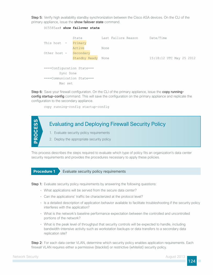
network security August 2013124
Step 5: Verify high availability standby synchronization between the Cisco AsA devices. on the Cli of the primary appliance, issue the show failover state command.
DC5585ax# show failover state
State Last Failure Reason Date/Time
This host - Primary
Active None
Other host - Secondary
Standby Ready None 15:18:12 UTC May 25 2012
====Configuration State===
Sync Done
====Communication State===
Mac set
Step 6: save your firewall configuration. on the Cli of the primary appliance, issue the copy running-config startup-config command. this will save the configuration on the primary appliance and replicate the configuration to the secondary appliance.
copy running-config startup-config
Evaluating and Deploying Firewall Security Policy
1. evaluate security policy requirements
2. Deploy the appropriate security policyPR
OC
ESS
this process describes the steps required to evaluate which type of policy fits an organization’s data center security requirements and provides the procedures necessary to apply these policies.
Procedure 1 Evaluate security policy requirements
Step 1: evaluate security policy requirements by answering the following questions:
• What applications will be served from the secure data center?
• Can the applications’ traffic be characterized at the protocol level?
• is a detailed description of application behavior available to facilitate troubleshooting if the security policy interferes with the application?
• What is the network’s baseline performance expectation between the controlled and uncontrolled portions of the network?
• What is the peak level of throughput that security controls will be expected to handle, including bandwidth-intensive activity such as workstation backups or data transfers to a secondary data replication site?
Step 2: For each data center VlAn, determine which security policy enables application requirements. each firewall VlAn requires either a permissive (blacklist) or restrictive (whitelist) security policy.
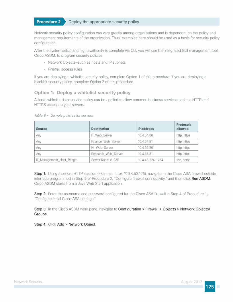
network security August 2013125
Procedure 2 Deploy the appropriate security policy
network security policy configuration can vary greatly among organizations and is dependent on the policy and management requirements of the organization. thus, examples here should be used as a basis for security policy configuration.
After the system setup and high availability is complete via Cli, you will use the integrated gui management tool, Cisco AsDM, to program security policies:
• network objects—such as hosts and iP subnets
• Firewall access rules
if you are deploying a whitelist security policy, complete option 1 of this procedure. if you are deploying a blacklist security policy, complete option 2 of this procedure.
Option 1: Deploy a whitelist security policy A basic whitelist data-service policy can be applied to allow common business services such as httP and httPs access to your servers.
Table 8 - Sample policies for servers
Source Destination IP addressProtocols allowed
Any IT_Web_Server 10.4.54.80 http, https
Any Finance_Web_Server 10.4.54.81 http, https
Any Hr_Web_Server 10.4.55.80 http, https
Any Research_Web_Server 10.4.55.81 http, https
IT_Management_Host_Range Server Room VLANs 10.4.48.224 – 254 ssh, snmp
Step 1: using a secure httP session (example: https://10.4.53.126), navigate to the Cisco AsA firewall outside interface programmed in step 2 of Procedure 2, “Configure firewall connectivity,” and then click Run ASDM. Cisco AsDM starts from a Java Web start application.
Step 2: enter the username and password configured for the Cisco AsA firewall in step 4 of Procedure 1, “Configure initial Cisco AsA settings.”
Step 3: in the Cisco AsDM work pane, navigate to Configuration > Firewall > Objects > Network Objects/Groups.
Step 4: Click Add > Network Object.
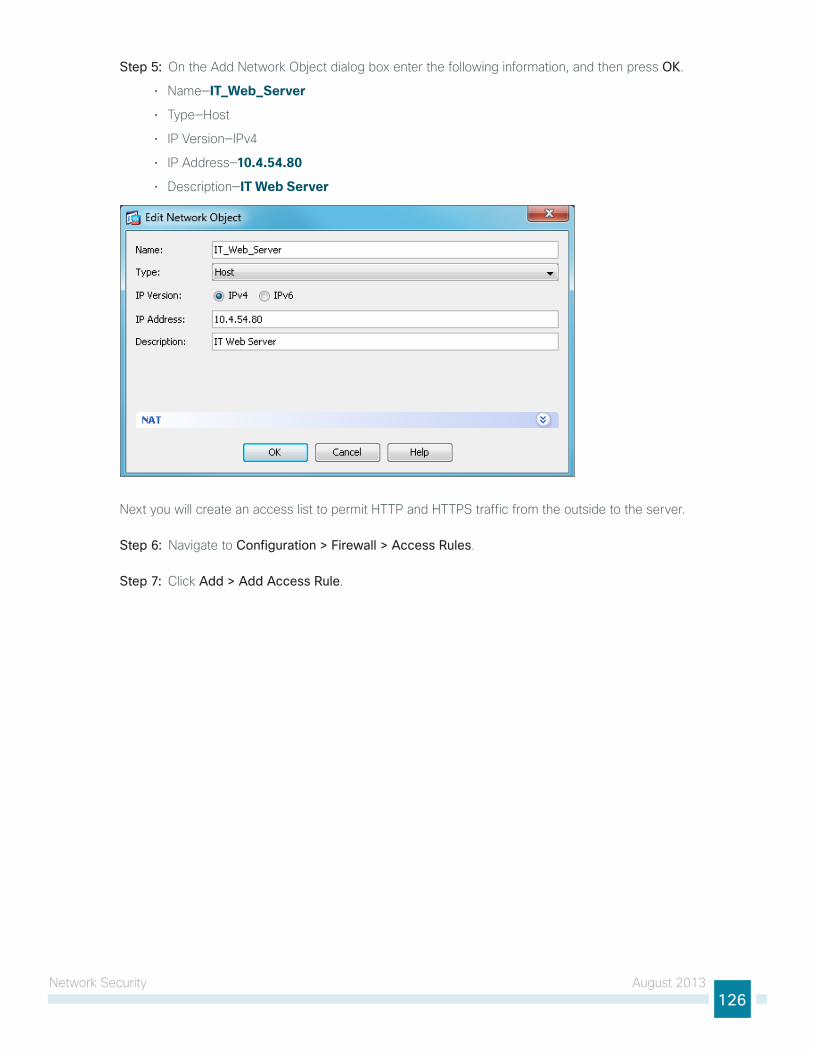
network security August 2013126
Step 5: on the Add network object dialog box enter the following information, and then press OK.
• name—IT_Web_Server
• type—host
• iP Version—iPv4
• iP Address—10.4.54.80
• Description—IT Web Server
next you will create an access list to permit httP and httPs traffic from the outside to the server.
Step 6: navigate to Configuration > Firewall > Access Rules.
Step 7: Click Add > Add Access Rule.
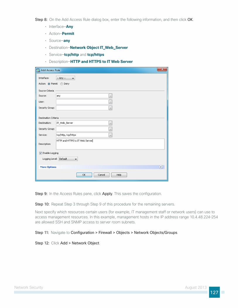
network security August 2013127
Step 8: on the Add Access Rule dialog box, enter the following information, and then click OK.
• interface—Any
• Action—Permit
• source—any
• Destination—Network Object IT_Web_Server
• service—tcp/http and tcp/https
• Description—HTTP and HTTPS to IT Web Server
Step 9: in the Access Rules pane, click Apply. this saves the configuration.
Step 10: Repeat step 3 through step 9 of this procedure for the remaining servers.
next specify which resources certain users (for example, it management staff or network users) can use to access management resources. in this example, management hosts in the iP address range 10.4.48.224–254 are allowed ssh and snMP access to server room subnets.
Step 11: navigate to Configuration > Firewall > Objects > Network Objects/Groups.
Step 12: Click Add > Network Object.
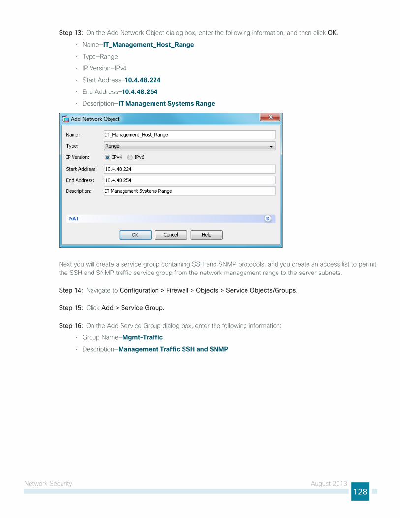
network security August 2013128
Step 13: on the Add network object dialog box, enter the following information, and then click OK.
• name—IT_Management_Host_Range
• type—Range
• iP Version—iPv4
• start Address—10.4.48.224
• end Address—10.4.48.254
• Description—IT Management Systems Range
next you will create a service group containing ssh and snMP protocols, and you create an access list to permit the ssh and snMP traffic service group from the network management range to the server subnets.
Step 14: navigate to Configuration > Firewall > Objects > Service Objects/Groups.
Step 15: Click Add > Service Group.
Step 16: on the Add service group dialog box, enter the following information:
• group name—Mgmt-Traffic
• Description—Management Traffic SSH and SNMP
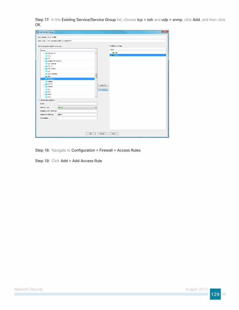
network security August 2013129
Step 17: in the Existing Service/Service Group list, choose tcp > ssh and udp > snmp, click Add, and then click OK.
Step 18: navigate to Configuration > Firewall > Access Rules.
Step 19: Click Add > Add Access Rule.
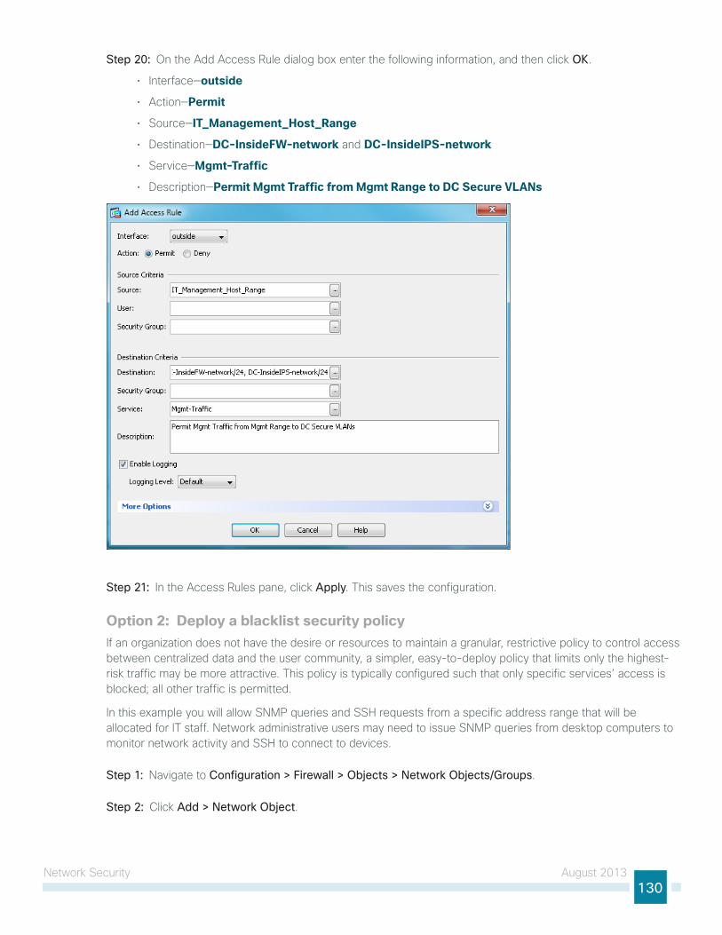
network security August 2013130
Step 20: on the Add Access Rule dialog box enter the following information, and then click OK.
• interface—outside
• Action—Permit
• source—IT_Management_Host_Range
• Destination—DC-InsideFW-network and DC-InsideIPS-network
• service—Mgmt-Traffic
• Description—Permit Mgmt Traffic from Mgmt Range to DC Secure VLANs
Step 21: in the Access Rules pane, click Apply. this saves the configuration.
Option 2: Deploy a blacklist security policyif an organization does not have the desire or resources to maintain a granular, restrictive policy to control access between centralized data and the user community, a simpler, easy-to-deploy policy that limits only the highest-risk traffic may be more attractive. this policy is typically configured such that only specific services’ access is blocked; all other traffic is permitted.
in this example you will allow snMP queries and ssh requests from a specific address range that will be allocated for it staff. network administrative users may need to issue snMP queries from desktop computers to monitor network activity and ssh to connect to devices.
Step 1: navigate to Configuration > Firewall > Objects > Network Objects/Groups.
Step 2: Click Add > Network Object.

network security August 2013131
Step 3: on the Add network object dialog box, enter the following information, and then click OK.
• name—IT_Management_Host_Range
• type—Range
• iP Version—IPv4
• start Address—10.4.48.224
• end Address—10.4.48.254
• Description—IT Management Systems Range
next you will create a service group containing ssh and snMP protocols, and you will also create an access list to permit the ssh and snMP traffic service group from the network management range to the server subnets.
Step 4: navigate to Configuration > Firewall > Objects > Service Objects/Groups.
Step 5: Click Add > Service Group.
Step 6: on the Add service group dialog box enter the following information:
• group name—Mgmt-Traffic
• Description—Management Traffic SSH and SNMP
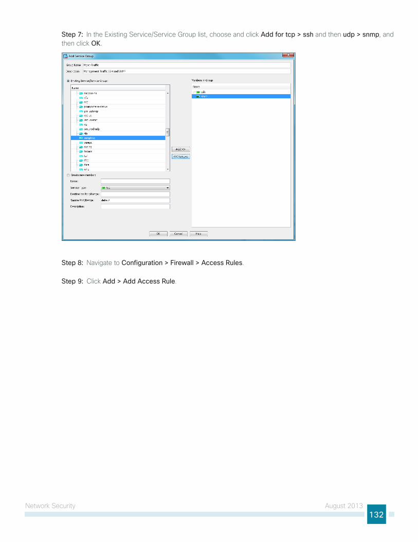
network security August 2013132
Step 7: in the existing service/service group list, choose and click Add for tcp > ssh and then udp > snmp, and then click OK.
Step 8: navigate to Configuration > Firewall > Access Rules.
Step 9: Click Add > Add Access Rule.
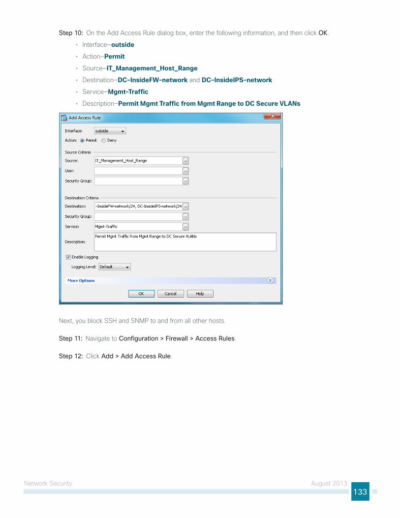
network security August 2013133
Step 10: on the Add Access Rule dialog box, enter the following information, and then click OK.
• interface—outside
• Action—Permit
• source—IT_Management_Host_Range
• Destination—DC-InsideFW-network and DC-InsideIPS-network
• service—Mgmt-Traffic
• Description—Permit Mgmt Traffic from Mgmt Range to DC Secure VLANs
next, you block ssh and snMP to and from all other hosts.
Step 11: navigate to Configuration > Firewall > Access Rules.
Step 12: Click Add > Add Access Rule.
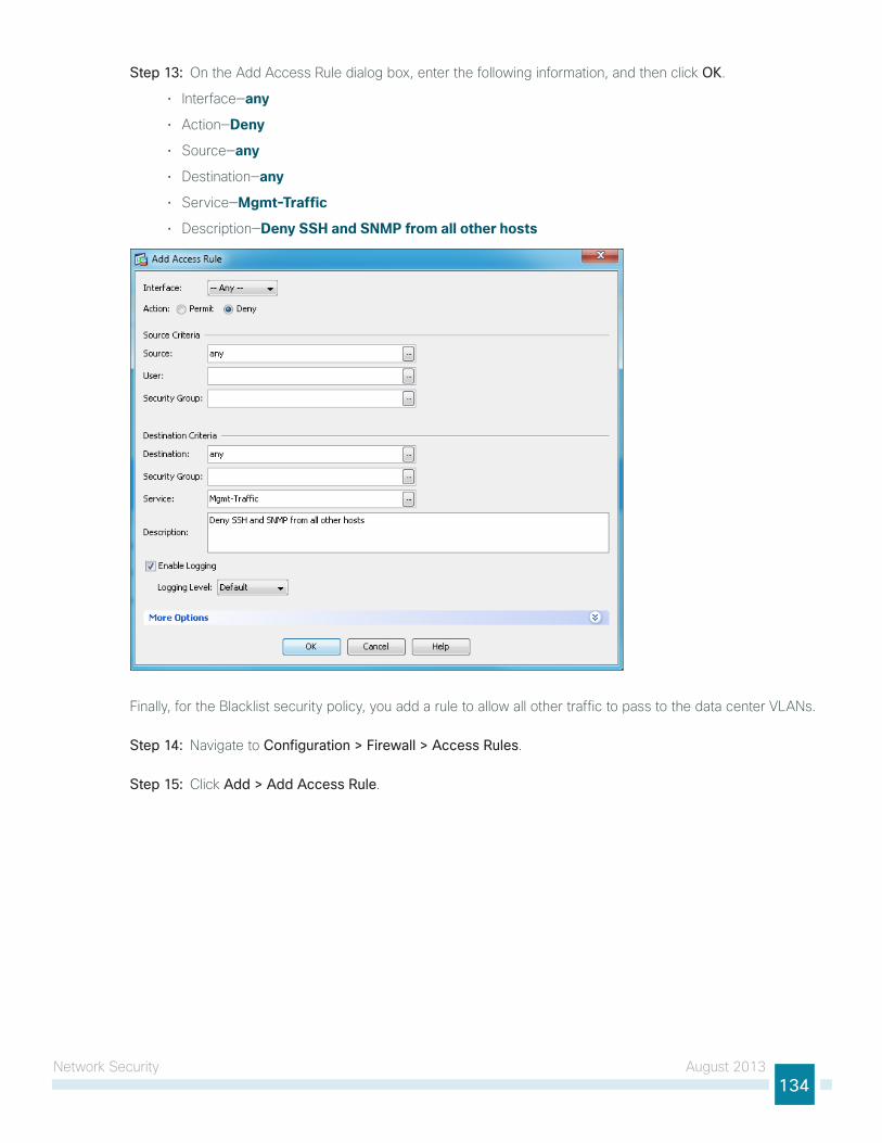
network security August 2013134
Step 13: on the Add Access Rule dialog box, enter the following information, and then click OK.
• interface—any
• Action—Deny
• source—any
• Destination—any
• service—Mgmt-Traffic
• Description—Deny SSH and SNMP from all other hosts
Finally, for the Blacklist security policy, you add a rule to allow all other traffic to pass to the data center VlAns.
Step 14: navigate to Configuration > Firewall > Access Rules.
Step 15: Click Add > Add Access Rule.
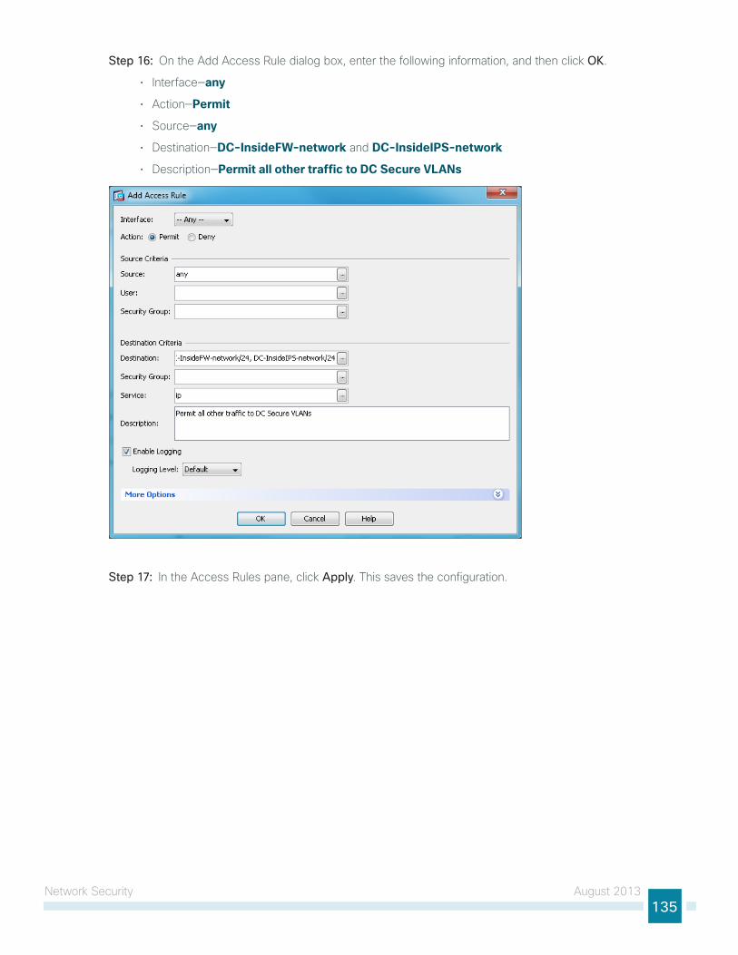
network security August 2013135
Step 16: on the Add Access Rule dialog box, enter the following information, and then click OK.
• interface—any
• Action—Permit
• source—any
• Destination—DC-InsideFW-network and DC-InsideIPS-network
• Description—Permit all other traffic to DC Secure VLANs
Step 17: in the Access Rules pane, click Apply. this saves the configuration.
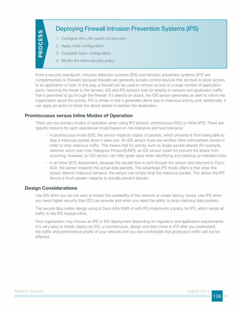
network security August 2013136
Deploying Firewall Intrusion Prevention Systems (IPS)
1. Configure the lAn switch access port
2. Apply initial configuration
3. Complete basic configuration
4. Modify the inline security policy
PR
OC
ESS
From a security standpoint, intrusion detection systems (iDs) and intrusion prevention systems (iPs) are complementary to firewalls because firewalls are generally access-control devices that are built to block access to an application or host. in this way, a firewall can be used to remove access to a large number of application ports, reducing the threat to the servers. iDs and iPs sensors look for attacks in network and application traffic that is permitted to go through the firewall. if it detects an attack, the iDs sensor generates an alert to inform the organization about the activity. iPs is similar in that it generates alerts due to malicious activity and, additionally, it can apply an action to block the attack before it reaches the destination.
Promiscuous versus Inline Modes of Operationthere are two primary modes of operation when using iPs sensors: promiscuous (iDs) or inline (iPs). there are specific reasons for each operational model based on risk tolerance and fault tolerance:
• in promiscuous mode (iDs), the sensor inspects copies of packets, which prevents it from being able to stop a malicious packet when it sees one. An iDs sensor must use another inline enforcement device in order to stop malicious traffic. this means that for activity such as single-packet attacks (for example, slammer worm over user Datagram Protocol[uDP]), an iDs sensor could not prevent the attack from occurring. however, an iDs sensor can offer great value when identifying and cleaning up infected hosts.
• in an inline (iPs) deployment, because the packet flow is sent through the sensor and returned to Cisco AsA, the sensor inspects the actual data packets. the advantage iPs mode offers is that when the sensor detects malicious behavior, the sensor can simply drop the malicious packet. this allows the iPs device a much greater capacity to actually prevent attacks.
Design Considerationsuse iDs when you do not want to impact the availability of the network or create latency issues. use iPs when you need higher security than iDs can provide and when you need the ability to drop malicious data packets.
the secure data center design using a Cisco AsA 5585-X with iPs implements a policy for iPs, which sends all traffic to the iPs module inline.
your organization may choose an iPs or iDs deployment depending on regulatory and application requirements. it is very easy to initially deploy an iDs, or promiscuous, design and then move to iPs after you understand the traffic and performance profile of your network and you are comfortable that production traffic will not be affected.
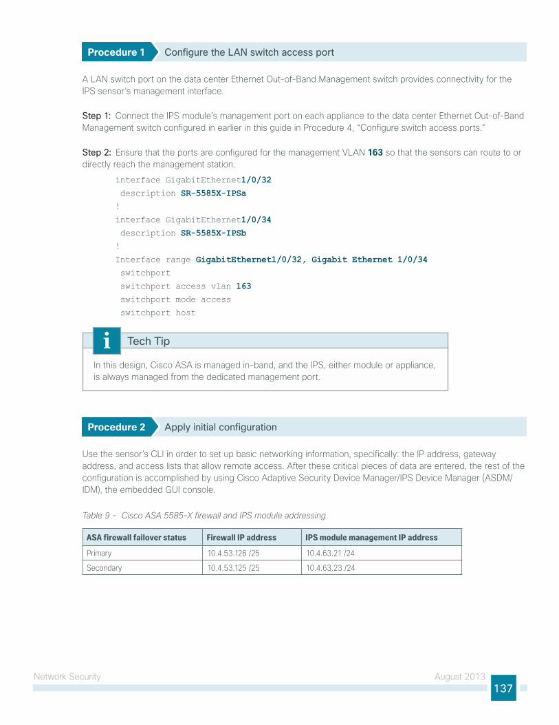
network security August 2013137
Procedure 1 Configure the LAN switch access port
A lAn switch port on the data center ethernet out-of-Band Management switch provides connectivity for the iPs sensor’s management interface.
Step 1: Connect the iPs module’s management port on each appliance to the data center ethernet out-of-Band Management switch configured in earlier in this guide in Procedure 4, “Configure switch access ports.”
Step 2: ensure that the ports are configured for the management VlAn 163 so that the sensors can route to or directly reach the management station.
interface GigabitEthernet1/0/32 description SR-5585X-IPSa!
interface GigabitEthernet1/0/34 description SR-5585X-IPSb!
Interface range GigabitEthernet1/0/32, Gigabit Ethernet 1/0/34 switchport
switchport access vlan 163 switchport mode access
switchport host
in this design, Cisco AsA is managed in-band, and the iPs, either module or appliance, is always managed from the dedicated management port.
Tech Tip
Procedure 2 Apply initial configuration
use the sensor’s Cli in order to set up basic networking information, specifically: the iP address, gateway address, and access lists that allow remote access. After these critical pieces of data are entered, the rest of the configuration is accomplished by using Cisco Adaptive security Device Manager/iPs Device Manager (AsDM/iDM), the embedded gui console.
Table 9 - Cisco ASA 5585-X firewall and IPS module addressing
ASA firewall failover status Firewall IP address IPS module management IP address
Primary 10.4.53.126 /25 10.4.63.21 /24
Secondary 10.4.53.125 /25 10.4.63.23 /24
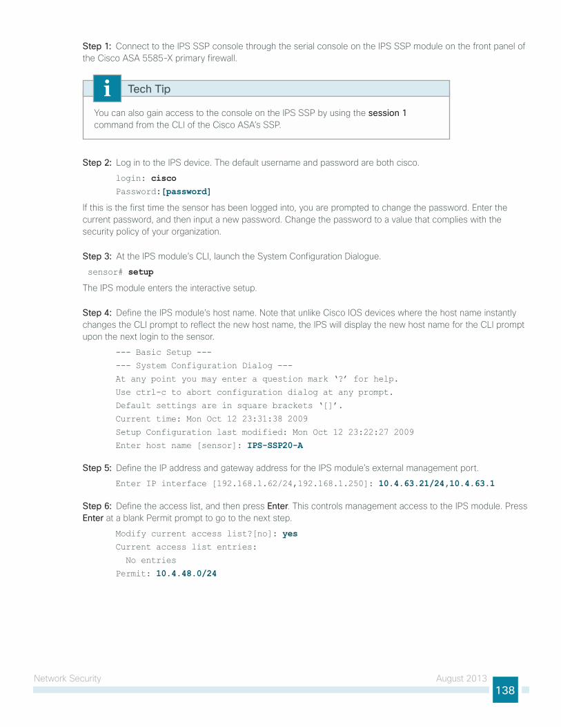
network security August 2013138
Step 1: Connect to the iPs ssP console through the serial console on the iPs ssP module on the front panel of the Cisco AsA 5585-X primary firewall.
you can also gain access to the console on the iPs ssP by using the session 1 command from the Cli of the Cisco AsA’s ssP.
Tech Tip
Step 2: log in to the iPs device. the default username and password are both cisco.
login: cisco Password:[password]
if this is the first time the sensor has been logged into, you are prompted to change the password. enter the current password, and then input a new password. Change the password to a value that complies with the security policy of your organization.
Step 3: At the iPs module’s Cli, launch the system Configuration Dialogue.
sensor# setup
the iPs module enters the interactive setup.
Step 4: Define the iPs module’s host name. note that unlike Cisco ios devices where the host name instantly changes the Cli prompt to reflect the new host name, the iPs will display the new host name for the Cli prompt upon the next login to the sensor.
--- Basic Setup ---
--- System Configuration Dialog ---
At any point you may enter a question mark ‘?’ for help.
Use ctrl-c to abort configuration dialog at any prompt.
Default settings are in square brackets ‘[]’.
Current time: Mon Oct 12 23:31:38 2009
Setup Configuration last modified: Mon Oct 12 23:22:27 2009
Enter host name [sensor]: IPS-SSP20-A
Step 5: Define the iP address and gateway address for the iPs module’s external management port.
Enter IP interface [192.168.1.62/24,192.168.1.250]: 10.4.63.21/24,10.4.63.1
Step 6: Define the access list, and then press Enter. this controls management access to the iPs module. Press Enter at a blank Permit prompt to go to the next step.
Modify current access list?[no]: yesCurrent access list entries:
No entries
Permit: 10.4.48.0/24
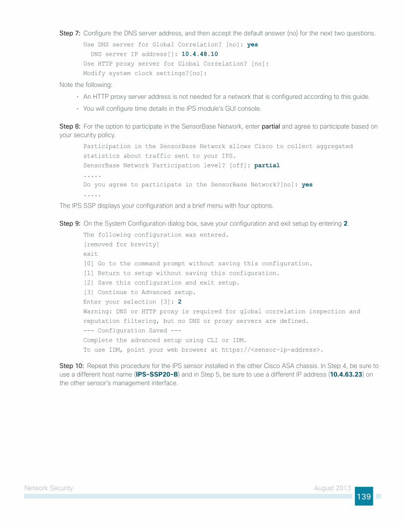
network security August 2013139
Step 7: Configure the Dns server address, and then accept the default answer (no) for the next two questions.
Use DNS server for Global Correlation? [no]: yes DNS server IP address[]: 10.4.48.10Use HTTP proxy server for Global Correlation? [no]:
Modify system clock settings?[no]:
note the following:
• An httP proxy server address is not needed for a network that is configured according to this guide.
• you will configure time details in the iPs module’s gui console.
Step 8: For the option to participate in the sensorBase network, enter partial and agree to participate based on your security policy.
Participation in the SensorBase Network allows Cisco to collect aggregated
statistics about traffic sent to your IPS.
SensorBase Network Participation level? [off]: partial.....
Do you agree to participate in the SensorBase Network?[no]: yes.....
the iPs ssP displays your configuration and a brief menu with four options.
Step 9: on the system Configuration dialog box, save your configuration and exit setup by entering 2.
The following configuration was entered.
[removed for brevity]
exit
[0] Go to the command prompt without saving this configuration.
[1] Return to setup without saving this configuration.
[2] Save this configuration and exit setup.
[3] Continue to Advanced setup.
Enter your selection [3]: 2 Warning: DNS or HTTP proxy is required for global correlation inspection and
reputation filtering, but no DNS or proxy servers are defined.
--- Configuration Saved ---
Complete the advanced setup using CLI or IDM.
To use IDM, point your web browser at https://<sensor-ip-address>.
Step 10: Repeat this procedure for the iPs sensor installed in the other Cisco AsA chassis. in step 4, be sure to use a different host name (IPS-SSP20-B) and in step 5, be sure to use a different iP address (10.4.63.23) on the other sensor’s management interface.
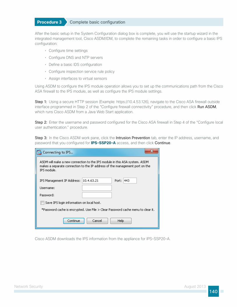
network security August 2013140
Procedure 3 Complete basic configuration
After the basic setup in the system Configuration dialog box is complete, you will use the startup wizard in the integrated management tool, Cisco AsDM/iDM, to complete the remaining tasks in order to configure a basic iPs configuration:
• Configure time settings
• Configure Dns and ntP servers
• Define a basic iDs configuration
• Configure inspection service rule policy
• Assign interfaces to virtual sensors
using AsDM to configure the iPs module operation allows you to set up the communications path from the Cisco AsA firewall to the iPs module, as well as configure the iPs module settings.
Step 1: using a secure httP session (example: https://10.4.53.126), navigate to the Cisco AsA firewall outside interface programmed in step 2 of the “Configure firewall connectivity” procedure, and then click Run ASDM, which runs Cisco AsDM from a Java Web start application.
Step 2: enter the username and password configured for the Cisco AsA firewall in step 4 of the “Configure local user authentication.” procedure.
Step 3: in the Cisco AsDM work pane, click the Intrusion Prevention tab, enter the iP address, username, and password that you configured for IPS-SSP20-A access, and then click Continue.
Cisco AsDM downloads the iPs information from the appliance for iPs-ssP20-A.
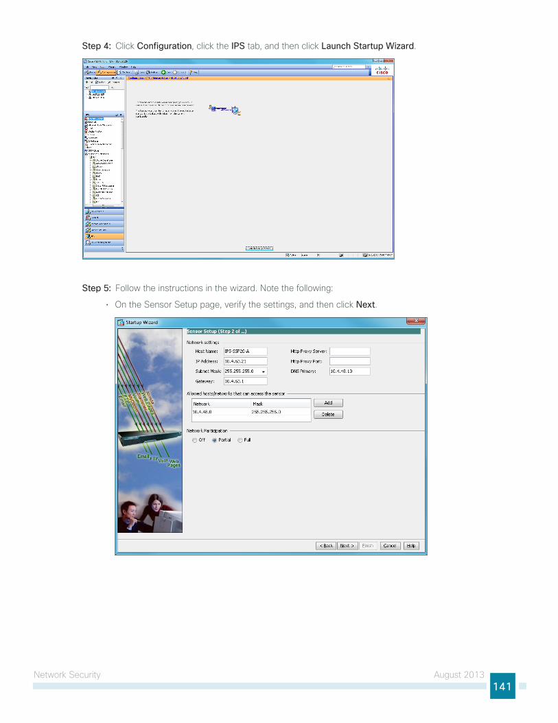
network security August 2013141
Step 4: Click Configuration, click the IPS tab, and then click Launch Startup Wizard.
Step 5: Follow the instructions in the wizard. note the following:
• on the sensor setup page, verify the settings, and then click Next.
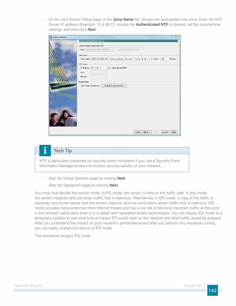
network security August 2013142
• on the next sensor setup page, in the Zone Name list, choose the appropriate time zone. enter the ntP server iP address (example: 10.4.48.17), ensure the Authenticated NTP is cleared, set the summertime settings, and then click Next.
ntP is particularly important for security event correlation if you use a security event information Manager product to monitor security activity on your network.
Tech Tip
• skip the Virtual sensors page by clicking Next.
• skip the signatures page by clicking Next.
you must now decide the sensor mode. in iPs mode, the sensor is inline in the traffic path. in this mode, the sensor inspects—and can drop—traffic that is malicious. Alternatively, in iDs mode, a copy of the traffic is passively sent to the sensor and the sensor inspects—and can send alerts about—traffic that is malicious. iPs mode provides more protection from internet threats and has a low risk of blocking important traffic at this point in the network, particularly when it is coupled with reputation-based technologies. you can deploy iDs mode as a temporary solution to see what kind of impact iPs would have on the network and what traffic would be stopped. After you understand the impact on your network’s performance and after you perform any necessary tuning, you can easily change the sensor to iPs mode.
this procedure assigns iPs mode.
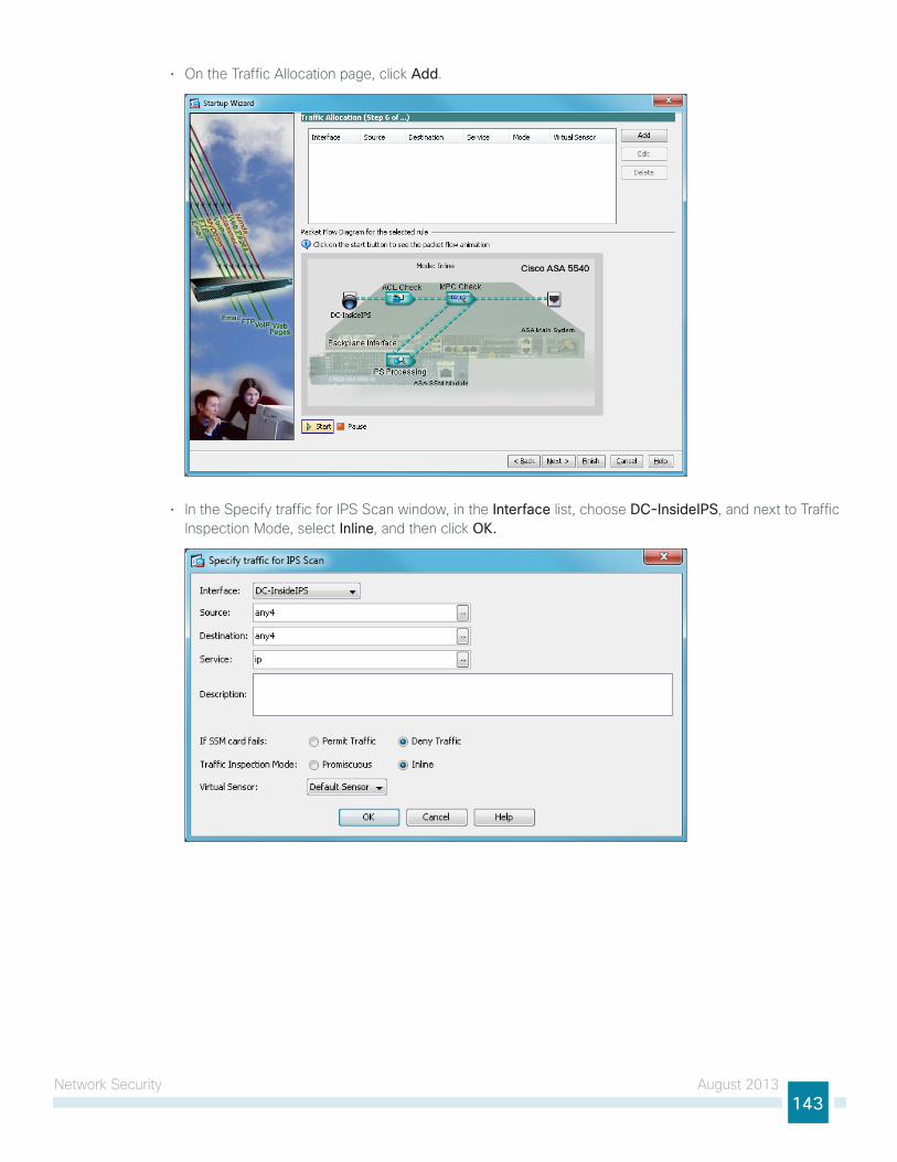
network security August 2013143
• on the traffic Allocation page, click Add.
• in the specify traffic for iPs scan window, in the Interface list, choose DC-InsideIPS, and next to traffic inspection Mode, select Inline, and then click OK.
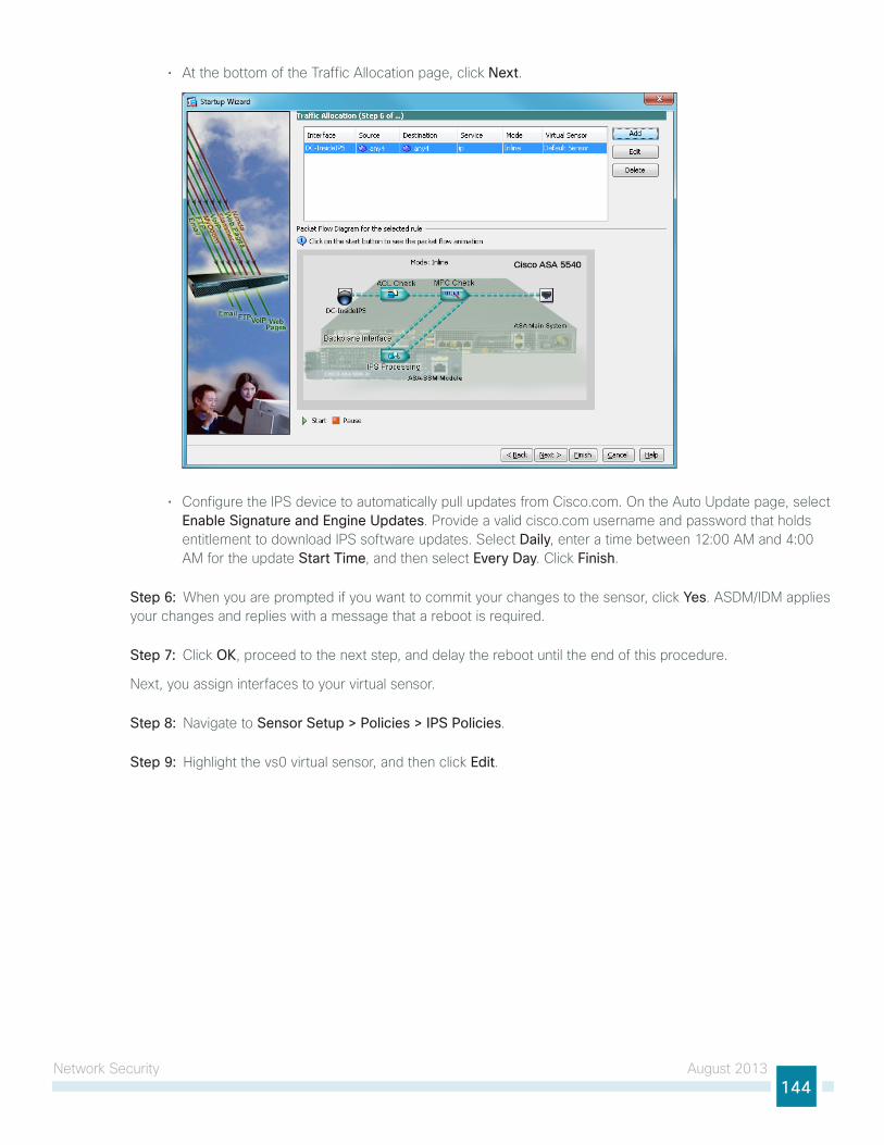
network security August 2013144
• At the bottom of the traffic Allocation page, click Next.
• Configure the iPs device to automatically pull updates from Cisco.com. on the Auto update page, select Enable Signature and Engine Updates. Provide a valid cisco.com username and password that holds entitlement to download iPs software updates. select Daily, enter a time between 12:00 AM and 4:00 AM for the update Start Time, and then select Every Day. Click Finish.
Step 6: When you are prompted if you want to commit your changes to the sensor, click Yes. AsDM/iDM applies your changes and replies with a message that a reboot is required.
Step 7: Click OK, proceed to the next step, and delay the reboot until the end of this procedure.
next, you assign interfaces to your virtual sensor.
Step 8: navigate to Sensor Setup > Policies > IPS Policies.
Step 9: highlight the vs0 virtual sensor, and then click Edit.
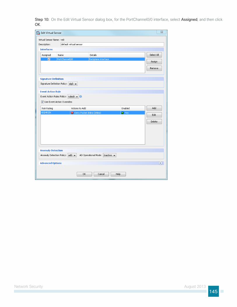
network security August 2013145
Step 10: on the edit Virtual sensor dialog box, for the PortChannel0/0 interface, select Assigned, and then click OK.
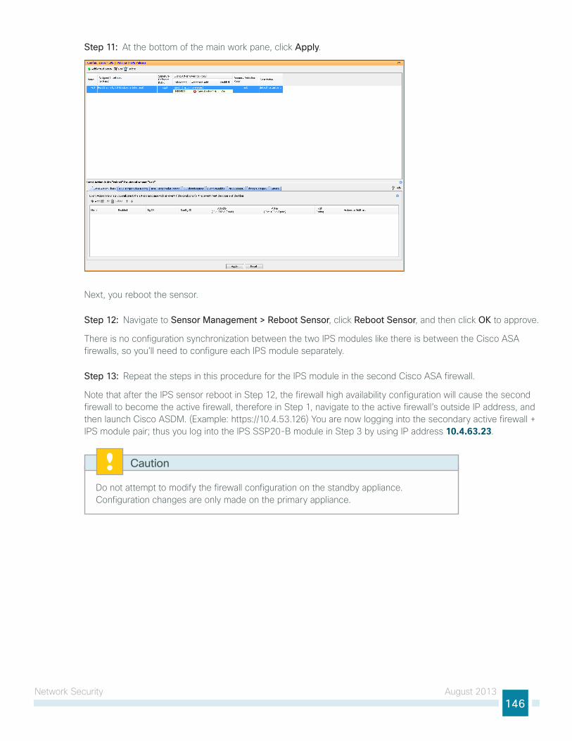
network security August 2013146
Step 11: At the bottom of the main work pane, click Apply.
next, you reboot the sensor.
Step 12: navigate to Sensor Management > Reboot Sensor, click Reboot Sensor, and then click OK to approve.
there is no configuration synchronization between the two iPs modules like there is between the Cisco AsA firewalls, so you’ll need to configure each iPs module separately.
Step 13: Repeat the steps in this procedure for the iPs module in the second Cisco AsA firewall.
note that after the iPs sensor reboot in step 12, the firewall high availability configuration will cause the second firewall to become the active firewall, therefore in step 1, navigate to the active firewall’s outside iP address, and then launch Cisco AsDM. (example: https://10.4.53.126) you are now logging into the secondary active firewall + iPs module pair; thus you log into the iPs ssP20-B module in step 3 by using iP address 10.4.63.23.
Do not attempt to modify the firewall configuration on the standby appliance. Configuration changes are only made on the primary appliance.
Caution
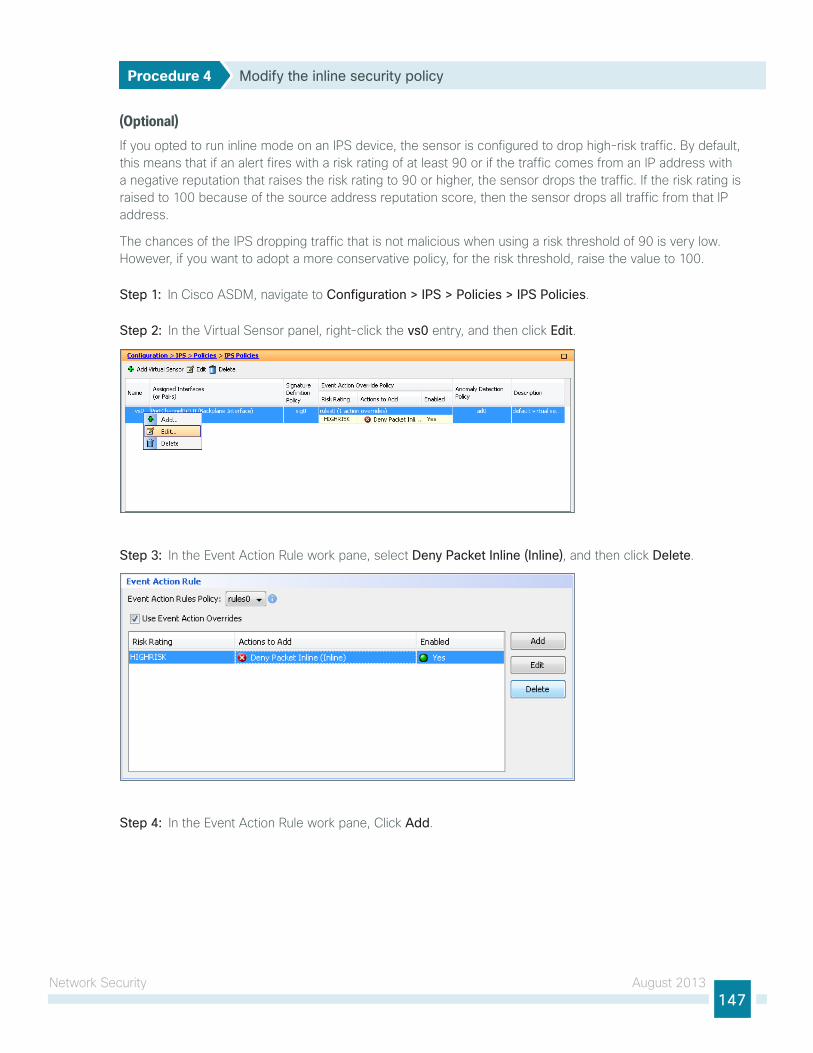
network security August 2013147
Procedure 4 Modify the inline security policy
(Optional)if you opted to run inline mode on an iPs device, the sensor is configured to drop high-risk traffic. By default, this means that if an alert fires with a risk rating of at least 90 or if the traffic comes from an iP address with a negative reputation that raises the risk rating to 90 or higher, the sensor drops the traffic. if the risk rating is raised to 100 because of the source address reputation score, then the sensor drops all traffic from that iP address.
the chances of the iPs dropping traffic that is not malicious when using a risk threshold of 90 is very low. however, if you want to adopt a more conservative policy, for the risk threshold, raise the value to 100.
Step 1: in Cisco AsDM, navigate to Configuration > IPS > Policies > IPS Policies.
Step 2: in the Virtual sensor panel, right-click the vs0 entry, and then click Edit.
Step 3: in the event Action Rule work pane, select Deny Packet Inline (Inline), and then click Delete.
Step 4: in the event Action Rule work pane, Click Add.
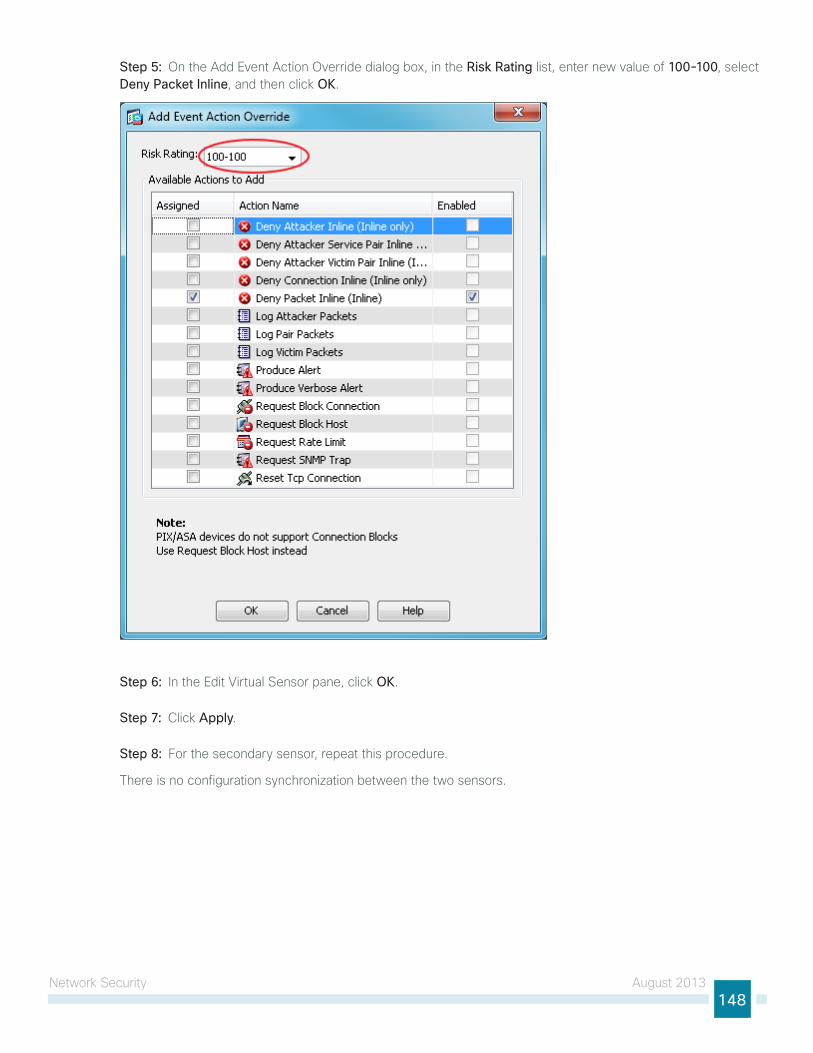
network security August 2013148
Step 5: on the Add event Action override dialog box, in the Risk Rating list, enter new value of 100-100, select Deny Packet Inline, and then click OK.
Step 6: in the edit Virtual sensor pane, click OK.
Step 7: Click Apply.
Step 8: For the secondary sensor, repeat this procedure.
there is no configuration synchronization between the two sensors.
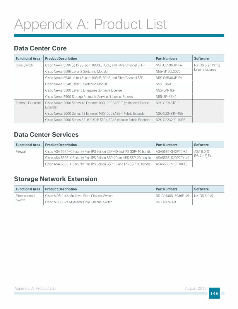
Appendix A: Product list August 2013149
Appendix A: Product listData Center Core
Functional Area Product Description Part Numbers Software
Core Switch Cisco Nexus 5596 up to 96-port 10GbE, FCoE, and Fibre Channel SFP+ N5K-C5596UP-FA NX-OS 5.2(1)N1(3) Layer 3 LicenseCisco Nexus 5596 Layer 3 Switching Module N55-M160L30V2
Cisco Nexus 5548 up to 48-port 10GbE, FCoE, and Fibre Channel SFP+ N5K-C5548UP-FA
Cisco Nexus 5548 Layer 3 Switching Module N55-D160L3
Cisco Nexus 5500 Layer 3 Enterprise Software License N55-LAN1K9
Cisco Nexus 5500 Storage Protocols Services License, 8 ports N55-8P-SSK9
Ethernet Extension Cisco Nexus 2000 Series 48 Ethernet 100/1000BASE-T (enhanced) Fabric Extender
N2K-C2248TP-E —
Cisco Nexus 2000 Series 48 Ethernet 100/1000BASE-T Fabric Extender N2K-C2248TP-1GE
Cisco Nexus 2000 Series 32 1/10 GbE SFP+, FCoE capable Fabric Extender N2K-C2232PP-10GE
Data Center ServicesFunctional Area Product Description Part Numbers Software
Firewall Cisco ASA 5585-X Security Plus IPS Edition SSP-40 and IPS SSP-40 bundle ASA5585-S40P40-K9 ASA 9.0(1) IPS 7.1(7) E4Cisco ASA 5585-X Security Plus IPS Edition SSP-20 and IPS SSP-20 bundle ASA5585-S20P20X-K9
Cisco ASA 5585-X Security Plus IPS Edition SSP-10 and IPS SSP-10 bundle ASA5585-S10P10XK9
Storage Network ExtensionFunctional Area Product Description Part Numbers Software
Fibre-channel Switch
Cisco MDS 9148 Multilayer Fibre Channel Switch DS-C9148D-8G16P-K9 NX-OS 5.0(8)
Cisco MDS 9124 Multilayer Fibre Channel Switch DS-C9124-K9
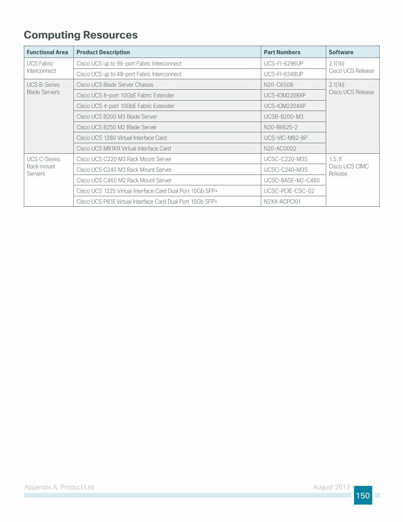
Appendix A: Product list August 2013150
Computing ResourcesFunctional Area Product Description Part Numbers Software
UCS Fabric Interconnect
Cisco UCS up to 96-port Fabric Interconnect UCS-FI-6296UP 2.1(1b) Cisco UCS ReleaseCisco UCS up to 48-port Fabric Interconnect UCS-FI-6248UP
UCS B-Series Blade Servers
Cisco UCS Blade Server Chassis N20-C6508 2.1(1b) Cisco UCS ReleaseCisco UCS 8-port 10GbE Fabric Extender UCS-IOM2208XP
Cisco UCS 4-port 10GbE Fabric Extender UCS-IOM2204XP
Cisco UCS B200 M3 Blade Server UCSB-B200-M3
Cisco UCS B250 M2 Blade Server N20-B6625-2
Cisco UCS 1280 Virtual Interface Card UCS-VIC-M82-8P
Cisco UCS M81KR Virtual Interface Card N20-AC0002
UCS C-Series Rack-mount Servers
Cisco UCS C220 M3 Rack Mount Server UCSC-C220-M3S 1.5.1f Cisco UCS CIMC Release
Cisco UCS C240 M3 Rack Mount Server UCSC-C240-M3S
Cisco UCS C460 M2 Rack Mount Server UCSC-BASE-M2-C460
Cisco UCS 1225 Virtual Interface Card Dual Port 10Gb SFP+ UCSC-PCIE-CSC-02
Cisco UCS P81E Virtual Interface Card Dual Port 10Gb SFP+ N2XX-ACPCI01
Appendix B: Device Configuration Files August 2013151
Appendix B: Device Configuration Files
to view the configuration files from the CVD lab devices that we used to test this guide, please go to the following uRl: http://cvddocs.com/fw/Rel2-505
Americas HeadquartersCisco Systems, Inc.San Jose, CA
Asia Pacific HeadquartersCisco Systems (USA) Pte. Ltd.Singapore
Europe HeadquartersCisco Systems International BV Amsterdam,The Netherlands
Cisco has more than 200 offices worldwide. Addresses, phone numbers, and fax numbers are listed on the Cisco Website at www.cisco.com/go/offices.
ALL DESIGNS, SPECIFICATIONS, STATEMENTS, INFORMATION, AND RECOMMENDATIONS (COLLECTIVELY, “DESIGNS”) IN THIS MANUAL ARE PRESENTED “AS IS,” WITH ALL FAULTS. CISCO AND ITS SUPPLIERS DISCLAIM ALL WARRANTIES, INCLUDING, WITHOUT LIMITATION, THE WARRANTY OF MERCHANTABILITY, FITNESS FOR A PARTICULAR PURPOSE AND NONINFRINGEMENT OR ARISING FROM A COURSE OF DEALING, USAGE, OR TRADE PRACTICE. IN NO EVENT SHALL CISCO OR ITS SUPPLIERS BE LIABLE FOR ANY INDIRECT, SPECIAL, CONSEQUENTIAL, OR INCIDENTAL DAMAGES, INCLUDING, WITHOUT LIMITATION, LOST PROFITS OR LOSS OR DAMAGE TO DATA ARISING OUT OF THE USE OR INABILITY TO USE THE DESIGNS, EVEN IF CISCO OR ITS SUPPLIERS HAVE BEEN ADVISED OF THE POSSIBILITY OF SUCH DAMAGES. THE DESIGNS ARE SUBJECT TO CHANGE WITHOUT NOTICE. USERS ARE SOLELY RESPONSIBLE FOR THEIR APPLICATION OF THE DESIGNS. THE DESIGNS DO NOT CONSTITUTE THE TECHNICAL OR OTHER PROFESSIONAL ADVICE OF CISCO, ITS SUPPLIERS OR PARTNERS. USERS SHOULD CONSULT THEIR OWN TECHNICAL ADVISORS BEFORE IMPLEMENTING THE DESIGNS. RESULTS MAY VARY DEPENDING ON FACTORS NOT TESTED BY CISCO.
Any Internet Protocol (IP) addresses used in this document are not intended to be actual addresses. Any examples, command display output, and figures included in the document are shown for illustrative purposes only. Any use of actual IP addresses in illustrative content is unintentional and coincidental.
© 2013 Cisco Systems, Inc. All rights reserved.
Cisco and the Cisco logo are trademarks or registered trademarks of Cisco and/or its affiliates in the U.S. and other countries. To view a list of Cisco trademarks, go to this URL: www.cisco.com/go/trademarks. Third-party trademarks mentioned are the property of their respective owners. The use of the word partner does not imply a partnership relationship between Cisco and any other company. (1110R)
Please use the feedback form to send comments and suggestions about this guide.
Feedback
B-0000515-1 08/13