Embed Size (px)
Citation preview

ACMD-7612
Miniature UMTS Band I Duplexer
Data Sheet
Description
The Avago ACMD-7612 is a miniature duplexer designed for use in UMTS Band I handsets.
Maximum Insertion Loss in the Tx channel is only 1.5 dB, which minimizes current drain from the power ampli�er. Insertion Loss in the Rx channel is a maximum of 2.0 dB, improving receiver sensitivity.
The ACMD-7612 enhances the sensitivity and dynamic range of WCDMA receivers by providing more than 53 dB attenuation of the transmitted signal at the receiver input and more than 43 dB rejection of trans-mit-generated noise in the receive band.
The ACMD-7612 is designed with Avago Technologies’ Film Bulk Acoustic Resonator (FBAR) technology, which makes possible ultra-small, high-Q �lters at a fraction of their usual size. The excellent power handling capabil-ity of the FBAR bulk-mode resonators supports the high output power levels needed in handsets while adding virtually no distortion.
The ACMD-7612 also utilizes Avago Technologies’ in-novative Microcap bonded-wafer, chip scale packaging technology. This process allows the �lters to be assem-bled in a molded chip-on-board module that is less than 1.2 mm high with a maximum footprint of only 2.5 mm x 3.0 mm.
Features
• Miniature size - 2.5 x 3.0 mm max footprint - 1.2 mm max height
• High power rating - +33 dBm Abs Max Tx Power
• Lead-free construction
Speci!cations
• Performance guaranteed –30 to +85°C
• Rx band performance (2110 – 2170 mHz) - Insertion loss: 2.0 dB max - Noise blocking: 43 dB min
• Tx band performance (1920 – 1980 mHz) - Insertion loss: 1.5 dB max - Interferer blocking: 53 dB min
Applications
• Handsets or data terminals operating in the UMTS Band I frequency range
Functional Block Diagram
ANTPORT 3
RxPORT 2
TxPORT 1

2
ACMD-7612 Speci!cations, Z0 = 50 Ω, TC[1] as Indicated
–30 to +85°C[2]
Symbol Parameter Units Min Typ[3] Max
Antenna Port to Receive Port
S23 Insertion Loss in Receive Band (2110 – 2170 MHz) dB 1.1 2.0
∆S23 Ripple (p-p) in Receive Band dB 0.6 1.0
∆S23 Ripple (p-p) in Any 5 MHz Channel within Receive Band dB – 0.5
S22 Return Loss of Receive Port in Receive Band dB 10 16
S23 Attenuation 0 – 1900 mHz dB 30 50
S23 Attenuation in Transmit Band (1920 – 1980 mHz) dB 53 61
S23 Attenuation in Bluetooth Band (2400 – 2500 mHz) dB 40 54
Transmit Port to Antenna Port
S31 Insertion Loss in Transmit Band (1920 – 1980 mHz) -30° to +25°C dB 1.1 1.5
S31 Insertion Loss in Transmit Band (1920 – 1980 mHz) +25° to +85°C dB 1.1 1.6
∆S31 Ripple (p-p) in Transmit Band dB 0.4 1.0
∆S31 Ripple (p-p) in Any 5 mHz Channel within Transmit Band dB – 0.5
S11 Return Loss of Transmit Port in Transmit Band dB 10 20
S31 Attenuation 0 – 1800 mHz dB 30 44
S31 Attenuation in Receive Band (2110 – 2170 mHz) dB 41 52
S31 Attenuation in Bluetooth Band (2400 – 2500 mHz) dB 25 31
S31 Attenuation in Transmit 2nd Harmonic Band (3840 – 3960 mHz) dB 25 36
S31 Attenuation in Transmit 3rd Harmonic Band (5760 – 5940 mHz) dB 15 17
Antenna Port
S33 Return Loss of Antenna Port in Transmit and Receive Bands dB 10 17
Isolation Transmit Port to Receive Port
S21 Tx-Rx Isolation in Transmit Band (1920 – 1980 mHz) dB 53 62
S21 Tx-Rx Isolation in Receive Band (2110 – 2170 mHz) dB 43 52
Notes:
1. TC is the case temperature and is de�ned as the temperature of the underside of the duplexer where it makes contact with the circuit board.
2. Speci�cations guaranteed over the given temperature range (unless otherwise noted) with the input power to the Tx port equal to or less than
+29 dBm over all Tx frequencies.
3. Typical data is the arithmetic mean value of the parameter over its indicated frequency range at the speci�ed temperature. Typical values may
vary from part to part and over time.

3
Absolute Maximum Ratings[1]
Parameter Unit Value
Storage Temperature °C -65 to +125
Maximum RF Input Power to Tx Port dBm +33
Maximum Recommended Operating Conditions[2]
Parameter Unit Value
Operating Temperature, TC[3] , Tx Power ≤ 29 dBm °C -40 to +100
Operating Temperature, TC[3] , Tx Power ≤ 30 dBm °C -40 to +85 Notes:1. Operation in excess of any one of these conditions may result in permanent damage to the device. 2. The device will function over the recommended range without degradation in reliability or permanent change in performance, but is not
guaranteed to meet electrical speci�cations.3. TC is de�ned as case temperature, the temperature of the underside of the duplexer where it makes contact with the circuit board.
Figure 2. Rx band insertion lossFigure 1. Tx band insertion loss
ACMD-7612 Typical Performance at TC = 25°C
Figure 3. Tx and Rx port return loss Figure 4. Tx rejection in Rx band and Rx rejection in Tx band
0
-0.5
-1.0
-1.5
-2.0
-2.51920 1930 1940 1950 1960 19801970
FREQUENCY (MHz)
INS
ER
TIO
N L
OS
S (
dB
)
0
-0.5
-1.0
-1.5
-2.0
-2.52110 2120 2130 2140 2150 21702160
FREQUENCY (MHz)
INS
ER
TIO
N L
OS
S (
dB
)
0
-5
-10
-15
-20
-251800 1900
Tx Rx
2000 2100 2200 2300
FREQUENCY (MHz)
RE
TU
RN
LO
SS
(d
B)
0
-10
-30
-50
-20
-40
-601800 1900
Tx Rx
2000 2100 2200 2300
FREQUENCY (MHz)
INS
ER
TIO
N L
OS
S (
dB
)

4
Figure 5. Tx to Rx isolation
Figure 10. Rx rejection in bluetooth band (2400 – 2500 mHz)Figure 9. Tx rejection in bluetooth band (2400 – 2500 mHz)
Figure 8. Tx third harmonic rejectionFigure 7. Tx second harmonic rejection
Figure 6. Antenna port return loss
-40
-50
-60
-70
-801800 1900 2000 2100 2200 2300
FREQUENCY (MHz)
INS
ER
TIO
N L
OS
S (
dB
)0
-5
-10
-15
-20
-251800 1900 2000 2100 2200 2300
FREQUENCY (MHz)
RE
TU
RN
LO
SS
(d
B)
-20
-30
-40
-50
-603.80 3.85 3.90 3.95 4.00
FREQUENCY (GHz)
INS
ER
TIO
N L
OS
S (
dB
)
0
-10
-20
-30
-405.7 5.8 5.8 5.95.9 6.0 6.0
FREQUENCY (GHz)
INS
ER
TIO
N L
OS
S (
dB
)
-20
-30
-40
-502.40 2.42 2.462.44 2.48 2.50
FREQUENCY (GHz)
INS
ER
TIO
N L
OS
S (
dB
)
-40
-50
-60
-702.40 2.42 2.462.44 2.48 2.50
FREQUENCY (GHz)
INS
ER
TIO
N L
OS
S (
dB
)

5
Figure 13. Tx and Rx wideband response
Figure 12. Rx low frequency rejectionFigure 11. Tx low frequency rejection
-20
-30
-50
-70
-40
-60
-800 0.2 0.4 0.6 0.8 1.0 1.2 1.4 1.6 1.8
FREQUENCY (GHz)
INS
ER
TIO
N L
OS
S (
dB
)-20
-30
-50
-70
-40
-60
-800 0.2 0.4 0.6 0.8 1.0 1.2 1.4 1.6 2.01.8
FREQUENCY (GHz)
INS
ER
TIO
N L
OS
S (
dB
)
0
-10
-30
-50
-20
-40
-600 1
Tx
Tx
Rx
Rx
2 3 4 5 6
FREQUENCY (MHz)
INS
ER
TIO
N L
OS
S (
dB
)

6
Figure 14. Tx impedance (S11) in Tx band
Figure 16. Ant impedance (S33) in Tx band
Figure 15. Rx impedance (S22) in Rx band
Figure 17. Ant impedance (S33) in Rx band
0.4
-0.4
0.6
-0.6
0.8
-0.8
1.0
-1.0
1.5
-1.5
2
-2
3
-3
4
-4
5
-5
10
-10
20
-20
50
-500.40.2 0.6 0.8 1.0 1.5 2 3 4 5 10 20 50
0.4
-0.4
0.6
-0.6
0.8
-0.8
1.0
-1.0
1.5
-1.5
2
-2
3
-3
4
-4
5
-5
10
-10
20
-20
50
-500.40.2 0.6 0.8 1.0 1.5 2 3 4 5 10 20 50
0.4
-0.4
0.6
-0.6
0.8
-0.8
1.0
-1.0
1.5
-1.5
2
-2
3
-3
4
-4
5
-5
10
-10
20
-20
50
-500.40.2 0.6 0.8 1.0 1.5 2 3 4 5 10 20 50
0.4
-0.4
0.6
-0.6
0.8
-0.8
1.0
-1.0
1.5
-1.5
2
-2
3
-3
4
-4
5
-5
10
-10
20
-20
50
-500.40.2 0.6 0.8 1.0 1.5 2 3 4 5 10 20 50

7
Figure 18. Package drawing
Figure 19. Package marking
ANT
P
PACKAGEORIENTATION
TXRXP = ACMD-7612
FB = Avago ID
Y = Year
WW = Work Week
DC = Date Code
NNNN = Lot Number
PRODUCT
MARKING
PACKAGEORIENTATION
ANT
RxTx
Notes:1. Dimensions in millimeters2. nominal unless otherwise noted 34
5. Tolerance: X.X = ± 0.1 X.XX = ±0.056. Contact areas are gold plated
Dimensions . All chamfers 45°. I/O pads (3 ea)
Size: 0.53 x 0.53, corner chamfers: 0.03 x 0.03 Spacing to ground plane: 0.34 Inside ground plane chamfer: 0.20 x 0.20
3.0MAX
2.5
MA
X
2.80
2.3
0
2.27
1.2MAX
0.53
0.34
0.53
0.53
0.34
0.20
0.53
0.34
0.340.53
0.34
0.34
0.20

8
Figure 20. PCB layout
A PCB layout implementing design principles similar to those illustrated in Figure 16 is recommended to optimize performance of the ACMD-7612.
It is particularly important to maximize isolation between the Tx connection to the duplexer and the Rx port. High isolation is achieved by (1) maintaining a continuous ground plane around the duplexer mounting area, (2) surrounding the I/O ports with su$cient ground vias to enclose the connections in a “Faraday cage”, and (3) preferably routing the Tx trace in a di%erent metal layer than the Rx.
The latter is especially useful, not only to maintain Tx-Rx isolation of the duplexer, but also to prevent leakage of the Tx signal into other components that could result in the creation of intermodulation products and degradation of overall system performance. Figure 21. ACMD-7612 superposed on PCB layout
Ant
R x
Tx
2.27
1.78
G
W
Ø 0.20 VIA ARRAY
HORIZ PITCH = 0.33
VERT PITCH = 0.38
Ø 0.20 VIA ARRAY
HORIZ PITCH = 0.38
Notes:
1. Dimensions in mm.
2. Transmission line Gap (G) and Width (W) adjusted for Zo = 50 ohms.
3. I/O Pads (3 ea) 0.53 x 0.53, corner chamfer 0.30.
4. I/O Pad to Ground plane gap = 0.34, corner chamfer 0.30.
5. Ground vias positioned to maximize port-to-port isolation.
VERT PITCH = 0.33
Ø 0.20 VIA ARRAY
HORIZ PITCH = 0.38
Ø 0.20 VIA ARRAY
HORIZ PITCH = 0.33
VERT PITCH = 0.38
0.10
0.10

9
Figure 22. Recommended solder mask
Figure 25. Solder stencil overlaid on ACMD-7612 bottom metal pattern
Figure 24. Recommended solder stencil
Figure 23. ACMD-7612 superposed on solder mask
2.90
2.40
> 0.30 TYP.
> 0.30 TYP.
0.24
0.63
0.63
0.24
Note:
Dimensions in mm.
A
C
B
A
A
B
2.80
2.30
STENCIL
BOUNDARY
0.15 0.15
STENCIL OPENING ID QTY WIDTH (mm) LENGTH (mm)
C 1 0.77 1.24
B 2 0.50 1.24
A (I/O pad areas) 3 0.43 0.43
Notes:1. Chamfer or radius all corners 0.05 mm min.2. Stencil openings aligned to Boundary rectangle or center lines.

10
Figure 26. SMD tape packing
Figure 27. Unit orientation in tape
SECTION B – B
SECTION A – A
R0.60 TYP.
5 (MAX.)
Ko
Bo
Ao
1.50 (MIN.)
1.55 0.052.00 0.05
12.00 0.10
5.50 0.05
1.75 0.10
4.00 0.10(SEE NOTE #2)
8.00 0.10
NOTES:
1. Ao and Bo measured at 0.3 mm above base of pocket.
2. 10 pitches cumulative tolerance 0.2 mm.
3. ( ) Reference dimensions only.
Ao = 2.80
Bo = 3.30
Ko = 1.50
Pitch = 8.00
Width = 12.00
0.30 0.05
SPROCKET HOLES
TAPEWIDTH
POCKETCAVITY
PACKAGE PIN 1ORIENTATION
P P P
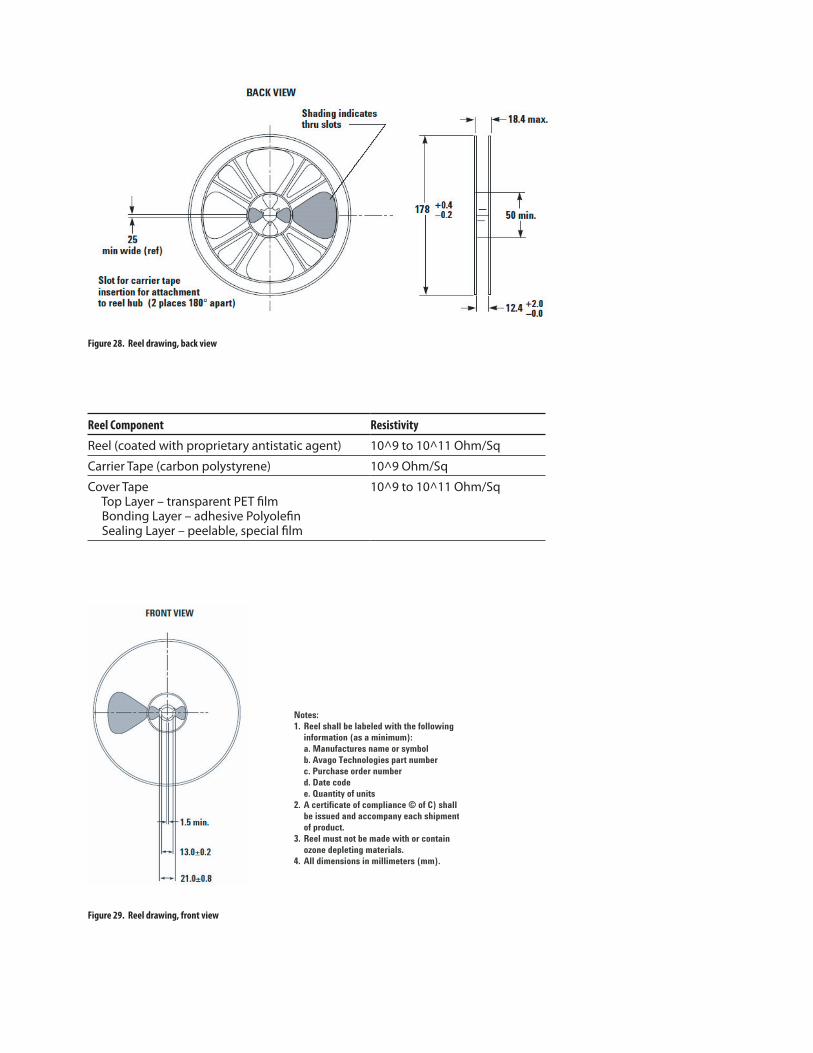
Figure 29. Reel drawing, front view
Figure 28. Reel drawing, back view
Reel Component Resistivity
Reel (coated with proprietary antistatic agent) 10^9 to 10^11 Ohm/Sq
Carrier Tape (carbon polystyrene) 10^9 Ohm/Sq
Cover Tape Top Layer – transparent PET �lm Bonding Layer – adhesive Polyole�n Sealing Layer – peelable, special �lm
10^9 to 10^11 Ohm/Sq
Notes:
1. Reel shall be labeled with the following
information (as a minimum):
a. Manufactures name or symbol
b. Avago Technologies part number
c. Purchase order number
d. Date code
e. Quantity of units
2. A certificate of compliance © of C) shall
be issued and accompany each shipment
of product.
3. Reel must not be made with or contain
ozone depleting materials.
4. All dimensions in millimeters (mm).

Package Moisture Sensitivity
Feature Test Method Performance
Moisture Sensitivity Level (MSL) at 260°C
J-STD-020C Level 3
Figure 30. Veri!ed SMT solder pro!le
ACMD-7612 Ordering Information
Part Number No. of Devices Container
ACMD-7612-BLK 25 Anti-static Bag
ACMD-7612-TR1 1000 178 mm (7-inch) Reel
For product information and a complete list of distributors, please go to our website: www.avagotech.com
Avago, Avago Technologies, and the A logo are trademarks of Avago Technologies Limited in the United States and other countries.
Data subject to change. Copyright © 2007 Avago Technologies Limited. All rights reserved.
AV02-0473EN - September 25, 2007
300
250
150
50
200
100
00 50 100 150 200 250 300
TIME (SECONDS)
TE
MP
ER
TU
RE
(C
)
Tested profile shown.