Embed Size (px)
Citation preview
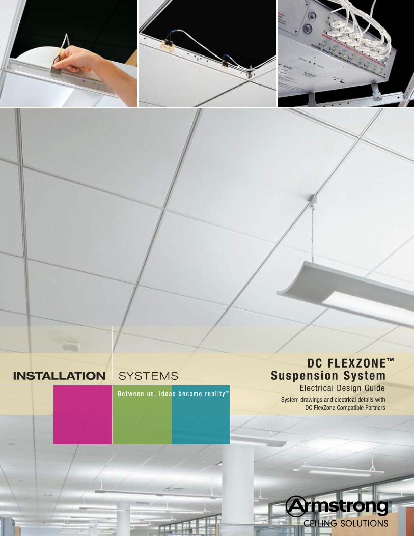
B e t w e e n u s , i d e a s b e c o m e r e a l i t y ™
InstallatIon SYSTEMSDC FlexZone ™
Suspension System Electrical Design Guide
System drawings and electrical details withDC FlexZone Compatible Partners
1
Room Level Power Distribution Standard
Controls
Power Infrastructure Devices
Room Level Power Distribution Standard
Controls
Power Infrastructure Devices
Room Level Power Distribution Standard
Controls
Power Infrastructure Devices
AC Branch Power
Optional On-SiteDC Power
Multi-Source PowerSupplies to 24 VDC
Structured Cabling& Interconnects
Powered Bus Bar Components (i.e., Ceiling
Suspension System)
Device Cabling& Interconnects
Lights, Sensors, AV, IT,Actuators, etc.
Room Level Power Distribution Standard
Controls
Power Infrastructure DevicesVisit emergealliance.org for more information on their platform of DC power distribution standards.
Room Level Power Distribution Standard
Controls
Power Infrastructure Devices
Copyright EMerge Alliance. All rights reserved.
eMerge Alliance Registered® & Related Product Categories(for Building Applications of EMerge 24VDC Occupied Space Standard)
Specified by elect. engineer / lighting Designer(Div 16/26)
Purchased by electrical Contractor
Installed by electrical Contractor
Specified by Architect / Interior Designer(Div 9)
Purchased by Acoustical Contractor
Installed by Acoustical Contractor
9/16" Ceiling Suspension System(Armstrong DC FlexZone™ – Suprafine Exposed Tee or Silhouette 1/4" Slot Reveal)
• • •
Acoustical Ceiling Tile(i.e. Armstrong Ultima® 1912HRC) • • •AC-DC Power Supplies, DC-DC Power Supplies • • •Power Feed Cables • • •24VDC lighting FixturesLED or Fluorescent with Connectors and / or Load Device Cable Assemblies
• • •
24VDC Ballasts or Drivers for lighting Fixtures • • •Controls (Wireless or Wired) • • •
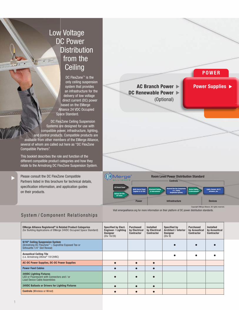
Low Voltage DC Power
Distribution from the CeilingDC FlexZone™ is the only ceiling suspension system that provides an infrastructure for the
delivery of low voltage direct current (DC) power
based on the EMerge Alliance 24 VDC Occupied
Space Standard.
DC FlexZone Ceiling Suspension Systems are designed for use with
compatible power, infrastructure, lighting, and control products. Compatible products are
available from other members of the EMerge Alliance, several of whom are called out here as “DC FlexZone Compatible Partners”.
This booklet describes the role and function of the different compatible product categories and how they relate to the Armstrong DC FlexZone Suspension System.
Please consult the DC FlexZone Compatible Partners listed in this brochure for technical details, specification information, and application guides on their products.
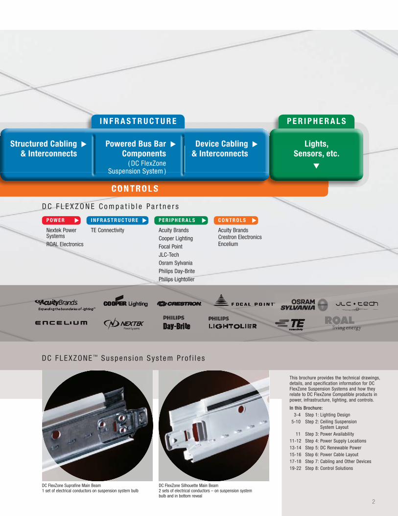
S y s t em / Componen t Re l a t i onsh i p s
▲
P o W e R
C o n T R o l S
Power Supplies Structured Cabling& Interconnects
AC Branch Power DC Renewable Power
(Optional)
▲ ▲
▲ ▲
▲
2
This brochure provides the technical drawings, details, and specification information for DC FlexZone Suspension Systems and how they relate to DC FlexZone Compatible products in power, infrastructure, lighting, and controls.
In this Brochure:3-4 Step 1: Lighting Design
5-10 Step 2: Ceiling Suspension System Layout
11 Step 3: Power Availability 11-12 Step 4: Power Supply Locations 13-14 Step 5: DC Renewable Power 15-16 Step 6: Power Cable Layout 17-18 Step 7: Cabling and Other Devices 19-22 Step 8: Control Solutions
DC FlexZone Suprafine Main Beam 1 set of electrical conductors on suspension system bulb
DC FlexZone Silhouette Main Beam 2 sets of electrical conductors – on suspension system bulb and in bottom reveal
DC FLEXZONE ™ Suspens i on Sys t em P ro f i l e s
Copyright EMerge Alliance. All rights reserved.
Nextek Power SystemsROAL Electronics
D C F L E X Z O N E C o m p a t i b l e P a r t n e r s
TE Connectivity Acuity BrandsCooper LightingFocal PointJLC-TechOsram SylvaniaPhilips Day-BritePhilips Lightolier
Acuity BrandsCrestron ElectronicsEncelium
P o W e R
▲
I n F R A S T R u C T u R e
▲
P e R I P h e R A l S
▲
C o n T R o l S
▲
C o n T R o l S
I n F R A S T R u C T u R e P e R I P h e R A l S
C o n T R o l S
Structured Cabling& Interconnects
lights, Sensors, etc.
Device Cabling& Interconnects
Powered Bus BarComponents
( DC FlexZone Suspension System )
▲ ▲▲
▲
▲
3
P O W E R
AC Branch PowerAC Branch PowerDC Renewable Power
(Optional)
▲ ▲
▲ ▲
▲ ▲
▲ ▲
▲ ▲
▲ ▲
Power Power Power Supplies
▲▲▲
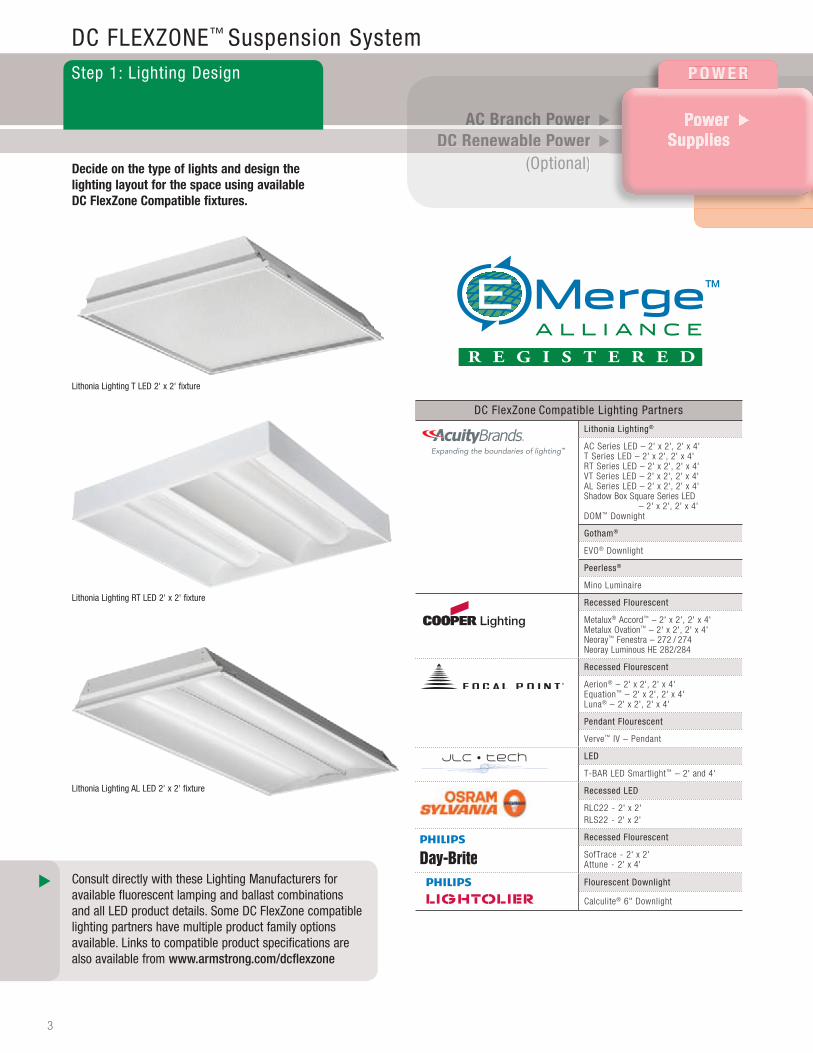
DC FLEXZONE™ Suspension SystemStep 1: Lighting Design
Consult directly with these Lighting Manufacturers for available fluorescent lamping and ballast combinations and all LED product details. Some DC FlexZone compatible lighting partners have multiple product family options available. Links to compatible product specifications are also available from www.armstrong.com/dcflexzone
Decide on the type of lights and design the lighting layout for the space using available DC FlexZone Compatible fixtures.
Lithonia Lighting AL LED 2' x 2' fixture
Lithonia Lighting RT LED 2' x 2' fixture
Lithonia Lighting T LED 2' x 2' fixture
DC FlexZone Compatible Lighting Partners
Lithonia Lighting®
AC Series LED – 2' x 2', 2' x 4'T Series LED – 2' x 2', 2' x 4'RT Series LED – 2' x 2', 2' x 4'VT Series LED – 2' x 2', 2' x 4'AL Series LED – 2' x 2', 2' x 4' Shadow Box Sq uare Series LED
– 2' x 2', 2' x 4'DOM™ Downight
Gotham®
EVO® Downlight
Peerless®
Mino Luminaire
Recessed Flourescent
Metalux® Accord™ – 2' x 2', 2' x 4' Metalux Ovation™ – 2' x 2', 2' x 4' Neoray™ Fenestra – 272 / 274 Neoray Luminous HE 282/284
Recessed Flourescent
Aerion® – 2' x 2', 2' x 4' Equation™ – 2' x 2', 2' x 4' Luna® – 2' x 2', 2' x 4'
Pendant Flourescent
Verve™ IV – Pendant
LED
T-BAR LED Smartlight™ – 2' and 4'
Recessed LED
RLC22 - 2' x 2' RLS22 - 2' x 2'
Recessed Flourescent
SofTrace - 2' x 2' Attune - 2' x 4'
Flourescent Downlight
Calculite® 6" Downlight

2' x 2' Light Fixture
4
OSRAM RLC22
OSRAM RLS22
2' T-BAR LED Smartlight™ 4' T-BAR LED Smartlight4' Linear Pendant
P e R I P h e R A l SI N F R A S T R U C T U R E
C O N T R O L SC O N T R O L S
lights, Sensors, etc.
▲
Structured Structured Cabling &
Interconnects
Device CablingDevice Cabling& Interconnects
Powered Bus BarPowered Bus BarPowered Bus BarComponents
( DC FlexZoneSuspension System )Suspension System )
▲▲▲ ▲▲▲▲▲
Focal Point Verve™ IV pendant lighting fixtures
Cooper NeoRay™ Luminous HE lighting fixture.
JLC-Tech T-BAR LED Smartlight
P O W E R
AC Branch PowerAC Branch PowerDC Renewable Power
(Optional)
▲ ▲
▲ ▲
▲ ▲
▲ ▲
▲ ▲
▲ ▲
Power Power Power Supplies
▲▲▲
600Watts
1200Watts
6'
8'
10'
12'
6'
6'
8'
10'
12'
6'
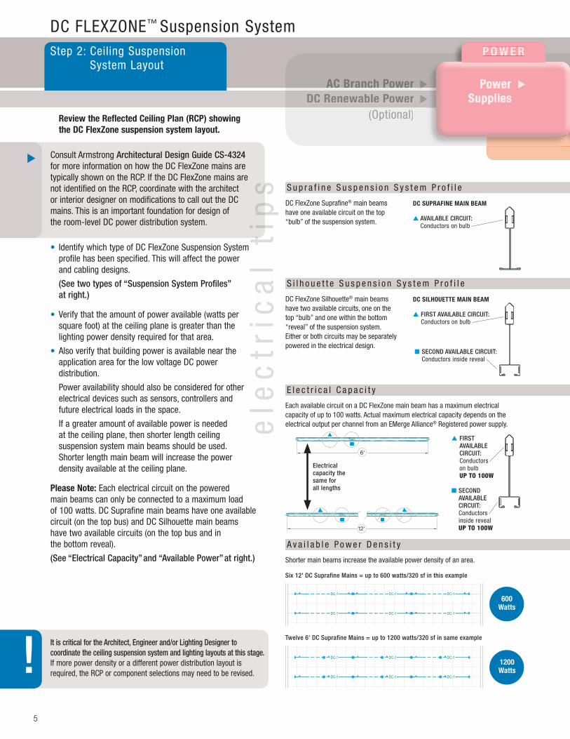
DC FLEXZONE™ Suspension SystemStep 2: Ceiling Suspension
System Layout
Review the Reflected Ceiling Plan (RCP) showing the DC FlexZone suspension system layout.
Consult Armstrong Architectural Design Guide CS-4324 for more information on how the DC FlexZone mains are typically shown on the RCP. If the DC FlexZone mains are not identified on the RCP, coordinate with the architect or interior designer on modifications to call out the DC mains. This is an important foundation for design of the room-level DC power distribution system.
• Identify which type of DC FlexZone Suspension System profile has been specified. This will affect the power and cabling designs.
(See two types of “Suspension System Profiles”at right.)
• Verify that the amount of power available (watts per square foot) at the ceiling plane is greater than thelighting power density required for that area.
• Also verify that building power is available near theapplication area for the low voltage DC powerdistribution.
Power availability should also be considered for other electrical devices such as sensors, controllers andfuture electrical loads in the space.
If a greater amount of available power is neededat the ceiling plane, then shorter length ceilingsuspension system main beams should be used.Shorter length main beam will increase the powerdensity available at the ceiling plane.
Please note: Each electrical circuit on the powered main beams can only be connected to a maximum load of 100 watts. DC Suprafine main beams have one available circuit (on the top bus) and DC Silhouette main beams have two available circuits (on the top bus and in the bottom reveal).
(See “Electrical Capacity” and “Available Power” at right.)
It is critical for the Architect, Engineer and/or Lighting Designer to coordinate the ceiling suspension system and lighting layouts at this stage. If more power density or a different power distribution layout is required, the RCP or component selections may need to be revised.
DC SuPRAFIne MAIn BeAM
▲ AVAILABLE CIRCUIT: Conductors on bulb
DC FlexZone Suprafine® main beams have one available circuit on the top “bulb” of the suspension system.
S u p r a f i n e S u s p e n s i o n S y s t e m P r o f i l e
DC SIlhoueTTe MAIn BeAM
▲ FIRST AVAILABLE CIRCUIT: Conductors on bulb
■ SECOND AVAILABLE CIRCUIT: Conductors inside reveal
DC FlexZone Silhouette® main beams have two available circuits, one on the top “bulb” and one within the bottom “reveal” of the suspension system. Either or both circuits may be separately powered in the electrical design.
S i l h o u e t t e S u s p e n s i o n S y s t e m P r o f i l e
A v a i l a b l e P o w e r D e n s i t y
Shorter main beams increase the available power density of an area.
Six 12' DC Suprafine Mains = up to 600 watts/320 sf in this example
Twelve 6' DC Suprafine Mains = up to 1200 watts/320 sf in same example
ele
ctr
ica
l ti
ps
ele
ctr
ica
l ti
ps
Each available circuit on a DC FlexZone main beam has a maximum electrical capacity of up to 100 watts. Actual maximum electrical capacity depends on theelectrical output per channel from an EMerge Alliance® Registered power supply.
E l e c t r i c a l C a p a c i t y
Electrical capacity the same for all lengths
▲ FIRST AVAILABLE CIRCUIT: Conductors on bulb UP TO 100W
■ SECOND AVAILABLE CIRCUIT: Conductors inside reveal UP TO 100W
55
!
▲
I n F R A S T R u C T u R e P E R I P H E R A L S
C O N T R O L S
Lights, Lights, Lights, Sensors, etc.
▲
Device CablingDevice Cabling& Interconnects
▲▲
Structured Structured Cabling &
Interconnects
▲▲▲
C O N T R O L S
▲▲▲
Powered Bus BarComponents
( DC FlexZone Suspension System )
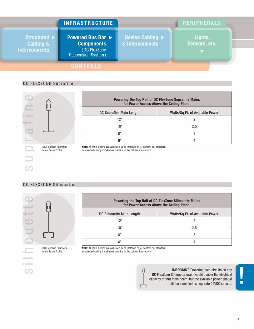
▲DC FlexZone Suprafine Main Beam Profile
DC FlexZone Silhouette Main Beam Profile
D C F L E X Z O N E S i l h o u e t t e
D C F L E X Z O N E S u p r a f i n e
Powering the Top Rail of DC FlexZone Suprafine Mains
for Power Access Above the Ceiling Plane:
DC Suprafine Main Length Watts/Sq Ft. of Available Power
12' 2
10' 2.5
8' 3
6' 4
Powering the Top Rail of DC FlexZone Silhouette Mains
for Power Access Above the Ceiling Plane:
DC Silhouette Main Length Watts/Sq Ft. of Available Power
12' 2
10' 2.5
8' 3
6' 4
sil
ho
ue
tte
sil
ho
ue
tte
sil
ho
ue
tte
su
pra
fin
es
up
rafi
ne
su
pra
fin
e
note: All main beams are assumed to be installed on 4' centers per standard suspended ceiling installation practice in the calculations above.
note: All main beams are assumed to be installed on 4' centers per standard suspended ceiling installation practice in the calculations above.
IMPORTANT: Powering both circuits on any DC FlexZone Silhouette main would double the electrical
capacity of that main beam, but the available power should still be identified as separate 24VDC circuits.
66
!
P O W E R
AC Branch PowerAC Branch PowerDC Renewable Power
(Optional)
▲ ▲
▲ ▲
▲ ▲
▲ ▲
▲ ▲
▲ ▲
Power Power Power Supplies
▲▲▲
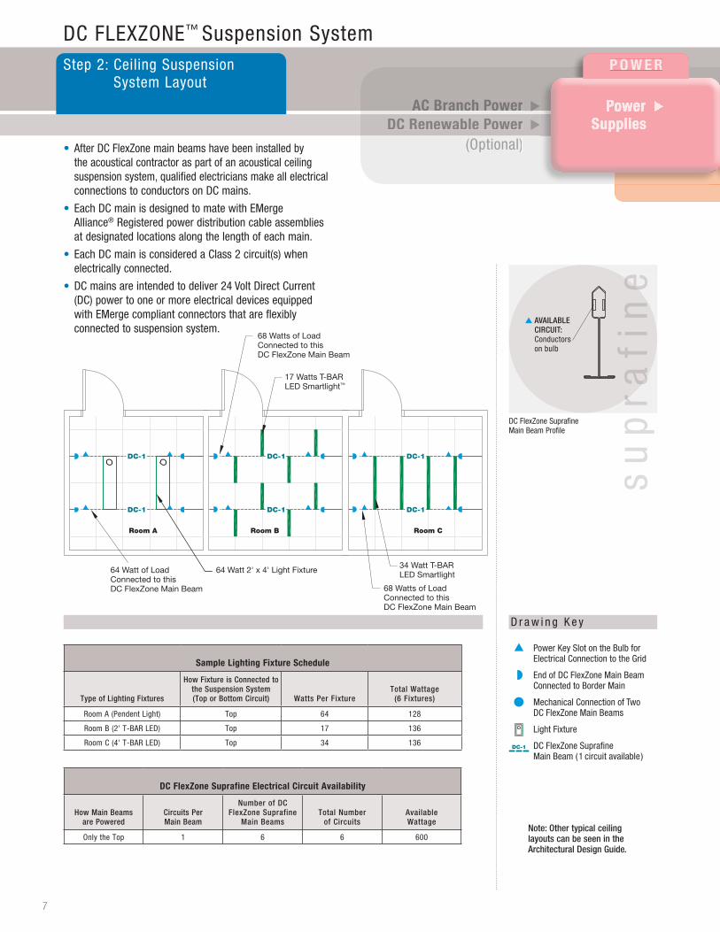
64 Watt of LoadConnected to this DC FlexZone Main Beam
64 Watt 2' x 4' Light Fixture
68 Watts of LoadConnected to this DC FlexZone Main Beam
17 Watts T-BAR LED Smartlight™
34 Watt T-BAR LED Smartlight
68 Watts of LoadConnected to this DC FlexZone Main Beam
DC-1DC-1DC-1
DC-1DC-1DC-1
Room A Room B Room C
DC FLEXZONE™ Suspension SystemStep 2: Ceiling Suspension
System Layout
Sample lighting Fixture Schedule
Type of Lighting Fixtures
How Fixture is Connected to the Suspension System (Top or Bottom Circuit) Watts Per Fixture
Total Wattage (6 Fixtures)
Room A (Pendent Light) Top 64 128
Room B (2' T-BAR LED) Top 17 136
Room C (4' T-BAR LED) Top 34 136
DC FlexZone Suprafine electrical Circuit Availability
How Main Beams are Powered
Circuits Per Main Beam
Number of DC FlexZone Suprafine
Main BeamsTotal Number
of CircuitsAvailable Wattage
Only the Top 1 6 6 600
• After DC FlexZone main beams have been installed by the acoustical contractor as part of an acoustical ceiling suspension system, qualified electricians make all electrical connections to conductors on DC mains.
• Each DC main is designed to mate with EMerge Alliance® Registered power distribution cable assemblies at designated locations along the length of each main.
• Each DC main is considered a Class 2 circuit(s) when electrically connected.
• DC mains are intended to deliver 24 Volt Direct Current (DC) power to one or more electrical devices equipped with EMerge compliant connectors that are flexibly connected to suspension system.
D r a w i n g K e y
Note: Other typical ceiling layouts can be seen in the Architectural Design Guide.
DC FlexZone Suprafine Main Beam Profile
▲ AVAILABLE CIRCUIT: Conductors on bulb
Power Key Slot on the Bulb for Electrical Connection to the Grid
End of DC FlexZone Main BeamConnected to Border Main
Mechanical Connection of TwoDC FlexZone Main Beams
Light Fixture
DC FlexZone Supra�ne Main Beam (1 circuit available)
DC-1
7
su
pra
fin
es
up
rafi
ne
su
pra
fin
e
I n F R A S T R u C T u R e P E R I P H E R A L S
C O N T R O L S
Lights, Lights, Lights, Sensors, etc.
▲
Device CablingDevice Cabling& Interconnects
▲▲
Structured Structured Cabling &
InterconnectsInterconnects
▲▲▲
C O N T R O L S
▲▲▲
Powered Bus BarComponents
( DC FlexZone Suspension System )
▲
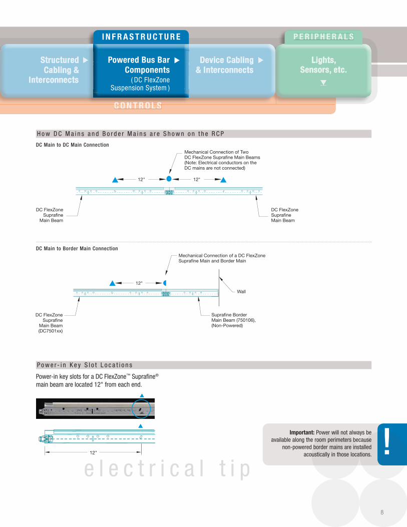
Mechanical Connection of Two DC FlexZone Supra�ne Main Beams(Note: Electrical conductors on the DC mains are not connected)
DC FlexZoneSupra�ne
Main Beam
DC FlexZoneSupra�neMain Beam
12" 12"
Wall
Mechanical Connection of a DC FlexZone Supra�ne Main and Border Main
DC FlexZoneSupra�ne
Main Beam(DC7501xx)
Supra�ne BorderMain Beam (750106),(Non-Powered)
12"
12"
1'
6" 6"
H o w D C M a i n s a n d B o r d e r M a i n s a r e S h o w n o n t h e R C P
DC Main to DC Main Connection
DC Main to Border Main Connection
Power-in key slots for a DC FlexZone™ Suprafine® main beam are located 12" from each end.
P o w e r - i n K e y S l o t L o c a t i o n s
e l e c t r i c a l t i p
Important: Power will not always be available along the room perimeters because
non-powered border mains are installed acoustically in those locations.
8
!
P O W E R
AC Branch PowerAC Branch PowerDC Renewable Power
(Optional)
▲ ▲
▲ ▲
▲ ▲
▲ ▲
▲ ▲
▲ ▲
Power Power Power Supplies
▲▲▲
Power Key Slot on the Bulb for Electrical Connection to the Grid
Power Key Slot for ElectricalConnection to Bottom RevealArea of Grid
End of DC FlexZone Main BeamConnected to Border Main
Mechanical Connection of TwoDC FlexZone Main Beams
Light Fixture
DC FlexZone Silhouette Main Beam (2 separate circuits available)
DC-2
DC-2 DC-2 DC-2 DC-2
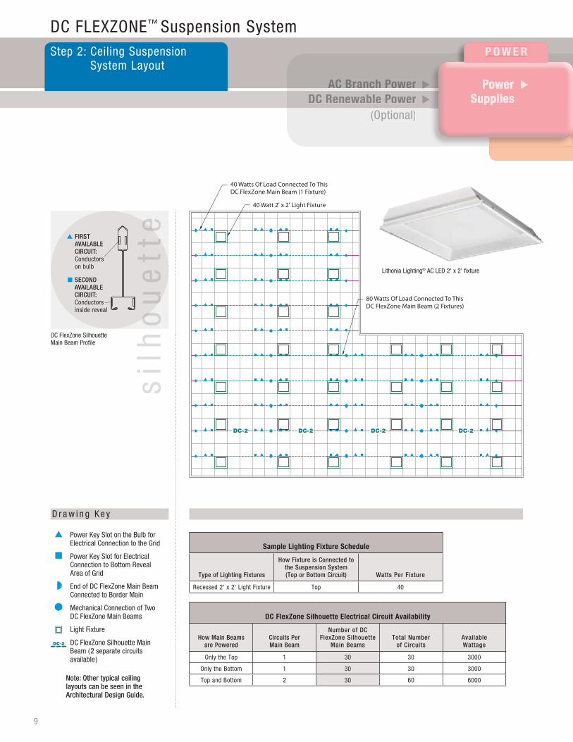
80 Watts Of Load Connected To This DC FlexZone Main Beam (2 Fixtures)
40 Watt 2' x 2' Light Fixture
40 Watts Of Load Connected To This DC FlexZone Main Beam (1 Fixture)
DC FLEXZONE™ Suspension SystemStep 2: Ceiling Suspension
System Layout
D r a w i n g K e y
Sample lighting Fixture Schedule
Type of Lighting Fixtures
How Fixture is Connected to the Suspension System (Top or Bottom Circuit) Watts Per Fixture
Recessed 2' x 2' Light Fixture Top 40
Note: Other typical ceiling layouts can be seen in the Architectural Design Guide.
DC FlexZone Silhouette electrical Circuit Availability
How Main Beams are Powered
Circuits Per Main Beam
Number of DC FlexZone Silhouette
Main BeamsTotal Number
of CircuitsAvailable Wattage
Only the Top 1 30 30 3000
Only the Bottom 1 30 30 3000
Top and Bottom 2 30 60 6000
DC FlexZone Silhouette Main Beam Profile
▲ FIRST AVAILABLE CIRCUIT: Conductors on bulb
■ SECOND AVAILABLE CIRCUIT: Conductors inside reveal
sil
ho
ue
tte
sil
ho
ue
tte
sil
ho
ue
tte
9
Lithonia Lighting® AC LED 2' x 2' fixture
I n F R A S T R u C T u R e P E R I P H E R A L S
Lights, Lights, Lights, Sensors, etc.
▲
Device CablingDevice Cabling& Interconnects
▲▲
Structured Structured Cabling &
InterconnectsInterconnects
▲▲▲▲▲▲
Powered Bus BarComponents
( DC FlexZone Suspension System )
▲
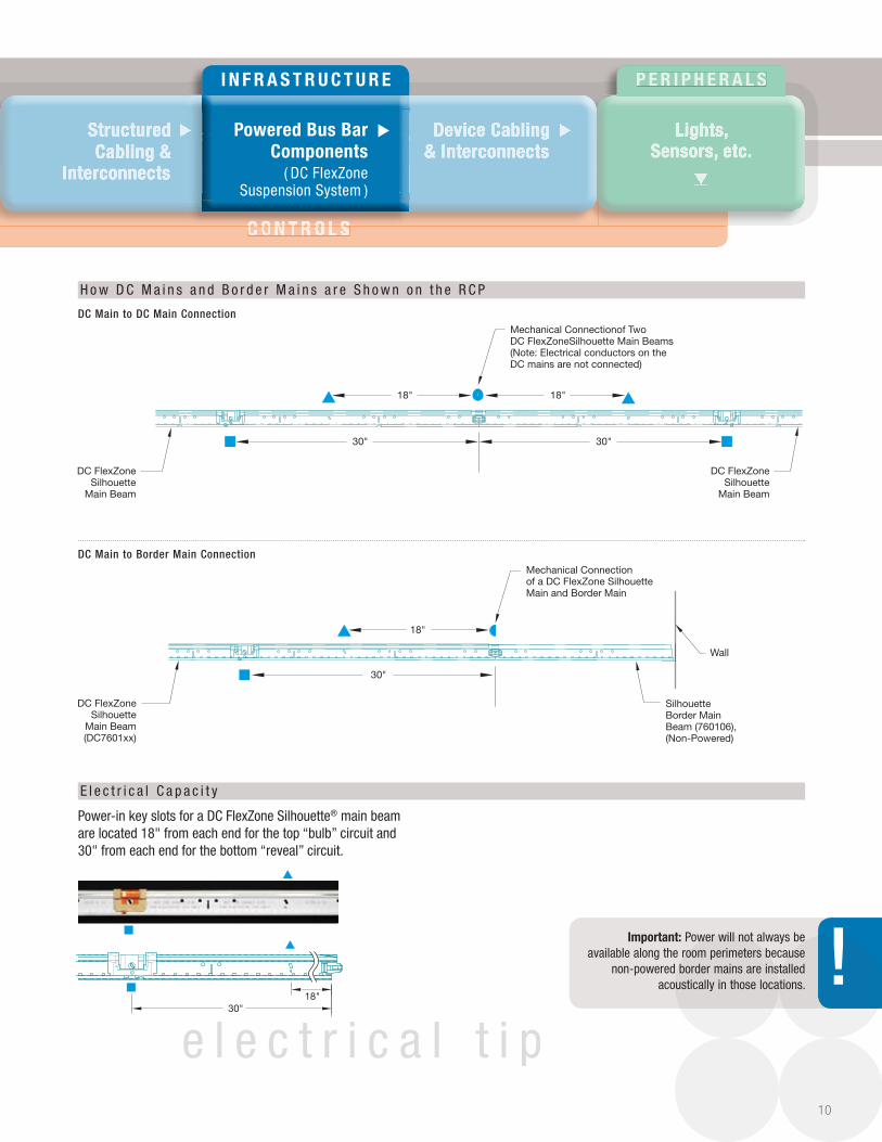
30" 30"
Mechanical Connectionof Two DC FlexZoneSilhouette Main Beams(Note: Electrical conductors on the DC mains are not connected)
DC FlexZoneSilhouette
Main Beam
DC FlexZoneSilhouette
Main Beam
18" 18"
18"
30"
Wall
DC FlexZoneSilhouette
Main Beam(DC7601xx)
Silhouette Border Main Beam (760106),(Non-Powered)
Mechanical Connection of a DC FlexZone Silhouette Main and Border Main
18"30"
C O N T R O L SC O N T R O L S
H o w D C M a i n s a n d B o r d e r M a i n s a r e S h o w n o n t h e R C P
DC Main to DC Main Connection
DC Main to Border Main Connection
Power-in key slots for a DC FlexZone Silhouette® main beam are located 18" from each end for the top “bulb” circuit and 30" from each end for the bottom “reveal” circuit.
E l e c t r i c a l C a p a c i t y
e l e c t r i c a l t i p
Important: Power will not always be available along the room perimeters because
non-powered border mains are installed acoustically in those locations.
10
!
P o W e R
Power Supplies
AC Branch PowerAC Branch PowerDC Renewable Power
(Optional)
▲ ▲
▲ ▲
▲ ▲
▲ ▲
▲ ▲
▲ ▲
▲
V e r i f y V o l t a g e s A v a i l a b l e
2 SeS units:
400 - 500 sf
1 PSM unit:800 -1000 sf
11
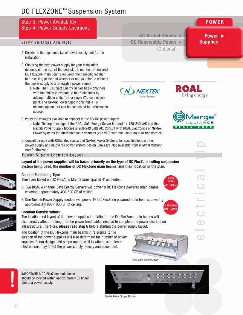
layout of the power supplies will be based primarily on the type of DC FlexZone ceiling suspension system being used, the number of DC FlexZone main beams, and their location in the plan.
General estimating Tips: These are based on DC FlexZone Main Beams spaced 4' on center.
E. Two ROAL 4 channel Safe Energy Servers will power 8 DC FlexZone powered main beams, covering approximately 400-500 SF of ceiling.
F. One Nextek Power Supply module will power 16 DC FlexZone powered main beams, covering approximately 800-1000 SF of ceiling.
location Considerations: The location and layout of the power supplies in relation to the DC FlexZone main beams will also directly affect the length of the power feed cables needed to complete the power distribution infrastructure. Therefore, please read step 6 before starting the power supply layout.
The location of the DC FlexZone main beams in reference to the location of the power supplies will also determine the number of power supplies. Room design, odd shape rooms, wall locations, and plenum obstructions may affect the power supply density and placement.
A. Decide on the type and size of power supply unit for the installation.
B. Choosing the best power supply for your installation depends on the size of the project, the number of powered DC FlexZone main beams required, their specific location in the ceiling plane and whether or not you plan to connect the power supply to a renewable power source.
a. Note: The ROAL Safe Energy Server has 4 channels with the ability to expand up to 16 channels by adding multiple units from a single VAC connection point. The Nextek Power Supply only has a 16 channel option, but can be connected to a renewable source.
C. Verify the voltages available to connect to the AC-DC power supply. a. Note: The input voltage of the ROAL Safe Energy Server is rated for 120-240 VAC and the
Nextek Power Supply Module is 208-240 Volts AC. Consult with ROAL Electronics or Nextek Power Systems for alternative input voltages (277 VAC) with the use of an auto transformer.
D. Consult directly with ROAL Electronics and Nextek Power Systems for specifications on their power supply and an overall power system design. Links are also available from www.armstrong.com/dcflexzone
DC FLEXZONE™ Suspension SystemStep 3: Power AvailabilityStep 4: Power Supply Locations
P o w e r S u p p l y L o c a t i o n L a y o u t
IMPORTANT: A DC FlexZone main beam should be located within approximately 30 linear feet of a power supply.
Nextek Power Supply Module
ele
ctr
ica
l ti
pe
lec
tric
al
tip
!ROAL Safe Energy Server

I N F R A S T R U C T U R E P E R I P H E R A L S
Lights, Lights, Lights, Sensors, etc.
▲
Structured Structured Cabling &
InterconnectsInterconnects
Device CablingDevice Cabling& Interconnects
Powered Bus BarPowered Bus BarPowered Bus BarComponents
( DC FlexZoneSuspension System )Suspension System )
▲▲▲ ▲▲▲▲▲
Two 4 Channel ROAL Safe Energy Servers120-240 VAC
DC-2 DC-2 DC-2 DC-2
16 Channel NextekPower Supply Module
208-240 VAC
12
Power Key Slot on the Bulb for Electrical Connection to the Grid
Power Key Slot for ElectricalConnection to Bottom RevealArea of Grid
End of DC FlexZone Main BeamConnected to Border Main
Mechanical Connection of TwoDC FlexZone Main Beams
Power Supply Module or Safe Energy Server
C O N T R O L SC O N T R O L S
D r a w i n g K e y
DC FlexZone Suprafine Main Beam Profile
▲ AVAILABLE CIRCUIT: Conductorson bulb
DC FlexZone Silhouette Main Beam Profile
▲ FIRST AVAILABLE CIRCUIT: Conductors on bulb
■ SECOND AVAILABLE CIRCUIT: Conductors inside reveal
sil
ho
ue
tte
su
pra
fin
e

P o W e R
Power Supplies
AC Branch PowerAC Branch PowerDC Renewable Power
(Optional)
▲ ▲
▲ ▲
▲ ▲
▲ ▲
▲ ▲
▲ ▲
▲
S e l e c t i n g t h e D C - D C C o n v e r t e r
13
DC FLEXZONE™ Suspension SystemStep 5: DC Renewable Power
(Optional)
D C - D C C o n v e r t e r S e l e c t i o n
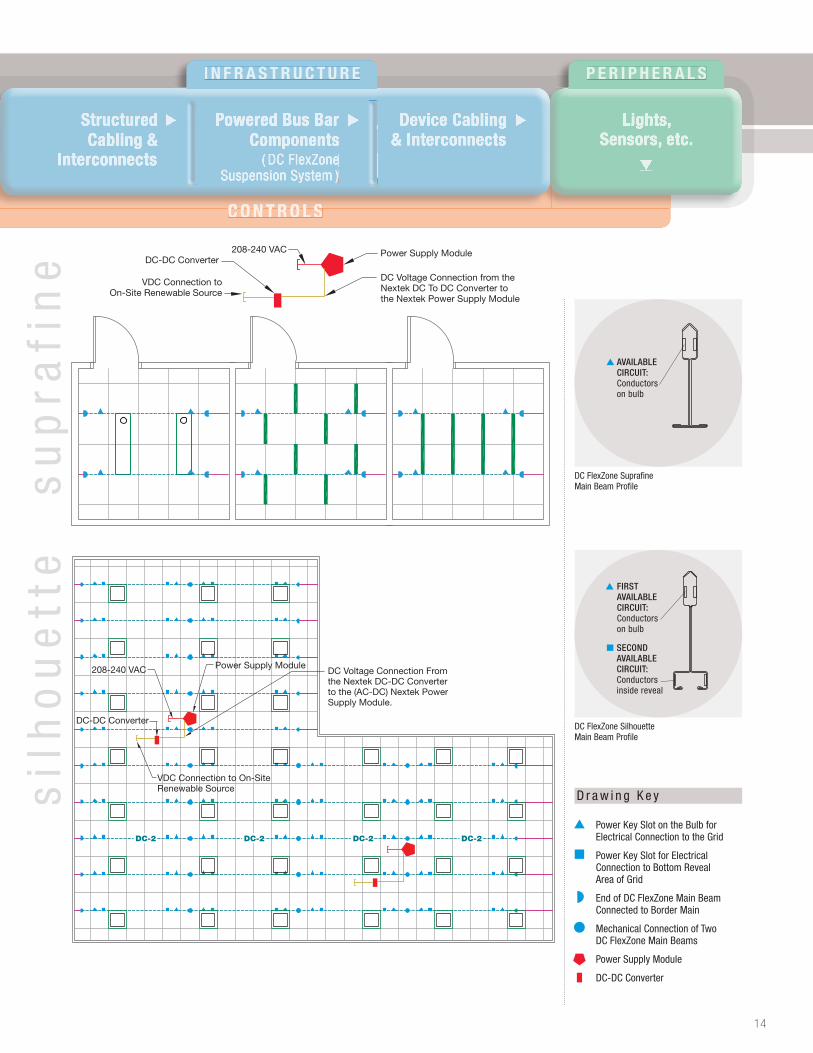
The DC-DC converter should be used with a renewable power source.
note: The Nextek DC-DC converter must be used in conjunction with the AC-DC power supply module on a one-to-one scale.
Consult directly with Nextek Power Systems on DC-DC power converter specifications, wire sizing and overall power system design. Links are also available from www.armstrong.com/dcflexzone
IMPORTANT: A DC-DC converter should be located within approximately 10 feet of an AC-DC power supply.
location and layout of the DC-DC converter will be based primarily on the location of the AC-DC power supply.
Guidelines for selecting a DC-DC converter:
location Considerations: The location and layout of the DC-DC converter shall be in close proximity to the location of the AC-DC power supply module.
Nextek DC-DC converter
ele
ctr
ica
l ti
p
!
▲
DC-DC Converter Size low Voltage high Voltage Fixed Voltage
output Power(To an AC-DC Power
Supply Module)1600 Watts 1600 Watts 1600 Watts
Range of Input Voltage (From Renewable Source)
70-240 Volts DC 240-390 Volts DC 350-400 Volts DC
output Voltage (From DC-DC Converter)
24.5 Volts DC 24.5 Volts DC 24.5 Volts DC
I N F R A S T R U C T U R E P E R I P H E R A L S
C O N T R O L SC O N T R O L S
Lights, Lights, Lights, Sensors, etc.
▲
Structured Structured Cabling &
InterconnectsInterconnects
Device CablingDevice Cabling& Interconnects
Powered Bus BarPowered Bus BarPowered Bus BarComponents
( DC FlexZoneSuspension System )Suspension System )
▲▲▲ ▲▲▲▲▲
Power Supply Module208-240 VAC
VDC Connection toOn-Site Renewable Source
DC-DC Converter
DC Voltage Connection from the Nextek DC To DC Converter to the Nextek Power Supply Module
DC-2 DC-2 DC-2 DC-2
Power Supply Module208-240 VAC DC Voltage Connection From the Nextek DC-DC Converter to the (AC-DC) Nextek Power Supply Module.
DC-DC Converter
VDC Connection to On-Site Renewable Source
14
Power Key Slot on the Bulb for Electrical Connection to the Grid
Power Key Slot for ElectricalConnection to Bottom RevealArea of Grid
End of DC FlexZone Main BeamConnected to Border Main
Mechanical Connection of TwoDC FlexZone Main Beams
Power Supply Module
DC-DC Converter
D r a w i n g K e y
DC FlexZone Suprafine Main Beam Profile
▲ AVAILABLE CIRCUIT: Conductors on bulb
DC FlexZone Silhouette Main Beam Profile
▲ FIRST AVAILABLE CIRCUIT: Conductors on bulb
■ SECOND AVAILABLE CIRCUIT: Conductors inside reveal
sil
ho
ue
tte
su
pra
fin
e
P O W E R
AC Branch PowerAC Branch PowerDC Renewable Power
(Optional)
▲ ▲
▲ ▲
▲ ▲
▲ ▲
▲ ▲
▲ ▲
Power Power Power Supplies
▲▲▲
Structured Cabling &
Interconnects
Silhouette grid Suprafine grid Silhouette grid Suprafine grid
DC FLEXZONE™ Suspension SystemStep 6: Power Cable Layout
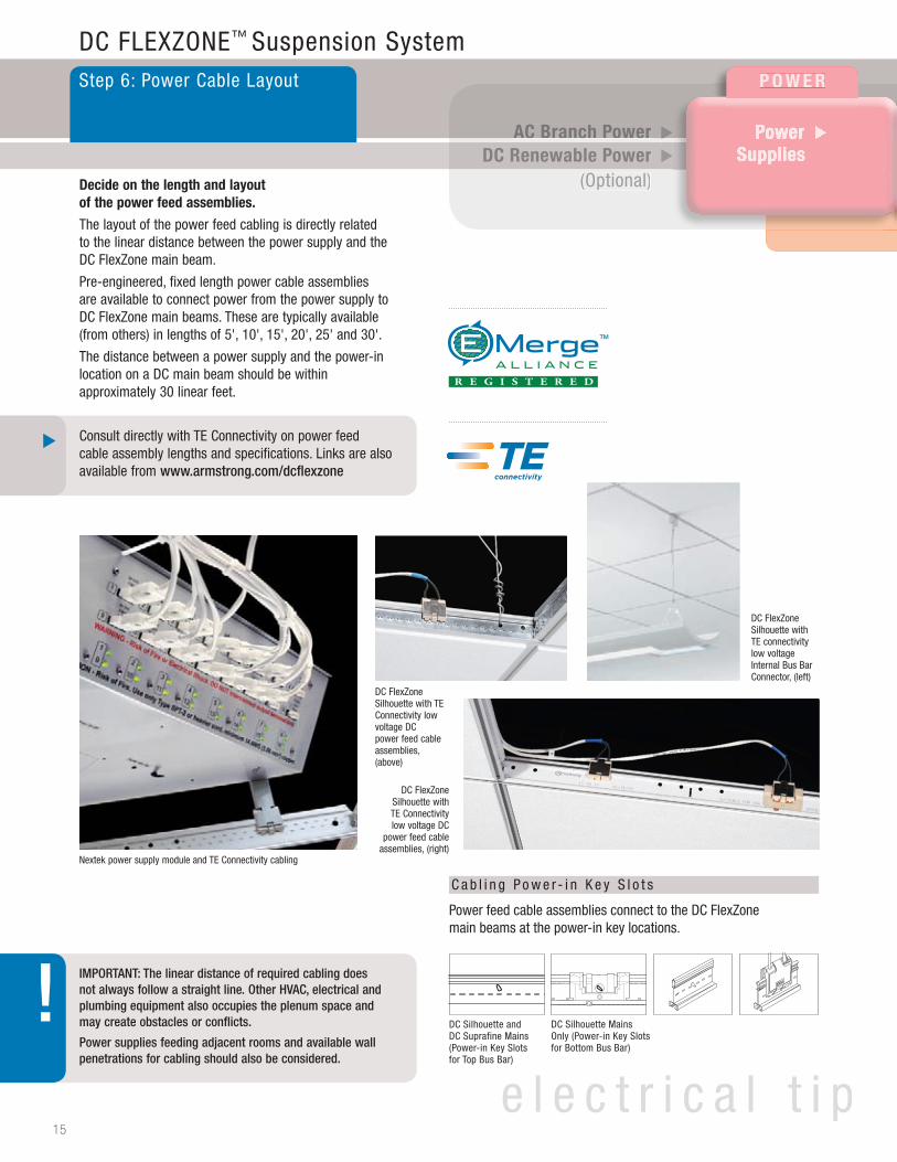
Decide on the length and layout of the power feed assemblies.
The layout of the power feed cabling is directly related to the linear distance between the power supply and the DC FlexZone main beam.
Pre-engineered, fixed length power cable assemblies are available to connect power from the power supply to DC FlexZone main beams. These are typically available (from others) in lengths of 5', 10', 15', 20', 25' and 30'.
The distance between a power supply and the power-in location on a DC main beam should be within approximately 30 linear feet.
Consult directly with TE Connectivity on power feed cable assembly lengths and specifications. Links are also available from www.armstrong.com/dcflexzone
IMPORTANT: The linear distance of required cabling does not always follow a straight line. Other HVAC, electrical and plumbing equipment also occupies the plenum space and may create obstacles or conflicts.
Power supplies feeding adjacent rooms and available wall penetrations for cabling should also be considered.
Nextek power supply module and TE Connectivity cabling
DC Silhouette and DC Suprafine Mains (Power-in Key Slots for Top Bus Bar)
DC Silhouette Mains Only (Power-in Key Slots for Bottom Bus Bar)
Power feed cable assemblies connect to the DC FlexZone main beams at the power-in key locations.
C a b l i n g P o w e r - i n K e y S l o t s
DC FlexZone Silhouette with TE Connectivity low voltage DC power feed cable assemblies, (above)
DC FlexZone Silhouette with TE connectivity low voltage Internal Bus Bar Connector, (left)
DC FlexZone Silhouette with TE Connectivity low voltage DC
power feed cable assemblies, (right)
15
e l e c t r i c a l t i p
▲
!
I n F R A S T R u C T u R e P E R I P H E R A L S
C O N T R O L SC O N T R O L S
Lights, Lights, Lights, Sensors, etc.
▲
Device CablingDevice Cabling& Interconnects
Powered Bus BarPowered Bus BarPowered Bus BarComponents
( DC FlexZoneSuspension System )Suspension System )
▲▲▲▲▲
Structured Cabling &
Interconnects
▲
20'20'
15'
15'
15'
10'
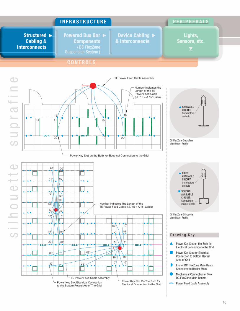
TE Power Feed Cable Assembly
Number Indicates the Length of the TE Power Feed Cable (I.E. 15 = A 15' Cable)
Power Key Slot on the Bulb for Electrical Connection to the Grid
DC-1 DC-1 DC-1
DC-2 DC-2DC-2DC-2
Power Key Slot Electrical Connection to the Bottom Reveal Are of The Grid
TE Power Feed Cable AssemblyPower Key Slot On The Bulb for Electrical Connection to the Grid
Number Indicates The Length of the TE Power Feed Cable (I.E. 15 = A 15' Cable)
15'
10'
10'
5'5'
10' 10'
20' 20'
15'
10'10'
20' 20'
15'15'
30'
30' 20'
20'
10' 10'
10'10'
10' 10'
5'5'
15' 10'
Power Key Slot on the Bulb for Electrical Connection to the Grid
Power Key Slot for ElectricalConnection to Bottom RevealArea of Grid
End of DC FlexZone Main BeamConnected to Border Main
Mechanical Connection of TwoDC FlexZone Main Beams
Power Feed Cable Assembly
D r a w i n g K e y
DC FlexZone Suprafine Main Beam Profile
▲ AVAILABLE CIRCUIT: Conductorson bulb
DC FlexZone Silhouette Main Beam Profile
▲ FIRST AVAILABLE CIRCUIT: Conductors on bulb
■ SECOND AVAILABLE CIRCUIT: Conductors inside reveal
16
sil
ho
ue
tte
su
pra
fin
e
P O W E R
AC Branch PowerAC Branch PowerDC Renewable Power
(Optional)
▲ ▲
▲ ▲
▲ ▲
▲ ▲
▲ ▲
▲ ▲
Power Power Power Supplies
▲▲▲
▲▲
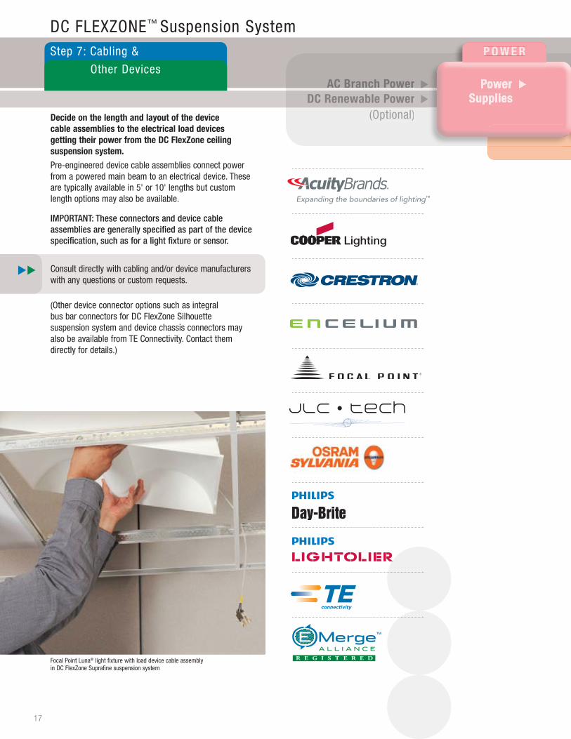
DC FLEXZONE™ Suspension SystemStep 7: Cabling &
Other Devices
Focal Point Luna® light fixture with load device cable assembly in DC FlexZone Suprafine suspension system
Decide on the length and layout of the device cable assemblies to the electrical load devices getting their power from the DC FlexZone ceiling suspension system.
Pre-engineered device cable assemblies connect power from a powered main beam to an electrical device. These are typically available in 5' or 10' lengths but custom length options may also be available.
IMPORTANT: These connectors and device cable assemblies are generally specified as part of the device specification, such as for a light fixture or sensor.
Consult directly with cabling and/or device manufacturers with any questions or custom requests.
(Other device connector options such as integral bus bar connectors for DC FlexZone Silhouette suspension system and device chassis connectors may also be available from TE Connectivity. Contact them directly for details.)
17
I n F R A S T R u C T u R e P e R I P h e R A l S
lights, Sensors, etc.
▲
Structured Structured Cabling &
InterconnectsInterconnects
Powered Bus BarPowered Bus BarPowered Bus BarComponents
( DC FlexZoneSuspension System )Suspension System )
▲▲▲ ▲▲▲
Device Cabling& Interconnects
▲
Power Key Slot on the Bulb for Electrical Connection to the Grid
Power Key Slot for ElectricalConnection to Bottom RevealArea of Grid
End of DC FlexZone Main BeamConnected to Border Main
Mechanical Connection of TwoDC FlexZone Main Beams
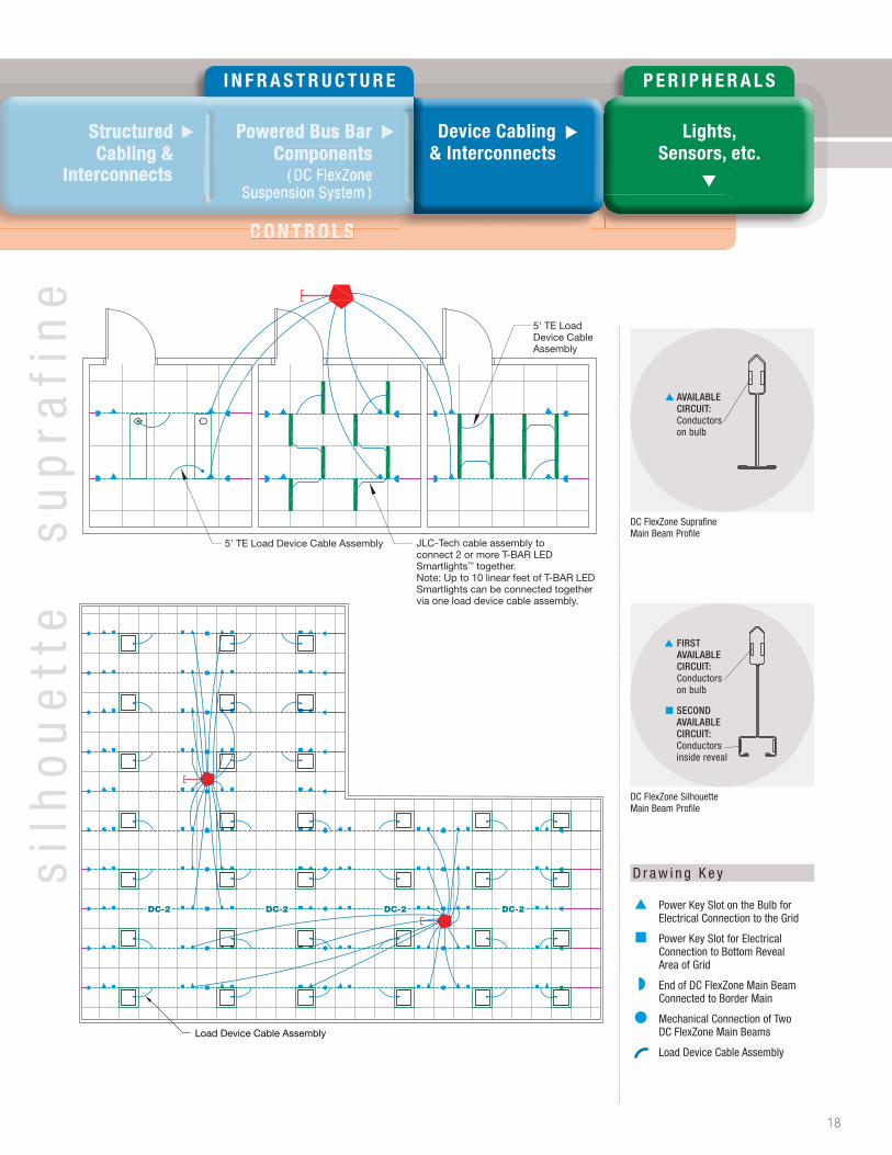
Load Device Cable Assembly
DC-2 DC-2 DC-2 DC-2
Load Device Cable Assembly
sil
ho
ue
tte
su
pra
fin
e
C O N T R O L SC O N T R O L S
D r a w i n g K e y
DC FlexZone Suprafine Main Beam Profile
▲ AVAILABLE CIRCUIT: Conductorson bulb
DC FlexZone Silhouette Main Beam Profile
▲ FIRST AVAILABLE CIRCUIT: Conductors on bulb
■ SECOND AVAILABLE CIRCUIT: Conductors inside reveal
18
5' TE Load Device Cable Assembly
5' TE Load Device Cable Assembly JLC-Tech cable assembly toconnect 2 or more T-BAR LED Smartlights™ together.Note: Up to 10 linear feet of T-BAR LED Smartlights can be connected togethervia one load device cable assembly.
Power Supply Module208-240 VAC
VDC Connection toOn-Site Renewable Source
DC-DC Converter
DC Voltage Connection from the Nextek DC To DC Converter to the Nextek Power Supply Module
P O W E R
C o n T R o l S
AC Branch PowerAC Branch PowerDC Renewable Power
(Optional)
▲ ▲
▲ ▲
▲ ▲
▲ ▲
▲ ▲
▲ ▲
Power Power Power Supplies
▲▲▲
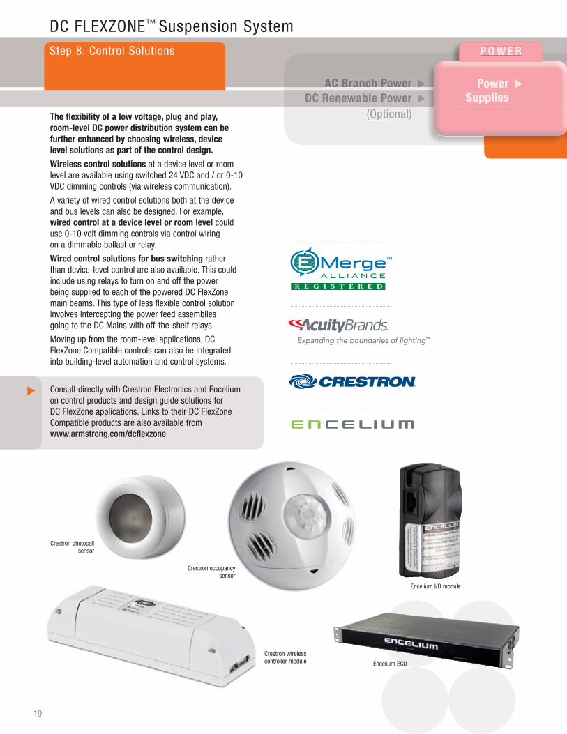
DC FLEXZONE™ Suspension SystemStep 8: Control Solutions
The flexibility of a low voltage, plug and play, room-level DC power distribution system can be further enhanced by choosing wireless, device level solutions as part of the control design.
Wireless control solutions at a device level or room level are available using switched 24 VDC and / or 0-10 VDC dimming controls (via wireless communication).
A variety of wired control solutions both at the device and bus levels can also be designed. For example, wired control at a device level or room level could use 0-10 volt dimming controls via control wiring on a dimmable ballast or relay.
Wired control solutions for bus switching rather than device-level control are also available. This could include using relays to turn on and off the power being supplied to each of the powered DC FlexZone main beams. This type of less flexible control solution involves intercepting the power feed assemblies going to the DC Mains with off-the-shelf relays.
Moving up from the room-level applications, DC FlexZone Compatible controls can also be integrated into building-level automation and control systems.
Consult directly with Crestron Electronics and Encelium on control products and design guide solutions for DC FlexZone applications. Links to their DC FlexZone Compatible products are also available from www.armstrong.com/dcflexzone
Crestron photocell sensor
Crestron occupancy sensor
Crestron wireless controller module
Encelium I/O module
Encelium ECU
19
▲

I N F R A S T R U C T U R E P E R I P H E R A L S
C o n T R o l SC o n T R o l S
Lights, Lights, Lights, Sensors, etc.
▲
Structured Structured Cabling &
InterconnectsInterconnects
Device CablingDevice Cabling& Interconnects
Powered Bus BarPowered Bus BarPowered Bus BarComponents
( DC FlexZoneSuspension System )Suspension System )
▲▲▲ ▲▲▲▲▲
OSOSOS
SSS
Wall Keypad Occupancy Sensor
Wireless Controller
DC-1 DC-1 DC-1
OS
OS
DC-2 DC-2 DC-2 DC-2
S
PS PS
Photocell SensorWireless Controller
Occupancy Sensor
Wall Keypad
Power Key Slot on the Bulb for Electrical Connection to the Grid
Power Key Slot for ElectricalConnection to Bottom RevealArea of Grid
End of DC FlexZone Main BeamConnected to Border Main
Mechanical Connection of TwoDC FlexZone Main Beams
Occupancy Sensor
Photocell Sensor
Wireless Controller
Wall Keypad
OS
PS
S
D r a w i n g K e y
DC FlexZone Suprafine Main Beam Profile
▲ AVAILABLE CIRCUIT: Conductorson bulb
DC FlexZone Silhouette Main Beam Profile
▲ FIRST AVAILABLE CIRCUIT: Conductors on bulb
■ SECOND AVAILABLE CIRCUIT: Conductors inside reveal
20
sil
ho
ue
tte
su
pra
fin
e
P O W E R
AC Branch PowerAC Branch PowerDC Renewable Power
(Optional)
▲ ▲
▲ ▲
▲ ▲
▲ ▲
▲ ▲
▲ ▲
Power Power Power Supplies
▲▲▲
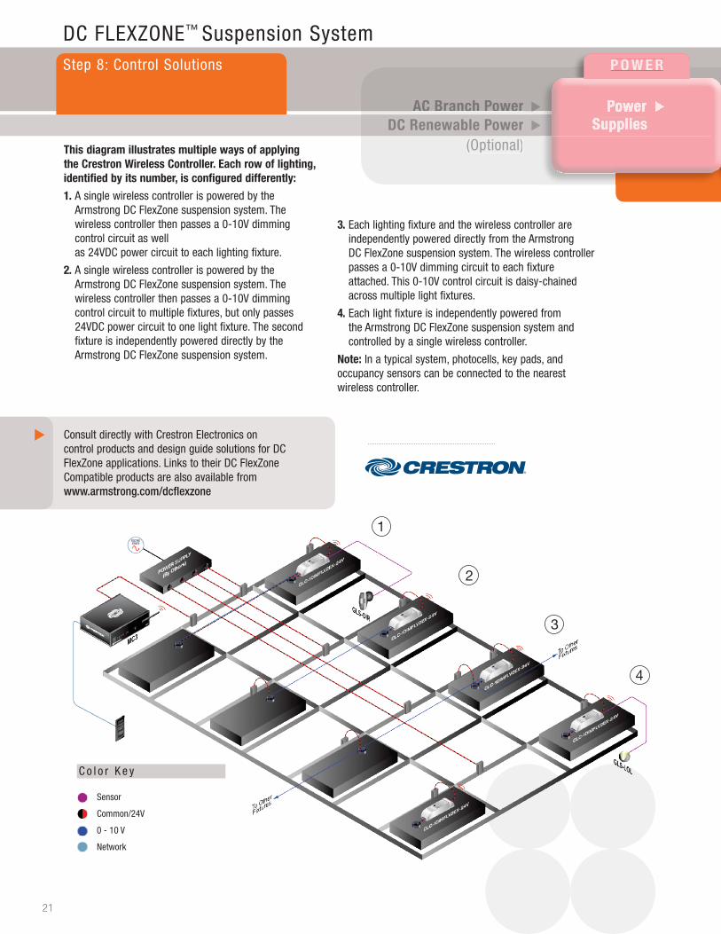
3. Each lighting fixture and the wireless controller areindependently powered directly from the ArmstrongDC FlexZone suspension system. The wireless controllerpasses a 0-10V dimming circuit to each fixtureattached. This 0-10V control circuit is daisy-chainedacross multiple light fixtures.
4. Each light fixture is independently powered fromthe Armstrong DC FlexZone suspension system andcontrolled by a single wireless controller.
note: In a typical system, photocells, key pads, and occupancy sensors can be connected to the nearest wireless controller.
DC FLEXZONE™ Suspension SystemStep 8: Control Solutions
This diagram illustrates multiple ways of applying the Crestron Wireless Controller. each row of lighting, identified by its number, is configured differently:
1. A single wireless controller is powered by theArmstrong DC FlexZone suspension system. Thewireless controller then passes a 0-10V dimmingcontrol circuit as wellas 24VDC power circuit to each lighting fixture.
2. A single wireless controller is powered by theArmstrong DC FlexZone suspension system. Thewireless controller then passes a 0-10V dimmingcontrol circuit to multiple fixtures, but only passes24VDC power circuit to one light fixture. The secondfixture is independently powered directly by theArmstrong DC FlexZone suspension system.
Consult directly with Crestron Electronics on control products and design guide solutions for DC FlexZone applications. Links to their DC FlexZone Compatible products are also available from www.armstrong.com/dcflexzone
21
▲
C o l o r K e y
Sensor
Common/24V
0 - 10 V
Network
1
2
4
3
C o n T R o l S

I N F R A S T R U C T U R E P E R I P H E R A L S
Lights, Lights, Lights, Sensors, etc.
▲
Structured Structured Cabling &
InterconnectsInterconnects
Device CablingDevice Cabling& Interconnects
Powered Bus BarPowered Bus BarPowered Bus BarComponents
( DC FlexZoneSuspension System )Suspension System )
▲▲▲ ▲▲▲▲▲
Photo Sensor
TelephoneSystem
EnergyMeter ECU SSU
I/O Module
ECU
ECU
Enc
eliu
m E
ther
net
Net
wo
rk
Secure Ethernet (existing)Tenant A
PCH WallControl
To additionaldevices
To additionaldevices
Secure Ethernet (existing)Tenant B
Occ.Sensor
GreenBus6 Channels x 75 devicesApprox, 25,000 sq. ft.
Intranet/InternetConnection
GreenBus6 Channels x 75 devicesApprox, 25,000 sq. ft.
GreenBus6 Channels x 75 devicesApprox, 25,000 sq. ft.
GreenBus6 Channels x 75 devicesApprox, 25,000 sq. ft.
This diagram illustrates multiple ways of applying the encelium lighting Control System for smart buildings.
The ENCELIUM™ Energy Management System (EMS) was designed from the ground up as an integrated lighting control and energy management system that greatly reduces lighting energy consumption while improving lighting quality and personal lighting comfort. Addressable
fixture level dimming and switching controls coupled with easy to use control software allows the ENCELIUM EMS to respond dynamically to the ever changing characteristics of a building by always providing the right amount of light when and where required.
The GreenBus I™ is a low-cost, high reliability communication means to report sensor information back to the ENCELIUM Energy Management System (EMS). This illustration shows how each component is easily integrated into the EMS. Each light fixture, sensor and wall controller is daisy-chained back to the Energy Control Unit (ECU) using pre-terminated ‘click & go’ GreenBus I™ communication cabling. Based on the position of light fixtures and sensors, an optimum wiring path is determined utilizing supplied pre-terminated cables. As the modules obtain power via the GreenBus I network. ECUs typically control individual floors and are linked via an Ethernet Network. Internet or LAN connection allows Windows floor plan based control software to be operated anywhere on the network.
S y s t e m A r c h i t e c t u r e
Consult directly with Enculium on control products and design guide solutions for DC FlexZone applications. Links to their DC FlexZone Compatible products are also available from www.armstrong.com/dcflexzone
22
▲
C o n T R o l S
Copyright © EMerge Alliance. All rights reserved.
TechLineSM / 1 877 ARMSTRONG
1 877 276 7876
armstrongceilings.com/dcflexzone
BPCS-4325-613
All trademarks used herein are the property of AWI Licensing Company and/or its affiliates and DC FlexZone compatible partners© 2013 AWI Licensing Company • Printed in the United States of America
D C F l e x Z o n e C o m p a t i b l e P a r t n e r s
º Power, infrastructure, lighting, and control companies to help complete your DC power distribution system
º Light fixtures are compatible with DC FlexZone 9/16" Suprafine® and 9/16" Silhouette® with 1/4" reveal
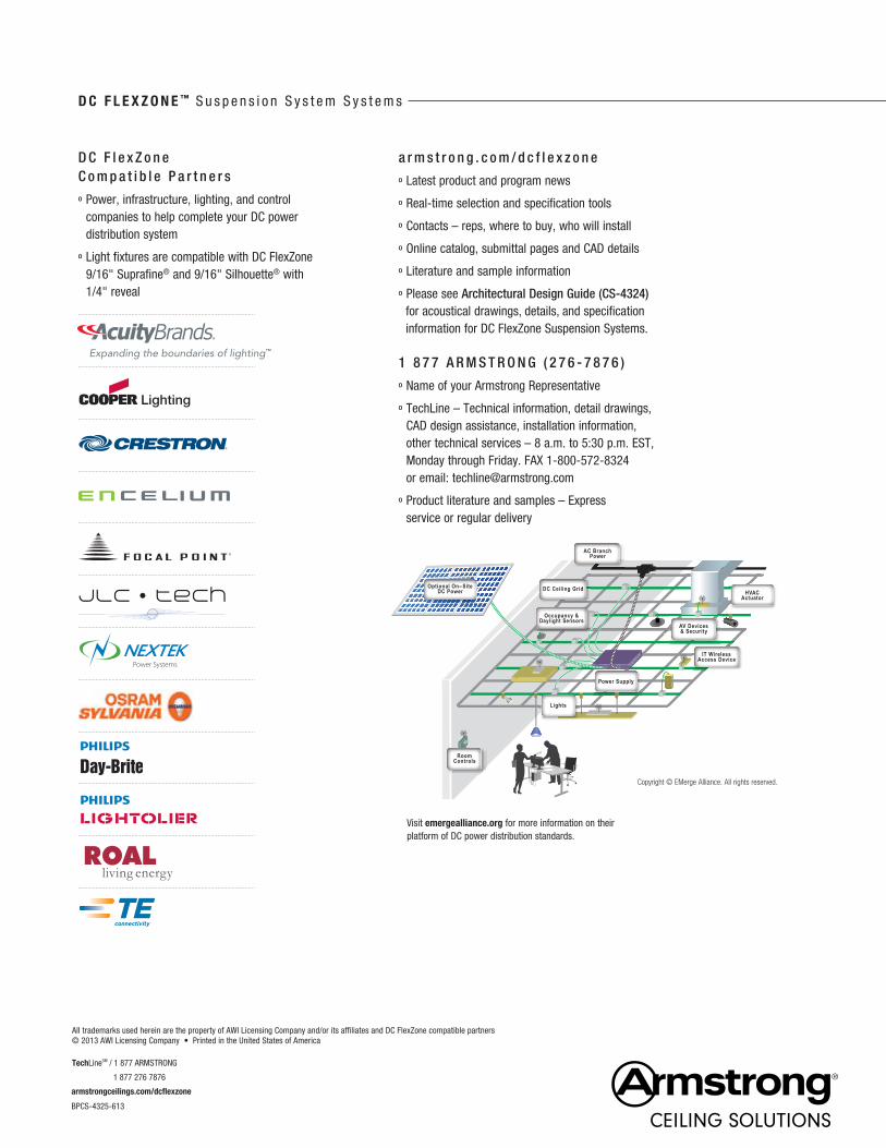
Visit emergealliance.org for more information on their platform of DC power distribution standards.
D C F l e x Z o n e ™ S u s p e n s i o n S y s t e m S y s t e m s
a r m s t r o n g . c o m / d c f l e x z o n e
º Latest product and program news
º Real-time selection and specification tools
º Contacts – reps, where to buy, who will install
º Online catalog, submittal pages and CAD details
º Literature and sample information
º Please see Architectural Design Guide (CS-4324) for acoustical drawings, details, and specification information for DC FlexZone Suspension Systems.
1 8 7 7 A R M S T R O N G ( 2 7 6 - 7 8 7 6 )
º Name of your Armstrong Representative
º TechLine – Technical information, detail drawings, CAD design assistance, installation information, other technical services – 8 a.m. to 5:30 p.m. EST, Monday through Friday. FAX 1-800-572-8324 or email: [email protected]
º Product literature and samples – Express service or regular delivery