Embed Size (px)
Citation preview

DC FUEL FLOW TO FREQUENCY CONVERTER
PRODUCT P/N: 630502
INSTALLATION MANUAL
REV C
Shadin Avionics 6831 Oxford Street
St. Louis Park, MN 55426 USA
Sales: (800)-328-0584
Technical Support: (800)-388-2849 WWW.SHADIN.COM
MANUAL P/N: IM6352

IM6352CG.DOC, DIR. 630502 IM6352 Shadin Avionics
INSTALLATION MANUAL DC FUEL FLOW TO FREQUENCY CONVERTER Rev: C P/N 630502 Page: i of i
PAGE CONTROL CHART
SECTION NO. DESCRIPTION PAGE
1. OVERVIEW
1.1 The Manual 1-1 1.2 Product Description 1-1 1.3 Applications 1-2 1.3 Applications (cont.) 1-3 1.3 Applications (cont.) 1-4 1.4 Specifications 1-5
2. INSTALLATION PROCEDURE
2.1 Mounting 2-1 2.2 Electrical Connections 2-1 2.2.1 Connection to the Power Supply 2-2 2.2.2 Connection to the DC Input Signals 2-2 2.2.3 Connection to the System 2-2
3. ENVIRONMENTAL QUALIFICATION FORM 3-1
Environmental Qualification Form (Cont.) 3-2
4. INSTALLATION DRAWINGS AND INSTALL KIT PARTS LIST Drawing No. Description/ Part Number DATE REV 4005-557 Installation, DC to Frequency Converter 8/26/03 D 4005-558 Installation Wiring, Analog FF to Freq. 8/05/98 C to FADC 4005-854 Installation Wiring, Analog FF to Freq. 3/26/98 A Converter, Beech KingAir Indicators 4005-C49 Installation Wiring, Analog FF to Freq. 2/11/00 A Converter, Cheyene/Citation/Westwind Indicators
N/A Install Kit for 15 Pin D-Sub, IK9337 1/11/06 F
IM6352CG.DOC, DIR. 630502 IM6352 Shadin Avionics
INSTALLATION MANUAL DC FUEL FLOW TO FREQUENCY CONVERTER Rev: C P/N 630502 Page: ii of ii
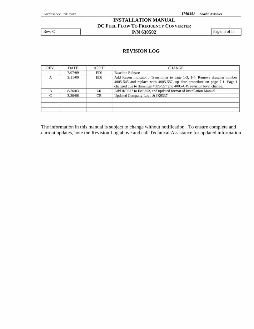
REVISION LOG
REV. DATE APP’D CHANGE – 7/07/99 EDJ Baseline Release A 2/11/00 EDJ Add Ragen Indicator / Transmitter to page 1-3, 1-4. Remove drawing number
4005-545 and replace with 4005-557, up date procedure on page 2-1. Page i changed due to drawings 4005-557 and 4005-C49 revision level change.
B 8/26/03 ZK Add IK9337 to IM6352, and updated format of Installation Manual. C 3/30/06 CB Updated Company Logo & IK9337
The information in this manual is subject to change without notification. To ensure complete and current updates, note the Revision Log above and call Technical Assistance for updated information.

IM6352CG.DOC, DIR. 630502 IM6352 Shadin Avionics
INSTALLATION MANUAL DC FUEL FLOW TO FREQUENCY CONVERTER Rev: C P/N 630502 Page: 1-1
1. OVERVIEW 1.1 The Manual This manual is intended to facilitate the proper installation of the DC Fuel Flow (FF) to
Frequency Converter. Installation instructions should be read and followed. 1.2 Product Description
The purpose of the DC to Frequency Converter is to receive the analog FF signal in the form of a DC voltage and produce a digital output signal with a frequency proportional to the FF signal. The digital output represents the engine fuel flow and is available for use by a standard fuel management system.
The conversion for Left and Right engine fuel flow is defined by the following relation: Freq
OUT = VIN × 122.07 (Hz)
Where VIN is the input voltage ranging from 0 to 10 volts.
P/N 630502
Left DC Input
Right DC Input
Left Frequency O t t
Right Frequency Output
IM6352CG.DOC, DIR. 630502 IM6352 Shadin Avionics
INSTALLATION MANUAL DC FUEL FLOW TO FREQUENCY CONVERTER Rev: C P/N 630502 Page: 1-2
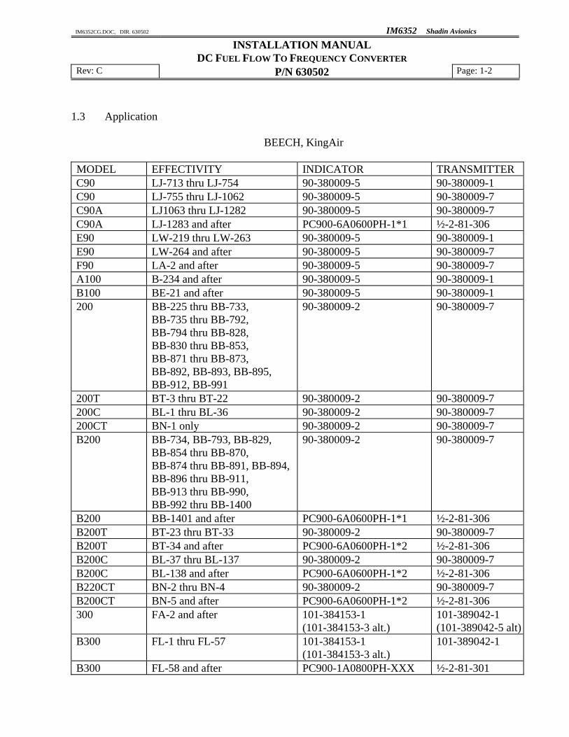
1.3 Application
BEECH, KingAir
MODEL EFFECTIVITY INDICATOR TRANSMITTER C90 LJ-713 thru LJ-754 90-380009-5 90-380009-1 C90 LJ-755 thru LJ-1062 90-380009-5 90-380009-7 C90A LJ1063 thru LJ-1282 90-380009-5 90-380009-7 C90A LJ-1283 and after PC900-6A0600PH-1*1 ½-2-81-306 E90 LW-219 thru LW-263 90-380009-5 90-380009-1 E90 LW-264 and after 90-380009-5 90-380009-7 F90 LA-2 and after 90-380009-5 90-380009-7 A100 B-234 and after 90-380009-5 90-380009-1 B100 BE-21 and after 90-380009-5 90-380009-1 200 BB-225 thru BB-733,
BB-735 thru BB-792, BB-794 thru BB-828, BB-830 thru BB-853, BB-871 thru BB-873, BB-892, BB-893, BB-895, BB-912, BB-991
90-380009-2 90-380009-7
200T BT-3 thru BT-22 90-380009-2 90-380009-7 200C BL-1 thru BL-36 90-380009-2 90-380009-7 200CT BN-1 only 90-380009-2 90-380009-7 B200 BB-734, BB-793, BB-829,
BB-854 thru BB-870, BB-874 thru BB-891, BB-894, BB-896 thru BB-911, BB-913 thru BB-990, BB-992 thru BB-1400
90-380009-2 90-380009-7
B200 BB-1401 and after PC900-6A0600PH-1*1 ½-2-81-306 B200T BT-23 thru BT-33 90-380009-2 90-380009-7 B200T BT-34 and after PC900-6A0600PH-1*2 ½-2-81-306 B200C BL-37 thru BL-137 90-380009-2 90-380009-7 B200C BL-138 and after PC900-6A0600PH-1*2 ½-2-81-306 B220CT BN-2 thru BN-4 90-380009-2 90-380009-7 B200CT BN-5 and after PC900-6A0600PH-1*2 ½-2-81-306 300 FA-2 and after 101-384153-1
(101-384153-3 alt.) 101-389042-1 (101-389042-5 alt)
B300 FL-1 thru FL-57 101-384153-1 (101-384153-3 alt.)
101-389042-1
B300 FL-58 and after PC900-1A0800PH-XXX ½-2-81-301

IM6352CG.DOC, DIR. 630502 IM6352 Shadin Avionics
INSTALLATION MANUAL DC FUEL FLOW TO FREQUENCY CONVERTER Rev: C P/N 630502 Page: 1-3
Application (Cont.)
BEECH, KingAir (cont.)
MODEL EFFECTIVITY INDICATOR TRANSMITTER
B300C FM-1 only
101-384153-1 (101-384153-3 alt.)
101-389042-5
B300C FM-2 and after PC900-1A0800PH-XXX ½-2-81-301 1900C UC-1 thru UC-174
(Configuration 2) PC900-1A0800PH-XXX ½-2-81-301
1900C UD-1 thru UD-6 (Configuration 2)
PC900-1A0800PH-XXX ½-2-81-301
1900D UE-1 and after PC900-1A0800PH-XXX ½-2-81-301
PIPER, Cheyene
MODEL EFFECTIVITY INDICATOR TRANSMITTER
PA-31T(1,2) For units w/indicator & transmitter listed, only
3265013-0601 (RAGEN) 3268011-0101
PA-31T(1,2) For units w/indicator & transmitter listed, only
3260513-1201 (RAGEN) TFF-2905-9
CESSNA, Citation
MODEL EFFECTIVITY INDICATOR TRANSMITTER
500, 501, 550, 551, S550
All Units 101-�-� 393002-009 Simmons/
(9912049-2) Cessna or 2) VSDL-OC208E Ametek or 3) 9912147-16 Cessna
NA
ISRAELI AIRCRAFT IND., Westwind
MODEL EFFECTIVITY INDICATOR TRANSMITTER
1124 All Units 1291-2 (RAGEN) 151-909-001 (GULL)
The DC Fuel Flow to Frequency Converter is required if the receiving device uses a digital frequency signal input for fuel flow information and the fuel flow sensor or indicator provides an analog DC signal that represents Fuel Flow information. This converter does not calculate an offset and it is necessary that the receiving device will correct for the offset, if the fuel system exhibits an offset.

IM6352CG.DOC, DIR. 630502 IM6352 Shadin Avionics
INSTALLATION MANUAL DC FUEL FLOW TO FREQUENCY CONVERTER Rev: C P/N 630502 Page: 1-4
The following table shows the K-Factor and offset to be configured for receiving devices with digital frequency fuel flow signal input.
Indicator P/N Digi-, Mini-, Microflo Airdata (F/ADC200/2000) Digidata Beech King Air
K-factor (ppg)
Offset (Hz)
K-factor (ppg)
Offset (Hz)
K-factor (ppg)
Offset (Hz)
90-380009-2 49,050 24 49,050 24 49,050 24 90-380009-5 49,050 24 49,050 24 49,050 24 101-384009-1 49,050 24 49,050 24 49,050 24 101-384153-1,3 19,647 0 19,647 0 19,647 0 PC900-6A0600-XXX 24,599 0 24,599 0 24,599 0 PC900-1A0750-XXX 19,679 0 19,679 0 19,679 0 PC900-1A0800-XXX 18,449 0 18,449 0 18,449 0 Piper Cheyene
3265013-0601 Ragen 29,470 0 29,470 0 29,470 0 3260513-1201 Ragen 29,470 0 29,470 0 29,470 0 Cessna Citation
393002-009 Simmons 9912049-2 Cessna
9,400 0 9,400 0 9,400 0
VSDL-OC208E 10,400 0 10,400 0 10,400 0 9912147-16 10,400 0 10,400 0 10,400 0 Israeli Aircraft Ind. Westwind
1291-2 (Ragen) 6700 0 6700 0 6700 0 AIRDATA P/N 9628X0(A)-1 where X is 1, 2, or 3, A is optional DIGIDATA P/N 912802 DIGIFLO P/N 9105XYP where X is 1, 2, or 3, Y is 0, 1, 2, 3, 4, 5, 6, 7, 8, 9 or A P/N 9105XY-46 where X is 1, 2, or 3, Y is 0, 1, 2, 3, 4, 5, 6, 7, 8, 9 or A MICROFLO P/N 9120XX(T)-38D where XX is 21, 22, 25, 26, 27, 28, 41, 42, 45, 46, 47, or 48 MINIFLO P/N 9120XX(T)-D where XX is 21, 22, 25, 26, 27, 28, 41, 42, 45, 46, 47, or 48

IM6352CG.DOC, DIR. 630502 IM6352 Shadin Avionics
INSTALLATION MANUAL DC FUEL FLOW TO FREQUENCY CONVERTER Rev: C P/N 630502 Page: 1-5
1.4 Specifications
Physical Specifications Box Size (W x L x H) 2.40 x 4.30 x 1.15 (inches) Weight 0.4 lbs
Electrical and Functional Power Supply Voltage +14 to +28 VDC Supply Current 70 mA at 28 VDC Protection Not internally fused Input (two, one per engine)
DC Input Voltage Range 0-10 V Input Impedance >100 MΩ Frequency FF Output (two, one per engine)
Digital Frequency signal output VOL < 0.8 V IMAX = 15mA VOH = 5V IMAX = 0.5mA Pulse Width (VOL) 0.4 ms Max. Frequency, VIN = 10 V 1,221 Hz Environmental RTCA/DO-160C Operating Temperature -30° to +55° C Operating Altitude -1,000 to 55,000 ft Certification TSO-C44b

IM6352CG.DOC, DIR. 630502 IM6352 Shadin Avionics
INSTALLATION MANUAL DC FUEL FLOW TO FREQUENCY CONVERTER Rev: C P/N 630502 Page: 2-1
2. INSTALLATION PROCEDURE 2.1 Mounting The conditions and test required for TSO approval of this article are minimum performance
standards. It is the responsibility of those installing this article either on or within a specific type or class of aircraft to determine that the aircraft installation conditions are within the TSO standards. TSO articles must have separate approval for installation in an aircraft. The article may be installed only if performed under 14 CFR part 43 or the applicable airworthiness requirements.
The converter should be mounted in a dry, temperature stable location with enough distance from motors, pulse generating equipment, relays, and cables carrying high DC or AC current to avoid interference with signals from the fuel flow transmitter(s)/indicator. The converter may be installed in a temperature controlled environment and in a non-pressurized location. In considering location, keep in mind that the converter requires signals from the fuel flow transmitter(s)/indicator. Placement in the front section of the aircraft is favorable in order to keep the harness length to the receiving equipment as short as possible. Refer to installation drawing number 4005-557 for the mounting footprint and overall dimensions.
2.2 Electrical Connections
Use the 15-pin D-sub connector and components provided in the install kit to fabricate the wiring harness. Refer to the installation drawing numbers, 4005-557, 4005-558, 4005-854, and 4005-C49.

IM6352CG.DOC, DIR. 630502 IM6352 Shadin Avionics
INSTALLATION MANUAL DC FUEL FLOW TO FREQUENCY CONVERTER Rev: C P/N 630502 Page: 2-2
2.2.1 Connection to the Power Supply +28VDC. PIN DESCRIPTION
FF Converter J1: 8 to +14 to +28VDC Power In. FF Converter J1: 15 to Power GND. 2.2.2 Connection to the DC Input Signals PIN DESCRIPTION
FF Converter J1: 1 + Right Fuel Flow In FF Converter J1: 2 − Right Fuel Flow In FF Converter J1: 3 GND, Right Fuel Flow In
FF Converter J1: 9 + Left Fuel Flow In FF Converter J1: 10 − Left Fuel Flow In FF Converter J1: 11 GND Left Fuel Flow In
Per Drawing Number 4005-854 and 4005-C49, use MIL SPEC M27500-22-TG-2T-14 shielded cable for analog left and right fuel flow output signals. Terminate cable shield at the Converter end, only.
2.2.3 Connection to the system PIN DESCRIPTION
FF Converter J1: 13 Left Frequency FF Output FF Converter J1: 6 Right Frequency FF Output Per Drawing Number 4005-854 and 4005-C49, use MIL SPEC M27500-22-TG-2T-14
shielded cable for the Converter to Airdata computer connection. Terminate the cable shield at the Airdata computer end, only.

IM6352CG.DOC, DIR. 630502 IM6352 Shadin Avionics
INSTALLATION MANUAL DC FUEL FLOW TO FREQUENCY CONVERTER Rev: C P/N 630502 Page: 3-1
3. ENVIRONMENTAL QUALIFICATION FORM NOMENCLATURE: DC Fuel Flow to Frequency Converter TYPE/MODEL/PART NO: 630502 TSO NUMBER: C44b MANUFACTURER'S SPECIFICATION AND/OR OTHER APPLICABLE SPECIFICATION: Report 4005C MANUFACTURER: Shadin Avionics ADDRESS: 6831 Oxford Street, St. Louis Park, Minnesota 55426-4412 CONDITIONS SECTION DESCRIPTION OF
TESTS CONDUCTED Temperature and Altitude 4.0 Equipment tested to Category F1. Low Temperature High Temperature
4.5.1 4.5.2 & 4.5.3
Low operating Temperature of -30°C.
Altitude Decompression Overpressure
4.6.1 4.6.2 4.6.3
Temperature Variation 5.0 Identified as Category X.
Not tested. Humidity
6.0 Tested to Category A.
Shock Operational Crash Safety
7.0 7.2 7.3.1 & 7.3.2.2
Not tested.
Vibration
8.0 Tested to Category M, N.
Explosion
9.0 Identified as Category X. Not tested.
Waterproofness 10.0 Identified as Category X.
Not tested. Fluids Susceptibility 11.0 Identified as Category X.
Not tested.

IM6352CG.DOC, DIR. 630502 IM6352 Shadin Avionics
INSTALLATION MANUAL DC FUEL FLOW TO FREQUENCY CONVERTER Rev: C P/N 630502 Page: 3-2
NOMENCLATURE: DC Fuel Flow to Frequency Converter TYPE/MODEL/PART NO: 630502 TSO NUMBER: C44b CONDITIONS SECTION DESCRIPTION OF
TESTS CONDUCTED Sand and Dust 12.0 Identified as Category X.
Not tested. Fungus 13.0 Identified as Category X.
Not tested. Salt Spray 14.0 Identified as Category X.
Not tested. Magnetic Effect 15.0 Tested to Category Z. Power Input 16.0 Tested to Category B.
Paragraph 16.5.2.1 only. Voltage Spike 17.0 Identified as Category X.
Not tested. Audio Frequency Susceptibility 18.0 Identified as Category X.
Not tested. Induced Signal Susceptibility 19.0 Identified as Category X.
Not tested. Radio Frequency Susceptibility 20.0 Identified as Category X.
Not tested. Radio Frequency Emission 21.0 Tested to Category B. Lightning Induced Transient Susceptibility 22.0 Identified as Category X.
Not tested. Lightning Direct Effects Test 23.0 Identified as Category X.
Not tested. Icing 24.0 Identified as Category X.
Not tested.

IM6352CG.DOC, DIR. 630502 IM6352 Shadin Avionics
INSTALLATION MANUAL DC FUEL FLOW TO FREQUENCY CONVERTER P/N 630502
SECTION 4.0
INSTALLATION DRAWINGS AND INSTALL KIT PARTS LISTS
The following drawings are arranged in the sequence specified on page i of the Page Control Chart.


Shadin IK9337FP.DOC DIRECTORY: IKXXXX
Report: 4037 ECO Date: January 11, 2006 ECO # 0601/013 Rev: F Release date: 1/11/06 Sec.: IX Approved: CB Page 1 of 1
PARTS LIST Part #: IK9337 Drawing #s: N/A Description: INSTALL KIT FOR 15PIN D-SUB
FN P/N QTY. DESCRIPTION MFG. MFG.# DESIGNATION COMMENTS
5 230019H-1 2 SPRING LATCH CLIP SHA 4028-074 * 10 230050C 1 CONN, 15 Pin D-Sub F Crimp w/contacts POS M24308/2-2 (RD15F10000-50) 15 230038 1 CONN HOOD, 15 Pin D-Sub CIN DA-24658 20 511002 2 SCREW, 4-40 x 1/4 Phil Pan HD SS MCM 91772A106 25 512007 2 NUT, 4-40 3/16 x 1/16 SS AFT HNSP188 04C000 27 512101 2 RETAINER CLIP, "Bow Tie" Style KEY 2061K * 30 541001 2 WASHER, #4 Split Lock, SS MCM 92147A005 32 753217 1 COMPUTER LABEL, 3.5"x 15/16" AVR 4013 35 PK1001 1 BAG, 2.5 x 3, 4 MIL Zip Lock 45 PK1007 1 BAG, 6 x 8, 4 MIL
15 items
* Use FN 5 Or FN 27, Not Both – Depending On D-Sub Connector Style Used.