Embed Size (px)
Citation preview
DC Power Supply andBattery OperationR&S FSV-B30/-B32/-B34Installation Manual
Instal
lation
Man
ual
(;ÚÞ02)1176.8000.02 ─ 02
Test
& Me
asur
emen
t
This installation manual describes the following functions and options:● DC Power Supply (R&S FSV-B30, Order no. 1310.9897.02)● Li-Ion Battey Pack (R&S FSV-B32, Order no. 1321.3750.02)● Battery Charger (R&S FSV-B34, Order no. 1321.3950.02)
© 2013 Rohde & Schwarz GmbH & Co. KGMühldorfstr. 15, 81671 München, GermanyPhone: +49 89 41 29 - 0Fax: +49 89 41 29 12 164E-mail: [email protected]: www.rohde-schwarz.comSubject to change – Data without tolerance limits is not binding.R&S® is a registered trademark of Rohde & Schwarz GmbH & Co. KG.Trade names are trademarks of the owners.
The following abbreviations are used throughout this manual: R&S®XXX is abbreviated as R&S XXX.
ContentsDC Power Supply and Battery Operation
3Installation Manual 1176.8000.02 ─ 02
Contents1 DC Power Supply...................................................................3
2 Li-Ion Battery Pack and Charger........................................ 12
1 DC Power SupplyUsing the DC power supply (option R&S FSV‑B30), the R&S FSV can be oper-ated with a DC voltage of 10 V to 15 V.
● Preparing the DC Power Supply....................................................................... 3● Installing the DC Power Supply.........................................................................4● Putting into Operation..................................................................................... 10
1.1 Preparing the DC Power Supply
In the factory, the DC Power Supply (option R&S FSV‑B30) is provided with a cig-arette lighter plug (required to connect to older battery packs). Thus, in order touse the DC Power Supply with the new Li‑Ion Battery Pack (optionR&S FSV‑B32), you must first remove the old plug and replace it by the one pro-vided with the Li‑Ion Battery Pack.
To prepare DC power supplies for installation
1. Remove the DC cable with the cigarette lighter plug from the DC power sup-ply.
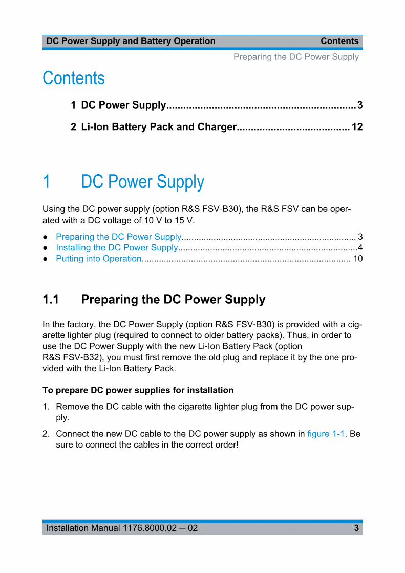
2. Connect the new DC cable to the DC power supply as shown in figure 1-1. Besure to connect the cables in the correct order!
Preparing the DC Power Supply
DC Power SupplyDC Power Supply and Battery Operation
4Installation Manual 1176.8000.02 ─ 02
Fig. 1-1: Connecting the new DC power cable to the DC power supply
Blue = - terminalBrown = + terminal
1.2 Installing the DC Power Supply
The DC power supply is attached to the rear panel of the R&S FSV.
To install the DC Power Supply on the R&S FSV
1. Disconnect the power cable from the R&S FSV.
2. Only for instruments with R&S FSV‑B1 option (ruggedized housing):
Installing the DC Power Supply
DC Power SupplyDC Power Supply and Battery Operation
5Installation Manual 1176.8000.02 ─ 02
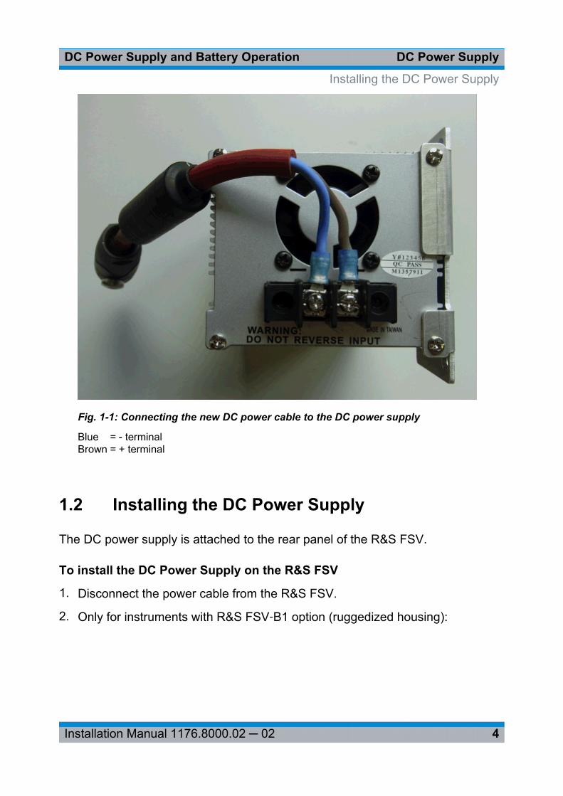
a) Unscrew and remove the corner protectors (1).
Fig. 1-2: Removing corner protectors
Installing the DC Power Supply
DC Power SupplyDC Power Supply and Battery Operation
6Installation Manual 1176.8000.02 ─ 02
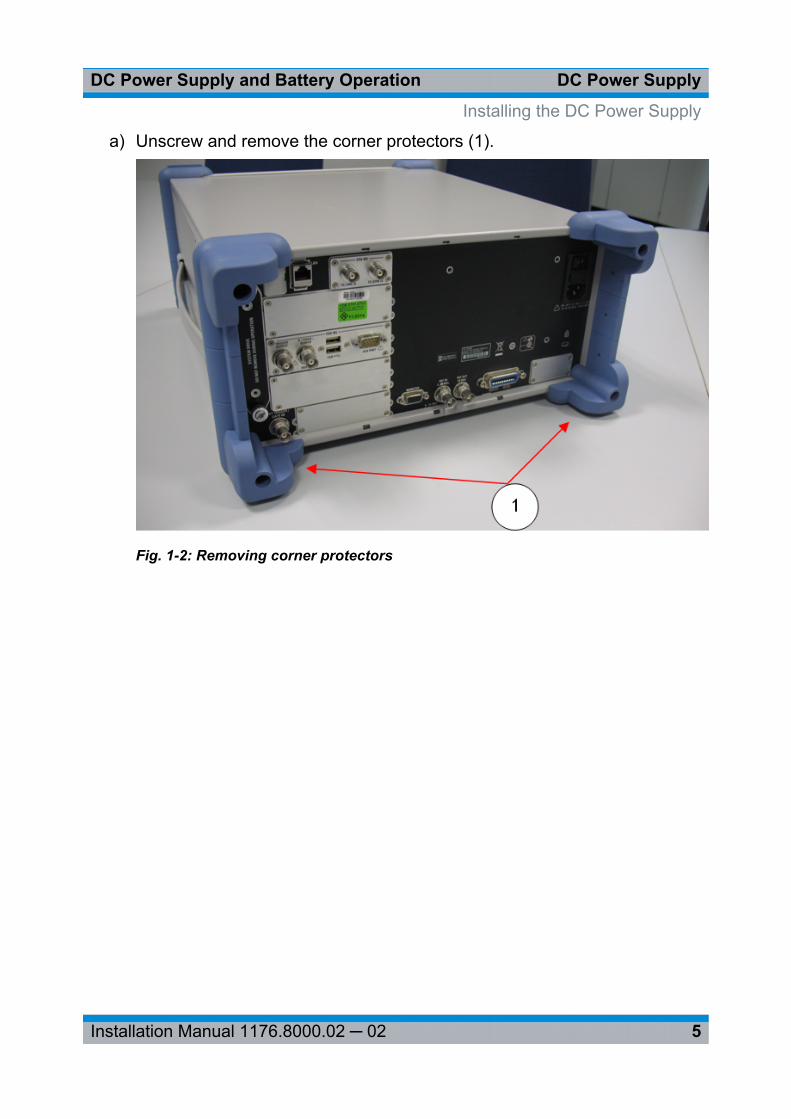
b) Screw in the pins (2).
Fig. 1-3: Screwing in pins
Installing the DC Power Supply
DC Power SupplyDC Power Supply and Battery Operation
7Installation Manual 1176.8000.02 ─ 02
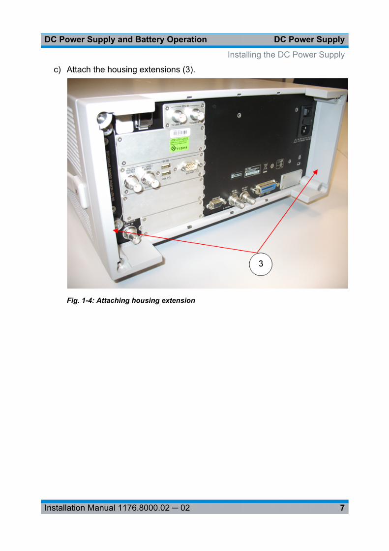
c) Attach the housing extensions (3).
Fig. 1-4: Attaching housing extension
Installing the DC Power Supply
DC Power SupplyDC Power Supply and Battery Operation
8Installation Manual 1176.8000.02 ─ 02
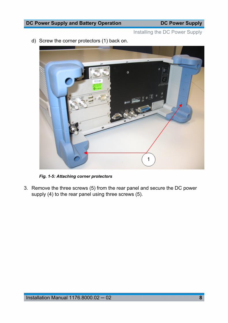
d) Screw the corner protectors (1) back on.
Fig. 1-5: Attaching corner protectors
3. Remove the three screws (5) from the rear panel and secure the DC powersupply (4) to the rear panel using three screws (5).
Installing the DC Power Supply
DC Power SupplyDC Power Supply and Battery Operation
9Installation Manual 1176.8000.02 ─ 02
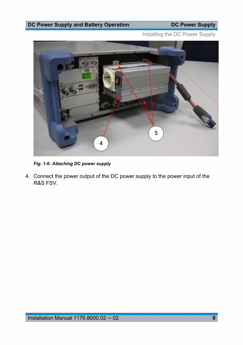
Fig. 1-6: Attaching DC power supply
4. Connect the power output of the DC power supply to the power input of theR&S FSV.
Installing the DC Power Supply
DC Power SupplyDC Power Supply and Battery Operation
10Installation Manual 1176.8000.02 ─ 02
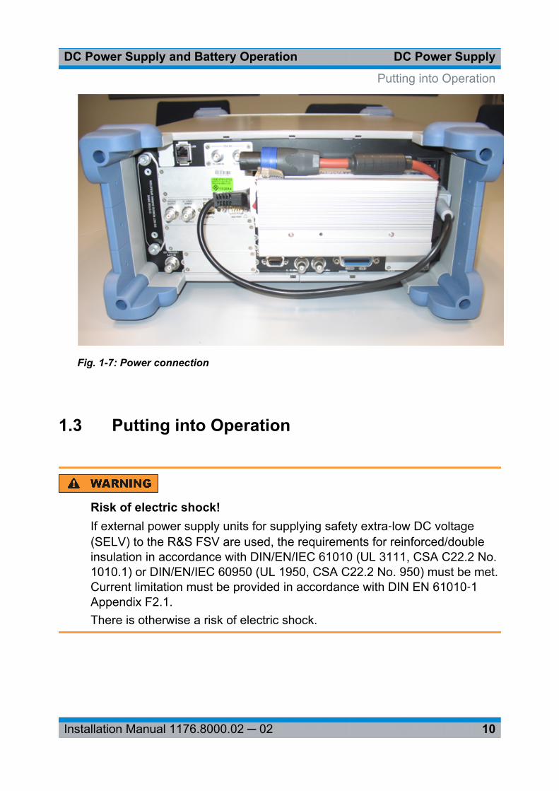
Fig. 1-7: Power connection
1.3 Putting into Operation
Risk of electric shock!If external power supply units for supplying safety extra‑low DC voltage(SELV) to the R&S FSV are used, the requirements for reinforced/doubleinsulation in accordance with DIN/EN/IEC 61010 (UL 3111, CSA C22.2 No.1010.1) or DIN/EN/IEC 60950 (UL 1950, CSA C22.2 No. 950) must be met.Current limitation must be provided in accordance with DIN EN 61010‑1Appendix F2.1.There is otherwise a risk of electric shock.
Putting into Operation
DC Power SupplyDC Power Supply and Battery Operation
11Installation Manual 1176.8000.02 ─ 02
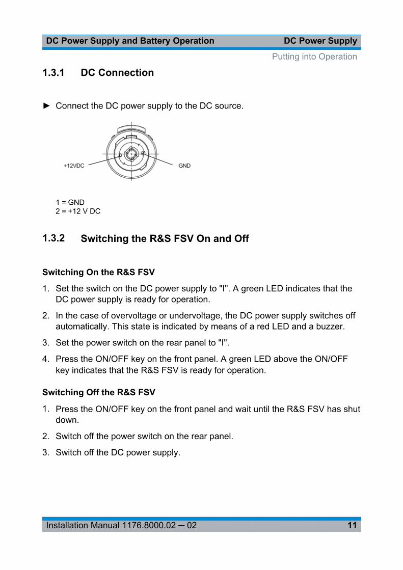
1.3.1 DC Connection
► Connect the DC power supply to the DC source.
1 = GND2 = +12 V DC
1.3.2 Switching the R&S FSV On and Off
Switching On the R&S FSV
1. Set the switch on the DC power supply to "I". A green LED indicates that theDC power supply is ready for operation.
2. In the case of overvoltage or undervoltage, the DC power supply switches offautomatically. This state is indicated by means of a red LED and a buzzer.
3. Set the power switch on the rear panel to "I".
4. Press the ON/OFF key on the front panel. A green LED above the ON/OFFkey indicates that the R&S FSV is ready for operation.
Switching Off the R&S FSV
1. Press the ON/OFF key on the front panel and wait until the R&S FSV has shutdown.
2. Switch off the power switch on the rear panel.
3. Switch off the DC power supply.
Putting into Operation
Li-Ion Battery Pack and ChargerDC Power Supply and Battery Operation
12Installation Manual 1176.8000.02 ─ 02
2 Li-Ion Battery Pack and ChargerWith the Li‑ion battery pack (option R&S FSV‑B32), the R&S FSV together withthe DC power supply (R&S FSV‑B30) can be operated independently of an ACpower supply. The R&S FSV‑B32 option contains 4 Li‑ion rechargeable batteries.
The rechargeable batteries can be charged externally using the R&S FSV‑B34charger.
2.1 Installing the Battery Pack
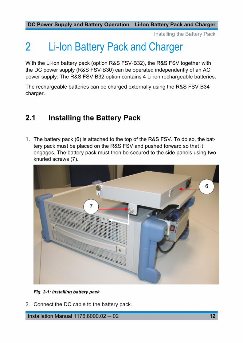
1. The battery pack (6) is attached to the top of the R&S FSV. To do so, the bat-tery pack must be placed on the R&S FSV and pushed forward so that itengages. The battery pack must then be secured to the side panels using twoknurled screws (7).
Fig. 2-1: Installing battery pack
2. Connect the DC cable to the battery pack.
Installing the Battery Pack
Li-Ion Battery Pack and ChargerDC Power Supply and Battery Operation
13Installation Manual 1176.8000.02 ─ 02
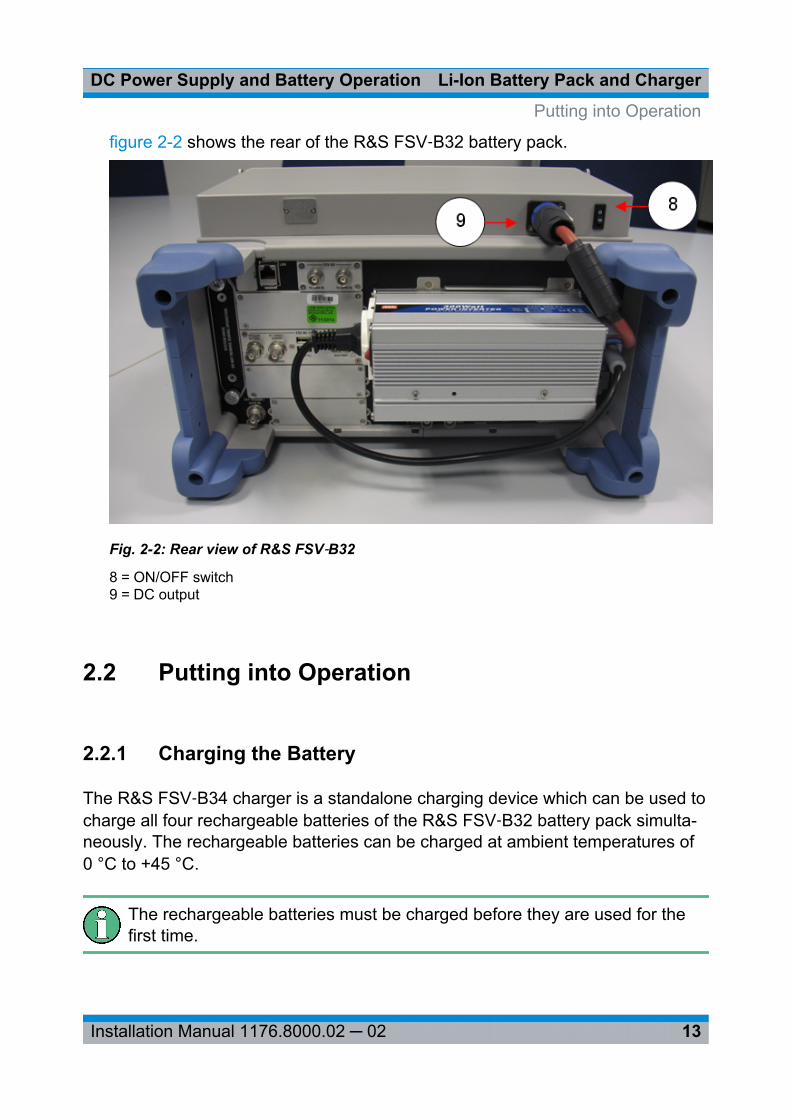
figure 2-2 shows the rear of the R&S FSV‑B32 battery pack.
Fig. 2-2: Rear view of R&S FSV‑B32
8 = ON/OFF switch9 = DC output
2.2 Putting into Operation
2.2.1 Charging the Battery
The R&S FSV‑B34 charger is a standalone charging device which can be used tocharge all four rechargeable batteries of the R&S FSV‑B32 battery pack simulta-neously. The rechargeable batteries can be charged at ambient temperatures of0 °C to +45 °C.
The rechargeable batteries must be charged before they are used for thefirst time.
Putting into Operation
Li-Ion Battery Pack and ChargerDC Power Supply and Battery Operation
14Installation Manual 1176.8000.02 ─ 02
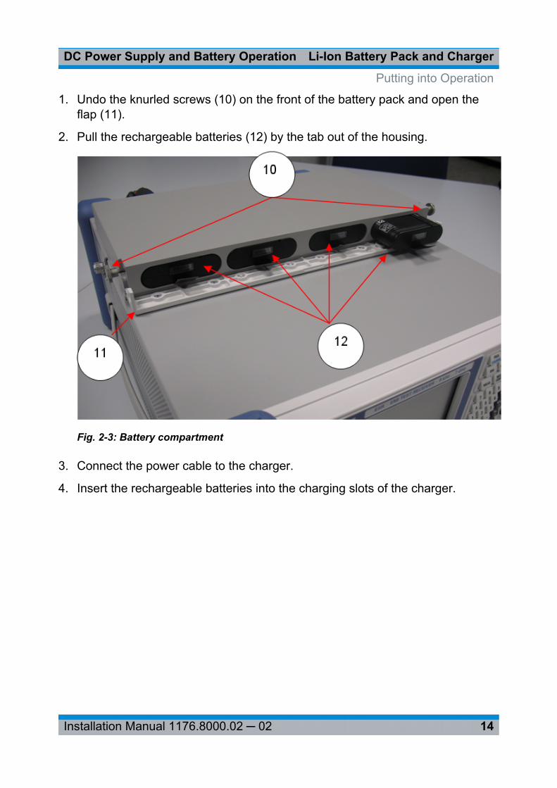
1. Undo the knurled screws (10) on the front of the battery pack and open theflap (11).
2. Pull the rechargeable batteries (12) by the tab out of the housing.
Fig. 2-3: Battery compartment
3. Connect the power cable to the charger.
4. Insert the rechargeable batteries into the charging slots of the charger.
Putting into Operation
Li-Ion Battery Pack and ChargerDC Power Supply and Battery Operation
15Installation Manual 1176.8000.02 ─ 02
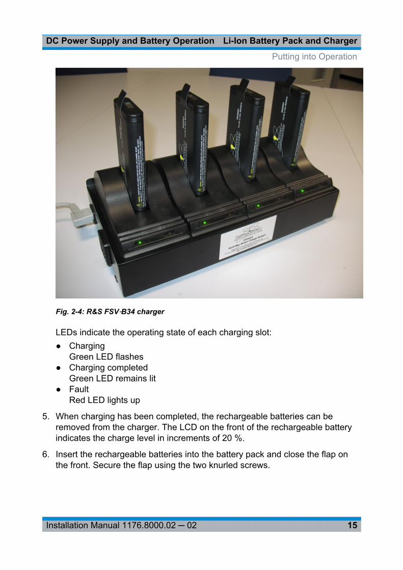
Fig. 2-4: R&S FSV‑B34 charger
LEDs indicate the operating state of each charging slot:● Charging
Green LED flashes● Charging completed
Green LED remains lit● Fault
Red LED lights up
5. When charging has been completed, the rechargeable batteries can beremoved from the charger. The LCD on the front of the rechargeable batteryindicates the charge level in increments of 20 %.
6. Insert the rechargeable batteries into the battery pack and close the flap onthe front. Secure the flap using the two knurled screws.
Putting into Operation
Li-Ion Battery Pack and ChargerDC Power Supply and Battery Operation
16Installation Manual 1176.8000.02 ─ 02
2.2.2 Switching the R&S FSV On and Off
Switching On the R&S FSV
1. Set the switch on the battery pack to "I".
2. Set the switch on the DC power supply to "I". A green LED indicates that theDC power supply is ready for operation.
3. In the case of undervoltage, the DC power supply switches off automatically.This state is indicated by means of a red LED and a buzzer.
4. Set the power switch on the rear panel to "I".
5. Press the ON/OFF key on the front panel. A green LED above the ON/OFFkey indicates that the R&S FSV is ready for operation.
Switching Off the R&S FSV
1. Press the ON/OFF key on the front panel and wait until the R&S FSV has shutdown.
2. Switch off the power switch on the rear panel.
3. Switch off the DC power supply.
4. Switch off the battery pack.
Putting into Operation

![ELECTRICAL & POWER CONTROL PGB A - NICOclub < component diagnosis > [power supply&ground circuit] power supply routing circuit wiring diagram - battery power supply fuse no](https://img.pdfslide.net/doc/110x75/610d80e95794fd494a1bc426/electrical-power-control-pgb-a-nicoclub-component-diagnosis-power.jpg)