Embed Size (px)
Citation preview
UNCLASSIFIED
Defense Technical Information CenterCompilation Part Notice
ADPO10508TITLE: Aspects of Aerodynamic Optimization forMilitary Aircraft Design
DISTRIBUTION: Approved for public release, distribution unlimited
This paper is part of the following report:
TITLE: Aerodynamic Design and Optimisation ofFlight Vehicles in a Concurrent
Multi-Disciplinary Environment [la Conception etl'optimisation aerodynamiques des vehiculeseriens dans un environnement pluridisciplinaire
et simultane]
To order the complete compilation report, use: ADA388284
The component part is provided here to allow users access to individually authored sections
f proceedings, annals, symposia, ect. However, the component should be considered within
he context of the overall compilation report and not as a stand-alone technical report.
The following component part numbers comprise the compilation report:
ADP010499 thru AI W3SSIFIED
11-1
Aspects of Aerodynamic Optimisation for Military Aircraft DesignB. Probert
Aerodynamics Department, British AerospaceMilitary Aircraft & Aerostructures
Building W427D, Warton AerodromePreston, Lancashire PR4 lAX, United Kingdom
1 Summary performance and structural optimisation is weak. The former
usually optimises a camber / twist distribution for a given wing
The paper considers the role of various optimisation strategies overall thickness distribution, whilst the latter depends
in the aerodynamic design of military combat aircraft. dominantly on the thickness. The twist requirement willinfluence the wing structural optimisation but on military
The multi - design point targets of military aircraft implies that aircraft this requirement may be dominated by other
the final product must achieve a carefully judged balance considerations of controllability, in particular achieving high
between, often conflicting, requirements. The current levels of roll rate at high speed.
established way of working to achieve this 'balance' is firstreviewed including the use of rule based procedures, the The wider optimisation issues for overall thickness, camberapplication of linearised CFD codes in both direct and and twist design, particularly for supersonic performance has a
inverse/optimisation modes, and the role of initial experimental strong link with structural optimisation and is an area which
data leading on to more detailed CFD work and experimental should benefit from MDO techniques.verification. Practical examples are given relating to the designof various projects including the Experimental Aircraft Following the examples mentioned above the need for change
Programme (EAP), which was the forerunner of Eurofighter. is considered and means of achieving these is proposed. In thiscontext, it is emphasised that not only increased automation
The need for improvements is identified, being primarily and concurrency of existing methods are required but also
brought about by considerations of affordability and reduced there is a need to change the fundamental processes. It should
design cycle time and also by the challenge posed from novel be noted that the word 'change' is used, rather than 'improve',
configurations to met low observability requirements. The when considering an individual process. This reflects the
means of achieving these improvements is discussed, and these increasing emphasis on affordability and reduction in designimply the development of Multi Disciplinary Optimisation cycle time - not always compatible with quality improvements,
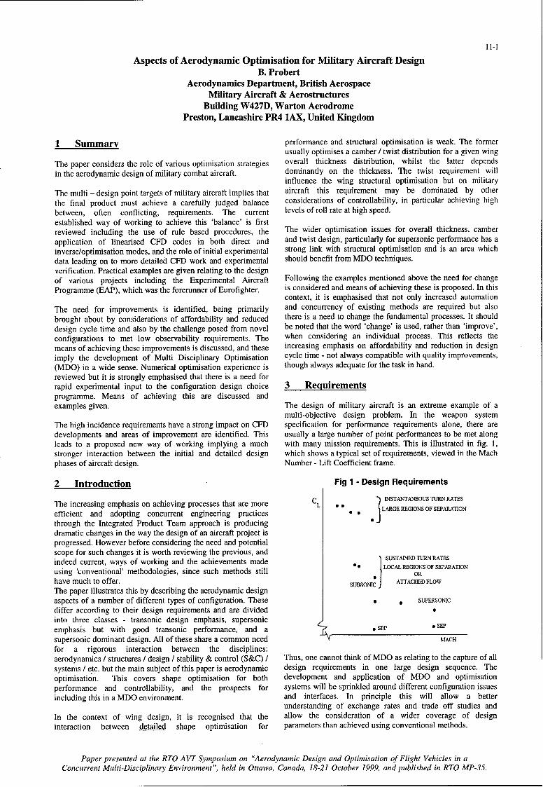
(MDO) in a wide sense. Numerical optimisation experience is though always adequate for the task in hand.reviewed but it is strongly emphasised that there is a need forrapid experimental input to the configuration design choice 3 Reiuirementsprogramme. Means of achieving this are discussed andexamples given. The design of military aircraft is an extreme example of a
multi-objective design problem. In the weapon systemThe high incidence requirements have a strong impact on CFD specification for performance requirements alone, there aredevelopments and areas of improvement are identified. This usually a large number of point performances to be met alongleads to a proposed new way of working implying a much with many mission requirements. This is illustrated in fig. 1,stronger interaction between the initial and detailed design which shows a typical set of requirements, viewed in the Machphases of aircraft design. Number - Lift Coefficient frame.
2 Introduction Fig 1 - Design Requirements
The increasing emphasis on achieving processes that are more CL LARGE REGIONS OF SEPARATION
efficient and adopting concurrent engineering practices INSTANAEONO RATES
through the Integrated Product Team approach is producing .
dramatic changes in the way the design of an aircraft project isprogressed. However before considering the need and potentialscope for such changes it is worth reviewing the previous, andindeed current, ways of working and the achievements made LCSUSTARNED TURN RATESusing 'conventional' methodologies, since such methods still OR
have much to offer. UBSONIC J ATTACHED FLOWThe paper illustrates this by describing the aerodynamic designaspects of a number of different types of configuration. These SUPERSONIC
differ according to their design requirements and are dividedinto three classes - transonic design emphasis, supersonic SEP
emphasis but with good transonic performance, and a _ SEP
supersonic dominant design. All of these share a common need MACH
for a rigorous interaction between the disciplines:aerodynamics / structures / design / stability & control (S&C) / Thus, one cannot think of MDO as relating to the capture of allsystems / etc. but the main subject of this paper is aerodynamic design requirements in one large design sequence. Theoptimisation. This covers shape optimisation for both development and application of MDO and optimisationperformance and controllability, and the prospects for systems will be sprinkled around different configuration issuesincluding this in a MDO environment, and interfaces. In principle this will allow a better
understanding of exchange rates and trade off studies andIn the context of wing design, it is recognised that the allow the consideration of a wider coverage of designinteraction between detailed shape optimisation for parameters than achieved using conventional methods.
Paper presented at the RTO AVT Symposium on "Aerodynamic Design and Optimisation of Flight Vehicles in aConcurrent Multi-Disciplinary Environment", held in Ottawa, Canada, 18-21 October 1999, and published in RTO MP-35.
11-2
Even within the aerodynamic discipline itself there is a need to applicability. The above two examples of simple rules inbalance many related but conflicting requirements related to preliminary design will, if applied, lead to a configuration thatgeometry I flight condition clashes. This is the case for an needs thorough evaluation and that will usually needisolated wing - but in addition, there is a need to predict and substantial enhancement to achieve an adequate designallow for multi-component interference, e.g. wing - body standard.interaction in the initial stages of design. Thus, it is usually notpossible to think in terms of aerodynamic design for a wing in Fig 3 - Combination of Sweep and Thicknessisolation. In addition, as the design progresses the fullconfiguration will need to be evaluated using CFD and 70experimental facilities. C HORD.
SWEEP
At the project feasibility stage there is a need, on a military \ -project, to rapidly evaluate a large number of widely differentlayouts, in contrast to civil aircraft design where configuration NOZRO LT BUFFET ZERO LFT
changes tend to be perturbations of previous designs. Thisaspect has been compounded by the emphasis on achieving -. \.high standards of low observability leading to novel and non- C.ideal aerodynamic shapes, hence increasing the aerodynamic L\design challenge. _
Referring to fig. 1 it can be seen that the major part of theflight envelope implies the presence of mild or severe regions 5 TO CHoRAO
20
of separated flow. Consequently, there is a need to predict both
the onset of flow separation and the consequences on the 4.1 Transonic design case.configuration aerodynamics.
4.1.1 Thin Wing - supersonic performance as 'fallout'Finally, with all of the above in mind, there is a need toproduce the best 'balance' in the configuration to meet the The first example illustrates optimisation for a configurationabove objectives. with outstanding transonic flight performance using
supercritical wing technology allied with variable camber at4 Current means of achieving requirements the leading and trailing edge (Refs 1, 2).
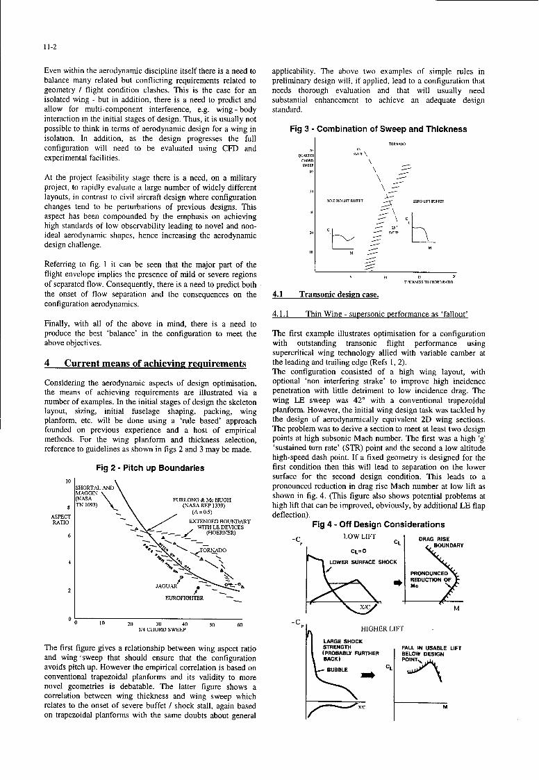
The configuration consisted of a high wing layout, withConsidering the aerodynamic aspects of design optimisation, optional 'non interfering strake' to improve high incidencethe means of achieving requirements are illustrated via a penetration with little detriment to low incidence drag. Thenumber of examples. In the initial stages of design the skeleton wing LE sweep was 420 with a conventional trapezoidallayout, sizing, initial fuselage shaping, packing, wing planform. However, the initial wing design task was tackled byplanform, etc. will be done using a 'rule based' approach the design of aerodynamically equivalent 2D wing sections.founded on previous experience and a host of empirical The problem was to derive a section to meet at least two designmethods. For the wing planform and thickness selection, points at high subsonic Mach number. The first was a high 'g'reference to guidelines as shown in figs 2 and 3 may be made. 'sustained turn rate' (STR) point and the second a low altitude
high-speed dash point. If a fixed geometry is designed for theFig 2 - Pitch up Boundaries first condition then this will lead to separation on the lower
surface for the second design condition. This leads to aSHORTAL.MD pronounced reduction in drag rise Mach number at low lift as(NA-GS FULN shown in fig. 4. (This figure also shows potential problems at(NASA FURLONG & Mc HUGHTN 1093) (NASA REP 1339) high lift that can be improved, obviously, by additional LE flap(A = 0.5) deflection).
ASPECTRATIO EXTENDED BOUNDARY Fig 4 - Off Design ConsiderationsTO WITH LE DEVICES
6--.. ." (HOERNER)6- -C LOW LIFT DRAG RISE
-cCL BOUNDARYA 11#4.O.~ - TORNADO
CL = 0. ..
S-, LOWER SURFACE SHOCKA.\ / PRONOUNCED
REDUCTION OF0
JAGUAR OI MD
EUROFIGHTER x -
0 Lo-CS 10 20 30 40 5(0 60 - HIP1.4 CHUoRL SWEEP HIGHER LIFT
LARGE SHOCKThe first figure gives a relationship between wing aspect ratio STRENGTH FALL IN USABLE LIFT
(PROBABLY FURTHER BELOW DESIGNand wing ;sweep that should ensure that the configuration BACK) POINTavoids pitch up. However the empirical correlation is based on BUBBLE CLconventional trapezoidal planforms and its validity to morenovel geometries is debatable. The latter figure shows acorrelation between wing thickness and wing sweep whichrelates to the onset of severe buffet / shock stall, again based ix/c Mon trapezoidal planforms with the same doubts about general
11-3
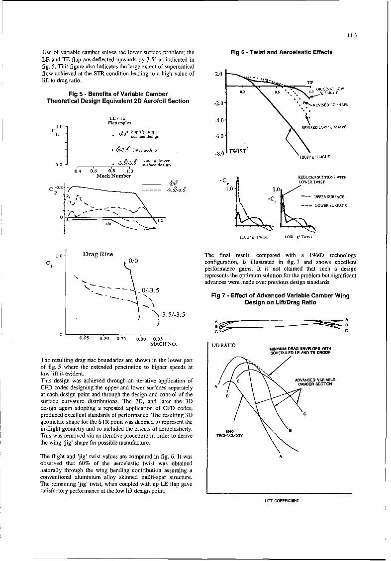
Use of variable camber solves the lower surface problem; the Fig 6 - Twist and Aeroelastic EffectsLE and TE flap are deflected upwards by 3.50 as indicated infig. 5. This figure also indicates the large extent of supercriticalflow achieved at the STR condition leading to a high value of 2.0lift to drag ratio. TIP
r O . 1 ;ý 0. 6RIGINAL LOW
Fig 5 - Benefits of Variable Camber 0.2 OR I • FGILrO
Theoretical Design Equivalent 2D Aerofoil Section 20 -REVISEO11O SHAPE
LE/TEFlap angles
\C1.0 REVISED LOW' g' SHAPECN. 0[o~ H-igh~ ' upper
N surlace design -6.0
S0/-3.?5 Intermediate _g.0 TWIST0 0Lo% 'g loerHIGH 'g' FLIGHTo5~ ~o Low ' g lower -. WS
0.0 .- 3.5/-3.5 surface design
0.4 0.6 0.8 1.0Mach Number REDUCED SUCTIONS WITH
O___ - CP LOWER TWIST
c -0.8-3.1.0 11.0,'I f P SURFACE
- - LOWER SURFACE
1.0 PR
-C
HIGH'g'TWIST LOW 'g'TWIST
1.0- Drag Rise The final result, compared with a 1960's technology"c 0/0 configuration, is illustrated in fig. 7 and shows excellent
L performance gains.: It is not claimed that such a design
represents the optimum solution for the problem but significantadvances were made over previous design standards.
S"Fig 7 - Effect of Advanced Variable Camber WingDesign on Lift/Drag Ratio
A A
B a
0 0.65 0.70 0.75 0.80 0.85MACH NO. LJD RATIO
MINIMUM DRAG ENVELOPE WITHSCHEDULED LE AND TE DROOP
The resulting drag rise boundaries are shown in the lower partof fig. 5 where the extended penetration to higher speeds atlow lift is evident.This design was achieved through an iterative application of ADVANCED VARIABLE
CFD codes designing the upper and lower surfaces separately A CAMBER SECI1ON
at each design point and through the design and control of thesurface curvature distributions. The 2D, and later the 3Ddesign again adopting a repeated application of CFD codes,produced excellent standards of performance. The resulting 3D /geometric shape for the STR point was deemed to represent thein-flight geometry and so included the effects of aeroelasticity. aThis was removed via an iterative procedure in order to derive TECHNOLOGY
the wing 'jig' shape for possible manufacture.
The flight and 'jig' twist values are compared in fig. 6. It was A
observed that 60% of the aeroelastic twist was obtainednaturally through the wing bending contribution assuming aconventional aluminium alloy skinned multi-spar structure.The remaining 'jig' twist, when coupled with up LE flap gavesatisfactory performance at the low lift design point.
LIFT COEFFICIENT
11-4
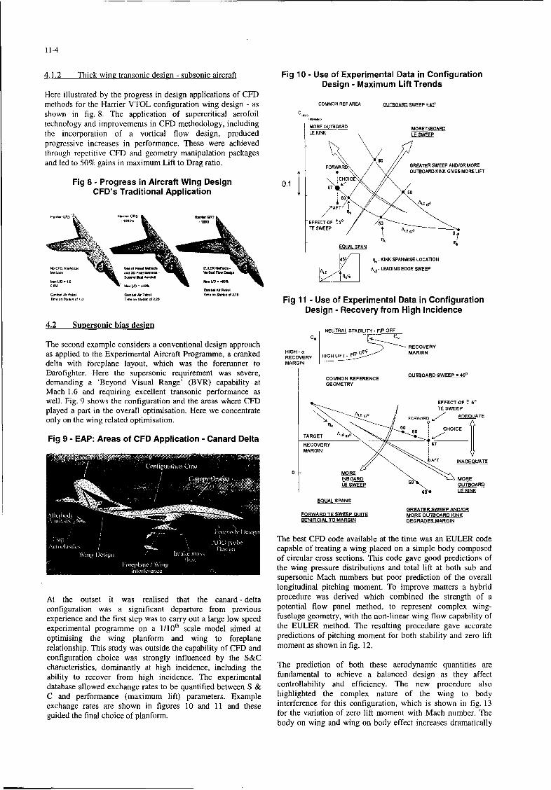
4.1.2 Thick wing transonic design - subsonic aircraft Fig 10 - Use of Experimental Data in ConfigurationDesign - Maximum Lift Trends
Here illustrated by the progress in design applications of CFDmethods for the Harrier VTOL configuration wing design - as COMMONREFAREA OUTBOARD $WEP=45'
shown in fig. 8. The application of supercritical aerofoil C•,,1technology and improvements in CFDT methodology, including MOREOUTBOARD MOREINBOARD
the incorporation of a vortical flow design, produced LE JNK LE SWEEP
progressive increases in performance. These were achievedthrough repetitive CFD and geometry manipulation packagesand led to 50% gains in maximum Lift to Drag ratio. FORWA GREATER SWEEP AND/OR MOREI " OUTBOARD KINK GIVES MOR LIFT
Fig 8 - Progress in Aircraft Wing Design 0.1 67 OI
CFD's Traditional Application I
,,OR
6,0
/AFT II.
M.II, GR3 '3MMR HTTý 51M
-IM EFFECT OF +5 5
TE SWEEP '1C,,T
EQUAL SPAN Ik
t50 KINK SPANWISE LOCATION
""W AR -ULRRMo M5W0.. I ALE. LEADING EDGE SWEEPNOF7 -- WR107 FARa Ddi -
.0 W.tJ = O H / = ý0%06M Wx UD = -,40%
C-mbd A Palmcf7,R M Rat r1t CORIRS MAFtAk TI " l Srlat l 1.75 Fig 11 - Use of Experimental Data in Configuration
Design - Recovery from High Incidence4.2 Supersonic bias design
NEUTRAL STABILITY. PIFP OFFC, C
The second example considers a conventional design approach RECOVERY
as applied to the Experimental Aircraft Programme, a cranked HIGH - MARGINRECOVERY HIG LIF-RGPINý
delta with foreplane layout, which was the forerunner to MARGIN
Eurofighter. Here the supersonic requirement was severe, OUTBOARD SWEEPR=oCOMMON REFERENCE
demanding a 'Beyond Visual Range' (BVR) capability at GEOMETRY
Mach 1.6 and requiring excellent transonic performance aswell. Fig. 9 shows the configuration and the areas where CFD EFFECT OFPt 5played a part in the overall optimisation. Here we concentrate LE SWEEP
only on the wing related optimisation.-FoRWAR Q ATARGET ALE ,0
Fig 9 - EAP: Areas of CFD Application - Canard Delta TARET--R-CRECOVERY •
MARGIN
bAFT INADEQUATE
I1NBOARD MORE
LE SWEEP ____.. 50 OUTBOARD
EQUAL SPANS
GREATER SWEEP AND/ORFORWARD TE SWEEP QUITE MORE OUTBOARD KINKBENIFICIAL TO MARGIN DEGRADES MARGIN
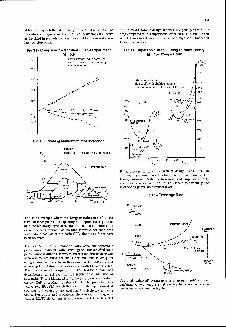
The best CFD code available at the time was an EULER codecapable of treating a wing placed on a simple body composedof circular cross sections. This code gave good predictions ofthe wing pressure distributions and total lift at both sub andsupersonic Mach numbers but poor prediction of the overalllongitudinal pitching moment. To improve matters a hybrid
At the outset it was realised that the canard - delta procedure was derived which combined the strength of aconfiguration was a significant departure from previous potential flow panel method, to represent complex wing-experience and the first step was to carry out a large low speed fuselage geometry, with the non-linear wing flow capability ofexperimental programme on a 1/10th scale model aimed at the EULER method. The resulting procedure gave accurateoptimising the wing planform and wing to foreplane predictions of pitching moment for both stability and zero liftrelationship. This study was outside the capability of CFD and moment as shown in fig. 12.configuration choice was strongly influenced by the S&Ccharacteristics, dominantly at high incidence, including the The prediction of both these aerodynamic quantities areability to recover from high incidence. The experimental fundamental to achieve a balanced design as they affectdatabase allowed exchange rates to be quantified between S & controllability and efficiency. The new procedure alsoC and performance (maximum lift) parameters. Example highlighted the complex nature of the wing to bodyexchange rates are shown in figures 10 and 11 and these interference for this configuration, which is shown in fig. 13guided the final choice of planform. for the variation of zero lift moment with Mach number. The
body on wing and wing on body effect increases dramatically
11-5
at transonic speeds though the wing alone trend is benign. The even a mild transonic design suffers a 4% penalty in zero liftprocedure also agrees well with the experimental data shown drag compared with a supersonic design case. The final designas the filled in symbols and was thus used to design and assess selected was based on a refinement of a supersonic linearisedlater developments, theory optimisation.
Fig 12 - Comparison - Modified Euler v Experiment Fig 14- Supersonic Drag - Lifting Surface TheoryM = 0.9 M = 1.4 Wing + Body
C EULER THEORY SIMPLE BODYL 0 0
EULER WING WITH 'PANEL' BODY A S LE _TEEXPERIMENT 0 -6/-6
0.8
.009
0.6 Showing variationdue to lift with pitching moment .008
for combinations of L.E. and T.E. flaps 6/-60.4C=
0.12 1 007TE flp-41-40.2
.0061 C = 0.0 . MildTranso c/= 0Design .006
.- -. Q ... . _ 4 ,05 6 .0 8 .0 IX 1 0 .0 .0 0 5 " .O 8 2 .0 0 50
/0
-0.04 .004 Mild Transonic. o
.003 . ,-61-6 0Fig 13- Pitching Moment at Zero Incidence -0 60
o2
• t / 4% of a/c.,° -.EAP supersonicTH EO RY 001 ] • -2/-. .. drag .001
C~• -2/-2E -/-
CM I ~~PANEL METHOD AND EULER FOR WING SproiMCM CM
-EXPERIMENTBODY N___By a process of repetitive manual design using CFD an
exchange rate was derived between wing maximum camber0.01 levels, subsonic STR performance and supersonic 'Ig'•_• " performance as shown in fig. 15. This served as a useful guide
, Bdy.. . in checking permissible camber levels.
-- •," [•T-[['7:Xl•Fig 15 -Exchange Rate
C-
eL=0.05@M=l.4O0.006 -This is an example where the designer makes use of, at the
time, an inadequate CFD capability but improvises to produce___an effective design procedure. Had an automatic optimisation 0.004- DESIGNw WINcapability been available at the time it would not have been
Supersonic
C,~~~ PAEeMTODADaltyFR IG i
successful since use of the basic CFD alone would not havebeen adequate. 0.002-ihl •Sc 8he u eThe search for a configuration with excellent supersonic cam bperformance coupled with very good transonic/subsonic p 1% m2% Caxm
performance is difficult. It was found that the best balance was 100 gu iOdeachieved by designing for the supersonic manoeuvre point CD•,•s -10%using a combination of linear theory and an EULER code and Gauboicachieving the sub/transonic performance with LE and TE flap. @M-o.9o 2%Wn0EI NWNThe alternative of designing for the transonic case and cL--O• -0 % Limiting-"decambering to achieve the supersonic case was not as Camber
successful. This is illustrated in fig. 14 for the early work doneon the EAP at a Mach number of 1.4. The predicted drag The final 'balanced' design gave large gains in sub/transonicvalues (via EULER) are plotted against pitching moment at performance with only a small penalty to supersonic cruisetwo constant values of lift coefficient, effectively allowing performance as shown in fig. 16.comparison at trimmed conditions. The variation in drag withvarious LEITE deflections is also shown and it is clear that
11-6
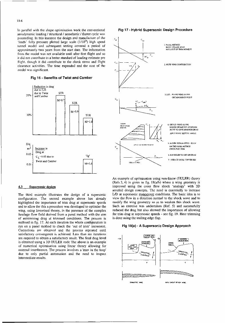
In parallel with the shape optimisation work the conventional Fig 17 - Hybrid Supersonic Design Procedureaerodynamic loading / structural / aeroelastic / flutter cycle wasproceeding. In this instance the design and manufacture of the C'loads' fully pressure plotted large scale ( 1/ 1 0 th) high speed LDtunnel model and subsequent testing covered a period of I.BPOADNE MTHOD
approximately two years from the start date. The information NOTE OUT OF TRIM MOMENT
from the model was not available until after first flight and so CLit did not contribute to a better standard of loading estimate preCflight, though it did contribute to the check stress and flight cC-clearance activities. The time expended and the cost of the '2. NOTE WING CONTRIBUTION
model was significant. e.
Fig 16 - Benefits of Twist and Camber
Reduction in dragdue to Liftdue to Twist STR
20%' and Camber 3. LIT - PLANE WINO ALONE
OBTAIN DESIGN POINT
STR AC),
10% W09 STR
10%. C L 4. OBTAIN WING ALONE
DESIGN GEOMETRY AT DESIGNPOINT TO GIVE MIMIMUM DRAG
APPLY BODY SETTING ANGLE
D/q ,5. RERUN DESIGN WING + BODY
c ON THiE PANEL METHOD
m2
Increase in CHECK FOR TRIM0.2 Drag at 1
0.02- de ato l 6. RUN EULER TO OBTAIN DRAG
Twist and Camber 7 ITERATE UNTIL CONV¢ERGED
0.01 Twist=and1Camber
An example of optimisation using non-linear (EULER) theory(Refs 3, 4) is given in fig. 18(a/b) where a wing geometry is
4.3 Supersonic design improved using the cross flow shock 'analogy' with 2Daerofoil design concepts. The need is essentially to increase
The third example illustrates the design of a supersonic LID at supersonic manoeuvre conditions. The basic idea is toconfiguration. The second example above has already view the flow in a direction normal to the shock wave and tohighlighted the importance of trim drag at supersonic speeds modify the wing geometry so as to weaken this shock wave.and to allow for this a procedure was developed to optimise the Such an exercise was undertaken (Ref. 5) and successfullywing, using linearised theory, in the presence of the complex reduced the drag but also showed the importance of allowingfuselage flow field derived from a panel method with the aim for trim drag at supersonic speeds - see fig. 19. Here trimmingof minimising drag at trimmed conditions. The process is is done using the trailing edge flap.outlined in fig. 17. At each iteration the whole configuration isrun on a panel method to check the 'out of trim' increment. Fig 18(a) - A Supersonic Design ApproachCorrections are obtained and the process repeated untilsatisfactory convergence is achieved. Less than six iterationsare required to obtain a satisfactory result. The final drag level -c,
is obtained using a 3D EULER code The above is an exampleof numerical optimisation using linear theory allowing forexternal interference. The process involves a 'man in the loop'due to only partial automation and the need to inspect _ ,intermediate results.
SYMhMETRC WTE5 NON-LIIEAP OES6N WING
11-7
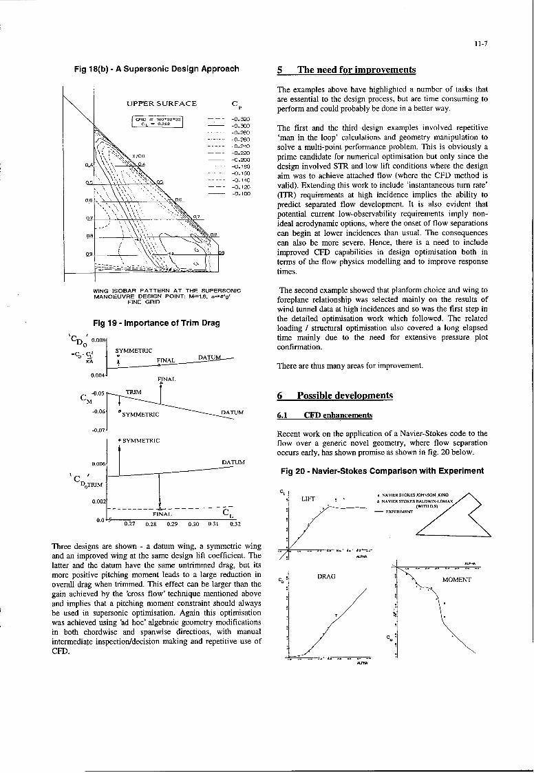
Fig 18(b) - A Supersonic Design Approach 5 The need for improvements
The examples above have highlighted a number of tasks that
UPPER SURFACE C are essential to the design process, but are time consuming toperform and could probably be done in a better way.
GR.ID .16032321 - -0o320-o.IL The first and the third design examples involved repetitivei.-.•:. ... .o 2eo
-....- 0.260 'man in the loop' calculations and geometry manipulation toS,-,-0.240 solve a multi-point performance problem. This is obviously aX, •? ',-. Co -0.220
-0.2W prime candidate for numerical optimisation but only since the\,\ -0o.10 design involved STR and low lift conditions where the design
,- . . aim was to achieve attached flow (where the CFD method is" ". 05' -,-'.-"".-O -0. 140
-0.120 valid). Extending this work to include 'instantaneous turn rate'0_,_,," . -,6 (ITR) requirements at high incidence implies the ability to
predict separated flow development. It is also evident thatpotential current low-observability requirements imply non-ideal aerodynamic options, where the onset of flow separations
o8 o can begin at lower incidences than usual. The consequencescan also be more severe. Hence, there is a need to includeimproved CFD capabilities in design optimisation both interms of the flow physics modelling and to improve responsetimes.
WING ISOBAR PATTERN AT THE SUPERSONIC The second example showed that planform choice and wing toMANOEUVRE DESIGN POINT: M=1.6, n=4'g'
FINE GRID foreplane relationship was selected mainly on the results ofwind tunnel data at high incidences and so was the first step in
Fig 19 - Importance of Trim Drag the detailed optimisation work which followed. The relatedloading I structural optimisation also covered a long elapsed
'CD' 0.008 time mainly due to the need for extensive pressure plot
SYMMETRIC confirmation.
INL DATUMfa There are thus many areas for improvement.
0.004FINAL
CM-0.05 TRIM 6 Possible developments
-0.06 r SYMMETRIC DUM 6.1 CFD enhancements
SYMMTI Recent work on the application of a Navier-Stokes code to theSYMMETRIC flow over a generic novel geometry, where flow separation
toccurs early, has shown promise as shown in fig. 20 below.0.006 . DATUM
SC 'Fig 20 - Navier-Stokes Comparison with ExperimentDoTRIM
CL * NAVIER STOKES JOHNSON KING
0.002 LIFT A NAVIER STOKES BALDWIN-LOMAX
F--- L C EXPERIMENT
0.0 0.27 0.28 0.29 0.30 0.31 0.32
Three designs are shown - a datum wing, a symmetric wingand an improved wing at the same design lift coefficient. The 7!latter and the datum have the same untrimmed drag, but itsmore positive pitching moment leads to a large reduction in DRAG
C'. MOMENToverall drag when trimmed. This effect can be larger than the Cogain achieved by the 'cross flow' technique mentioned aboveand implies that a pitching moment constraint should alwaysbe used in supersonic optimisation. Again this optimisationwas achieved using 'ad hoc' algebraic geometry modificationsin both chordwise and spanwise directions, with manual Cintermediate inspection/decision making and repetitive use ofCFD.
11-8
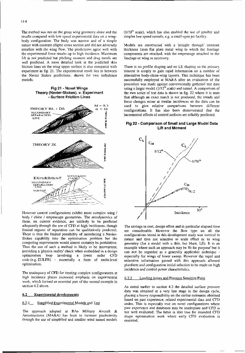
The method was run on the gross wing geometry alone and the ( 1/701h scale), which has also enabled the use of smaller andresults compared with low speed experimental data on a wing- simpler low speed tunnels, e.g. a small open jet facility.body configuration. The body was narrow and of a simplenature with constant elliptic cross section and did not adversely Models are constructed with a 'straight through' constantinterfere with the wing flow. The predictions agree well with thickness 1mm flat plate metal wing to which the fuselagethe experimental force results up to high incidence. Maximum components are attached, with the empennage attached to thelift is not predicted but pitching moment and drag trends are fuselage or wing as necessary.well predicted. A more detailed look at the predicted skinfriction lines on the wing upper surface is also compared with There is no profile shaping and no LE shaping so the primaryexperiment in fig. 21. The experimental result lies in between interest is simply to gain rapid information on a number ofthe Navier Stokes predictions, shown for two turbulence alternative body-chine-wing layouts. This technique has beenmodels. successfully employed at MA&A after an evaluation of the
procedure was made against conventionally gathered test dataFig 21 - Novel Wings using a larger model ( 1/12'h scale) and tunnel. A comparison of
Theory (Navier-Stokes). v. Experiment the two series of test data is shown in fig. 22 where it is seen- Surface Friction Lines that although an exact match is not produced, the trends and
force changes occur at similar incidences so the data can be4M = 0.3 used to give relative comparisons between different
THEORY BL + DS a = 10 configurations. It has also been demonstrated that theSECONDARYSEPARATION incremental effects of control surfaces are reliably predicted.
Fig 22 - Comparison of Small and Large Model DataLift and Moment
THEORYJK L CMe
CM ~CL
1/12/
/C 1/I70t
SEPAR EDEXPERIMENT FLOI /
SECONDARYNSEPARATION CM
LINE Z-4 I
VORT X p
However current configurations exhibit more complex wing ! Incidence 300
body / chine / empennage geometries. The aerodynamics ofthese, on current evidence, are unlikely to be predictedadequately through the use of CFD at high incidences, though The savings in cost, design effort and in particular elapsed timelimited regions of separation can be qualitatively predicted. are considerable. However the flow type on all theThere is thus the limited possibility of introducing a Navier- configurations tested in this development study was vortical inStokes capability into the optimisation problem but the nature and thus not sensitive to scale effect or to wingcomputing requirements would almost certainly be prohibitive, geometry (for a model with a thin, but blunt, LE). It is anThus the use of such a method is likely to be intermittent, example where such an approach may be 'fit for purpose' but itproviding a 'physics reality' check when embedded in a design can not be regarded as a generally applicable technique -optimisation loop involving a lower order CFD especially for wings of lower sweep. However the rapid andcode (e.g. EULER) - essentially a form of multi-level extensive information gained with this approach allowedoptimisation. planform and configuration initial selection to be made on high
incidence and control power characteristics.The inadequacy of CFD for treating complex configurations at
high incidence places increased emphasis on experimental 6.2.2 Loading issues and Pressure Sensitive Paintwork, which formed an essential part of the second example insection 4.2 above. As noted earlier in section 4.2 the detailed surface pressure
data was obtained at a very late stage in the design cycle,6.2 Experimental developments placing a heavy responsibility on the earlier estimates obtained
based on past experience, related experimental data and CFD6.2.1 Simplified Experimental Models and Test codes. This is especially true on novel configurations where
past experience and databases may be inadequate and CFD isThe approach adopted at BAe Military Aircraft & not well evaluated. The latter is also true for intended CFDAerostructures (MA&A) has been to increase productivity shape optimisation work where early CFD evaluation isthrough the use of simplified and smaller wind tunnel models essential.
11-9
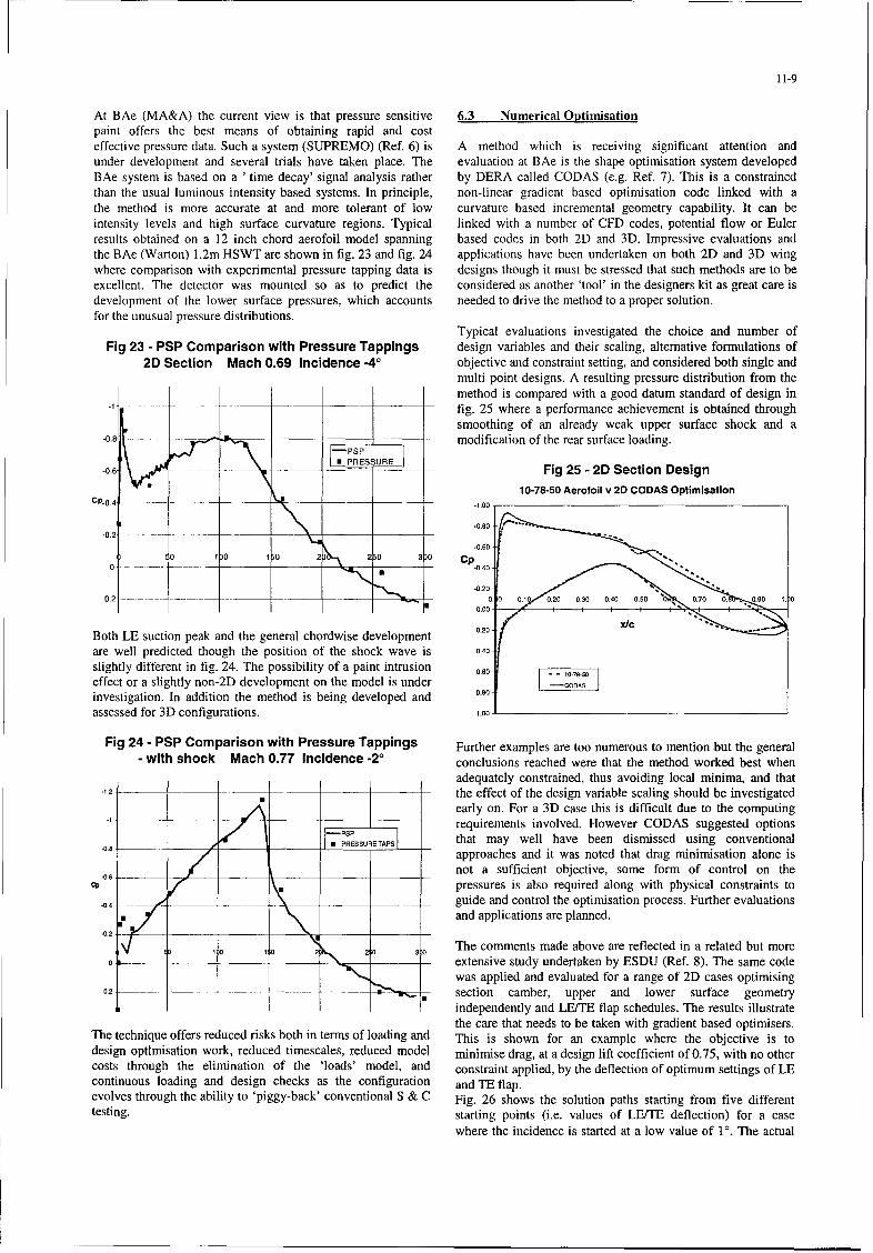
At BAe (MA&A) the current view is that pressure sensitive 6.3 Numerical Optimisationpaint offers the best means of obtaining rapid and costeffective pressure data. Such a system (SUPREMO) (Ref. 6) is A method which is receiving significant attention andunder development and several trials have taken place. The evaluation at BAe is the shape optimisation system developedBAe system is based on a ' time decay' signal analysis rather by DERA called CODAS (e.g. Ref. 7). This is a constrainedthan the usual luminous intensity based systems. In principle, non-linear gradient based optimisation code linked with athe method is more accurate at and more tolerant of low curvature based incremental geometry capability. It can beintensity levels and high surface curvature regions. Typical linked with a number of CFD codes, potential flow or Eulerresults obtained on a 12 inch chord aerofoil model spanning based codes in both 2D and 3D. Impressive evaluations andthe BAe (Warton) 1.2m HSWT are shown in fig. 23 and fig. 24 applications have been undertaken on both 2D and 3D wingwhere comparison with experimental pressure tapping data is designs though it must be stressed that such methods are to beexcellent. The detector was mounted so as to predict the considered as another 'tool' in the designers kit as great care isdevelopment of the lower surface pressures, which accounts needed to drive the method to a proper solution.for the unusual pressure distributions.
Typical evaluations investigated the choice and number ofFig 23 - PSP Comparison with Pressure Tappings design variables and their scaling, alternative formulations of
2D Section Mach 0.69 Incidence -40 objective and constraint setting, and considered both single andmulti point designs. A resulting pressure distribution from themethod is compared with a good datum standard of design in
.1 . . fig. 25 where a performance achievement is obtained throughsmoothing of an already weak upper surface shock and a
-0.8 .....-....- " ___PSP ] - modification of the rear surface loading.
-0.6 Is PRESSUR - Fig 25 - 2D Section Design
10-78-50 Aerofoil v 2D CODAS OptimisationCP-0.4 --------------. -1.00
.0.80-0 .2 . . .. ... . . . ....
)• ~-0.60•!0 10 10 2 250 3)0 Cp
0 ..... . . .__ ____ - -0.40
-0..200-2 ---- ~-~- ____ __________ 0. 0 0O .1 0.20 0.30 ý0.40 0.00 0.70 0. 0.00 1. 0
0.00 -
Both LE suction peak and the general chordwise development 0.20.
are well predicted though the position of the shock wave is 0.40.
slightly different in fig. 24. The possibility of a paint intrusion 0.60 - -
effect or a slightly non-2D development on the model is under I-CODAS _
investigation. In addition the method is being developed and 0.80
assessed for 3D configurations. 1.00
Fig 24 - PSP Comparison with Pressure Tappings Further examples are too numerous to mention but the general- with shock Mach 0.77 Incidence -20 conclusions reached were that the method worked best when
adequately constrained, thus avoiding local minima, and that-1.2 - the effect of the design variable scaling should be investigated
I early on. For a 3D case this is difficult due to the computing'1 .... requirements involved. However CODAS suggested options
.0.8 .... _ PRESSURETAPS that may well have been dismissed using conventionalapproaches and it was noted that drag minimisation alone is
___6 not a sufficient objective, some form of control on the- - pressures is also required along with physical constraints to
.04_ _ __ guide and control the optimisation process. Further evaluationsand applications are planned.
-0.0 2 20 3 The comments made above are reflected in a related but more0o, - extensive study undertaken by ESDU (Ref. 8). The same code
was applied and evaluated for a range of 2D cases optimising0.2 -- section camber, upper and lower surface geometry
independently and LE/TE flap schedules. The results illustratethe care that needs to be taken with gradient based optimisers.
The technique offers reduced risks both in terms of loading and This is shown for an example where the objective is todesign optlmisation work, reduced timescales, reduced model minimise drag, at a design lift coefficient of 0.75, with no othercosts through the elimination of the 'loads' model, and constraint applied, by the deflection of optimum settings of LEcontinuous loading and design checks as the configuration and TE flap.evolves through the ability to 'piggy-back' conventional S & C Fig. 26 shows the solution paths starting from five differenttesting. starting points (i.e. values of LB/TB deflection) for a case
where the incidence is started at a low value of 10. The actual
11-10
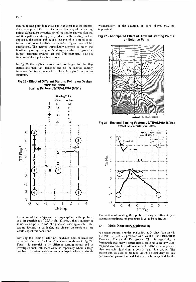
minimum drag point is marked and it is clear that the process visualisation' of the solution, as done above, may bedoes not approach the correct solution from any of the starting impractical.points. Subsequent investigation of the results showed that thesolution paths are strongly dependent on the scaling factors Fig 27 - Anticipated Effect of Different Starting Pointsapplied to the design and the fact that the initial starting point, on Solution Pathsin each case, is well outside the 'feasible' region (here, of liftcoefficient). The method immediately attempts to reach thefeasible region by changing the design variable that gives thelargest increment towards that end. This increment is also a 4
function of the input scaling factors. I
In fig. 26 the scaling factors used are larger for the flapdeflections than for incidence and so the method rapidly 3increases the former to reach the 'feasible region', but not anoptimum.
IFig 26 - Effect of Different Starting Points on Design
Variable PathsScaling Factors LE/TE/ALPHA (8/8/1)
Starting Point
LF Flop TE Flp
D 3.0 -2.0
X 0.4 0.5
3.0 4.0
+ -2.5 5.0 - 1 0 1 2 4
V -2.5 0.5
A -2.5 -2.0 Fig 28 - Revised Scaling Factors LEfTE/ALPHA (8/8/5)Effect on calculation paths
5 4 ........ ......... 0....... L --------- L - -- - - - V =0.02 eoce.p whrorenoted DIFTOI0.0 05
5 VMAX-Ot02 &0 4 ----- - - ------- ... .... •..... .w 0-..... . . . . i4 3 y . -- "• a=•O.02 00 O7
o 4
C', 3 - -'MAX=01 ~~~~~~. ........ .... . ..... . . .. ... .. ... ... .... . . . . . .
5 2 ½M I ; - ;;4 ... .... L .. . .......... ; ......... . . . . . . . . . . . . . .
0 5 - -1 -- .. . .. ... ....... ........ . . . . . . . . . .-- --- A
-2 6 - --- ----- -- -- -2 ----- S-2 )! ,. . . . .i ... .. ....... I-. . . . .
-3-3 -2 -1 0 1 2 3 4 -3 -
-3 -2 -1 0 1 2 3 4LE Flap LE Flap *
Inspection of the two-parameter design space for the problem The option of treating this problem using a different (e.g.
at a lift coefficient of 0.75 in fig. 27 shows that a number of stochastic) optimisation procedure is yet to be addressed
solutions are possible with the gradient based approach. If the 6.4 Multi-Disciplinary Optimisationscaling factors, in particular, are chosen appropriately onewould expect this behaviour. A system currently under evaluation at MA&A (Warton) is
FRONTIER (Ref. 9), produced as a result of the FRONTIERRevising the scaling factor on incidence does indicate the European Framework IV project. This is essentially a
expected behaviour for four of the cases, as shown in fig. 28. framework that allows distributed processing using any user-
Thus it is essential to try different starting points and to requre exctales Altrnate optimisin g a reinvetigte uchinfuenes arlyon speialy werea lrge required executables. Alternative optimisation packages are
investigate such influences early on especially where a large also available, including a genetic algorithm option. Thenumber of design variables are employed where a simple system can be used to produce the Pareto boundary for key
performance parameters and has already been applied by the
11-11
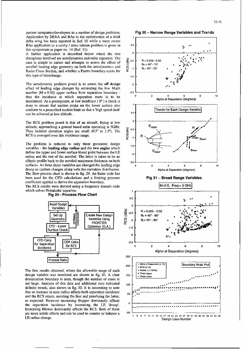
partner companies/developers to a number of design problems. Fig 30 - Narrow Range Variables and TrendsApplication by DERA and BAe to the optimisation of a thick 1delta wing has been reported in Ref. 10 while a more recentBAe application to a cavity / store release problem is given in 0.5 xx
this symposium as paper no. 14 (Ref. 11). xA further application is described below where the two 0 , x- x,
x x Xdisciplines involved are aerodynamics and radar signature. The - x xR. =, 0.X0
case is simple in nature and attempts to assess the effect of O0.5 R = 0.005-N0. kX:a Ou= 45'o.70' x . xg x xaerofoil leading edge geometry on both the aerodynamics and co _ eL=45o-70° x
Radar Cross Section, and whether a Pareto boundary exists for T x x
this type of interchange. -1.5 ' X
The aerodynamic problem posed is to assess the off design -2 xx
effect of leading edge changes by estimating the low Machnumber (M = 0.50) upper surface flow separation boundary - -2.5
thus the incidence at which separation starts is to be 0 2 4 6 8 10
maximised. As a prerequisite, at low incidence ( 00 ) a check is Alpha at Separation (degrees)
done to ensure that suction peaks on the lower surface also 1.. . .]
conform to a prescribed suction limit so that a 'high speed dash' ITrends for Each Design Varablecan be achieved at low altitude. 0.5
The RCS problem posed is that of an aircraft, flying at low oaltitude, approaching a ground based radar operating at 3GHz. 0upper RThus incident elevation angles are small (0.50 to 1.5). The ..
RCS is averaged over this incidence range. R) R rr eupper
The problem is reduced to only three geometric design 15
variables - the leading edge radius and the two angles whichdefine the upper and lower surface blend point between the LEradius and the rest of the aerofoil. The latter is taken to be anelliptic profile back to the aerofoil maximum thickness on both -2.__.
surfaces. As these three variables are changed the leading edge 0 2 4 6 8 10
droop or camber changes along with the curvature distribution. Alpha at Separation (degrees)The flow process chart is shown in fig. 29. An Euler code hasbeen used for the CFD calculations and a limiting pressure Fig 31 - Broad Range Variablescoefficient applied to derive the separation boundary.The RCS results were derived using a frequency domain code M=0.5, Frwhich solves Helmholtz' equation. 1
Fig 29 - Process Flow Chart0.5 X X
0 -, X XX X XlRead Design < 0 X S.Zx
I-Variables I2 X X' , X XX
SetUp Create New Design -4o.5 ,X XXGeometry Variables Using IO=45'-85' X Z X1 X, XX
8 FRONTIER I t) -1 GL=45o-85x-~we X : XVLrCFD Lower Optimiser (G.A.) -1 .5Surface Check Sur c1.5 wr
.2 § 8Sl -2.
I CFD Cac I E CIcs-.0for Separation for RCS 8 10S Incidence ]24681
Alpha at Separation (degrees)250[Process DataI
Alpha at Separation (x 10) Boundary Walk Plot200 RCS (x 10)F
The first results obtained, where the allowable range of each ,Radius (x 10000)Theta Upperdesign variable was restricted are shown in fig. 30. A clear 150 The Lower ..........
demarcation boundary is seen, though the number of cases is ,, a
not large. Analysis of this data and additional runs indicated 100 • * ....definite trends; also shown in fig. 30. It is interesting to note .Aaal alam:e.e e a.tt +,a99..... •that an increase in nose radius affects both separation incidence 50 . . .......... . .:...and the RCS return, assisting the first and penalising the latter, ++
as expected. However increasing @upper dominantly affectsthe separation incidence by increasing the LE 'droop'. 0Increasing Olower dominantly affects the RCS. Both of theseare more subtle effects and can be used to counter or balance a -50
1 3 5 7 9 11 13 15 17 19 21 23 25 27 29 31 33 35 37 39 41 43 45LE radius change. Design Case Number
11-12
Extending the allowable range of the design variables results in any optimisation or MDO system needs to capture thisthe fuller boundary of fig. 31, but there is still a clear Pareto component. As much of this is currently outside the scope ofboundary. Also shown in fig. 31 are the variations of the CFD there is a strong emphasis in developing a rapid means ofdesign variables along this boundary, with trends reflecting the obtaining experimental data, in order to bring this element intocomments made earlier. In particular the LE radius is allowed the MDO environment.to increase to improve the aerodynamic performance withoutmajor impact on the RCS. This is since the lower surface angle CFD plays a supporting role in the initial configuration studyis at its maximum and since the radar threat is from below, and this will increase as the methods are extensively evaluated
and/or the algorithms improve, and a leading role inThe above simple example has demonstrated the effectiveness identifying multi-component interference and furtherof the FRONTIER system to easily obtain trends, exchange downstream optimisation. The role of numerical optimisationrates and Pareto frontiers. However many more evaluations and MDO is currently more sound when viewed in the detailand applications of increasing complexity are necessary to design environment rather than the concept/feasibility stage,obtain a proper assessment. for military aircraft.
CFD enhancements, pressure sensitive paint and simplified
7 Future ways of working model build and testing techniques have been highlighted asthe means for progressing the design optimisation problem.
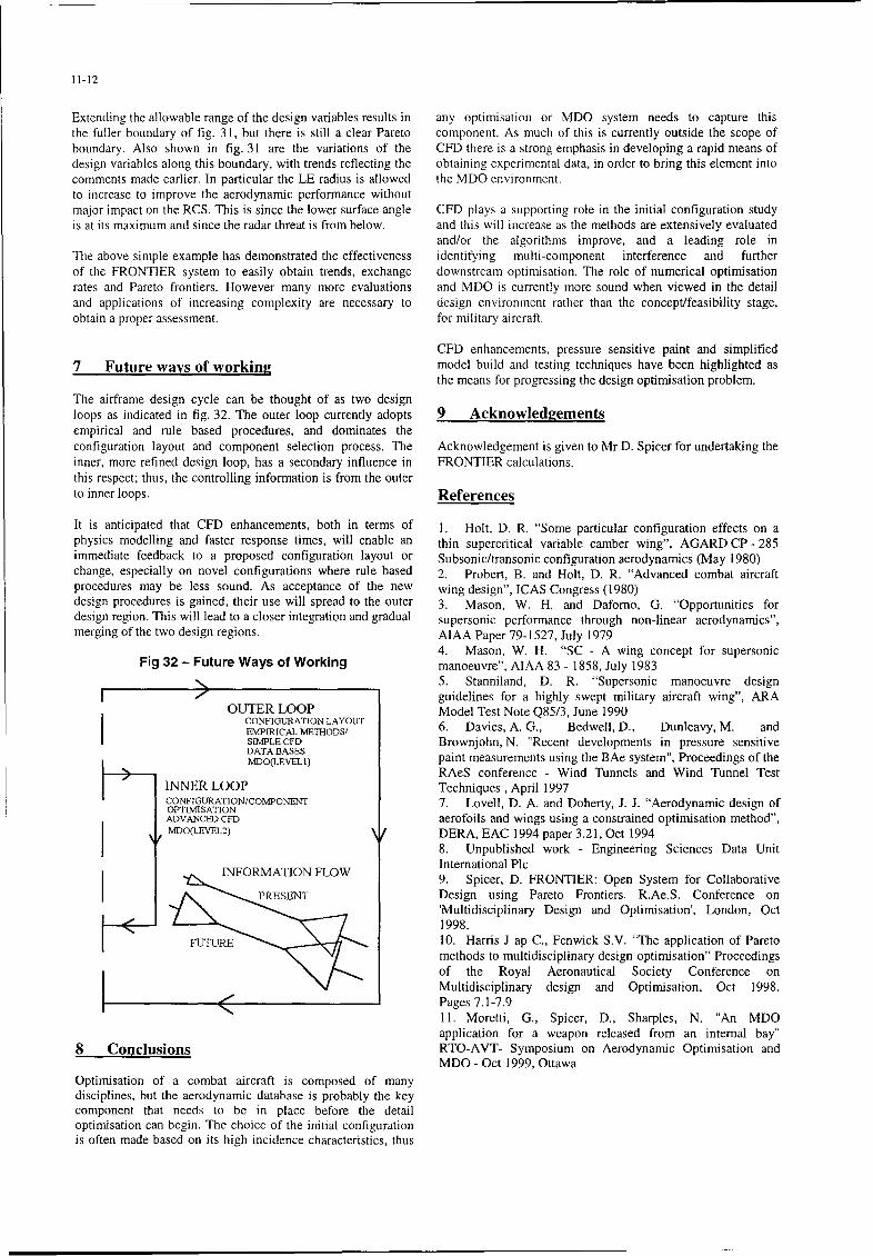
The airframe design cycle can be thought of as two designloops as indicated in fig. 32. The outer loop currently adopts 9 Acknowledgementsempirical and rule based procedures, and dominates theconfiguration layout and component selection process. The Acknowledgement is given to Mr D. Spicer for undertaking theinner, more refined design loop, has a secondary influence in FRONTIER calculations.this respect; thus, the controlling information is from the outerto inner loops. References
It is anticipated that CFD enhancements, both in terms of 1. Holt, D. R. "Some particular configuration effects on aphysics modelling and faster response times, will enable an thin supercritical variable camber wing", AGARD CP - 285immediate feedback to a proposed configuration layout or Subsonic/transonic configuration aerodynamics (May 1980)change, especially on novel configurations where rule based 2. Probert, B. and Holt, D. R. "Advanced combat aircraftprocedures may be less sound. As acceptance of the new wing design", ICAS Congress (1980)design procedures is gained, their use will spread to the outer 3. Mason, W. H. and Dafomo, G. "Opportunities fordesign region. This will lead to a closer integration and gradual supersonic performance through non-linear aerodynamics",merging of the two design regions. AIAA Paper 79-1527, July 1979
4. Mason, W. H. "SC - A wing concept for supersonicFig 32 - Future Ways of Working manoeuvre", AIAA 83 - 1858, July 1983
5. Stanniland, D. R. "Supersonic manoeuvre designI guidelines for a highly swept military aircraft wing", ARA
OUTER LOOP Model Test Note Q85/3, June 1990CONFIGURATION LAYOUT 6. Davies, A. G., Bedwell, D., Dunleavy, M. and
SIMPLE CFD Brownjohn, N. "Recent developments in pressure sensitiveDATA BASESMDO(LEVEL1) paint measurements using the BAe system", Proceedings of the
RAeS conference - Wind Tunnels and Wind Tunnel TestINNER LOOP Techniques, April 1997CONFIGURATION/COMPONENT 7. Lovell, D. A. and Doherty, J. J. "Aerodynamic design ofOPTIMISATIONADVAVCED CFD aerofoils and wings using a constrained optimisation method",MDO(LEVEL2) DERA, EAC 1994 paper 3.21, Oct 1994
8. Unpublished work - Engineering Sciences Data Unit
INFORMATION F W International Plc9. Spicer, D. FRONTIER: Open System for Collaborative
PRESEN Design using Pareto Frontiers. R.Ae.S. Conference on'Multidisciplinary Design and Optimisation', London, Oct
1998.SF7rURE 10. Harris J ap C., Fenwick S.V. "The application of Pareto
methods to multidisciplinary design optimisation" Proceedingsof the Royal Aeronautical Society Conference onMultidisciplinary design and Optimisation, Oct 1998.
< Pages 7.1-7.911. Moretti, G., Spicer, D., Sharples, N. "An MDOapplication for a weapon released from an internal bay"
8 Couclusions RTO-AVT- Symposium on Aerodynamic Optimisation andMDO - Oct 1999, Ottawa
Optimisation of a combat aircraft is composed of manydisciplines, but the aerodynamic database is probably the keycomponent that needs to be in place before the detailoptimisation can begin. The choice of the initial configurationis often made based on its high incidence characteristics, thus
![Defense Technical Information Center Compilation Part Noticedeveloped. In particular, research of Solovjev, V.K. [1934] indicated that physically strong soldiers with good cordial](https://img.pdfslide.net/doc/110x75/5e24b9bd62f9fc7dcd47e02b/defense-technical-information-center-compilation-part-notice-developed-in-particular.jpg)


![Defense Technical Information Center Compilation Part … militaires: Consommation actuelle, questions et strategies pour des options elargies] ... Biologic Effects of Adrenal Hormones](https://img.pdfslide.net/doc/110x75/5ae3820a7f8b9a5b348d84ce/defense-technical-information-center-compilation-part-consommation-actuelle.jpg)


![Defense Technical Information Center Compilation Part Notice · Capabilities of Military Aircraft, ... des vehicules terrestres et des vehicules maritimes] To order the complete compilation](https://img.pdfslide.net/doc/110x75/5b2560117f8b9a26578b485b/defense-technical-information-center-compilation-part-notice-capabilities-of.jpg)