Embed Size (px)
Citation preview
i R-71-1
TM FILE COEt
ESD ACCESSION LISJ TR1 Call Nn- /O A //*
Copy No. ^ of /"' ' c*3-
ESD RECORD COPY RETURN TO
SCIENTIFIC & TECHNICAL INFORMATION DIVISION
(TRI), Building 1210
Technical Note 1971-10
LES-8/9 Attitude Control System Numerical Simulation
C. H. Much N. P. Smith
F. W. Floyd
E. H. Swenson
5 February 1971
Division Contract F'19628-70-00230 by
Lincoln Laboratory MASSACHUSETTS INSTITUTE OF TECHNOLOGY
Lexington, Massachusetts •
A[)lz^U

Approved for public release; distribution unlimited.
MASSACHUSETTS INSTITUTE OF TECHNOLOGY
LINCOLN LABORATORY
LES-8/9 ATTITUDE CONTROL SYSTEM
NUMERICAL SIMULATION
C. H. MUCH
N. P. SMITH
Group 76
F. W. FLOYD
E. H. SWENSON
Group 63
TECHNICAL NOTE 1971-10
5 FEBRUARY 1971
Approved for public release; distribution unlimited.
LEXINGTON MASSACHUSETTS
The work reported in this document was performed at Lincoln Laboratory, a center for research operated by Massachusetts Institute of Technology, with the support of the Department of the Air Force under Contract F19628-70-C-0230.
This report may be reproduced to satisfy needs of U.S. Government agencies.
ABSTRACT
A program was written to simulate the three axis attitude control system
of LES-8/9. The underlying theory to the computer simulation and de-
tailed outlines of each of the subroutines involved in the complete program
are described.
Whenever feasible, the simulation was written to duplicate as closely as possible the logic and signal flow of the actual digital attitude control sys- tem. Each subroutine was thoroughly verified as accurate by independent
and integral system operation, as well as by theoretical estimates, analog computer simulations and actual experimental data.
A substantial compilation of data from this working program was catalogued and analyzed for attitude control system evaluation and optimization. This program also proved itself to be invaluable in the analysis of stability and performance of the complete attitude control system.
Accepted for the Air Force Joseph R. Waterman, Lt. Col., USAF Chief, Lincoln Laboratory Project Office
iii
CONTENTS
Abstract iii Nomenclature vi
I. Introduction I
II. System Equations 1
A. Euler Equations of Motion i
B. Euler Angle Transformations 2
C. Earth Sensor Measured Angles 2
D. Earth Sensor Simulation 2
III. Attitude Control Laws 3
A. Pitch Axis Control Modes 3
B. Pitch Axis Coarse Momentum Control 7
C. Roll Axis Control Modes 9
IV. Description of Simulation 11
A. Main Program of the Simulation 13
B. Major Subroutines 15
C. Output Format and Plotting Subroutines 2 3
V. Use of the Program 2 5
A. Input Variables 2 5
B. Output Data 27
Appendix 29
NOMENCLATURE
Z1'Z2'Z3
Y_
Y6
Y8
K qr
XJ,, XJ,, XJ, 1 Z 3
XJ. 4
M2, M3
IRNR
IRNP
LI, L2, L3
LSB
XD1 XD2 TD1, TD2, TD3
SIGMA
XP1, XP2, NP XK1, XR2, NR
Tl, T2
N
principal axes of satellite body designated pitch, roll, yaw- axes, respectively Euler angle representing pitch axis pointing error
Euler angle representing roll axis pointing error
Euler angle representing yaw axis pointing error
momentum wheel gimbal angle
angular momentum stored in reaction wheel (wheel speed)
rate about pitch axis
rate about roll axis
rate about yaw axis
quantization scale factor for roll axis control law (ft-lbs/bit)
sensor measured angle representing pitch axis pointing error
sensor measured angle representing roll axis pointing error
satellite principal inertias about pitch, roll, yaw axes, respectively
inertia of reaction wheel rotor about spin axis
misalignment (offset) angles between gimbal axis and satellite principal axis roll axis control law input to gimbal power amplifier
pitch axis control law input to momentum wheel speed con- trol logic
pulsed plasma thruster control torques applied along the axes Z , Z?, Z,, respectively
momentum wheel speed period quantization in parts per second gimbal damping coefficient gimbal flex pivot spring constant external disturbance torques applied along the Z., Z?, Z, axes, respectively standard deviation (rms value) of random noise generated by earth sensor pitch axis control law parameters
roll axis control law parameters reaction control torque of momentum wheel about its spin axis in the on-off state, respectively
update period or interval between sampling times
vi

LES-8/9 ATTITUDE CONTROL SYSTEM SIMULATION
I. INTRODUCTION
The numerical simulation of the motion of a rigid body satellite containing a single gimbaled
momentum wheel about its center of gravity is described. Also included is a simulation of the
digital logic flow of the various attitude control laws, IR earth sensors and pulsed plasma thrusters.
A brief description of the satellite equations of motion and kinematics is included in Sec. II. 1
An Adams-Moulton, Runge-Kutta integration subroutine was used to solve the basic body dy-
namic equations. This simulation is intended for the analysis of relatively short real time atti-
tude motion of the satellite on the order of a few minutes. Required integration time is large
enough in this program so that the long term steady state response to very low frequency disturb-
ances such as solar pressure torques are more economically determined in a separate simula-
tion not included here. The exact kinematics are included so that both small and large angle
attitude motion can be simulated with this program.
The various parts of the simulation are broken into 13 subroutines, each of which is briefly
described in Sec. IV of this report. Required input data and typical output data for the program
are given in Sec. V. A listing of the program is given in the Appendix. The attitude control laws
for each operating mode of the pitch and roll axis systems are described in Sec. III.
II. SYSTEM EQUATIONS
The Euler equations of motion for a rigid body satellite containing a single gimbaled momen-
tum wheel are given in Ref. 2, along with the assumptions used in the derivation. These equations
are solved in the numerical simulation to provide the satellite body rates. The body rates are
then converted to Euler angle rates referenced to an orbital reference frame. The Euler angle
rates are then integrated to provide an inertial attitude reference for the satellite. The Euler
angles are finally converted to earth sensor measured angles which are the true inputs to the atti-
tude control system.
A. Euler Equations of Motion
Y4 = -X5" {(XD2) Y4 + Y5(Y8 + (Y4 + M2) (Y6-M3Y7)]}-K (IRNR) (1) 1
Y5 = TM (21
Y6 = X^ 'Ll + TD1 + <XJ23> Y7Y8 + (Y4 + M2> Y5(Y4 + Y7 > " TM " M3Y5Y8' <3)
V7 = XJ^ IL2 + TD2 + (XJ31» Y6Y8- (Y4 + M2» Y5(Y6 + M3Y4> + M3TM ~ Y5Y8> ,4)
Y8 = -L- [L3 + TD3- (XJ21) Y6Y7 + Y5(Y4 + Y?) + (Y4 + M.,) TM + M3Y5Y6] . (5)
Conversion from a satellite reference frame to an orbit reference frame is accomplished using
the standard Euler angle transformation with Y,, Y_, Y, taken about the axes Z. Z_, Z, in this ° 12 3 12 3 order, respectively.
3 H. Euler Angle Transformations
Yd = [Y6 cosYj- Y? sinY3]/cosY2 - OJQ (6)
Y- = Y6 sinY3 + Y? cosY3 (7)
Y3 = Yg-tanY2 [Y6 cos Y3 - Y? sinY3] . (8)
C. Earth Sensor Measured Angles
-1 S = tan [sinY, cosY3 + cos Y sinY3 sinY-]/cos Y. cos Y (9)
S- = tan [cos Y, sinY? cosY.- sinY sinYJ/cosY, cos Y_ (10)
D. Earth Sensor Simulation
Relating the earth pitch axis sensor measured angle S. to the output (ISAMP) of the pitch
sensor at sampling intervals of (IS) seconds yields
ISAMP(IS) = [S1/DELTAR + RMS] , (11 )
where
DELTAR = least significant bit of sensor quantized output (rad/bit)
RMS = quantized Gaussian distributed random noise generated by sensor with zero mean and standard deviation SIGMA
IS = sampling interval = 1, 2, ... 16.
At periods of 16 sampling intervals the value of IS is reset to zero and the stored values of
ISAMP(IS) are averaged to yield the sensor output ISP.
16 ISP = - ^ £ ISAMP(I) . (12)
1=1
The value of ISP is updated once for every 16 samples of ISAMP. Since ISAMP is sampled once every DELTAT seconds, the value of ISP is updated once every N seconds, where N = (16)
DELTAT. The roll sensor is simulated identically to the pitch sensor. Repeating Eqs.(ll) and M?)
with roll sensor variables yields
ISAMR(IS) = [S2/DELTAR + RMSR] (13)
16
ISR = T7 Z ISAMR(I) . (14) 1=1
Thus, the quantized output of the pitch and roll earth sensors are named ISP and ISR, respectively.
The linear field of view limitation on both sensors is included in the simulation. The total
field of view is not terminated abruptly at the end of the linear range, but extends in a piecewise linear symmetrical configuration called a "foldover" characteristic. This characteristic effec- tively doubles the acquisition field of view of the control system. Also included here is the eiltet
of roll attitude error on the pitch sensor field of view and vice versa.
III. ATTITUDE CONTROL LAWS
The attitude control laws for the pitch and roll axis systems are broken into two categories:
(a) momentum exchange and (b) momentum expulsion. In this program there are several control modes simulated for both pitch and roll axis control. A separate control law is described for each operating mode in the attitude control system.
A. Pitch Axis Control Modes
There are 5 operating modes available for controlling the satellite attitude about the pitch axis. Four modes utilize momentum exchange capability of the reaction wheel and one uses the pulsed plasma thruster for direct momentum expulsion attitude control. The control laws utilized
in these 5 operating modes are described.
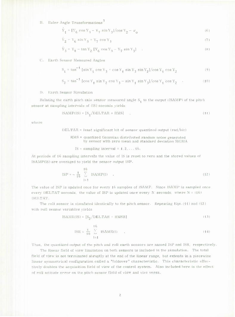
1. Momentum Wheel Speed Control
The control laws relating to the motor torque T,. and momentum Y_ to the wheel speed ref- erence input IRNP are given in this section. The actual relative wheel speed period Tp is simulated from the equation
Tp = 2TT/[Y5/XJ4 - Y6 + Y4Y8] . (15)
The control system determines the wheel speed period Tp by measuring the interval between
8 successive tachometer pulses. The value of Tp is quantized into LSB bits per second and is updated at the rate of once per period. The digital number used to represent Tp is given by
I I'M', where
IPNP = Tp(LSB) bits . (16)
The value of IPNP is compared once per period with the wheel speed command IRNP to determine the error in the loop.
[ERROR = (IPNP - IRNP) . (17)
The momentum wheel speed is binary controlled by either applying a constant reference voltage
or zero to the motor windings according to the control law:
If (ERROR 4 0) , TM = _T
2
If (ERROR >0) , TM = T1 (18)
This binary control loop is updated once per period. The reaction torque values T., T_ used in the simulation closely approximate the actual
nonlinear wheel control torques. This is accomplished by least-squares, fitting a first degree function to a set of experimentally determined torque values from the actual wheel.
T = A. + B.w , u> = momentum wheel speed = TT-T- 4
T. = A^ + B2w . (19)
The coefficients A., A~ are determined in a one g environment and to relate them to a zero g field requires a reduction in their value to compensate for the reduction in coulomb fric-
tion in space. The coefficients B., B2 will vary slightly with wheel temperature. This is taken into account when simulating various conditions in which the wheel operates.
BATE
IRNP (fi»ed constant) QN TERROR <Y'0 r _^;
* SAMPLING •'
IPNP
MOMENTUM WHEEL
n-r-;w|
MEASURE PERIOD AND
QUANTIZE TO 2 /xsec
TACHOMETER PULSES
_J Fig. 1. Mode PI: Constant wheel speed.
PITCH EARTH
SENSOR
r ,>^
v Y5ma«
'5 0
INTEGER MULTIPLICATION
BY XP1
PITCH
THRUSTERS
NTEGER
ADDITION
RATE LOOP
INTEGER ADDITION
INTEGER STORAGE
SATURATION FLOATING POINT MULTIPLICATION
BY XP2
TRUNCATION TO
AN INTEGER
IRNP. PRESET WITH ——
Fig. 2. Mode P2: Normal pitch control.
Since the momentum wheel always operates at a positive bias speed o> , the value of IRNP
will be limited within a fixed range of values for all operating modes.
2. Mode PI
In mode PI (constant wheel speed) shown in Fig. 1, the input to the wheel speed system
[RNP is fixed at a constant value. In this mode the wheel speed is held at its initial condition
value unless commanded to a different speed.
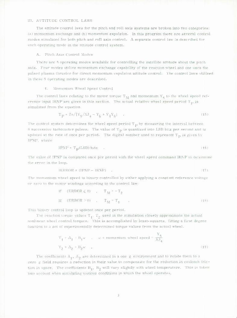
3. Mode P2
In mode P2 (normal pitch control) shown in Fig. 2, the input IRNP to the wheel speed system
is a function of the earth sensor output ISP. The control law for this mode uses momentum ex-
change to control the pitch pointing. In addition, a coarse momentum expulsion control law is
used to regulate wheel speed within fixed upper and lower bounds to prevent saturation. The
mode P2 control equations are given below.
IRNP = ISP(XP1)+ IQNP(XP2) . (20)
This relation is updated at intervals of N seconds when the value of ISP is updated. The con-
stants XP1, XP2 are parameters whose values are adjusted to yield optimum pitch performance
in mode P2.
V IQNP A 2, ISP
(N)NP
NP = integer N = 4 sec (21)
Relation (21) is updated at intervals of (N)(NP) seconds. The parameter NP is also adjusted to
optimize pointing performance in conjunction with XP1, XP2. The value of IQNP is limited to
the bounds
QNPMIN < IQNP < QNPMAX (22 )
to keep the wheel speed from saturating.
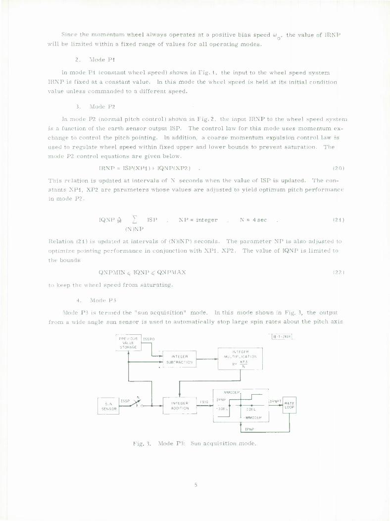
4. Mode P3
Mode P3 is termed the "sun acquisition" mode. In this mode shown in Fig. 3, the output
from a wide angle sun sensor is used to automatically stop large spin rates about the pitch axis
PREVIOUS ISSPO |l|-T- ?<04 1
STORAGE - INTEGER
MULTIPLICATION .
INTEGER
SUBTRACTION
1
+
ISIG N
MMODEP.
SUN
SENSOR
INTEGER ADDITION
IRNPT RATE
ISSP \jf
IDEL IDEL LOOP
L -MMO0EP
IPNP
Fig. 3. Mode P3: Sun acquisition mode.
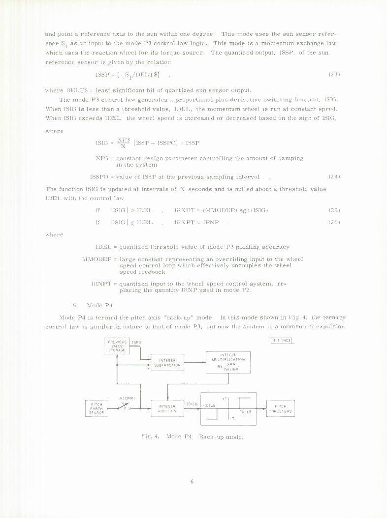
and point a reference axis to the sun within one degree. This mode uses the sun sensor refer-
ence S. as an input to the mode P3 control law logic. This mode is a momentum exchange law
which uses the reaction wheel for its torque source. The quantized output, ISSP, of the sun
reference sensor is given by the relation
ISSP = [-S /DELTS] (23)
where DELTS = least significant bit of quantized sun sensor output.
The mode P3 control law generates a proportional plus derivative switching function, ISIG.
When ISIG is less than a threshold value, IDEL, the momentum wheel is run at constant speed.
When ISIG exceeds IDEL, the wheel speed is increased or decreased based on the sign of 1SK;,
where
ISIG XP3
N [ISSP- ISSPO] + ISSP
XP3 = constant design parameter controlling the amount of damping in the system
ISSPO = value of ISSP at the previous sampling interval
The function ISIG is updated at intervals of N seconds and is nulled about a threshold value
IDEL with the control law:
(24)
where
If |ISIG|>IDEL , IRNPT = (MMODEP) sgn(ISIG)
If llSIGl^IDEL , IRNPT = IPNP
IDEL = quantized threshold value of mode P3 pointing accuracy
\1\U)DEP = large constant representing an overriding input to the wheel speed control loop which effectively uncouples the wheel speed feedback
IRNPT = quantized input to the wheel speed control system, re- placing the quantity IRNP used in mode P2.
(25)
(26)
5. Mode P4
Mode P4 is termed the pitch axis "back-up" mode. In this mode shown in Fig. 4. the ternary
control law is similar in nature to that of mode P3, but now the system is a momentum expulsion
PREVIOUS ISPC |ie-T-2«05|
STORAGE
INTEGER MULTIPLICATION
X P4 BY *
1NIIINP)
i
INTEGER SUBTRACTION
(NXINP)
ISIGB
• T I
PITCH EARTH
SENSOR •^Tt INTEGER
ADDITION
-IDELB 1 PITCH
THRUSTERS 1 IDELB
T
Fig. 4. Mode P4: Back-up mode.
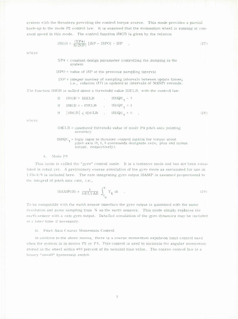
system with the thrusters providing the control torque source. This mode provides a partial
back-up to the mode P2 control law. It is assumed that the momentum wheel is running at con-
stant speed in this mode. The control function ISIGB is given by the relation
ISIGB = ^4p} [ISP- ISPO] + ISP , (27)
where
XP4 = constant design parameter controlling the damping in the system
ISPO = value of ISP at the previous sampling interval
INP = integer number of sampling intervals between update times; i.e., relation (27) is updated at intervals of N(INP) seconds.
The function ISIGB is nulled about a threshold value IDELB, with the control law:
If ISIGB > IDELB , ISEQU1 = 5
If ISIGB <-IDELB , ISEQU, = 1 1 If | ISIGB | < IDELB , ISEQU1 = 0 , (28)
where
IDELB = quantized threshold value of mode P4 pitch axis pointing accuracy
ISEQU. = logic input to thruster control matrix for torque about pitch axis (0, 1, 5 commands designate zero, plus and minus torque, respectively).
6. Mode P5
This mode is called the "gyro" control mode. It is a tentative mode and has not been simu- lated in detail yet. A preliminary coarse simulation of the gyro mode as envisioned for use in LES-8/9 is included here. The rate integrating gyro output ISAMP is assumed proportional to the integral of pitch axis rate, i.e.,
ISAMP(IS) = 5ELTÄK 1 Y6 dt • (29> lo
To be compatible with the earth sensor interface the gyro output is quantized with the same
resolution and same sampling time N as the earth sensors. This mode simply replaces the earth sensor with a rate gyro output. Detailed simulation of the gyro dynamics may be included at a later time if necessary.
B. Pitch Axis Coarse Momentum Control
In addition to the above modes, there is a coarse momentum expulsion limit control used when the system is in modes P2 or P3. This control is used to maintain the angular momentum
stored in the wheel within ±10 percent of its nominal bias value. The coarse control law is a binary "on-off" hysteresis switch
DYNAMIC COUPLING TORQUES
^ GIMBAL
DYNAMICS
Fig. 5. Mode Rl: Damping mode.
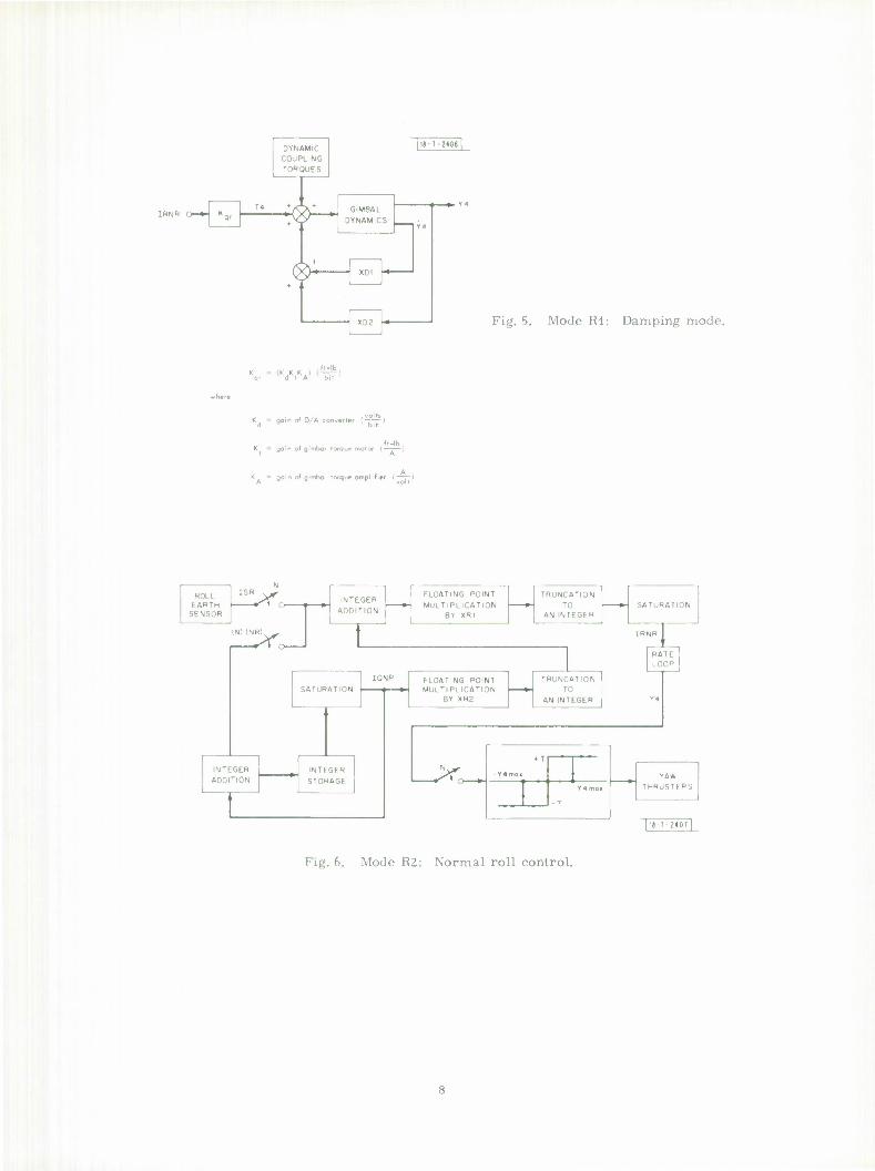
qr d I A bit
Kd = gain of D/A converter (^-)
K = gain of gimbal torque motor (—-—)
K - gain of gimbal torque amplifier (—p
ROLL EARTH
SENSOR O | »
INTEGER ADDITION
FLOATING POINT
MULTIPLICATION BY XRI
TRUNCATION
TO AN INTEGER
SATURATION
INTEGER ADDITION
INTEGER
STORAGE
FLOATING POINT MULTIPLICATION
BY XR2
TRUNCATION TO
AN INTEGER
SATURATION
HAT, I
OOP I
fAW THRUST! R'j
II-7-J40T
Fig. 6. Mode R2: Normal roll control.
If |Y5-Y50|<|Y50-Y5mln| , ISEQU, = 0
If Y5>Y5max ' ISEQU, = 5 until (Y,. - Y50U 0
If Y-<Ycmin , ISEQU, = 1 until (Y, - Ycn) > 0 , (30) b b 1 b bU
where
ISEQU. = thruster logic input for pitch torque command
Yc„ = nominal bias momentum value bu
5 min
5 max
C. Roll Axis Control Modes
There are 4 operating modes available for controlling the satellite attitude about the roll axis. Three modes utilize momentum exchange capability of the gimbal control system and one
mode uses the pulsed plasma thruster for direct momentum expulsion attitude control. The control laws utilized in these 4 modes are listed below.
1. Mode Rl
This mode, shown in Fig. 5, is termed the "damping mode" and consists primarily of a single analog rate loop used to generate heavy damping of gimbal angle rates. In Refs. 2, 4 it was shown that the existence of this loop caused active nutation damping at all times and iner- tially stabilized the large angular momentum vector stored in the momentum wheel. In this
mode the gimbal damping coefficient XD. and spring constant XD. are included in Eq. (1 ) as fixed control laws and the gimbal input IRNR = 0.
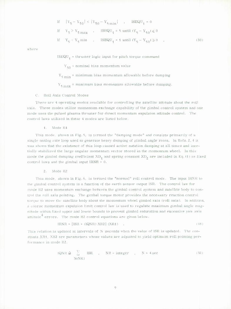
2. Mode R2
This mode, shown in Fig. 6, is termed the "normal" roll control mode. The input IRNR to
the gimbal control system is a function of the earth sensor output ISR. The control law for mode K2 uses momentum exchange between the gimbal control system and satellite body to con-
trol the roll axis pointing. The gimbal torque motor provides the necessary reaction control torque to move the satellite body about the momentum wheel gimbal axis (roll axis). In addition, a coarse momentum expulsion limit control law is used to regulate maximum gimbal angle mag- nitude within fixed upper and lower bounds to prevent gimbal saturation and excessive yaw axis
4 attitude errors. The mode R2 control equations are given below.
IRNR = [ISR + (IQNR) XR2] (XR1) . (31)
This relation is updated at intervals of N seconds when the value of ISR is updated. The con- stants XR1, XR2 are parameters whose values are adjusted to yield optimum roll pointing per- formance in mode 112.
IQNR £ ^ ISR , NR = integer , N = 4 sec (32) N(NR)
Relation (32) is updated at intervals of N(NR) seconds. The parameter NR is adjusted to opti- mize pointing performance in cooperation with XR1, XR2. The values of IQNR and IRNR are limited to the bounds
QNRMIN < IQNR < QNRMAX
| IRNR | ^ RMAX , (33)
to keep the gimbal control motor from saturating and thus provide no damping.
3. Mode R3
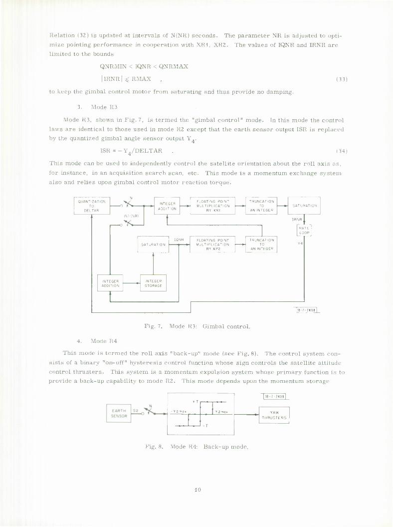
Mode R3, shown in Fig. 7, is termed the "gimbal control" mode. In this mode the control
laws are identical to those used in mode R2 except that the earth sensor output ISR is replaced by the quantized gimbal angle sensor output Y..
ISR = -Y4/DELTAR . (34)
This mode can be used to independently control the satellite orientation about the roll axis as,
for instance, in an acquisition search scan, etc. This mode is a momentum exchange system also and relies upon gimbal control motor reaction torque.
QUANTIZATION TO
DELTAR
N
INTEGER ADDITION
INTEGER
ADOITION
SATURATION
INTEGER STORAGE
FLOATING POINT MULTIPLICATION
BY XRI
FLOATING POINT MULTIPLICATION
BY XP2
TRUNCATION TO
AN INTEGER
TRUNCATION TO
AN INTEGER
SAT IRA1 ON
RATE LOOP
|l»-'-?40» |
Fig. 7. Mode R3: Gimbal control.
4. Mode R4
This mode is termed the roll axis "back-up" mode (see Fig. 8). The control system con-
sists of a binary "on-off" hysteresis control function whose sign controls the satellite attitude control thrusters. This system is a momentum expulsion system whose primary function is to provide a back-up capability to mode R2. This mode depends upon the momentum storage
r2 mi <
*T |IB-T-2409]
YZmo» YAW
THRUSTERS
-T
Fig. 8. Mode R4: Back-up mode.
id
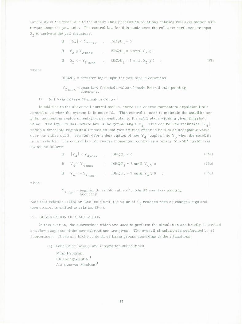
capability of the wheel due to the steady state precession equations relating roll axis motion with
torque about the yaw axis. The control law for this mode uses the roll axis earth sensor input
S- to activate the yaw thrusters.
It' ls, < Y, 1 2 ' 2 max ISEQU3 = 0
If S, > Y, 2-^2 max ISEQU3 = 3 until S2 ^ 0
il- S, < - Y, 2 2 max ISEQU 3 = 7 until S2 > 0 (35)
where
ISEQU, = thruster logic input for yaw torque command
Y» = quantized threshold value of mode R4 roll axis pointing accuracy.
D. Roll Axis Coarse Momentum Control
In addition to the above roll control modes, there is a coarse momentum expulsion limit
control used when the system is in mode R2. This control is used to maintain the satellite an-
gular momentum vector orientation perpendicular to the orbit plane within a given threshold
value. The input to this control law is the gimbal angle Y.. This control law maintains |Y.|
within a threshold region at all times so that yaw attitude error is held to an acceptable value
over the entire orbit. See Ref. 4 for a description of how Y. couples into Y, when the satellite
is in mode R2. The control law for coarse momentum control is a binary "on-off" hysteresis
switch as follows:
(36a)
(36b)
(36c) i *t iiiaA J *i
where
Y. = angular threshold value of mode R2 yaw axis pointing accuracy.
Note that relations (36b) or (36c) hold until the value of Y. reaches zero or changes sign and
then control is shifted to relation (36a).
I \ . I »ESCRIPTION OF SIMULATION
In this section, the subroutines which are used to perform the simulation are briefly described
and flow diagrams of the new subroutines are given. The overall simulation is performed by 1 ?
subroutines. These are broken into three basic groups according to their functions.
(a) Subroutine linkage and integration subroutines
Main Program
RK (Hunge-Kutta)1
AM (Adams-Moulton)1
[f Y < Y 1 4 ' 4 max ISEQU3 = 0
If Y. > Y. 4 4 max ISEQU3 = 3 until Y. < 0
If Y„ <-Y. 4 4 max ISEQU = 7 until Y4 $> 0
11
SET UP CONSTANTS COUNTERS
DEFAULT VALUES
|U-T-;4I0 1
CALCULATE PARAMETERS DEPENDENT ON INPUT
»/70 j » f STOP J
READ STARTING
VALUES
CALL TORK CALL OUTPUT
CALL RK CALL AM
CALCULATE REAL TIME
ON COMPUTER (volid-OS-only)
GENERATE PLOTS
RESET COUNTERS GO TO 10
Fig. 9. Flow diagram of main program.
1?.
(b) Satellite dynamics, kinematics, sensors and control law subroutines
DERIV
DIGIT
TORK
TORQUE UNLOAD
(c) Output format and plotting subroutines
GR 1 GR 2
OUTPUT IE V
PRINT V
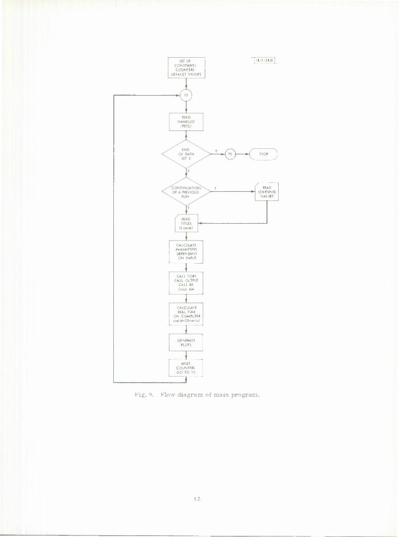
A. Main Program of the Simulation
The main routine sets up the initial conditions, reads each data set in turn, calls the simula- tion routines, and plots the results (see Fig. 9). There are several routines called in various
sections of the program which are in the Lincoln Library. They are DUMPV, TIMHR, REREAD, STOIDV, FRAMEV, PRINTV, PLTND.
The input is read in via NAMELIST/PETE/. All variables are computed in standard i neering units, degrees, degrees/second, rpm for the wheel speed. Those variables in the input
list whose units have to be altered for the simulations are stored as they are initialized and new variables hold the converted values. The variable names differ by 0 (zero) as the final character
of the variable name. Following the namelist, two title cards are read in. The program stores all 80 columns of the first card and the first 48 columns of the second card. Successive data sets
may be added for each simulation desired. The program may be terminated in either of two ways: (1 ) the absence of data to be read in terminates the program normally, (2) the namelist may be
read in with the logical variable FIN set to TRUE : FIN = T. The program was originally written to produce punched output with the intention of continuing
a particular simulation. Those write statements in subroutine AM on logical unit 7 are currently commented out. To read these cards back in, the user should initial all variables in the name- list as they originally were with the exception of the logical variable TOO : TOO = T. The punched
cards follow the namelist and precede the titles in the input stream. When this method of initial- ization is used, the array Y0 has units used by the program rather than engineering units. For
a successive data set, all of Y0 should be initialized. To perform the requested simulation the program makes an initial call to TORK to initialize
constants for the thrusting sequencing routine TORQUE and UNLOAD. These constants are used via the calls to the entry point THRUST in TORK. An initial call to OUTPUT stores the initial values of V to be plotted. The sequence of calls to RK and AM perform the simulation. Control returns to MAIN when T exceeds TBOUND. The stored arrays PY1, PY2, . . . PYn are plotted via calls to GR1. NFR controls the number of frames the data are to be plotted on; PT is the
array of times, PYi is the corresponding array of data. If PYi is constant throughout, no plot can be generated. IERR is returned nonzero. The calls to PRINTV label the last frame of each
set of frames per array plotted. The first and last frame for each simulation are the input parameters and titles.
1 J
SET UP COUNTERS
INITIAL VALUES
l8-7-24ll[
MOVE SENSOR OUTPUT TO BE RETURNED
CALCULATE IRNR
TO BE RETURNED FOR ROLL AXIS
( RETURN j
CALCULATE IRNP
TO BE RETURNED FOR PITCH AXIS
Thes« block» ore detailed in Figi. I Kot, 1Kb), 11(c) and 11(d).
RESET SAMPLING COUNTER
( RETURN J
Fig. 10. Main flow of subroutine digit.
14
After resetting the appropriate parameters and counters, program control returns to the
reader for another set of data for the next simulation. An empty reader terminates the program. The current size of the program requires that simulations totaling 2000 seconds or less be
run as Class C jobs under Lincoln's MVT, longer simulations are Class F.
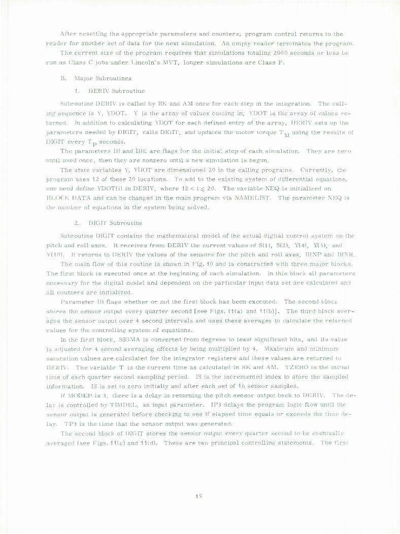
B. Major Subroutines
1. DERIV Subroutine
Subroutine DERIV is called by RK and AM once for each step in the integration. The call-
ing sequence is Y, YDOT. Y is the array of values coming in; YDOT is the array of values re- turned. In addition to calculating YDOT for each defined entry of the array, DERIV sets up the
parameters needed by DIGIT, calls DIGIT, and updates the motor torque T.. using the results of DIGIT every Tp seconds.
The parameters IB and IBE are flags for the initial step of each simulation. They are zero until used once, then they are nonzero until a new simulation is begun.
The state variables Y, YDOT are dimensioned 20 in the calling programs. Currently, the program uses 12 of these 20 locations. To add to the existing system of differential equations, one need define YDOT(i) in DERIV, where 12 < i^ 20. The variable NEQ is initialized on HI,OCR DATA and can be changed in the main program via NAMELIST. The parameter NEQ is
the number of equations in the system being solved.
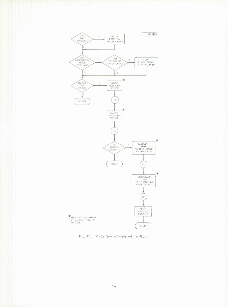
2. DIGIT Subroutine
Subroutine DIGIT contains the mathematical model of the actual digital control system on the
pitch and roll axes. It receives from DERIV the current values of S(l), S(2), Y(4), Y(5), and Y(10). It returns to DERIV the values of the sensors for the pitch and roll axes, IRNP and [RNR.
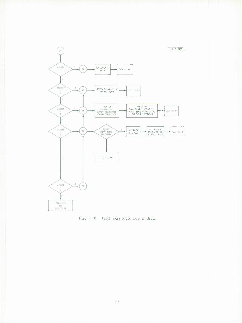
The main flow of this routine is shown in Fig. 10 and is constructed with three major blocks.
The first block is executed once at the beginning of each simulation. In this block all parameters necessary for the digital model and dependent on the particular input data set are calculated and
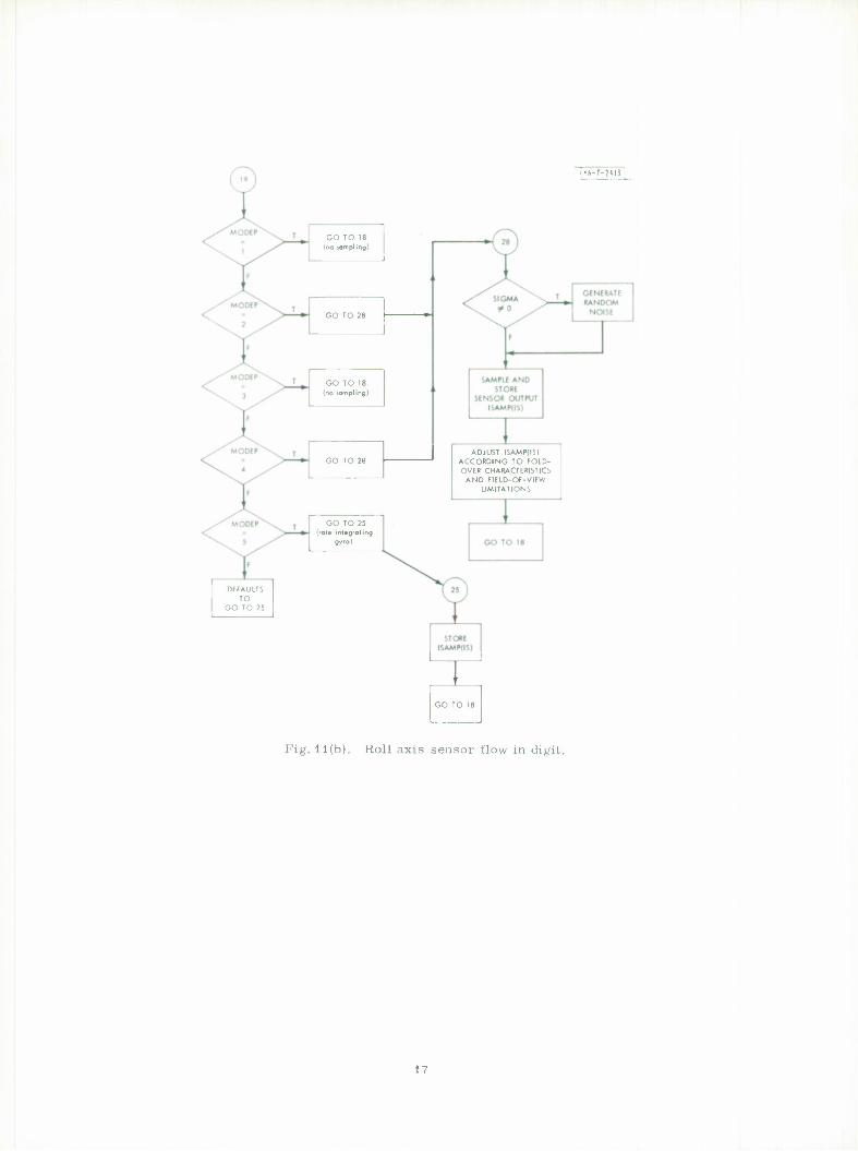
all counters are initialized. Parameter IB flags whether or not the first block has been executed. The second block
stores the sensor output every quarter second [see Figs. 11(a) and 11(b)], The third block aver-
ages the sensor output over 4 second intervals and uses these averages to calculate the returned values for the controlling system of equations.
In the first block, SIGMA is converted from degrees to least significant bits, and its value is adjusted for 4 second averaging effects by being multiplied by 4. Maximum and minimum saturation values are calculated for the integrator registers and these values are returned to DERIV. The variable T is the current time as calculated in RK and AM. TZERO is the initial time of each quarter second sampling period. IS is the incremented index to store the sampled information. IS is set to zero initially and after each set of 16 sensor samples.
If MODEP is 3, there is a delay in returning the pitch sensor output back to DERIV. The de- lay is controlled by TIMDEL, an input parameter. IP3 delays the program logic flow until the sensor output is generated before checking to see if elapsed time equals or exceeds the time de-
lay. TP3 is the time that the sensor output was generated.
The second block of DIGIT stores the sensor output every quarter second to be eventually averaged (see Figs. 11(c) and 11(d). These are two principal controlling statements. The first
15
GO TO 19 (no sampling)
U-T-WI?
GENERATE RANDOM
NOISE
SAMPLE AND STORE
SENSOR OUTPUT ISAMR(IS)
ADJUST ISAMR(IS) ACCORDING TO FOLD- OVER CHARACTERISTICS
AND FIELD-OF-VIEW LIMITATIONS
Fig. 11(a). Pitch axis sensor flow in digit.
If,
GO TO 18 (no sampling)
GO TO 18 (no sampling)
GO TO 25 (rate integrating
gyro)
ADJUST ISAMP(IS) ACCORDING TO FOLD- OVER CHARACTERISTICS
AND FIELD-Of-VIEW LIMITATIONS
Fig. 11(b). Roll axis sensor flow in digit.
17

|l»-7-?414l
IRNR = 0 GO TO 69
AVERAGE SAMPLED DATA
AND CALCULATE ISR
CONVERT Y(4) TO LEAST SIG BITS
TO GET GIMBAL RESPONSE ISR
DEFAULTS TO
GO TO 49
/EVERY\^ Nlh TIME \ , THROUGH^''^
UPDATE IQNR
I 1
SATURATE
AXIS
GO TO 69
Fig. 11(c). Roll axis logic flow in digit.
18
|1I-T-MI5|
CALCULATE IRNP
AVERAGE SAMPLES UPDATE IQNP
PLACE IN TEMPORARY LOCATION RESET TIME PARAMETERS
FOR DELAY OPTION
AVERAGE SAMPLES
USE RESULTS IN DUMPING LOGIC ISEQU
Fig. 11(d). Pitch axis logic flow in digit.
1 '
MODER 1
2
3
MOD EP 1
2
5
1
5
is a computer GO TO for the roll axis. The second is a computer GO TO for the pitch axis, i.e.,
GO TO (19, 29, 19), MODER.
When MODER = 1 or 3, the program logic flow goes to labeled statement 19. Likewise, when
MODER = 2, program control branches to labeled statement 29.
Value Meaning
DAMPING MODE
POINTING MODE
GIMBAL CONTROL MODE
CONSTANT SPEED
POINTING MODE
ACQUISITION MODE
PITCH BACK-UP MODE
HAIL INTEGRATING GVRO MODE
To increase the number of modes for either roll or pitch axis, another labeled control sec-
tion must be added and the label put in the list for the appropriate computed GO TO statement.
tn DERIV, regardless of which roll axis is used, control passes eventually to labeled statement
19, the computed GO TO for the pitch axis. The various pitch modes finally pass control to
labeled statement 18 where TZERO is set, and IS is checked to see if 16 samples have been
stored. If less than 16 samples are in storage, control returns to DERIV. Otherwise, control
passes to the third block in DIGIT.
For the roll axis, no sampling takes place in modes 1 and 3. For mode 2, the values oi
V(2), (S(2) in DERIV) are stored. The decimal fraction of Y(2) is truncated; the integrals re-
maining are then converted from radians to least significant bits. For a nonzero SIGMA, a
random number from a Gaussian distribution is added to Y(2). The storage array is ISAMR.
According to the value of Y(l), (S(l) in DERIV), limits of the field of view for the sensor are de-
termined. If Y(l) is outside the field of view, FOV, a zero is stored. If the absolute value of
ISAMR lies between 1024 and 2047, the difference between 2048 and ISAMR is stored with the
signs of the original value. This process is referred to as the "fold over" sensor characteristic.
When the roll axis sensor output is stored, the program then repeats the procedure for the pitch
axis sensor.
For the pitch axis, no sampling takes place for modes 1 and 3. For mode 5, the variable
Y(10) (the rate gyro output) is converted from radians to least significant bits and stored in
ISAMP. For pitch modes 2 and 4 the current value of Y(l) plus any random noise is stored In
ISAMP. The random noise is selected from a Gaussian distribution with standard deviation,
SIGMA. For SIGMA equal to zero no noise is added. The program compares SIGMA ± EPS
(where EPS is a small number) with zero, since testing on equality with real numbers is not al-
ways reliable. If Y(2) indicates that the sensor is out of the field of view, ISAMP is set to zero.
The fold over sensor characteristic is identical for both the pitch and roll axis sensors.
After the pitch axis information is stored, TZERO is reset. IS is compared to see if 16 sam-
ples have been taken. The 16 samples parallel the actual 16 samples taken every 1/4 second for
4 seconds. A counter rather than absolute time is used because of the variety of time increments
possible to be used by AM. Four seconds could mean 15 or 17 samples taken. If IS is less than
16, program control returns to DIGIT.
20

When IS equals 16, program control passes to the third block of DIGIT. The integer N is a
continuous counter of the number of times sensor averaging has taken place:. Thus, certain
calculations can be done every i change in N by a comparison of N mod i with zero.
In the third block of DIGIT, the two principal control statements are computed GO TO's for
roll and pitch axis. Any additional modes added in the second block must also be added to these GO TO's even though the averaging logic is the same as some previous mode. Whatever roll
axis mode is used, control eventually passes to labeled statement 69. Statement 69 is the com-
puted GO TO for the pitch axis. Each pitch mode eventually returns to labeled statement 68.
Here the counter IS is reset to zero and control returns to DERIV.
For the roll axis, mode 1 returns a zero in the output IRNR. For mode 2, the 16 stored
sensor values are averaged as ISR. For mode 3, Y(4) is converted from radians to degrees and
then quantized and stored as ISR. The variables ISR and IQNR are used to calculate IRNR. IQNR is updated by ISR every NR time and is limited by QNRMAX and QNRMIN. The absolute value
of IRNR is limited by RMAX and is returned to DIGIT. After this operation, control passes to the computed GO TO for the pitch axis.
For the pitch axis, mode 1 returns the initial wheel speed with appropriate unit manipulations via IINT as IRNP. For mode 2, the 16 samples in ISAMP are averaged and the result stored as ISP. INDEX is a counter for storage of time and sensor output to be plotted. IRNP is calculated
using ISP and IQNP where IQNP is updated by ISP every NP time through the loop. IQNP is
bounded by QNPMAX and QNPMIN. For mode 5, the output of sensor one, V(l) is bounded by ± and converted from radians to least significant bits and stored as ISSP. For the time delay
option TP3 is set to T, IP3 is set to 1. For mode 4, control law calculations take place every INP time and this affects the values
of ISEQU. ISEQU controls the sequence of the firing of the thrusters. In this mode IRNP is returned as in mode 1.
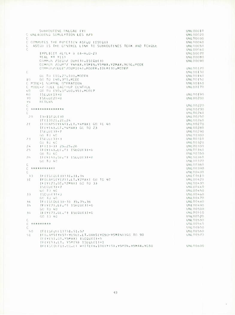
3. TORK, TORQUE, and UNLOAD Subroutines
The three subroutines TORK, TORQUE, and UNLOAD provide DERIV with the appropriate
torques, LI, L2, L3, which simulate the firing of the thrusters. Subroutine TORK is called
once per simulation from the main program to establish certain tables dependent on the physical location of the thrusters on the satellite body. Subroutine TORQUE is called once per integra- tion step by both AM and RK. UNLOAD is called each time TORQUE is entered. If it is time to fire a thruster, TORQUE calls TORK via ENTRY THRUST. At this time torques LI, 1.2, L3
are updated for DERIV. The thruster torques are passed through COMMON/CONTROL/ and they have different
names in each routine.
Subroutine Variable Name
TORK T(l) T(2) T(3)
TORQUE L(l) L(2) L(3)
DERIV LI L2 L3
In each routine they are REAL*8 variables.
Subroutine TORK accepts as input the distance in inches of the thrusters from the origin of
the satellite reference frame. TORK establishes a torque look-up table, TABLE, first by filling
in the signs (+ or —) of the torque components for each thruster in a 12 x 3 array. It then computes the magnitudes of the torques and replaces each entry with the torque components
l\
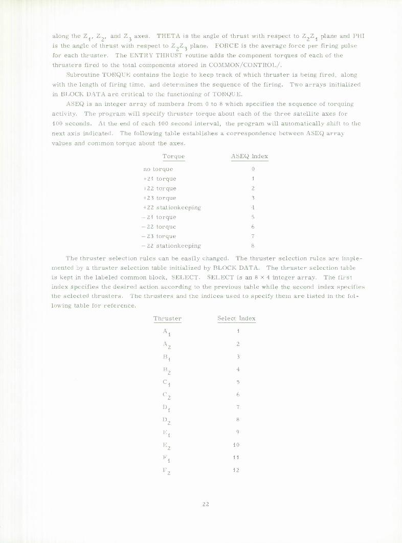
along the Z., Z_, and Z, axes. THETA is the angle of thrust with respect to Z?Z. plane and Nil
is the angle of thrust with respect to Z_Z, plane. FORCE is the average force per firing pulse
for each thruster. The ENTRY THRUST routine adds the component torques of each of the
thrusters fired to the total components stored in COMMON/CONTROL/.
Subroutine TORQUE contains the logic to keep track of which thruster is being fired, along
with the length of firing time, and determines the sequence of the firing. Two arrays initialized
in BLOCK DATA are critical to the functioning of TORQUE.
ASEQ is an integer array of numbers from 0 to 8 which specifies the sequence of torquing
activity. The program will specify thruster torque about each of the three satellite axes for
100 seconds. At the end of each 100 second interval, the program will automatically shift to the
next axis indicated. The following table establishes a correspondence between ASEQ array
values and common torque about the axes.
Torque ASEQ Index
no torque 0
+21 torque 1
+ 22 torque 2 +23 torque ? + 22 stationkeeping 4
— 21 torque 5 -22 torque 6 — 23 torque 7
— 22 stationkeeping 8
The thruster selection rules can be easily changed. The thruster selection rules are imple- mented by a thruster selection table initialized by BLOCK DATA. The thruster selection table is kept in the labeled common block, SELECT. SELECT is an 8 x 4 integer array. The first index specifies the desired action according to the previous table while the second index specifies the selected thrusters. The thrusters and the indices used to specify them are listed in the fol-
lowing table for reference.
Thruster Select Index
Al 1
A2 2
l!l 3
l!' 4
Cd 5
C2 6
"l 7
D2 8
El 9
E2 10
"', 1 1
'•'z 12
21
This table is used for the selection of up to four thrusters to provide torque about each axis.
ASEQl is passed in common/SEQU/ and SELECT in common/TABLES/. ATIME and ALI
are the current length of time of firing and maximum allowable time of firing about the current
axis. TTIME and TLIMIT are the current length of time of firing and maximum allowable time of firing with the current thruster. APOINT specifies the current axis. TCUR specifies the cur-
rent thruster. The call to THRUST is made with the appropriate value of IFIRE taken from an appropriate place in SELECT. With the three forces updated, control returns to DERIV.
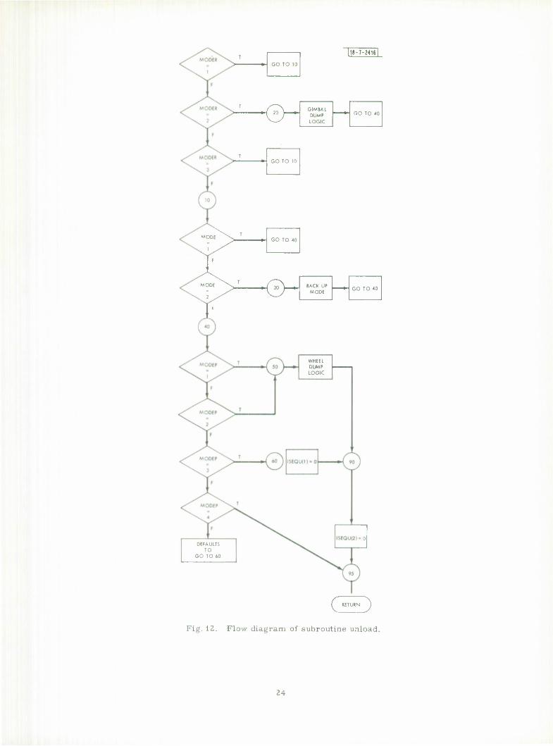
\i the beginning of TORQUE is a call to subroutine UNLOAD (see Fig. 12). The values of
ASEQU are updated depending on the values of MODER and MODEP (ASEQU is called ISEQU in
1 NLOAD). First the roll axis modes are examined, then the pitch axis modes. If the roll axis mode is 1 or 3, there is a choice of a back-up mode, MODE = 2. If there is no back-up on
modes, UNLOAD does nothing. If MODE = 2, ISEQU(3) is changed to 0 or 3 or 7 depending
on the previous value of ISEQU(3), the current value of V(4) and the maximum limit on Y(4)( YMA.X).
In the back-up mode for the roll axis, ISEQU(3) becomes 0, 3, or 7 depending on the previous value of ISEQU(3), the current value of Y(2) and the limiting Y2MAX. This is referred to as the gimbal dump logic.
For the pitch axis in modes 1 and 2 the value of ISEQU(l) is changed to 0, 1, or 5 depending
on the previous value of ISEQU(l), the current value of Y(5), the upper and lower limits, Y5MAX and "> 5MIN, and the initial wheel speed Y050. This is referred to as the wheel dump logic.
(.'. Output Format and Plotting Subroutines
The printed and optional punched output is produced in subroutine AM. The plotted output is stored by OUTPUT and plotted by GR1 and GR2. OUTPUT is called periodically by AM, every
2 seconds. To alter the frequency, MPT should be changed in BLOCKDATA and AM. The fre- quency of points plotted is related to the initial step size HO.
. 256* no frequency = MpT
Printed output is produced every TBOUND-TO/10 seconds, to yield 10 sets total per simulation. Punched output is produced at the end of each simulation. The punched output is in Z format as
it is intended for machine use only. The punched output does not include the current sensor in- formation from DIGIT.
Subroutine GR1 is called from the main program once for each variable to be plotted. The tall inn sequence is NFR, X, Y. NFR is the number of frames to spread the data over; X is the array of horizontal values, Y is the array of vertical values. GR1 calls GR2 passing necessary parameters via COMMON/GR/. GR2 calls the SC4020 routines necessary to produce a grid, points, and lines connecting the points. If all the Y values are constant, no grid can be drawn, as the scale on each grid is dependent on the range of the Y values. In case no grid can be
drawn, a flag, IERR, is returned non-negative. No further processing is performed in GR2 and lag is returned to the main program via common/SKIP/ so that the printing of the titles is
skipped also. If it is desired to add the plotting of another variable, the variable should be stored in an
array in subroutine OUTPUT. The array should be dimensioned 5001, should be REAL I,
and should be in common /OTPT/ in both OUTPUT and in MAIN. In MAIN two additional cards
are needed, one call to GR1 and one conditional call to PRINTV to produce a title on the plot.
Deleting a frame of output is similar.
2 i
T
GO TO 10
&~ GIMBAl DUMP LOGIC
GO TO 40 '
T GO TO 10
DEFAULTS TO
GO TO 60
MODE . T
GO TO 40
1 ,/
T
TF
MODE ^Jr~ BACK UP MODE
GO TO 40
7 s/
I 1
WHEEL DUMP LOGIC
( RETURN J
Fig. 12. Flow diagram of subroutine unload.
24
V. USE OF THE PROGRAM
The required program input variables along with typical values used and the output data
format are described in this section. For each computer run input data are printed out at the
beginning of the run to identify the parameter values used. The input variables are listed below
in the same order as required in the program.
A. Input Variables
HO = initial computation step size (seconds)
TBOUND = final computation time (seconds)
TO = initial computation time (seconds)
YO = initial conditions of variables Yl through Y12, respectively, at t = TO
NFR integer number of frames of plotted output per simulation
FIN = F or T, logical false or true which stops program
TOO = F or T, logical false or true which is used to signify continua- tion of a run
GLB = greatest lower bound limit on integration error over one step (to-7)
LUB = least upper bound limit on integration error for one step (10"^)
XJ = principal inertias of satellite and reaction wheel rotor (XJ1, XJ2, XJ3, XJ4)
Z2 thruster location distance from satellite center of gravity on coordinate Z2 (inches), one dimension
Zl - thruster location distances from satellite center of gravity on coordinate Zl (inches), two dimensions
ASEQU - three integers representing the initial values of thruster firing command about pitch, roll, yaw axes, respectively
XP1 pitch axis proportional gain parameter (integer)
XP2 = pitch axis integral gain parameter
XI) 1 = nutation damping coefficient parameter
XD2 = gimbal flexible spring constant
XD3 not being used (spare parameter)
XI! 1 roll axis proportional gain parameter
XR2 = roll axis integral gain parameter
MODI: (1 or 2) roll axis back-up enable switch indicating normal or back-up control mode operation
SIGMA RMS value of random noise output of earth sensor (deg)
NR = roll axis integral gain sampling ratio (integer)
U< '1)1:1; - integer representing desired roll axis operating mode (1-4)
25
MODEP = integer representing desired pitch axis operating mode (1-5)
MMODEP = integer number input to wheel speed control in pitch acquisition mode
IDEL = integer number representing deadband in pitch acquisition mode (bits)
TIMDEL = time delay in updating pitch acquisition mode logic after each sensor sample (seconds)
NP = pitch axis integral gain sampling ratio (integer)
M2 = gimbal misalignment angle about the Z? axis (radians)
M3 = gimbal misalignment angle about the Z axis (radians)
XP3 = pitch axis derived rate gain parameter in acquisition mode (integer)
LSB = wheel speed period resolution (bits/second)
TD1 = external torque about pitch axis (ft-lbs)
TD3 = external torque about yaw axis (ft-lbs)
Y4MAX0 = maximum gimbal angle allowable in roll axis normal mode before momentum dumping (degrees)
Y5MIN0 = minimum wheel speed allowable before momentum dumping starts (rpm)
Y5MAX0 = maximum wheel speed allowable before momentum dumping starts (rpm)
V2MAX0 = deadband in roll axis back-up mode (degrees)
Y5N0 = nominal bias wheel speed (rpm)
XP4 = pitch axis derived rate gain parameter in back-up mode (integer)
EDELB = integer number representing deadband in pitch back-up mode (bits)
INP = sampling ratio of pitch back-up logic to sensor sampling (integer)
Typical values for the above defined variables for simulation of the LES-8/9 current configura-
tion are given below:
HO = 0.25sec, TBOUND = 300 —1200 sec, TO = 0.0
Y0 = (initial conditions for all state variables), Y,0 = initial pitch axis error (degrees)
Y7n = initial roll axis error (degrees), Y,n = initial yaw axis error (degrees)
Y.n = initial gimbal angle (degrees), Y . = initial wheel speed (rpm)
Y, - initial pitch axis body rate (deg/sec), Y = initial roll axis body rate (deg/sec)
Y . = initial yaw axis body rate (deg/sec), Y_ = not used = 0
Y.Q0 = initial value of integral of Y., Y 1Q = initial ITAE value for pitch error
26

120 initial ITAE value for roll error, NFR = 1, FIN = F,
TOO = T, GLB = 10"7, LUB = 10~5,
\M (values of inertias): XJ 1 = 120 slug-ft2, XJ2 = 130 slug-ft2
XJ3 = 28 slug-ft2, XJ4 = 0.065 slug-ft2, Z2 = 20 inches,
Zl = 14.75, 16.25 inches, ASEQU = 0, 0, 0
XP1 = 2, XP2 = 0.125, XD1 = 6.0ft-lbs-sec/rad, XD2 = 0.3 ft-lbs/rad
XD3 = 0, XR1 = 0.25, XR2 = 0.5 MODE = 1, SIGMA = 0.03 degrees
NR = 2, MODER = 2, MODEP = 2, MMODEP = 200,000, IDEL = 24,
TIMDEL = 0, NP = 3, M2 = 0, M3 = 0, XP3 = 6,
LSB = 500,000, TD1 = 0, TD3 = 0, Y4MAX0 = 0.1 degrees,
V 5MIN0 = 1000 rpm, V5MAX0 = 1200 rpm, Y2MAX0 = 0.1 deg,
Y5N0 = 1100 rpm, XP4 = 200, IDELB = 20, INP = 5.
B. Output Data
Output data from the program described here is in the form of plots. The subroutines used to generate the output plots are described in Sec. IV-C. Typical transient response plots of the variables Y Y,, Y_, versus times are illustrated in Figs. 13, 14, 15, respectively. The input
lor these runs are listed in Sec. V-A. The plot coordinates are scaled in common units for of analysis; deg, deg/sec, bits, rpm, seconds.
In addition to the plots, each computer run contains a torque table printed out at the top of
nput variable listing. This table is the output from subroutine TORK and consists of a
s «-
TIME <MC) -•- 200
TIME (»«> —
. 1 3. Computer plot of pitch transient response.
Fig. 14. Computer plot of roll transient response.
.27
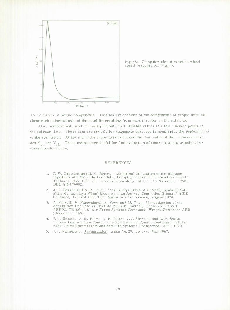
Fig. 15. Computer plot of reaction wheel speed response for Fig. 1 3.
200 300
TIME (MCI -*•
3x12 matrix of torque components. This matrix consists of the components of torque impulse
about each principal axis of the satellite resulting from each thruster on the satellite. Also, included with each run is a printout of all variable values at a few discrete points in
the solution time. These data are strictly for diagnostic purposes in monitoring the performance
of the simulation. At the end of the output data is printed the final value of the performance in-
dex Y. . and Y.,. These indexes are useful for fine evaluation of control system transient re-
sponse performance.
REFERENCES
1. R. W. Brockett and N. M. Brody, "Numerical Simulation of the Attitude Equations of a Satellite Containing Damping Rotors and a Reaction Wheel," Technical Note 1968-24, Lincoln Laboratory, M. I. T. (15 November 1968), DDC AD-679992.
2. J. I". Beusch and N. P. Smith, "Stable Equilibria of a Freely Spinning Sat- ellite Containing a Wheel Mounted in an Active, Controlled Gimbal," AIEE Guidance, Control and Flight Mechanics Conference, August 1970.
3. A. Sabroff, R. Farrenhopf, A. Frew and M. Gran, "Investigation of the Acquisition Problem in Satellite Attitude Control," Technical Report AFFDL-TR-65-115, Air Force Systems Command, Wright-Patterson AFB (December 1965).
4. J. U. Beusch, F. W. Floyd, C. H. Much, V. J. Sferrino and N. P. Smith, "Three Axis Attitude Control of a Synchronous Communications Satellite," AIEE Third Communications Satellite Systems Conference, April 1970.
5. J. J. Fitzgerald, Accumulator, Issue No. 29, pp. 3-4, May 1967.
28
APPENDIX
(. C C SMORT TERM 5IMUIATION FDR LES-7 TEM00040
fMPLICIT KE'L*Ö (A-H.O-Z) TE^OOO^O
DIMLNSION T'TL.L(16),Y(20),Y0(20),P(4),C(4),m20,5),XJ{4),LA6EU49TFM00(.M> 2), L 1(2) TEM00070 LflGlCAL FI.J, TOO, TERM TFV00080 I4TEGER ASL~U(3), APulNT TFM00090 KCAL*P M2.M-* ^TAL*'. l>Yl(r'001),PY2(bO(jl),f,Y3(bOOl),PYM')001),PYb<'J001),PT(t><)01),TEv"
2 TIME1, riME2, ELTIME, ITIME TEMOOllO -UAL*4 PY7(t>001) Kl AL*'. XT , YT
REAL** LUU, K TFM00120 OCOMMON /CljEr/P.Cf TUlJUNDf WR.MPT.NCT, NSTEP, Nf 0 TFM0O13O 1 /OTPT/PT.PY1,PY2,PY3,PY<t,PYb TEM00140 2 /PARAM/XJ,XJ23,XJ31,XJ21,Tl,T2,ÜMbr,A0,XPl,XP2,XDl,XD2,XD3, TEMOOlbO 1 XRI.XK2 TEM00 160 i /AWDM/HSCO TEM00170 4 /Sfcg'V H, ATIKL, TTIME, ASElwU, APOINT TEMC01RO b /GR/ PUMIDf NPL TEM00190 COMMON /FKt'V YC'JC!, INCLX
IN /PLÜT/ XT(bOOO),YT(SOOC) COMMLiN /AL l"N/ M2,M J
'••' )'. /SKI"/ IcRR C( MMuN/PI rCi/XPA,IDELh,INP COM MOM /ELL' N/ r IKOEL i T IM, SIGMA , Ib,NP,MODER,NR, IRNP.IRNR.MOUEP,
2I')LL »MMCOEP, I PNP.XP i.LSb COMMON /UM-1/ PY? COMMON /OISTUH/ TP 1 ,TH3 COMMON /IHK-1r'/Y4MAX,Y')MlN,YbMAX,Y2MAX,Y5N,MOIJE Rl AL *4 SP(b^0l,2) COMMUN /RCTTtK/ S(2),SP DATA TOO, rr-!/TtF/,Y()/20*O.DO/,GLB,LtB/l. 0-7,1.0-5/ TE MO 0 200 ÜA T ft PI /J.141592653589793/, /l, l? /14.7b, 16.20, 20.0/ TEM00210 JAKLLlSt /PFTE/hO, THUbNU , TO, YO, NFR , F I N , TCO, GLH , LLL , XJ, TFM00220
2 /2,Z1,ASEQU,XP1,XP2,XP1,XD2,XD3,XR1,XR2,MÜDE, 3 SIGMA,NR,MÜDER,MCDEP,MMCDEP.IDEL,TIMCEL,NP,M2,M3, ^ XP3,LSb,TDl,Tn3,Y4MAX0,Ye>MIN(J,Y5KAX0,Y2MAXG,Yc>N0 4 ,XP4, ICELE, INP
C TFM00240 C TEMO02S0
CALL SiniüVf•ATTITUOt CONTROL SYSTLM PLTh SrlTH C-371 XbClb', 146,0) LALL ÜUMPV '264) CALL REREAD (8,300) TEM00280
C TFMO029O r u i = i. T n 3=o. o H0=.l25 ro=u.n Y4MAX0*.1 Y5MI MC=10C0. Y5MAXO*1200. Y ? M A X 0 = . I Y5'M(J=1100. \|FR = 1 NF(«=12 P( 1 )=-. )7'^J'1 TIM003UO
29

P( 21=37.n0/?4.DO P< 3) =-59.00/24.DO P(4)*55.00/74.DO C( 1 ) = 1. CO/?'.. 00 C(2)*-5.DO/?4.UO c( 3) = l i.no/^.uo CIM = . 17500 OMLGAO = (2.0D+00)*PI/(24, 00+00*3.6T+03)
C P-FG INNING OF IN^UT LOOP C FOK PETt SMITH ""HE UNITS OF THfc INPUT WERE CHANGFD TO DEGRECS
10 RFAC (5,PtT,r,tNÜ = 70) C AND FOR THE WHEH. SPF.FD TG KPM
INIU.X = 0 KAD=57.2957° DU 750 ISP=1,4
750 Y( ISP)=YO( l^P) /RAO Y( 5 I = Y0< 5)*.0Ü68055 Y05G=Y(S) D(l 7J1 IPS-' ,NEQ
751 Y(IPS)=YO(["bl/KAO Y*MAX*Y4MAX"/RAn Y2MAX=Y?MAXr/KAU YSMI M = Y5M.lNn*.0068055 Y5MAX = Y5MAX"'*.U06R055 Y5N=Y5N0*.0^68055 IF (TIN) GO TU 70 IF (TOO) GU TO 30 KFAO (4,20) TOtYO
20 FORMAT (Zl<>) CO 60 I»l, NEC
60 Y( 1 )=Y0( I ) GO TU 4C
jo TO=o.no 40 READ (4,40) TITLE 00 FORMAT (1CA°)
INITIAL ANGULAR MUMtNTUM X = Y( 5)*( Y(M*Y(4 1 + Y< R) ) HSQO«(XJ< 1)*Y(6)+Y(5)*DC0S(Y(4)))**2+XJ(2)*YI
1 Y( 5)*DMN( Y(4) ) )**? XJ23=XJ(?)-*J(3) XJ31=XJ( 3)-vJ( 1 ) XJ21=XJ(2)-vj( 1 )
H*HO r = r r i T I M= T IPRN=O in=o CALL T0<K(Z1, t/.\ WR = ( THOIIN0-T0)/LO.D0 WRITE (6,P£TG) WRIT,: (6,61) TITLF
61 FORMAT I•1',16AH)
REGIN SMULATIO" TERM« .FAL St.. S(I ) =0.0
7)**2+(XJ( 3)»Y(HI-
TEM00310 TEM00320 TFM00330 TEM00 340 TEM00350 TEM00360 TEM00370 rEM00380 TEMO0390 TEM00400
TEMO TEMO TEMO TEMO TEMO TEMO TEMO TFMO TEMO TEMO TEMO TFMO
0430 0 4 40 0440 0460 0( 30 0640 0470 0480 0 4 9 0 0000 0010 0520
TFM005/0 TFM0058O TfM00090 TEM00600 TEM00610 TFM00620
TEM00640 TFM00660 TEM00670 TEM00680 TFMQ0690 TEM00700 TFM00710 TEM00 720
30
64
SI2>=0.0 CALL OUTPUT!r,Y,TERM)
CALL I 1"HR( TIMC-1 ) CALL »K(H,T,Y,lY,TERM) CALL AMIH,T,YtFY,GLB,LUb,TEKM)
CALL TI"HRITIME2) ELT IMF = I [ME2 - TIME1 [TIKE * (LLTI^L/NSTIP)*3600.0 r L T MI = f-LT lt>t*b0.0
WIlKb.WI I T I ME, ELTIME 62 ''All' tLAPSEO TIMf FUR ONE I
2ULATICN TIM*" = «, F 7. t>, • MINUTES» WRITt(6,64)v( 11 )
WRITt(6,65) Y(12) FORMAT!//» "ERFORMANCE INDICATEOR
60 FORMAT!//« PERFORM AMCf INDICATEOR
C PLOT IM ksK 1
FORM 1 F 6 . 1 READ i riRf
f, j
' 7
tGKAL CURVES. I • ( •I.63M YOi I ) , 1 = 1, 11 ) ,HO,TO,TBCUND,XJ ATI•Y0*',11(F9.4,' ,•),• ',•hO=,,F6. 1,'. ,» SCC. , J=»,3(G10.3 ,», •),•JA*«.G10.3) (8,t,7) LABEL
AT ( if9A<• )
TEVO0730 TEM00740 TFM00750 TEM0076n TE^rtn77n TEM007P0 TEM00790 TFM00800 TEWOORin
Jl•^^^ ION • • ,F7 )
.5,' SECONDS SIMTFMOOP20 TFM00830
FCR PITCH AXISO ,G10.3) FOR ROLL AXISO ,010.3)
TEM00B40 TFM00850
,F6. 1^ ro
70
CALL FRAMLV(O) CALL °<INTV(128,TITLt,0,975) CALL PRINTVI 124,LABEL,0,895) CALL PRlNTVt-14,•INITIAL VALUES',50C,1010) CALL PRINTVI72,LABEL! 321,0,86*>) CALL GRMNF^.PT.PYl) IF (lERR.tO.OICALL PK I N T V ( - I 1 , • CPSLM VS T»,0,1007) CALL GRl <\T',,PT,PY2) If I I I ?>.LU.0)CALL PR1NTVI-1 1 , »CPSLN2 VS T«,0,1007) CALL OR 1 (NF%PT,PY 3) IT IIERR.LQ.OICALL PR I NT V( -11 , • F.PSLN3 VS T», 0,1007) CALL .< I I \f~ ' ,PT,PY4 ) IF ( ITR R.L J.01CALL PKlMVI-11,' THETA VS T»,0,1007) CALL GRl(NFn,PT,PY5) II I IERR.tQ.OICALL PR I NT VI -14, • HHEEL-MOM VS T»,0,1007) CALL GR I (NFr,,PT,PY7) II ( II R*.FLi.")CALL PR I NTV (-4, 'Y(h) " , C, 1007) CALL GRllNFn,PT,SPU, 1) I IF! lEKR-ECMCALL PRINTVI-13, »SENSOR 1 VS T»,0,1007) CALL GR1INF0,PT,SPI 1,2)1 IFIIER.EC.OI CALL PR 1 NT V(- 1 3,•StNSOR 2 VS T»,0,1007) NPL= INOEX [F(MUDEP.ECJ.2)CALL GRKNFR.XT ,YT) CALL FRA^tV'O) CALL PRINTVI 128, TlTLt ,0,975) CALL PRINTVI 12 4, LA [S L: L , 0,895) CALL PRINTVI72,LABELI32),0,865)
NPL = ) TT1ME = 1.0'' + 03 AT1MC = l.0°+03 APOINT = 0 NSTI P * 0 Uli T.j IG C 0 M T I •
TFMr>0900 TEM00910 TEM00920 TFM00930 TFM00940
TEM00960
TEK00990
TEK01C20
TFMO 1( 50
TFM01080
TEM01 100 TEM01 110
TEM01130 TEMO 1 1*0 TEM0U50 TFMDl 160 TEM01170 TFM01 180 TFM0 1 1 »0 TF^ni2on
CALL PLTNC STUP END
****»**•**********#*•***
TE»">1210 TEKO1220 TEM01230
31

SUbKUUTINt pERl V( Y, YUOT ) 12 3 A 5 6 7 8 9 10 11
Y=EPS1,EPS2,EPS:STHETA,WHEEL-MOM,OMl,OM2,OM3,Xl,X2,X 1
IMPLICIT Kt"L*R (A-H,(J-Z) rRQUES
RLAL*H M2tl*n REAL»H LI, 12, L3 (JI ML MSION Y( 1 ) , YUOT! 1) ,XJK) COMMON /ALI'N/ M2,M3 COMMON /LLLffM/ TIMOEL,TIM,SIGKA,IÜ,NP,MODER,NR,IRNP,lRNR,MOi;( P,
2IDEL,MMGDEP,1PNP,XP3,LSH COMMON /PAK'M/XJ,XJ23,XJ31,XJ21,T1,T2,OMEGA0,XP1,XP2,XD1,XD2,XD3,
2 XK1.XK2 2 /COMTRL/ LI, L2, L 5 COMMON /Li I STUB/ T01, TD3 RlAL*4 SP(5n01,2)
c c
COMMON /BCTTtR/ S(2) ,SP
OFFINTK.'M 1 JF CUK'TRUL VARIABLES K. NAME OESC'-1 IPT ION SYSTEM LNI TS c XP1 P''UP PI TCH SEC. Ü -1 c X.P2 P'TEoKAL PITCH SEC. D-2 c XDl DrKl VAtlVE DAMPER NONE : X;J2 PROP DAMPER SEC. D -1 c XR 1 P"OP ROLL SEC D -1 c XR2 INTEGRAL ROLL SEC D -2
15
T l = .0 64 7-.<./.6D-3*Y( bl/XJU] T?«-.0010?*.6627D-4*Y(5)/XJ(4) CY1=UCUS(Y(1)) SYl*OSIN(Y( 1 I) CY2=UC0S(Y<?)) SY2*DS!NI Y( '1 ) CY"i»DCOS(Y( "•) ) SY3*DSINI Y< "») ) TY2^SY2/CY2 S(1)=0ATAN2(SY1*CY3*CY1*SY3*SY2, CYl*CY2) S(2)=nATAN2ISY2*CYl*CY3-SYl*SY3,CYl*CY2) rP»(6.28318K'D0)/«YJ!>>/XJl4J-YI6)*YCe)»Y(«) J IPNP=IDINT(TP*DFLOAT(LSM) IK lb.ECU) T BE = u CALL DIGIT ( Yl <t) , Y( 5) , Y( 10) ) IK IbC.NE.O) GU TO 10 IHE»10 GO TO 11 IT ( ( T IM-TLAK ) .L I .TAU) GO TO 15 II RKUR» I i'NP-IRNP Tl AST=TIM TAU=TP CCINT INUt THLÜOT=(-l.nD0/XDl)*(XD2*Y<4)+Y(5)*'<Y<8)+<Y(4)+M2>*Y<6)
1 -M3*Y(7)*(YUH-M2)) 2 -0.5580-C4*DFLCAT( IRNK) )
HTML T » Y(5)*( THLDUT + Y( 7) ) MOTOR TORQUE
TM=T 1 It ( ILKKUK.L' .C.0D0)TM*-T2
FIRST ORDER EUL'» ANGLES
TEM02620 TEM02630 TEM02640 TEM02650 TEM02660 TFM02t,70
TFM02680 TEM02690
TFM02700 TEM02710 TFM02720
TEM02730 TEM02740 TFM02750 TFM02760 TFM02770 TEM02 780 TEMO2790 TEM02810 TEM02fJ20 TEM02H JO
TEM02P70 TEM02890
TEM02920
J2
YPCi
vnc C ROLL &X
ynu C >> I T C I< «
YL'U c
Hl = H1 = YHU YOU
1YI h YUO
PITCh A Y(H) Yüü YOO Yi.n Rt T
T( 1 ) = Tl?) = H3M I S !{<•)
x I S re.) RATES Ll+TC L »*TC T ( (,) = T( 7) = ) ) ) /X r (6) * X IS c r<9>» n io) III!) T ( 12 )
(YC )*CY3-Y(7)*SY3)/CY2-(JMECAO Y(6)*SY3+Y( 7)*CY3 Y(s'-TY2*(Y(6)*CY3-Y(7)*SY3)
= TWEDÜT
« ru
i
(HI* <L2« .1(2) (H3- msrn
Y( I 1 »Y<* * C A n
= I;A '
TEM02l)60 TEM02970 TEM02930 TEK02990 TEM03COO
XJ23*Y(7)*Y(8) + (Y(<f)*V2)*HTHtiT-TM-M3*Y(5)*Y(8))/X.I(l) XJ31*Y(6)*Y<8)+M3*1M-Y(5)*(IY(<i)+M2 ) *( Y (6)*M3*THbDUT ) •
XJ21*Y(6)*Y(7)+hTHET*lY(4)*M?)*rv,*M3*YCJ)*Y(6))/XJI3) OL LAk TE^ K «0
TEK03050 1-OMtGAO sm m*TiM S(Y(2»)*TIM
TEM03080 TEM03090
53
NE 'MGIT (Y4.Y5.Y10) REAL*8 (A-H.U-Z)
N IrAMP< 16),ISAMR{ 16) CNP"IN,CNRMlN,QNPMAX,ÜNRMAX ELLrN/TIMDEL,T,SIGMAl,IB.NP.MCDE PNP.XP3.LSB ARA>/XJK),UUM(6),XPl,XP2,X0l,DU P«5O01,2l LETTER/ Y(2),SP T.YT
PLOW XTI5000),YT<5000) TRCn/ YCbOtlNDtX EUJ/DUM2I3) « lSEtiUI 3) I TCI'/XP<>, IDFL8, INP CCEr/ZZX(8),T60LND NCC (XJ4.D0MK) ) , ( ZP1 ,XP1)
DATA 0ELTAT'0.25ü0/,üLLTAD/0.Ull/,D£LTAR/0.192D OATA EPS/1. ^-12/, FÜV/0. 174 5 300/
COMMCN /L:LLEN/ APPfcARS IN MA I N , AK , DER I V , RK
SUbKOUTt IMPLICIT OlMFNSIO INTEüEP >
COMMON / 1MMÜULP, I CDMMUN/P RCAL*4 s COMMON / REAL*'. X COMMON / COMMON / COMNIJN/S COMMON/P COMMON / EOOI VALE
DIG00020
DIG00040 R,NR,IRNP,IRNR.MODEP,I DEL,
MM(2),XR1,XR2
SUHROUl IWI DIGIT
SIMULATES DIGITAL CONTROL ON ROLL AXIS AND ON PITCH AXIS OF LES7
LOOP P If 1 /
•)--
I . IS I« TW
CCNVbW CALCUL SIGMA1
SI SI Pi XI I I I , ON UN QN ON RM IQ I '. IR IP l)F I S IH IK or
RCCF ( III. ERO = 0 = 0 P()=0 = 10 OPI = T SI A I E
I S GMA4 GMA = (SIC so»u NT = I N P * I PKAX PM IN RM1N R M A X AX = 2 NR = 0 NR = 0 NP=I 3 = 0 LTS = SPO» NP1 = MPC = 1J
SSSt NE.O T
D AT ) GC
INITIAL TO 1C
CALL TC DIGIT FOR fcACH SET OF INPUT DATA
DIG00070 DIG00080 DIG00090
DI GOO ion DIG00110
•3/,KRAN/156278590/DIG00120 DIG00130 DIG001A0 DIG00150 DIG00160 0 1 GOO 170 DIG00180 DIG00190 DIG00200 DIG00210 DIG00220 DIG00230
6.283'853D0 GMA rn LSH UNITS DELTA =.011 DEG PJ(jHAnILITY FOR A 4 SEC RMS »SIGMS1*4 SIGMAR/DLL IAD MA )**?/2.C FLOAT(LSd) DINT! t6.2P318500*XJ(4)*XLSi3) / I YG50 OINTl(6.283185U0*XJ(<.)*XLSB)/(Y5 =IPINT(((6.82 3185L>O*9.55D0* XLS8)/ = IDINT( ( (6.?8 3lK5DO*9.55P0* XLSI3)/ =IDINT(-2.0**10./(XR1*XK2)) *IAeS(ONRMIN) .00**10.DO
DIG00240
DIG00250 DIG00270
*XP2)) *XP?)) 6.P2I/XP2) 13.D21/XP2)
CI\|T<(DFL0AT(IUNP))*(XP2))
3. 141'>926M096.D0 0 0 IPNP 10
TEST FOR PICK1VG UP SENSOR UUTPUI IN SLN ACQUISITION MCDE (PITCH
IE (MUCEP.NL. 3) bu TO 109
DI GOO 330 0IG00340 DIG00370 DIG00380 DICOOi90 OIGOOAOO niGOOAlO DIG00430
DIGOCH40 nic.00450
AXISDIG00460 0IG00A70 DIG00480
J4
1F( IP 1.EQ.01GC TU 109 IKF-TP3.LT.TIMDEL) GO TO 109 If 1 -- ) I » N P = I P» N P T
C C *** reSl TÜ SEt IF LLAPStC TIME IS IM SEC *** C 109 IF( T-TZERO.I T.DELTAT) RETURN
ISMS+1 c C DIGITAL CCNTROL LOOPS — EVERY 1/4 SEC
1. ADJUSTABLE GAIN PARAMETERS ? ADJUSTAUI E INTEGRATOR SAMPLE PERIOD AND SATURATION LOOP 3 SENSOR FnLC-UVER CHARACTERISTICS 4 SENSOR N<~ISE 5 MUOE SWITCH — PITCH AXIS
MGOEP =1 CONSTANT SPEED P =2 POINTING
MGDEP = 3 ACQUISITION 6 INTEGER ARITHMETIC 7 MI1CE SwlTCH -- ROLL AXIS
MODER = 1 DAMPING "ODER = 2 POINTING MCDER = 3 GIMhAL CONTROL
C c c C c c c I.
c c c C c C C ******RuLL AXIS CCNTROL SECTION ************ C
ÜC! Ii) (I9,2"i,19) ,MODER
c C GFNLKATI RANDOM NUMBER C
IFISIGMA+tPS.GE.0.00.AND.MGMA-EPS.LE.0.C01 GO TO 129 DO 119 1=1,100 IF(RAN2(KRAN).LE.P)RMSR*RMSR+10.
119 IE ( KAN2URA") .LL.P ) RMSR = RMSR-1 C . C C FULL) EVER SCNSO" CHARACTERISTIC AND FIELD OF VIEW C 129 ISAF.RI IS) = I^INT(Y(2)/r;ELTAR + RMSR)
YMOl)»DMCD(Y( 1 ) , TfcOPI ) IF ( I ARS( YMQf ) .(, T.FUV) I SAMR ( 1 S ) =0 II ( I ABS< ISA"'R( IS) ) .GE.1024.AND. I AElSI I SAMR ( I S) ) . LT.2048)
1 ISAMK(IS)=(2C4 8-IAßS(ISAMK(IS)))*ISIGN(l,ISAMRIIS)) 1E(IABS(ISA"R(IS)).GL.2ü48)ISAMRIIS)=0
DIG00490 0IG0050O OIGOOMO DIGO0b20 DIG00b30 DIGO0r>40 DIG00550 DIG00560 DIGOOWO 0IGO0580 DIG00590 DIG00600 OIG00610 DIG00620 DIG00630 DIG00640 DIG00650 DIG00660 DIG00670 0IG00680 DIG00690 DIG00700 DIG00710 DIG00720 UIG00730 DIG00740 0IGO07S0 DIGO0760 DIG00770 DIG00780 DIG00790 DIG00800 nit. 00810 DIG00820
DIG00850 DIG00R60 DIG00870 DIG00880
DIG00890 DIG00900 DFG00910 DIG00920 D1G00930 DIG00940 DIG009'S0
C ****** PITCH AX'S CONTROL SECTION **********
19 GO TO ( 18,2", 18,28,2b) ,MOOEP C MOOEP = r> RATE INTEGRATING GYRO SIMULATION FOR PITCH AXIS 2'> 1 S AflP ( IS)=lrINT( Y10/DELTAR )
GO TO 18 C DIG00970
NOISI GLIMF RATCR DIG00980 C 1NPUT0 SIGM* (USED TO CALCULATE P FIRST TIMF THROUGH) DIG00990 C SPECIFY SLM'OR RMS NOISE LEVEL IN DEGREES FOR ONE SCAN 0 SIG DIGOIGOO C TPUTO RMS DIGOl^lO C DIGITAL NUMnER WITH ZCRCJ MEAN AND RMS IS APPROX. SIG FOR AOCITIlN DIG01020 C TO SAMPLEDi GOANTIZE.J PITCH ERROR DIG01030
3S
i. 28 RMS=U.O
[F(S1GMA+EPS.GE.O.DO.AND. SIGMA-EPS.LE.0.DO) GO TC 12
C GENERATE RANDOM NUMBER c
DO u 1 = 1, 1^0 IF (K,VJ2(KRV ) .Lt . P ) *MS=RMS+10.
11 IF(RAN2(KRA*').LE.P) RMS=RMS-10. 12 YMOD=DMODI Yf 1 ) , TWLIPI )
lSAKP(IS)=InINT(YMOC/DLLTAR+RhS) C C FOL C FIE
OF VIEW PITCH SfcNSCR
D OVER SHNSO" CHARACTERISITIC AND FIFLD LD UF VIEW LIMITATION UN ROLL ERROR FOR IF(DABS( YI2I ) .GT.FUV) I SAMP ( 1 S) = 0
C FOLD OVER CHAR ArTER I ST IC WITHIN FOV IF(URS(ISA"P(IS>>.GE.1G24.ANÜ.IABS(ISAMP(IS)).LT.2 04 8>ISAMP(IS) M204Ö-IABSITSAMPIIS)))*ISIGN<1,ISAMPIIS)I IF( I ABS( ISAMPI IS) ) .GE.2048) I SAMP(IS)=0
C c C ********** CHEC TU SEE IT ELAPSED TIME EQUALS 4 SEC. ********** C I H
C C *** c
', I
159
T/LKj=r IF( IS.LT.16I RETURN N = N + I
ROLL AXIS *<**
110
GO Tu ( 39,41,09) ,MODER ISR = 0 HU 104 1 = 1,16 ISR=ISR+ISA>K(1) I SK = I SR/16 GO TU 110 ISR=-IDINT(V4/ÜELTAR) lRNR=IDlNT(nFLOATIISR+IDINT(UFLCAT(IQNR)*XR2))* IF(MJOIM.NRI.Efc.O)IGNR=1QNR+ISR IF ( lONR.GT.iNRMAX) IONK=CNRMAX IF( 10NR.LT.iNRM IN) IQNR = QNRMIN
XR1 )
l.GDO.RTEMP)
C SATURATICN FOR KCLL AXIX KNR C
RTEMP = ()FL(JAT( IRNR) IF( I AHSI IRN0).bT.RMAX)IRNR = RMAX*DSIGN( GO TO 69
n iRNi< = n.o C C **** PITCH AXIS CLNTRIJL SLCTIUN **** C 64 GO TO ( 38,A", bö, 78,48) ,MLDLP
YMOt; = nMCD(YI 1 ) ,TWCPI ) ISSP=!DINT(VHOD/UELTS) ISSP*-1*ISS" IAS=IABS(ISrP) IF( I AS.Gc.1124.AND.IAS.LT.204B) ISSP=1024*1SIGN(1,ISSP) 1F( IAS.GE.2148 ) ISSP = 0 IUAP=< I SSP-1SSPUl/4 ISSPJ=ISSP
DIG01040 0 I GO 1 COO DIG01060 DIG01C70 DIG010B0 DIG01C90 DI GO 1100
01 GO DIGO DIGO DIGO DIGO DIGO DIGO DIGO DIGO DIGO DIGO DIGO DIGO DIGO DIGO DIGO DIGO DIGO DIGO DIGO DIGO DIGO DIGO DIGO DIGO
DIGO DIGO DIGO DIGO DIGO DIGO DIGO DIGO DIGO DIGO DIGO DIGO DIGO DIGO
1 130 1140 1150 1 160 1170 1 1^0 I 190 1200 1210 1220 1230 1240 1200 1260 1270 1280 1290 1300 13 10 1320 1 130 1 340 1 $50 1 360 1370
1390 1400 1410 1420 1430 1440 1450 146 1470 1480 14 40 L500 1010 1020
01 GO I 040
0IG01S00 01 GO 1060 DIG01570
DIGO15»0
56
ISIG=IOAP*l' INTIXP31+ISSP ir ( [ABS( ISP ).GLIDED GO IRNPT=IRNPC Gil TJ 57
5b IRNPT = 'J' Hi ' *I SIGN!1,1SIGJ IRNPC=IPNP
5 7 IP 3=1 T p 3 = r GO T,J 6H
C AVERAGING LCG1C C 4 8 ISP = 0
DIG01600 TO 56
DU !•) 1 = 1, IC I SP=ISP+ISA"P( I ) I SP=ISP/16*(-1) INUtX=I\DEX»1 X T( INDEX)*! YT( INDEX) = 1rP
C C I M T E C THE C C THF
C C UPPE
öl r
C MHDI 78
<• <
»8 .-,'1
GRATUR SATURA KhPKcS hHEI L REVCLU R IHRE IRNP=( in MO IF(IUN I I ( I .. '. IWM«IQ WRITEI I ÜRMAT GCI ru P=4 IS [ f I ••• .
ISP = 0 DO 79 I SP= I S I SP= I S [DAPH= ISPO=I ISIob= inhi IE(ISI I F ( I A P lKNP =I IS*« RETORT I Ml
SATURATION LOGIC - PITCH AND ROLL TI UN LOGIC LIMITS THE INTEGRATOR CONTENT TO NUMBERS ENTINr ^HclL SPELLS OF 900 TO 1300 RPK APPROXIMATELY SPEED REGISTER CONTENT REPRESENTS CNE FOURTH CF A DESIRED TION. PERIOD RtSOLVFD TO 0.1 MSEC SHOLD 1300 RPM ( ISPIMOINHXPl ) + IÜINU I0FL0ATI lt,NPl )*(XP2») ) DIN, J") .EG.01 I .JNP=IC|NP + I SP P.GT.^NPMAX)IQNP«CNPMAX P.LT.nNPMIM I'.;NP = CNPM!N
N P - I I " T 6,617)T,ISP,I UM (IX,1 T IME = ',1PE13.6,< SECONDS •,• I SP=•,16,« I LNP-', I 6,//) 6H THE 'MTCn EACK UP MODE
IN, En .NE .0) bO TO 66
1=1,1' P+ISA"P( I ) P/lb ( ISP-'SP0)/( INP*4)
I0APtl">IClNT(XP4) + l SP G8.GT.ICELBIISECUIl)*5 Grt.Lr.-1*1UELH)ISEOUI1)=1 S( lil Hl.Lt. IDELB) ISEOUI 1)=0 [\I*Xn2
*<.«**************«<=*»***
DIGO DIGO DIGO DIGO DIGO DIGO DIGO DIGO DIGO DIGO DIGO DIGO DIGO DIGO DIGO DIGO 01 GO DIGO DIGO DIGO DIGO DIGO DIGO DIGO DIGO DIGO DIGO
16<V0 1650 1660 16 70 1680 1690 1700 1710 1720 1730 1740 1750 1760 1770 1780 1790 lflnn 1810 1820 1830 1840 1850 1860 If 70 1^80 1890 1900
DIG01920 01 GO 1930 DIC01940
37
SUHKDIIT I Mt OUTPUT (T.Y.TERM) IMPLICIT HfcAL*8(A-H.O-Z) DIMENSION Y<1) RFAL*4 oxi'j^Ol ) ,PY1 (5001 l,PY?(S001 ) ,PY3( 5001 ) ,PYM5C01) ,PY5<5001 ) •<LAL*A !>P(5r,01,2) REAL*'. PY7(*>C0l) COMNUN /TEW1/ PY7 COMMUN /BETTER/ S(2),SP LUGICAL IERV
OCCMMOM /OR/nUM i) ,NPL I /0TPT/PX.PY1 ,PY2,PY3,PY<i,PY5 DATA KAC /.r,174532925/
NPL«NPL+1
PICK U° Thd INITIAL WHEEL SPtED RIAS
[F(NPL.EQ.l>WHSDO»Y(il/.0068055 IF INPL.LT. -.00 1 ) CO TU 20 TERf. = .TRUt. WKITfc (6,10)
10 FPkf-'AT ('(J -LÜT ARRAYS KILLED COMPLETELY.') 20 PXINPL)=T
PY1 (\PL)=Y( ' )/RAU PY2IUPL )=Y( ' ) /RAU PY31NPL) =YM) /RAU PYM NIPL )=Y( 'i ) /RAD SPINPL,1)=S(11/KAU SP(N?L,2)=S(21/RAD
SUHKACT THT INITIAL WHEEL SPEED BIAS WHSDO
PY5( JPL I PY7( >JPL ) RETURN END
Y( r-) /.U068C5S-WHSD0 YC- )/RAU
TEM03990 TEM04000 TEM04010 TEM04C20
TEMO403O TEMO<»OAO TrMn^,C60
TEM04C60 TEM0A070 TEM0A080
TEM04C90 TEM04100 TEM0M10 TFM0M20 TEMO*. 1 JO TEM04140 TEM04150 TEM0M60 TFMO*. 170
TEM0M90 TEM04200
«««ft********************
58
c c
LG
20
SUbRUUT [Nit »M(H,T,Y,FY,GLB,LUB,TERM) IMPLICIT «t'L*B IA-Ht0-Z) DIMENSION Cr,R(20),YDOT(2O),Y(2O),YP(2O),FY(2O,5),P(<i),C<A) INTFoER HLV.DBL LOGICAL TLK" RtAL*R LOB,"AX, K, COMMON /CCEr/P,C,TbUUNÜ,WR,MPT,\CT,NSTEP, NEU CUMMuN /AIWOM/HSQO COMMON /PAR".M/XJ(<.),XJ23,XJ31,XJ21,T1, T2,UMtGAO,XP1 ,XP2,XÜl,XD2,
2 Xf;3,X.U,Xk? CüMMUN /ELL-N/ T I MDEL , TIMtS1GMA,IBiKP,MCDER,NR,IRKP.IRNR,MOL EP,
2II)EL,MMC0EP, IPNP.XP3.LSE CATA CBL,HL"/2*0/
IRSC«L = 1 1.0000/270.01 ••00 CALL TORUUE(Y) CALL Ce.-U Vtv.YUOT) DO 2J 1=1, »Et FY( I , A ) = YCU' ( I )
CALCULATE PRECKTCR DO iO 1 = 1 , '•! Q
}0 YP(I) = Y(I)+1-'*(P(l)*FY(I,l)+P(2)*FY(I,2) + P(3)*FY(l,3)+P(4)*FY<I,<i)
CALCULATE CORRECTOR CALL DERIVI YP.YC'üT) DO <tO 1 = 1, VEQ
AC FY(I,5) = YCUMI) ! -JO 1 = 1, ">'E(J
50 Y( I )=Y( I >+H*(C( 1 )*FY( I ,?)+C(2)*FY( I , 3)+C(3)*FY( I ,4) +C(A)*FY( I ,5) ) T = T + H T i M= r ,NSTEP = NSTLP* 1 NCT=MCT+MPr
Sl t TIM' TU ,LT.""i6)
PLOT, GO 10
WR ITL 53
UR TERMINATE.
)/: NSTEP=
IF IT'S IF INCT \CT = U CALL OUTPUT IT,YtTERM) IF (TFRM) G" TU 130
5 5 NKR=T/WK*1 IF ( DABS! T-"fcR**R) .GT.H*2.D0) GC TU b I WRITE 16,55)T,(YII),I«1,11J, NSTEP.HLV,DBL
55 FORMAT (/• CT T=«,F7.2/' Y=•,11<GI 0.3 , • , ' I 15,' , P.oi.= ',lb/) X = Y( 5)*(Y(6> *Y(4) + Y(b) ) THEDUT«I-1./XD1)*(XU2*Y(*)+XD3*Y(11)-XR1*Y(2)-XR2*Y(101+X) l)HSlv= (<XJ(1I*Y(M4Y(5)*UC0S<Y(4)))**2
1 • XJ(2)*Y(7)**2 2 +(XJ(3)*Y(8) -Y(5)*DSIN(Y(4)))«*2 i -HSI;O)/"SCO kRITl (6,56) CIISC
56 FORMAT (• C'ANGE IN SQUARE UF ANGULAR 57 IF IT.GE.TBnUNU) GO Tu 130
16,' HLV='
MOMENTUM = ,G10.3)
SEE IF SIEP SIZr SHOULD DO 70 1=1, •I I IF (JAF>S(Y(I)).LL.5,
bE CHANGFD.
Li-6) GO TO 60
TEM012A0 TEM01250 TEM01260 TEM01270 TFM.012H0 TEM0 12»0 TFM01 300 TFM01310 TEM01320 TEM01330
TFM,ni3A0 TEM01350 TEM01560 TEM01 370
TEM01390 TEM01A00 TFM01410 TFM0U20 TEMnl43D TEM01AA0
) TEMO 1450 TEM01A60 TEM01W0 TEMO1480 TEMOlA'VO TEM01500 TFM01510 TEM01520 TEM01530
TEM01540 TEM01550 TFM01560 TEMH1570 TFM015B0 TFM01590 Tl MO 1600 TEM01610 TEM.01620 TEMO1630
, TEMO 1650 TEM01660
TFM01680
TEMO 1700 TEM01710 TEM01720 TCM01730 TF MT1740 TEM01 750 TEM01760 T E M 017 7 i TEM01Ml
3"
Q)R( I)=OAbS((YlI)-YP(l))/YID) GU Tu 70
60 C0K(I)=0.D0 70 COM INUh
MAX = Cl'R( 1 ) UfJ 90 1 = 2, *'EG If (MAX-CCRI I ) I tO,90,90
80 MAX=C('K( I ) 90 CCNTIMUL
MAX * MAX*E">SCAL [I IMAX.LT.^LB) GC TO ICO IF (MAX.LCI UB) GU TO 110
HALVE H. IF (MPT.EÜ.1) GO TO 110 h*H/2.0G MPT=MPT/? HLV=HLV+1 CALL »KIH,T,Y.FY.TEKM) IT (r/fcRN I G^ TU 130 GO TU IC
N FCLLOMNu CARÜ WAS PUT IN TOR THE CIGITAL SYSTEM MDEK LF TIMES THE STEP SUE COULD BE UOULBLED (WAS MPT.EG..^ -UK. MUU(NCT/MPT,2).NE.0) GU TO 110 2.00 M P T * 2 UHL* I KK (H, T ,Y,F Y, TF'<M) TFRM) G° TO 130 0 10
c c DOUBLE h c THE 32 I c THE M.
100 IF ( H = h» MPT* DBL* CALL II 1 GO 1
c c H UNCHAN
TO LIMIT 256)
. SHIFT TO FIND NEW SET CF DERIVATIVES. 110 DO 120 J=1,T
DO 120 1=1, NEG 120 I Y( I , j ) *FYI I , J+l )
GO fU 1C
TERMINATE INTEGRATION. WRITE AND PUNCH FINAL VALUES. 30 WKITL(6,55)T,(Y(I),I=1,11>,NSTEP,HLV,UBL
WKI TL (7, 1A"I T, Y 14(1 FORMAT
NCT = 0 M P I = 1 6 DhL = U HLV = 0 Rl I URN EMU
(Z16)
TEM01790 TFM01800 TEM01810 TEM01820 TEMD1R30 TEM018<,0 TEMO1850 TEM01P60 TFM01870 TEMO 1880 TEM01890 TEMO 1900 TEM01910 TEM0192O TEMOl'l JO TEM0I940 TEM01950 TEM01960 TEM01970 TEM01980 TEM01990 TEM02000 TFM02010
TFM02020 TEM02030 TEM02040 TFM02050 TEM02U60 TEM02070 TEM02080 TEM02090 TFM02100 TEK02110 TEM02120 TFM02130 TEM021A0 TEM02150 TEMO? 160
TEM021HO TEM02190 TFM02200 TFM02210 TEM02220 TEM02230 TEM02240 TFMn22">0
*$****************»*****
41)
10
?0
JO
SUBROUTINE "K ( H, T, Y,FY,TERM IMPLICIT KEU*8 <A-h,U-Z) DIMENSION Y(1),FY(20,5),YDOT(20),G1<20),G2(20),G3(2 0),G4(20),L1
1 ), Z2< ?C) , ^(20), PHI (2C) LOGICAL TLK" COMMON /CCEr/CUM( H) , rPOLND,WR,MPT,NCT,NSTEP, NEC COMMON/FLLEV/ T I MOEL,TIP,SIGMA,IB,NP,MODER,NR,IRNP,IRNR,MODEP, 2I0EL,MMCDEP,lPNP,XP3,LSe
h?«h/?.CO DO 40 M = 2,4 CALL TOROUE (Y) CALL DERI VIv,YDOT) DO 10 1=1, "EC FY(I,M-L)=Y"OT(I) Gil I)*YCOT<I) M( I ) =Y( I )+"-1 ( I )*H2
CALL DERI VI 7 I,YDOT) Ofl 20 1 = 1, VEC G2( I)=YCOT( I ) l?[ I )=Y( I ) + '21 I l*H2
CALL DERlVt72,YDOT) DO 10 1=1,Nr0 G3( I )=Y0ilT( ' ) t U I l=Y( I )«^3( I )*H
'.i.
bO
CALL DO 4 GM I PHI ( Y( I ) T = T + TIM» MSTL NCT = IF ( MCT = CALL II ( CUNT RI TU END
ER I VI 73,YDOT) 1=1, MfcC YDOTII) = (bl(M + 2.D0*G2(I )+2.D0*Gi( I )+G4( I ) )/6.DO ( I )+H*PHl( I )
NSTfcP*1 T + MPT T.LT.'^ö) GO TU 50
UTPUT(T,Y,TERM) RM) RETURN
TEM0A210 TEM04220
(20TEM04230 TEM04240 TEK04250 TFM0426ri
TEM04 270 TFM04280 TFM04290 TEPO'. 100
TEM04320 TEM04330 TEM04 140 TEM04350 TEM04 160 TEMO^.370 TEM04380 TEM04390 TEM04<.00 TEM04410 TEM04420 TEMO4430 TEM04<»40 TEMD4450 TEM04460 TEM04470 TEM04480 TEl"04490 TEMni,bOO TEM04510 TEM04520 TEM04510
TEM04540 TEM0<,lj50 TEM04b60 TEM04570 TEM04580 TEM0VJ90 TEM04600 TFM04M0 TEM04620
************************
-11
SUbRUUTINE rR2(X,YJ DIMENSION XI1),Y(1) COMMON /SM'V ItRR INTEGER VMPF-,HMPH,VLBLtHLBL,VCHR,HCHR,ECGIN
A /-.K/*L,X,<,YB,YT,VlNfHLNiNPl.tN.NPT,BEC-IN,lNC DATA DC/20./
CALL nxi;YV(i,XL,XR,UX,NX,I,NNX,ÜC,IERR) IF( |fcR«.NE.°l RFTURN CALL CXl,YV("',YB,YT,rY,H,J,NY,DC,IERR) If ( ILRR.NIE.n) RETURN CALL GRIfHVI 1IXL.XR,YBIYT , i)X , DY , NX ,M, I , J , NNX ,NY ) CALL APL0rvlNPT*INC,X(BtGIN),Y(HtGIM,INC,INCil,4<»tItR) OU 1 l«BtGIvtNtINC CALL LINFVC"XV(X(I)),IMYV(Y(I)),NXV(X(I*I\C)),NYV(Y(I + INC))) CONTINUE ^LILR'J CNU
************************
TEM037<.0 TFM0375n
TFM0376O TEM03770
TEM03790
TEK03810 TEM0382O TFM03R30 TEM03H<<0 TEM03K.0 TEM03fi60
4Z
C UNL C C COM C AS C
10 C MOO C *"MU 40 60 (0 >', c c * * * c 20
21
>6
C c *** c
3 0
1 *
w. 13
»6
SUbKUUTlNE UNLOAD (Y) AUUING SIMULATION LES 8/9
PUTES THE FUNCTION ASEUU (ISEÜU) ECU IS THf CONTROL LINK TO SUBROUTINES TGKK AND TCRQUfc
I VPLICIT rt£AL* a (A-H.O-Z) 31 AL *« Y(l! CUMM.uN /Stun/ DUM3),ISECUI3) CUMKÜN /nUM^/ Y4CAX, Y3MIN, Y3MAX.Y2MAX, YL'3G,M0DE COKMUN/I Lit:' /HUM 1 (4) »CODER, IDUMI 3) ,fODEP
GU TU ( 10,2",10)»MfJCER GO TO ( 40, 3n> ,M.ODE
L=l NORMAL OPERATION t = 2 HULL fjACy-LP CONTRUL GO Tu (50, 30,60,9b),MUDLP ISLlwUI 1 )=0 !StüU(2)»0 RETURN
I <-[ in i IF (0 IF( Y I S F C GO I I St U GO T |F( I IF (Y GU T If ( Y GU T
SEQU 3)21 APSI (4). U( 1) ü 4C U( 3) U 4C i- i) (4) U 4C ['<) .
Ü 4 0
( i) ,21,24 Y(4) ) .LT.Y4MAX) GO GT.V4MAX) GO TO 23 = 7
= I
2b,23,26 M.) IStCUI3)=0
GE.") ISLivU(3)=0
TO 40
IF(ISEQUI3))31,31,34 IF(LAHS(Y(2)).LT.V2MAX) GU IF(Y(?).GE.V2MAX) GO TU 33
n n- / GO I 1 4C ISEUUI3)=J GO TU 4C n 11scout n-3) 33,33,36 iF(Y(?).ie.o) istcui n=c GU ru 40 IF ( Y( ?).GE.o) ISfcCU(3)=0 on ro 40
TO 40
C
c 30
3 1 IT( 1SEÜLM 1) 131,31,32 IF ( i.AHSI Y( 3>-YU3U) .LT.OABSI Y03U-Y5MIN) )GU TO 90 IT!Y(3) .GT. v,MAX) I SECUl 1 )=3 IT I Y( 3) .LT. Y3MIMI I SL(wU( 1 ) = 1 IF ( 1SEQUI II.EQ.C) WUIt(6,100)Y(3),Y3MIN,Y3MAX,YG3U
UNL00010 UNL00020 UNL00030 UNL00040 UNL00030 UNL00060 UNL00070 UNL00080 UNL00090
UNL00120 UNL00130 UNL00140 UNL00 150 UNLOOlfcO UNL00 170
UNL00190 UNL00200
UNL00220 UNL00230 UNL00240 UNL00230 UNL00260 UNL00270 UNL00280 UNLOO290 UNLOO 100 UNL00310 UNL00320 UNLO0330 UNL00340 IINLO033O UNL00360 UNLOO370 UNLOO 180 UNL00390 UNL00400 UNL00410 UNL00420 UNL00430 UNLOO440 UNL00430 UNL00460 UNL00470 UNL004HO UNL00490 UNL00300 UNL00310 UNLO032O UNL00330 UNL00340 UNL00350 UNL00360 UNL00370
UNL00600
43

100
>)
54
EUKMATI1 LK«0K0 THERE IS NO TRUE COMBINATION FCK Y(S)'/' Y(5) = • , H1NL00610 120.8t 'Y5MM*" ,E20.8t ' Y5MAX= ' , E20.8 , • YOt>0 = • , E20-8 ) UNLO062O GO IU 90 UNL006J0 IT ( ISEOUI n-1) &3,53,b4 UNL00640 [FJY(5)-Y05P.LE.O) ISECLi(l)=0 UNLOOdSO GO TO 90 UNL00660 IF( Y(b)-YC5^.GE.O) ISECU(1J=0 UNL00670 Gl) TO 90 UNL00680 END UNL00690
************************
•14
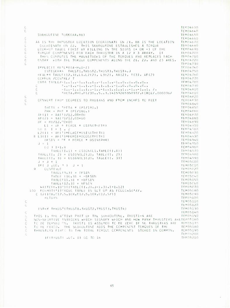
f. TEK04630 C TEM04640
SUbRuUTINt TuRK(AA.Hb) TEM046S0 C TFW04660 C AA IS THt rH"USTER LOCATION COORDINATE UN ZI, Bb IS THE LOCATION TEM04670 C COORDINATE UN LZ. THIS SUBROUTINE ESTABLISHES A TCRCUF TFM04680 C LOOK-UP TAül L FIRST bY FILLING IN THE SIGNS (• OR -I OF THE TF^0<.f,90 C TURCUF COMPONENTS FOR EACH THRUSTFR IN A 12 X 3 ARRAY. IT TFM04700 C THEN COMPUTES THE MAGNITUDtS OF THE TORCUES AND REPLACES EACH TEMOWIO C ENTRY MTH THt TURÜUE CUMPGNENTS ALONG THE IX, 12, AND Z3 AXES. TFM04720 C TEM04730
IMPLICIT RE*L*8(A-H.G-Z) TEM04740 INTEGER»'. TRLST1,TRGST2,TRUST3, TRUST*,, J TFN04750
RFAL*M TAL'LT ( 12, 3) ,L 1 ,L2(2) , L3(2), AAI2I» T(3), AF(?) TFM0A760 COMKGN /CCNTRL/ T TEM04770 [IATA TAHLE/-1.»l.i-l.t1.»l.i-l.fl.f-1.tO.tC.tO.iO.i TFM04780
C !.,-1.,-L.,1.,-1.,1.,l.,-1.,C.,0.,0.,C., TEM04790 C -l.t-l.t l.tl.t-1. t-l.tl. tl.tl.t-1.t-l.tl. /. TEM04800 C 'HETA,PHl,PI/30.,'>.,3.141,5926S35897/,FCRCE/.0000 36/ TFM 04810
G TEM04H20 C CONVERT TRUV DEGREES TO RAOUNS ANU F"GM INCHFS TC FEET TEM04R30 C TEM04840
IHCTR = 'HETA * (P1/1R0.) TEf'04850 PH« » PHl * (PI/lbC.) TFM04860
AF ( 1 ) • AA( 1 )/12.00 + nc) TEM04870 AF(2) = AA(^)/l2.0D+U0 TFM04880 HF = Hti/12.°D+00 TEN04890
Ll = uF * FüKCE * LiSIN(THETR) TEM04900 !.(] 8 1 = 1,2 TEM04910 L2(l) = AF( <)*fGHCE*DSIN(THtTR) TEM04920
8 LMI) = AF(')*FÜRCE*DC0S(THETR) TEN04930 BFSIN * PF * FORCt * USIN(PHR) TEM04940
.) = 1 TEM04950 IJ ) 1 = 1,8 TEM04960
TAALE(Itl) = DSIGML 1, TABLE ( 1 , 1 ) ) TEV04970 TAHLLII, 21 = USIGNIL2IJ), lABLrll, 2)) TEM0498D TABLFII, 3) = DSIGN(L3(J), TAoLElI, 31) TE*n<,990 J = J • 1 TEM05C00 IF( J .C.E. ' 1 J = 1 TEM03C10
9 CUNTIMUE TF^nstvn TAtiLL(9,3) = r.FSIN TEMO503O TABLE (10,3) = -BFSIN TEM05040 TARLE'11,3) = -bFSIN TEM05050 TAHLtll2,3) = bFSIN TEM05C60
WRITEI6, lO'M <(TABLE! I,J I ,J»1,3),1*1,12) TFN'05070 100 FORMAT!•1TTRCUE TAPLr IS SLT UP AS FCLLCWSO•//, TEM05080
C 121 10X,ni2.t>, 10X,012.5, 10X,f'.12.r)/) ) TEM0bC90 RtTiKN TErnsion
C TEM05110 C TE",OS120
FNTKY TH«UST(TRUST1,TKUST2,TROST i,TRUST4 ) TEMOSISO C TEM05140
THIS IS THt ArTIVt PART UF THL SUhROUTINL, TRUST1-4 ARE TEM05150 C NCN-NI »AUVE INTEGERS wHICH SIGNIFY WHICH ANO HOW PANY THRUSTFRS AKtTE^o* 160 C TO BE rURNFC r'N. TRUST1 IS ASSUMED TC PE ZERC IF NO THROSTtRS AR! TTV05170 C TO Ht FIRED. THE SUBROUTINE ADOS THE COMPONENT TORCUES OF THt TEVOSISO C THROSTLRS FIR'I) Tli THE TOTAL TCRQUE COMPONENTS STOREC IN COMMON. TEM05190 C TEV05200
IF!T-<UST1 .L-:. 0) GO TO 16 TEMOS210
45
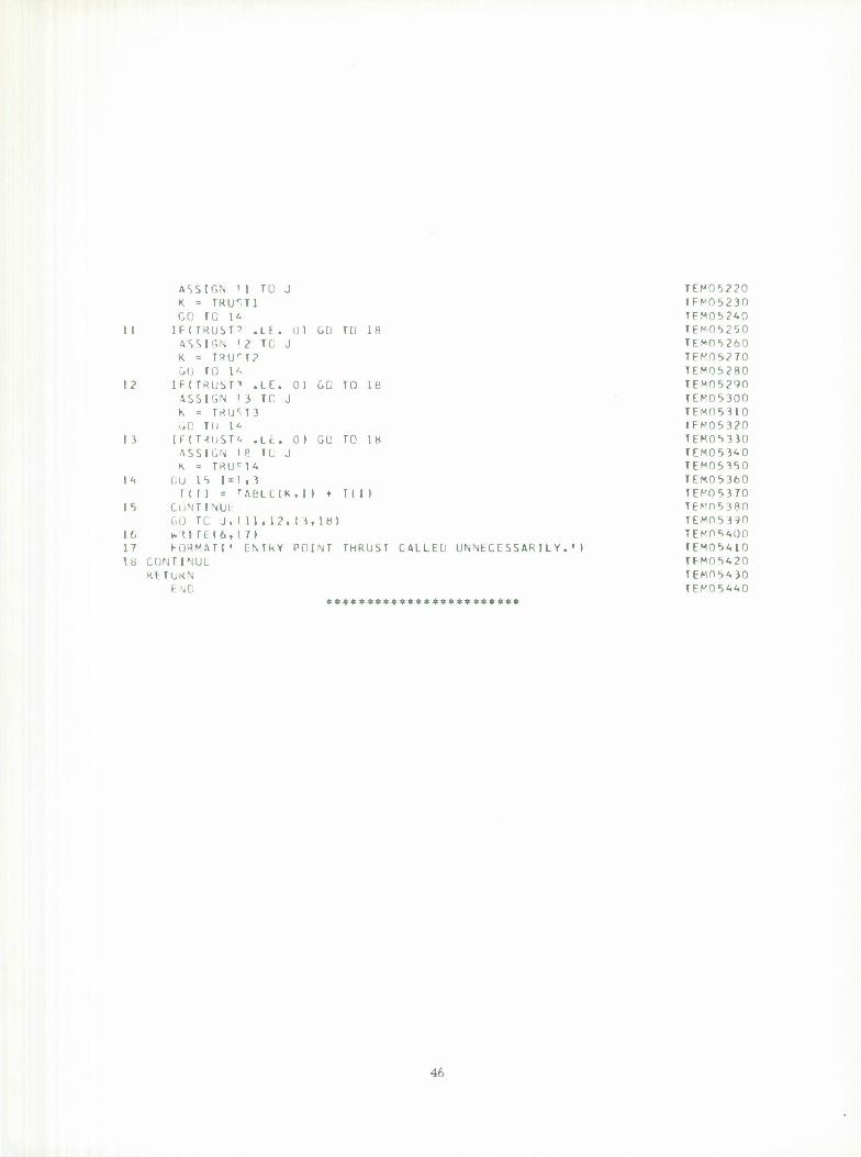
11
12
l *
14
15
\t, 1 t 18
ASSIGN 11 TO K = TKIT.TI cc ro i& IFITRUST'' .LF ASSIGN 12 TC J K » T«UrT2 GO TO l'i IFITRUSn .LE. 0)
J
0) CO TÜ 18
GO TO 18 ASSIGN 13 TO K = TRUM3 UQ TU It [F(T-<UST4 .LE. 01 GU TO 18 ASSIGN IP lü J K « mj*T<»
i;u 15 I «1,3 III) = TACLS;(K, I ) + T( I )
CONTINUE GO TC J, ( 1 1 , 12, M, 18) * < i r t. ( 6,17) FORMAT!• ENTRY POINT THRUST
CONTINUE KLTOKN
END ************************
CALLED UNNECESSARILY.' )
TFM05220 TFM05230 TEM052<Vn TEM05250 TEM05260 TFMOt>270 TEM05280 TEM05290 TEM05300 TFMO5310 TFM05320 TEMOS330 TEM05340 TEM05350 TEM05360 TEM05370 TEM053S0 TFMn5390 TFMDSAOO TEM0^>410 TFMITS420 TEMOb'.jn TFM054<.0
4h
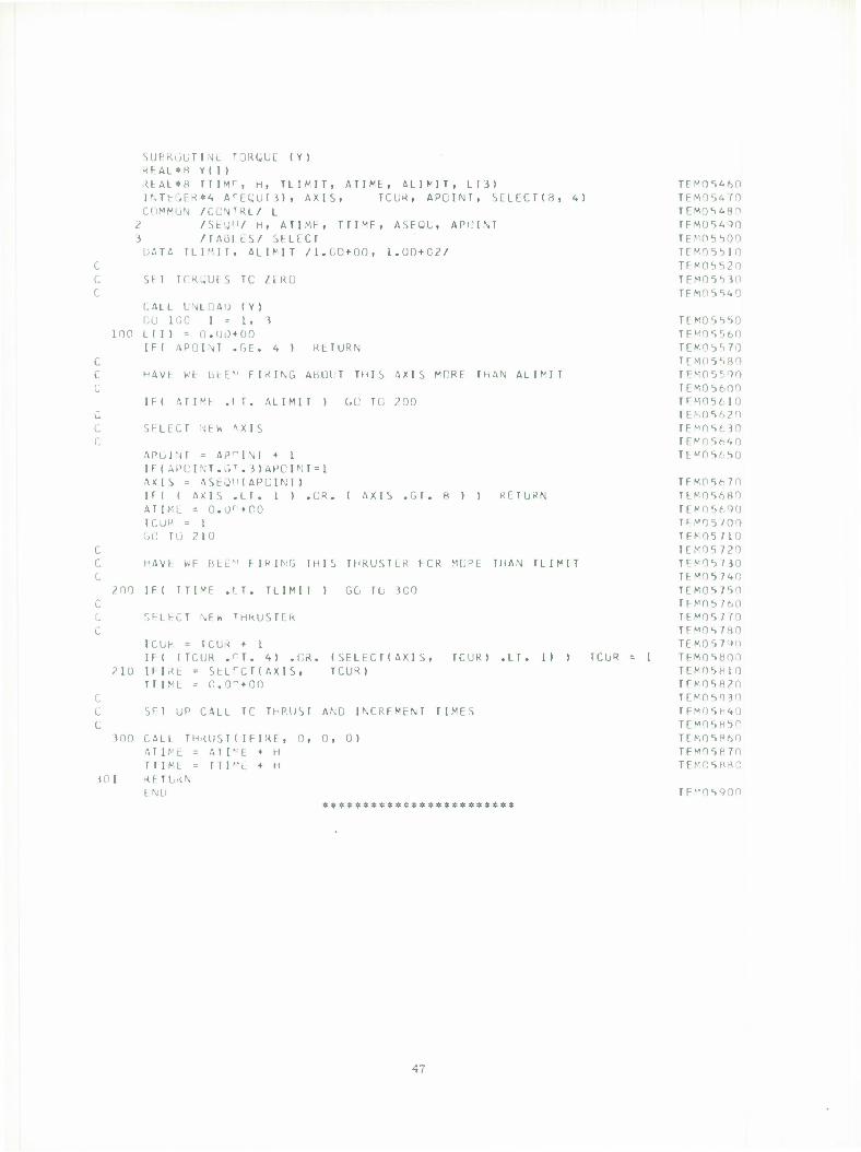
SURKÜUT l.ML TORCiLL (Y) KhAL*H Y(1) tEAL*8 TTIMT, H, TLIMIT, ATIME, ALIMIT, L(3) INTEGER**. ACE(„'U(3), AXIS, TCUR, APGINT, SCLECTI8, 4 ) COMMüN /CUNTRL/ L
2 /St'j"/ H, ATIME, TTtMF, ASFQL, APGINT 3 /TABI ES/ SFLFCT DATA TLIMIT. AHMT /l.CD+OO, L.OD+C2/
st i TGR^UES Tc /LRO
LALL UNLOAD (Y) CU IOC 1=1,3
100 L( 1 ) = 0.1)0+00 IF( APOINT .GE. 4 ) RETURN
HAVL WC bLE" FIRING AbUlT THIS AXIS MCRC ThAN ALIMT
IF( A T I Vt .IT. ALIMI T ) GG TG 200
SELECT '-JEW -. X I S
APUlNT = APGINT + 1 IT ( APCINT.G1". 3)AP0INT=1 AXIS = 4SE0IK APCINT) IF( ( AXIS .LT. 1 ) .CR. ATIME = Ü.O1 +C0 reu« = i GO Tu 210
( AXIS .GT. 8 ) ) RFTURN
HAVE WE BfcE*' FIRING THIS THRUSTLR FCR MC°E THAN TLIMIT
200 IFI TTI^F .IT. TLIMIT ) GO Tu 300
r,FLhCT \EW THKUSTCR
TCUR = TCUR • 1 1F( (TCUR .rT. 4) .GR. (SELECT!AXIS,
210 IFIRE = SELrCT(AXlS, TCUR) TTIML = 0.0"+00
TCUR) .LT. 1) ) TCUR
SFT UP CALL TC THRUST AND INCRFMFNT TIMES
300 CALL THRUST! IFIRE, 0, 0, 0) AT I ML = ATI"E + H TTIML = TTP'c + H
101 R£TURN ENU
TCM06460 TFM05470 TFM05480 TEM05490 TEMO5b00 TEMT5M0 TFMOSS?0 TEM05b30 TEMOS^O
TEKOSSSO TEM05560 TEM05 TCMOV.SO TEM05590 TEM05600 TFM05610 TEM0S620 TEW05630 TFM0S640 TEM05650
TFM0b670 TEM05680 TEM05690 TFM15700 TFM05710 IE MO 5 720 TEM05730 TEMO'57'VO TEM057SO TEMO5760 TEMO^ f TO TEM05780 TEK057'»0 TFM05800 TEM05H10 TEK05820 TEM05R30
TFMObH^O TEMOSH50 TEM05860 TFMO5870 TEM05880
TEM05900
47
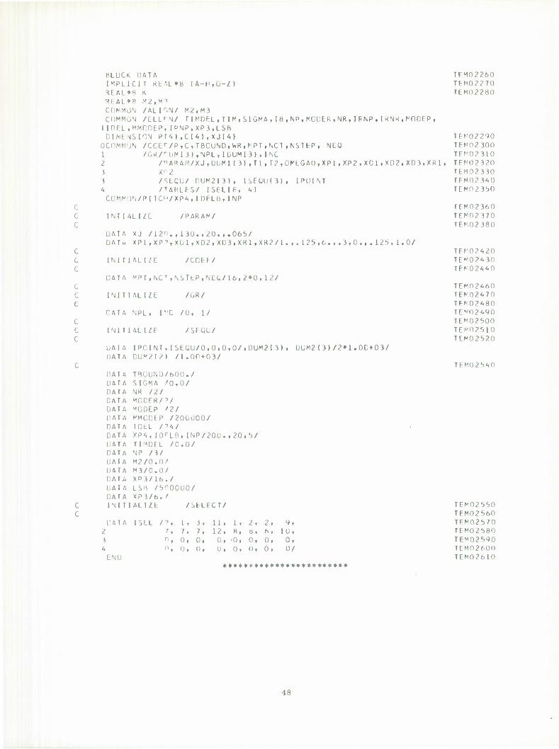
HLUCK DATA IMPLICIT REM-»8 (A-H.Ü-Z) REAL*8 K REAL*8 M2,M"< COMMLIN /ALI^.N/ M2.M3 COMMON /CLL^N/ TIMDFL,TIM,SIGMA,IB,NP,MODER,NR,IPNP,IRNR,MODEP, UDEL,MMCDEP,IPNP,XP3,LSB DIMENSION P(4),C(4),XJ(4)
OCOMMON /CCCr/P,C,TBOUND,WR,r'PT,NCT,NSTfcP, NEQ 1 /GR/rUM( 3),NPL, IDUMI 3) , INC 2 /"ARAM/XJ.DOMl (3) , T 1 , T2,OKEGAO , XP1,XP2,XD1,XD2,XD3,XR1 , 3 Xr'2 3 /SECU/ DUM2I3)i ISEQU«3)i IPOINT 4 /TABLES/ ISELI8, 4) COMMON/PITCH/XP4»IOELB.INP
I NT I Mill /PARAM/
DATA XJ /120., 130.,20.,.065/ DATM XP1,XP"',XU1,XD2,XD3,XRI,XR2/1.,.125,6.,.3,0.,.125,1.0/
INITIALIZE /COEF/
DATA MPT,NCTiNSTfcP,NEQ/16,2*0,12/
INITIALIZE /GR/
DATA NPL, PX /O, 1/
INITIALIZE /SEQL/
UAIA [POINT, I SEC.U/0,0,0,0/,ÜUM2I3) , DUM2(3)/2*1.OC+03/ DATA CUM2I2) /l.00+03/
DATA THÜUNÜ/600./ DATA SIGMA /O.O/ DATA NR 121 DATA MODER/"'/ DATA MODEP '2/ DATA MMCDEP /200000/ DATA mtL n<*i DATA XP4, lO^LB, INP/200.,20,5/ DATA TI.'IDEL /O.O/ DATA NP /3/ DATA M2/0.0/ DATA M3/0.0/ CAT« X P 3 / 16 . / DATA LSH /5PO0O0/ DATA XP3/6. /
c c
INITIALIZE /SELECT/
DATA 1SEL /', 1, 3, 11, 1, 2, 2, 9, 2 7, 7, 7, 12, 8, Ö, 6, 10, 1 n, 0, 0, 0, -0, 0, 0, 0,
•'« n, ü, Oi o, o, o, 0, 0/
TFM02260 TEM02270 TEM02280
TEM02290 TFM02 <00 TFM02310 TEMO2320 TEM02330 TEM02 340 TEMO 23 50
TEM02360 TEM02370 TFM02380
TEM0242O TF"02A JO TFM024 40
TEM02460 TFM02A70 TFM02A80 TEM02A90 TEM02500 TEM02510 TEM02520
TEM025 40
END
TEf02550 TFM02560 TFV025 TO TEM02580 TEM02590 TEM02600 TEM02610
«ft**********************
48
SUbKUUTINC '"•Kl (FK.X, Y) DIMENSION X f 1) , Y < 1 ) INTCGFR bbG'N.FS COMMON ^GR/Yt,XRfYBfYr,OX, CY, NPL,NDO,NPT,tEGIN,INC
FIND UPP2R AND I OV»ER GRID LIMITS CALL MINMAX(Y,NPLfYBiYT) IF (YB) IC'O^O
10 YH=1.05*YB GO TU 3Ü
20 YH=0.9S*Yb 30 CONTINUE
IF ( YT ) «.C-O.iO <»0 YT = 0.9">*YT
GO TU 60 SO YT*1,05*YT 60 CON IINUF
BEGIN«! XL-XI1) OY=tYT-YB)/10.
IS MURE THAN LNr FRAME OESIRED IF (FR.CT. 1 ) GO TO 80
ENTIRE GRAPH TU LE PLCTTLÜ UN ONE NPT=NPL XR = X(NPL) GX-IXR-XD/'O. Nf)U = UEGIN*(• PT- 1 l*INC-l CALL G«2(X,v) KtTU-lN
FRAMt.
GRAPH 80
IG BE
,0) NPLFR=NPLFR+1
PLOTTED UN MORE THAN LINE FRAME. IfKl=FK-l MPLI ,< = MPL + fFRl)/FR IF (MODINPL+IFRI.FRI.NE, NPT=NPLFR NM1»NPLFK-1
DX*(XINPT)-vL)/20.
1 MtS. PLUT INITIAL FR DXR*20.*0X XK=XL+DXR DO 90 1 = 1»Ir K 1 IX=I NDü*rtEGIN+r'PT-l )*INL-1 CALL GR?(X,Y) XL = XR XR=XR»C<R BEGIN«BEGIN+NM1 IT (XR.GE.X(NPL)I GÜ TO
»0 COM INUfc
PLUT f INAL TRAMr. DO NPT* JPL-I X*":ML
NOO=aEGIN+(" PT-1)*INC-1 CALL GR2(X,V) R1 TURN END
100
TEM03I00 TEM03110 TEMO3120
TEM031A0 TEM03150 TEM03160 TEV0 3L70 TEMO 3180 TCM03190 TEM03200 TEM03210 TFM03220 TFM03230 TEM03240 TEM03250 TEM03260 TEMO3270 TEM03280 TFM03290 TEM03300 TFM03310 TFMD3320 TEf'03330 TEK03340 TEM033S0 TFM03360 TEM03370 TFM03A10 TFM03420 TEM03430 TEM03A40 TEM03450 TEM03460 TEM03470 TEM03<.nn Tl" wn3490 TEMO3500 TEM03blO TEMO3b40 TCMO JSSO TEMO3560 TEMO JWO TEM0358O TEMO3590 TCM03600 TFM03610 TEMO 3620 TEK03630 TCM03640 TEM03650 TEM03660 TEMO3670 TEM03680 TFM03690 TEM03700 TEM03710 TEM03720 TEN03730
40
1 2 i
10
SUb DIM XMI XMA DU IF XMI IF XMA
CON
KtfT
END
KOU b MS N = X = 10 tx( N « ( XM X = TIN UHN
TINt "INMAX ION xr l) X( 1 I X( l)
1=2, N I 1-XMIN) XI I )
AX-XI T ) ) X( I )
UF
(X, N, XMIN, XMAX )
1,2,2
3,10,10
*********«***»$«»»$»**»*
TEMO TEMO TEMO TEMO TEMO TEMO TEMO TEMO TEMO TEMO TEMO TEMO
3870 3880 3890 3900 3910 3920 39 30 3940 39S0 3960 3970 3980
SO
UNCLASSIFIED Security Classification
DOCUMENT CONTROL DATA - R&D (Security classification ot title, body of abstract and indexing annotation must be entered when the overall report is ctmaattlad)
I. ORIGINATING ACTIVITY (Corporate author)
Lincoln Laboratory, M.I.T.
2a. REPORT SECURITY CLASSIFICATION
Unclassified 2b. GROUP
None 3. REPORT TITLE
LES-8/9 Attitude Control System Numerical Simulation
4. DESCRIPTIVE NOTES (Type ot report and inclusive dates)
Technical Note
5. AUTHOR(S) (Last name, first name, initial)
Floyd, Franklin W. Much, Carl H. Smith, Norval P. Swenson, Ellen H.
6. REPORT DATE
5 February 1471 la. TOTAL NO. OF PAGES
58 7b. NO. OF REFS
5
8a. CONTRACT OR GRANT NO. Fl 9628 -70-C "0230
b. PROJECT NO. 649L
9a. ORIGINATOR'S REPORT NUMBERISI
Technical Note 1971-10
9b. OTHER REPORT NO(S) (Any other numbers that may be assigned this report)
ESD-TR-71-11
10. AVAILABILITY/LIMITATION NOTICES
Approved for public release; distribution unlimited.
11. SUPPLEMENTARY NOTES
None
12. SPONSORING MILITARY ACTIVITY
Air Force Systems Command, USAF
13. ABSTRACT
A program was written to simulate the three axis attitude control system of LES-8/9. The underlying theory to the computer simulation and detailed outlines of each of the subroutines in- volved in the complete program are described.
Whenever feasible, the simulation was written to duplicate as closely as possible the logic and signal flow of the actual digital attitude control system. Each subroutine was thoroughly verified as accurate by independent and integral system operation, as well as by theoretical es- timates, analog computer simulations and actual experimental data.
A substantial compilation of data from this working program was catalogued and analyzed for attitude control system evaluation and optimization. This program also proved itself to be invaluable in the analysis of stability and performance of the complete attitude control system.
14. KEY WORDS
LES analog computer simulation
digital attitude control system satellite
51 UNCLASSIFIED Security Classification