Embed Size (px)
Citation preview
book.book Page 1 Wednesday, April 15, 2009 8:47 PM
Dell™ PowerEdge™ T105 Systems
Hardware Owner’s Manual
w w w . d e l l . c o m | s u p p o r t . d e l l . c o m
book.book Page 2 Wednesday, April 15, 2009 8:47 PM
Notes, Notices, and Cautions NOTE: A NOTE indicates important information that helps you make better use of
your computer.
NOTICE: A NOTICE indicates either potential damage to hardware or loss of data
and tells you how to avoid the problem.
CAUTION: A CAUTION indicates a potential for property damage, personal injury,
or death.
____________________
Information in this document is subject to change without notice.© 2007-2009 Dell Inc. All rights reserved.
Reproduction in any manner whatsoever without the written permission of Dell Inc. is strictly forbidden.
Trademarks used in this text: Dell, the DELL logo, Inspiron, Dell Precision, Dimension, OptiPlex, Latitude, PowerEdge, PowerVault, PowerApp, PowerConnect, XPS, and Dell OpenManage are trademarks of Dell Inc.; Microsoft, MS-DOS, Windows, and Windows Server are either trademarks or registered trademarks of Microsoft Corporation in the United States and/or other countries; Red Hat is a registered trademark of Red Hat, Inc.; UNIX is a registered trademark of The Open Group in the United States and other countries; EMC is a registered trademark of EMC Corporation.
Other trademarks and trade names may be used in this document to refer to either the entities claiming the marks and names or their products. Dell Inc. disclaims any proprietary interest in trademarks and trade names other than its own.
March 2009 P/N JN551 Rev. A01
book.book Page 3 Wednesday, April 15, 2009 8:47 PM
Contents
1 About Your System . . . . . . . . . . . . . . . . . . 11
Other Information You May Need . . . . . . . . . . . . 11
Accessing System Features During Startup . . . . . . . 12
Front-Panel Features and Indicators . . . . . . . . . . 13
Back-Panel Features and Indicators . . . . . . . . . . 15
Connecting External Devices . . . . . . . . . . . . 16
NIC Indicator Codes . . . . . . . . . . . . . . . . 16
Power Supply Indicators . . . . . . . . . . . . . . 17
Diagnostic Lights . . . . . . . . . . . . . . . . . . . . 18
System Messages . . . . . . . . . . . . . . . . . . . . 20
Warning Messages . . . . . . . . . . . . . . . . . . . 29
Diagnostics Messages . . . . . . . . . . . . . . . . . 29
Alert Messages . . . . . . . . . . . . . . . . . . . . . 30
2 Using the System Setup Program . . . . . . 31
Entering the System Setup Program . . . . . . . . . . . 31
Responding to Error Messages. . . . . . . . . . . 31
Using the System Setup Program . . . . . . . . . 32
Exiting the System Setup Program . . . . . . . . . . . 33
Contents 3
book.book Page 4 Wednesday, April 15, 2009 8:47 PM
System Setup Options . . . . . . . . . . . . . . . . . . 33
Main Screen . . . . . . . . . . . . . . . . . . . . 33
Memory Information Screen . . . . . . . . . . . . 35
CPU Information Screen . . . . . . . . . . . . . . 36
SATA Configuration Screen . . . . . . . . . . . . . 36
Integrated Devices Screen . . . . . . . . . . . . . 37
System Security Screen . . . . . . . . . . . . . . 38
Exit Screen . . . . . . . . . . . . . . . . . . . . . 39
System and Setup Password Features. . . . . . . . . . 39
Using the System Password . . . . . . . . . . . . 40
Using the Setup Password . . . . . . . . . . . . . 42
Disabling a Forgotten Password . . . . . . . . . . 43
3 Installing System Components . . . . . . . 45
Recommended Tools . . . . . . . . . . . . . . . . . . . 45
Inside the System. . . . . . . . . . . . . . . . . . . . . 46
Opening the System . . . . . . . . . . . . . . . . . . . 47
Closing the System . . . . . . . . . . . . . . . . . . . . 47
Front Drive Bezel . . . . . . . . . . . . . . . . . . . . . 48
Removing the Front Drive Bezel . . . . . . . . . . 49
Replacing the Front Drive Bezel . . . . . . . . . . 49
Removing an Insert on the Front Drive Bezel . . . . 50
Replacing an Insert on the Front Drive Bezel. . . . 50
Removing and Inserting Blank Drive Inserts . . . . . . 51
Diskette Drive . . . . . . . . . . . . . . . . . . . . . . 52
Removing the Diskette Drive . . . . . . . . . . . . 52
Installing a Diskette Drive. . . . . . . . . . . . . . 54
4 Contents
book.book Page 5 Wednesday, April 15, 2009 8:47 PM
Optical and Tape Drives . . . . . . . . . . . . . . . . . 57
Removing an Optical or Tape Drive. . . . . . . . . 57
Installing an Optical or Tape Drive . . . . . . . . . 60
Hard Drives. . . . . . . . . . . . . . . . . . . . . . . . 64
Hard Drive Installation Guidelines . . . . . . . . . 64
Removing a Hard Drive . . . . . . . . . . . . . . . 64
Installing a Hard Drive . . . . . . . . . . . . . . . 66
Expansion Cards . . . . . . . . . . . . . . . . . . . . . 70
Removing an Expansion Card . . . . . . . . . . . 70
Installing an Expansion Card . . . . . . . . . . . . 72
SAS Controller Expansion Card . . . . . . . . . . 73
Memory . . . . . . . . . . . . . . . . . . . . . . . . . 75
Memory Module Upgrade Kits . . . . . . . . . . . 75
Memory Module Installation Guidelines . . . . . . 75
Addressing Memory With 8-GB Configurations
(Microsoft® Windows® Operating
System Only) . . . . . . . . . . . . . . . . . . . . 76
Removing a Memory Module . . . . . . . . . . . . 77
Installing a Memory Module . . . . . . . . . . . . 77
Microprocessor . . . . . . . . . . . . . . . . . . . . . 79
Removing the Processor . . . . . . . . . . . . . . 79
Replacing the Processor . . . . . . . . . . . . . . 82
Cooling Fans . . . . . . . . . . . . . . . . . . . . . . . 83
Removing the Cooling Fans . . . . . . . . . . . . . 84
Replacing the Cooling Fans. . . . . . . . . . . . . 86
System Battery . . . . . . . . . . . . . . . . . . . . . . 88
Removing the System Battery . . . . . . . . . . . 89
Installing the System Battery . . . . . . . . . . . . 90
Contents 5
book.book Page 6 Wednesday, April 15, 2009 8:47 PM
Power Supply . . . . . . . . . . . . . . . . . . . . . . 91
Removing the Power Supply . . . . . . . . . . . . 91
Installing the Power Supply. . . . . . . . . . . . . 93
Chassis Intrusion Switch . . . . . . . . . . . . . . . . 93
Removing the Chassis Intrusion Switch . . . . . . 93
Installing the Chassis Intrusion Switch . . . . . . . 94
Bezel (Service Only Parts Procedure) . . . . . . . . . . 95
Removing the Bezel . . . . . . . . . . . . . . . . . 95
Replacing the Bezel . . . . . . . . . . . . . . . . . 96
I/O Panel Assembly (Service Only Parts
Procedure) . . . . . . . . . . . . . . . . . . . . . . . . 97
Removing the I/O Panel Assembly . . . . . . . . . 97
Replacing the I/O Panel Assembly . . . . . . . . . 98
System Board (Service Only Parts Procedure) . . . . 100
Removing the System Board . . . . . . . . . . . 100
Installing the System Board. . . . . . . . . . . . 101
4 Troubleshooting Your System . . . . . . . . 103
Safety First—For You and Your System . . . . . . . . 103
Start-Up Routine . . . . . . . . . . . . . . . . . . . . 103
Checking the Equipment . . . . . . . . . . . . . . . . 104
Troubleshooting External Connections . . . . . . 104
Troubleshooting the Video Subsystem . . . . . . 104
Troubleshooting the Keyboard . . . . . . . . . . 105
Troubleshooting the Mouse. . . . . . . . . . . . 105
Troubleshooting Serial I/O Problems . . . . . . . . . 106
Troubleshooting a Serial I/O Device . . . . . . . 107
Troubleshooting a USB Device . . . . . . . . . . 107
6 Contents
book.book Page 7 Wednesday, April 15, 2009 8:47 PM
Troubleshooting a NIC . . . . . . . . . . . . . . . . . . 108
Troubleshooting a Wet System . . . . . . . . . . . . . 109
Troubleshooting a Damaged System . . . . . . . . . . 110
Troubleshooting the System Battery. . . . . . . . . . . 111
Troubleshooting Power Supply . . . . . . . . . . . . . 112
Troubleshooting System Cooling Problems . . . . . . . 113
Troubleshooting a Fan . . . . . . . . . . . . . . . 113
Troubleshooting System Memory . . . . . . . . . . . . 114
Troubleshooting a Diskette Drive . . . . . . . . . . . . 116
Troubleshooting an Optical Drive . . . . . . . . . . . . 118
Troubleshooting an External SCSI Tape Drive . . . . . 119
Troubleshooting a Hard Drive . . . . . . . . . . . . . . 120
Troubleshooting a SAS or SAS RAID Controller . . . . 122
Troubleshooting Expansion Cards . . . . . . . . . . . . 123
Troubleshooting the Microprocessor . . . . . . . . . . 125
5 Running the System Diagnostics . . . . . . 127
Using Dell PowerEdge Diagnostics . . . . . . . . . . . 127
System Diagnostics Features . . . . . . . . . . . . . . 127
When to Use the System Diagnostics . . . . . . . . . . 128
Running the System Diagnostics . . . . . . . . . . . . 128
System Diagnostics Testing Options . . . . . . . . . . 128
Contents 7
book.book Page 8 Wednesday, April 15, 2009 8:47 PM
Using the Custom Test Options . . . . . . . . . . . . 129
Selecting Devices for Testing . . . . . . . . . . . 129
Selecting Diagnostics Options . . . . . . . . . . 129
Viewing Information and Results . . . . . . . . . 130
6 Jumpers and Connectors . . . . . . . . . . . . 131
System Board Jumpers. . . . . . . . . . . . . . . . . 131
System Board Connectors . . . . . . . . . . . . . . . 133
Disabling a Forgotten Password. . . . . . . . . . . . 135
7 Getting Help . . . . . . . . . . . . . . . . . . . . . . 137
Obtaining Assistance . . . . . . . . . . . . . . . . . 137
Online Services . . . . . . . . . . . . . . . . . . 138
Automated Order-Status Service . . . . . . . . . 139
Support Service . . . . . . . . . . . . . . . . . . 139
Dell Enterprise Training and Certification. . . . . . . 139
Problems With Your Order . . . . . . . . . . . . . . . 139
Product Information . . . . . . . . . . . . . . . . . . 139
Returning Items for Warranty Repair or Credit . . . . 140
Before You Call . . . . . . . . . . . . . . . . . . . . . 140
Contacting Dell . . . . . . . . . . . . . . . . . . . . . 142
8 Contents

book.book Page 9 Wednesday, April 15, 2009 8:47 PM
Glossary . . . . . . . . . . . . . . . . . . . . . . . . . . . . 173
Index . . . . . . . . . . . . . . . . . . . . . . . . . . . . . . 185
Contents 9

book.book Page 10 Wednesday, April 15, 2009 8:47 PM
10 Contents
book.book Page 11 Wednesday, April 15, 2009 8:47 PM
About Your SystemThis section describes the physical, firmware, and software interface features that provide and ensure the essential functioning of your system. The physical connectors on your system’s front and back panels provide convenient connectivity and system expansion capability. The system firmware, applications, and operating systems monitor the system and component status and alert you when a problem arises. System conditions can be reported by any of the following:
• Front or back panel indicators
• System messages
• Warning messages
• Diagnostics messages
• Alert messages
This section describes each type of message, lists the possible causes, and provides steps to resolve any problems indicated by a message. The system indicators and features are illustrated in this section.
Other Information You May Need CAUTION: The Product Information Guide provides important safety and
regulatory information. Warranty information may be included within this
document or as a separate document.
• The Getting Started Guide provides an overview of system features, setting up your system, and technical specifications.
• CDs included with your system provide documentation and tools for configuring and managing your system.
• Systems management software documentation describes the features, requirements, installation, and basic operation of the software.
• Operating system documentation describes how to install (if necessary), configure, and use the operating system software.
• Documentation for any components you purchased separately provides information to configure and install these options.
About Your System 11
book.book Page 12 Wednesday, April 15, 2009 8:47 PM
• Updates are sometimes included with the system to describe changes to the system, software, and/or documentation.
NOTE: Always check for updates on support.dell.com and read the updates
first because they often supersede information in other documents.
• Release notes or readme files may be included to provide last-minute updates to the system or documentation or advanced technical reference material intended for experienced users or technicians.
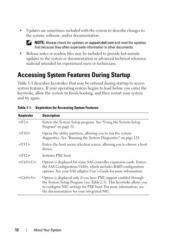
Accessing System Features During StartupTable 1-1 describes keystrokes that may be entered during startup to access system features. If your operating system begins to load before you enter the keystroke, allow the system to finish booting, and then restart your system and try again.
Table 1-1. Keystrokes for Accessing System Features
Keystroke Description
<F2> Enters the System Setup program. See "Using the System Setup Program" on page 31.
<F10> Opens the utility partition, allowing you to run the system diagnostics. See "Running the System Diagnostics" on page 128.
<F11> Enters the boot menu selection screen, allowing you to choose a boot device.
<F12> Initiates PXE boot.
<Ctrl+C> Option is displayed for some SAS controller expansion cards. Enters the SAS Configuration Utility, which includes RAID configuration options. See your SAS adapter User’s Guide for more information.
<Ctrl+S> Option is displayed only if you have PXE support enabled through the System Setup Program (see Table 2-1). This keystroke allows you to configure NIC settings for PXE boot. For more information, see the documentation for your integrated NIC.
12 About Your System
book.book Page 13 Wednesday, April 15, 2009 8:47 PM
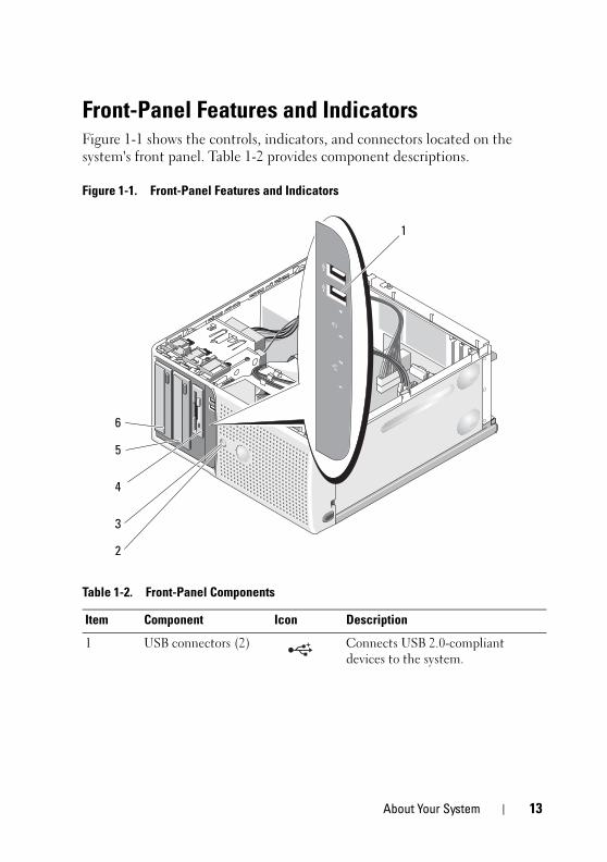
Front-Panel Features and IndicatorsFigure 1-1 shows the controls, indicators, and connectors located on the system's front panel. Table 1-2 provides component descriptions.
Figure 1-1. Front-Panel Features and Indicators
Table 1-2. Front-Panel Components
Item Component Icon Description
1 USB connectors (2) Connects USB 2.0-compliant devices to the system.
1
2
3
5
6
4
About Your System 13
book.book Page 14 Wednesday, April 15, 2009 8:47 PM
2 power button The power button controls the DC power supply output to the system.
NOTE: If you turn off the system using
the power button and the system is
running an ACPI-compliant operating
system, the system performs a
graceful shutdown before the power
is turned off. If the system is not
running an ACPI-compliant operating
system, the power is turned off
immediately after the power button is
pressed.
3 power light No light — The system is off.
Steady green — The system is powered on.
Blinking green — The system is in a low power state.
Steady amber — A BIOS failure occurred before Power-On Self Test (POST). See "Diagnostic Lights" on page 18.
Blinking amber — There is a problem with the power supply.
4 flex bay Holds an optional diskette drive.
5 lower 5.25-inch drive bay
Holds an optional optical or tape backup unit drive.
6 upper 5.25-inch drive bay
Holds an optical drive.
Table 1-2. Front-Panel Components (continued)
Item Component Icon Description
14 About Your System
book.book Page 15 Wednesday, April 15, 2009 8:47 PM
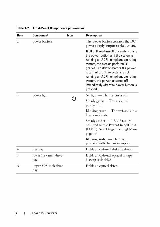
Back-Panel Features and IndicatorsFigure 1-2 shows the controls, indicators, and connectors located on the system's back panel.
Figure 1-2. Back-Panel Features and Indicators
1 voltage selection switch 2 power connector
3 USB connectors (5) 4 NIC connector
5 video connector 6 serial connector
7 I/O expansion-card slots (4)
1
5
7
4
3
2
6
About Your System 15
book.book Page 16 Wednesday, April 15, 2009 8:47 PM
Connecting External Devices
When connecting external devices to your system, follow these guidelines:
• Most devices must be connected to a specific connector and device drivers must be installed before the device operates properly. (Device drivers are normally included with your operating system software or with the device itself.) See the documentation that accompanied the device for specific installation and configuration instructions.
• Always attach an external device while your system and the device are turned off. Next, turn on any external devices before turning on the system (unless the documentation for the device specifies otherwise).
See "Using the System Setup Program" on page 31 for information about enabling, disabling, and configuring I/O ports and connectors.
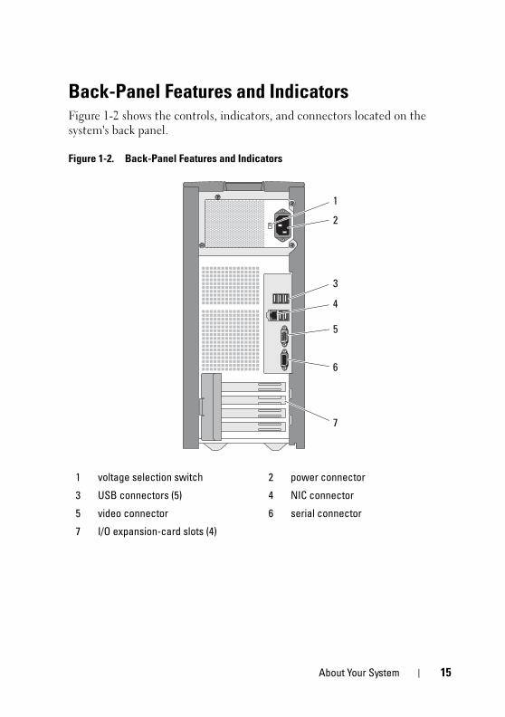
NIC Indicator Codes
The NIC on the back panel has an indicator that provides information on network activity and link status. See Figure 1-3. Table 1-3 lists the NIC indicator codes.
Figure 1-3. NIC Indicators
1 link indicator 2 activity indicator
1 2
16 About Your System
book.book Page 17 Wednesday, April 15, 2009 8:47 PM
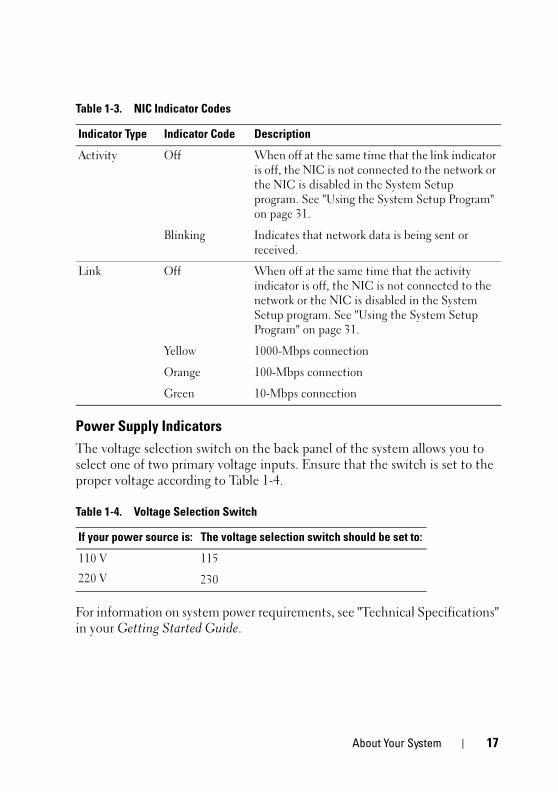
Power Supply Indicators
The voltage selection switch on the back panel of the system allows you to select one of two primary voltage inputs. Ensure that the switch is set to the proper voltage according to Table 1-4.
For information on system power requirements, see "Technical Specifications" in your Getting Started Guide.
Table 1-3. NIC Indicator Codes
Indicator Type Indicator Code Description
Activity Off When off at the same time that the link indicator is off, the NIC is not connected to the network or the NIC is disabled in the System Setup program. See "Using the System Setup Program" on page 31.
Blinking Indicates that network data is being sent or received.
Link Off When off at the same time that the activity indicator is off, the NIC is not connected to the network or the NIC is disabled in the System Setup program. See "Using the System Setup Program" on page 31.
Yellow 1000-Mbps connection
Orange 100-Mbps connection
Green 10-Mbps connection
Table 1-4. Voltage Selection Switch
If your power source is: The voltage selection switch should be set to:
110 V
220 V
115
230
About Your System 17
book.book Page 18 Wednesday, April 15, 2009 8:47 PM
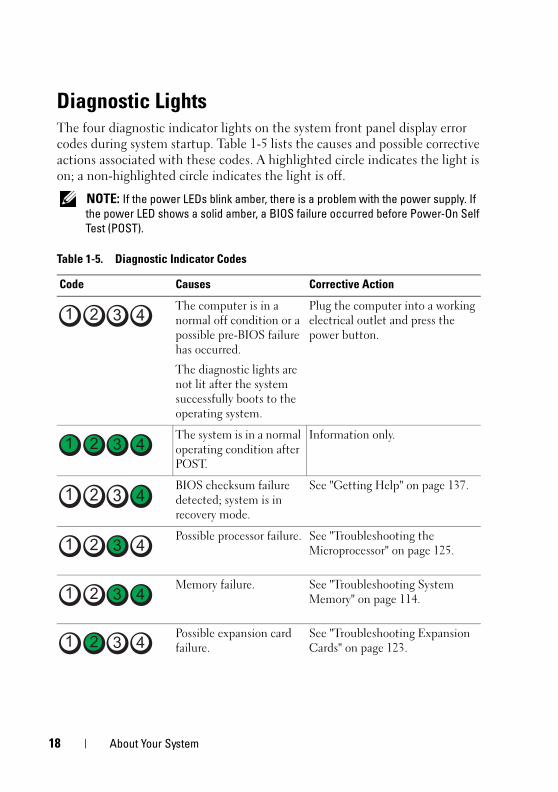
Diagnostic LightsThe four diagnostic indicator lights on the system front panel display error codes during system startup. Table 1-5 lists the causes and possible corrective actions associated with these codes. A highlighted circle indicates the light is on; a non-highlighted circle indicates the light is off.
NOTE: If the power LEDs blink amber, there is a problem with the power supply. If
the power LED shows a solid amber, a BIOS failure occurred before Power-On Self
Test (POST).
Table 1-5. Diagnostic Indicator Codes
Code Causes Corrective Action
The computer is in a normal off condition or a possible pre-BIOS failure has occurred.
The diagnostic lights are not lit after the system successfully boots to the operating system.
Plug the computer into a working electrical outlet and press the power button.
The system is in a normal operating condition after POST.
Information only.
BIOS checksum failure detected; system is in recovery mode.
See "Getting Help" on page 137.
Possible processor failure. See "Troubleshooting the Microprocessor" on page 125.
Memory failure. See "Troubleshooting System Memory" on page 114.
Possible expansion card failure.
See "Troubleshooting Expansion Cards" on page 123.
18 About Your System
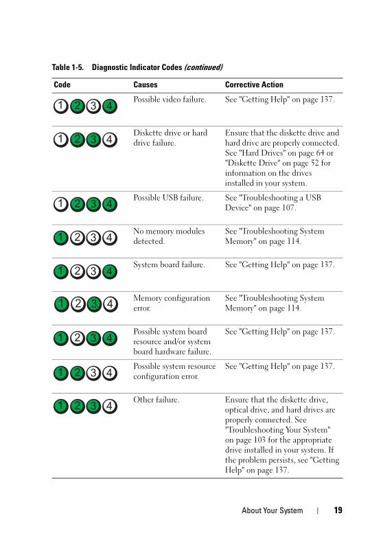
book.book Page 19 Wednesday, April 15, 2009 8:47 PM
Possible video failure. See "Getting Help" on page 137.
Diskette drive or hard drive failure.
Ensure that the diskette drive and hard drive are properly connected. See "Hard Drives" on page 64 or "Diskette Drive" on page 52 for information on the drives installed in your system.
Possible USB failure. See "Troubleshooting a USB Device" on page 107.
No memory modules detected.
See "Troubleshooting System Memory" on page 114.
System board failure. See "Getting Help" on page 137.
Memory configuration error.
See "Troubleshooting System Memory" on page 114.
Possible system board resource and/or system board hardware failure.
See "Getting Help" on page 137.
Possible system resource configuration error.
See "Getting Help" on page 137.
Other failure. Ensure that the diskette drive, optical drive, and hard drives are properly connected. See "Troubleshooting Your System" on page 103 for the appropriate drive installed in your system. If the problem persists, see "Getting Help" on page 137.
Table 1-5. Diagnostic Indicator Codes (continued)
Code Causes Corrective Action
About Your System 19
book.book Page 20 Wednesday, April 15, 2009 8:47 PM
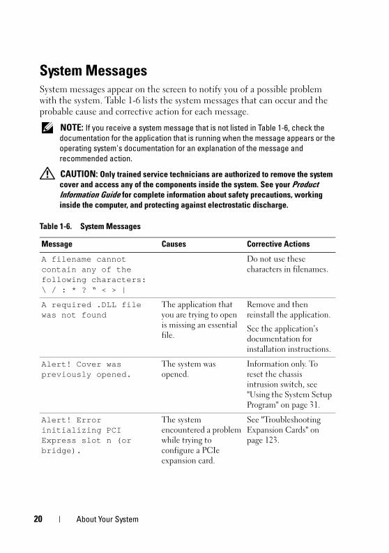
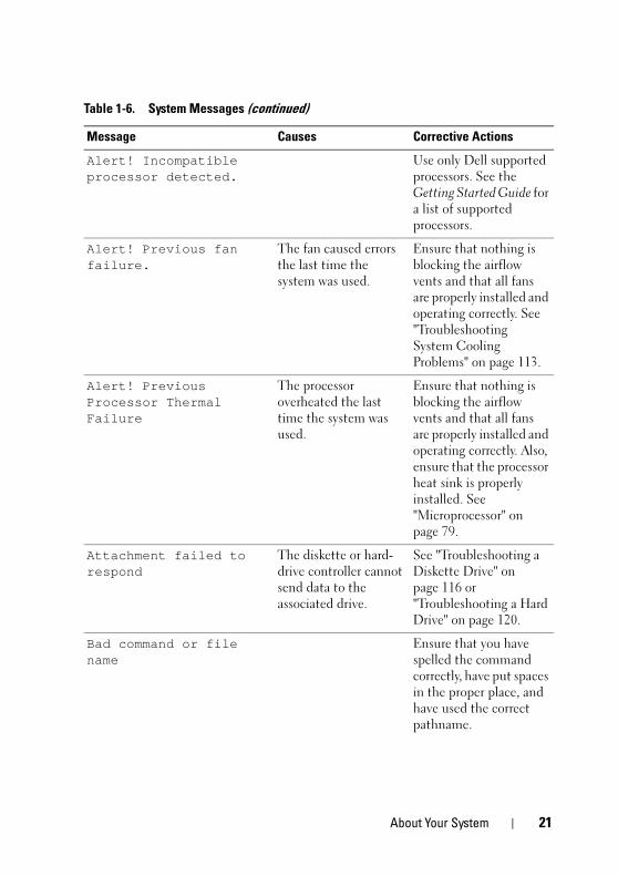
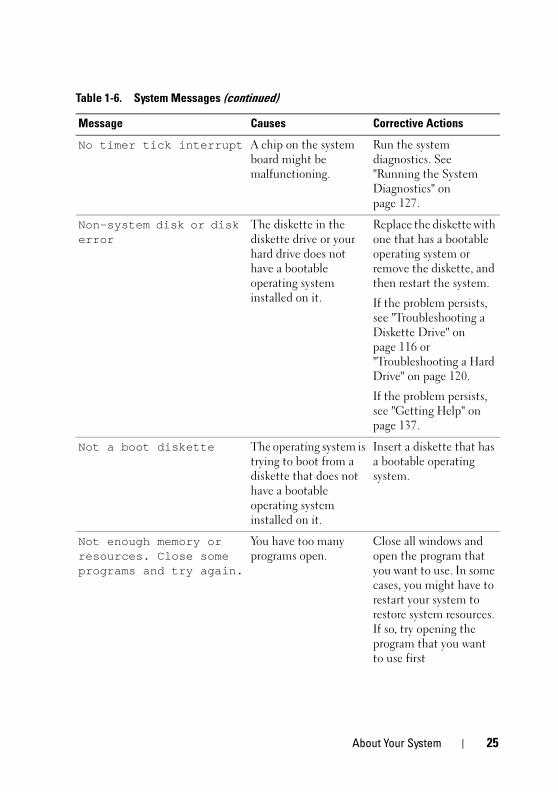
System MessagesSystem messages appear on the screen to notify you of a possible problem with the system. Table 1-6 lists the system messages that can occur and the probable cause and corrective action for each message.
NOTE: If you receive a system message that is not listed in Table 1-6, check the
documentation for the application that is running when the message appears or the
operating system's documentation for an explanation of the message and
recommended action.
CAUTION: Only trained service technicians are authorized to remove the system
cover and access any of the components inside the system. See your Product
Information Guide for complete information about safety precautions, working
inside the computer, and protecting against electrostatic discharge.
Table 1-6. System Messages
Message Causes Corrective Actions
A filename cannot contain any of the following characters: \ / : * ? “ < > |
Do not use these characters in filenames.
A required .DLL file was not found
The application that you are trying to open is missing an essential file.
Remove and then reinstall the application.
See the application’s documentation for installation instructions.
Alert! Cover was previously opened.
The system was opened.
Information only. To reset the chassis intrusion switch, see "Using the System Setup Program" on page 31.
Alert! Error initializing PCI Express slot n (or bridge).
The system encountered a problem while trying to configure a PCIe expansion card.
See "Troubleshooting Expansion Cards" on page 123.
20 About Your System
book.book Page 21 Wednesday, April 15, 2009 8:47 PM
Alert! Incompatible processor detected.
Use only Dell supported processors. See the Getting Started Guide for a list of supported processors.
Alert! Previous fan failure.
The fan caused errors the last time the system was used.
Ensure that nothing is blocking the airflow vents and that all fans are properly installed and operating correctly. See "Troubleshooting System Cooling Problems" on page 113.
Alert! Previous Processor Thermal Failure
The processor overheated the last time the system was used.
Ensure that nothing is blocking the airflow vents and that all fans are properly installed and operating correctly. Also, ensure that the processor heat sink is properly installed. See "Microprocessor" on page 79.
Attachment failed to respond
The diskette or hard-drive controller cannot send data to the associated drive.
See "Troubleshooting a Diskette Drive" on page 116 or "Troubleshooting a Hard Drive" on page 120.
Bad command or file name
Ensure that you have spelled the command correctly, have put spaces in the proper place, and have used the correct pathname.
Table 1-6. System Messages (continued)
Message Causes Corrective Actions
About Your System 21
book.book Page 22 Wednesday, April 15, 2009 8:47 PM
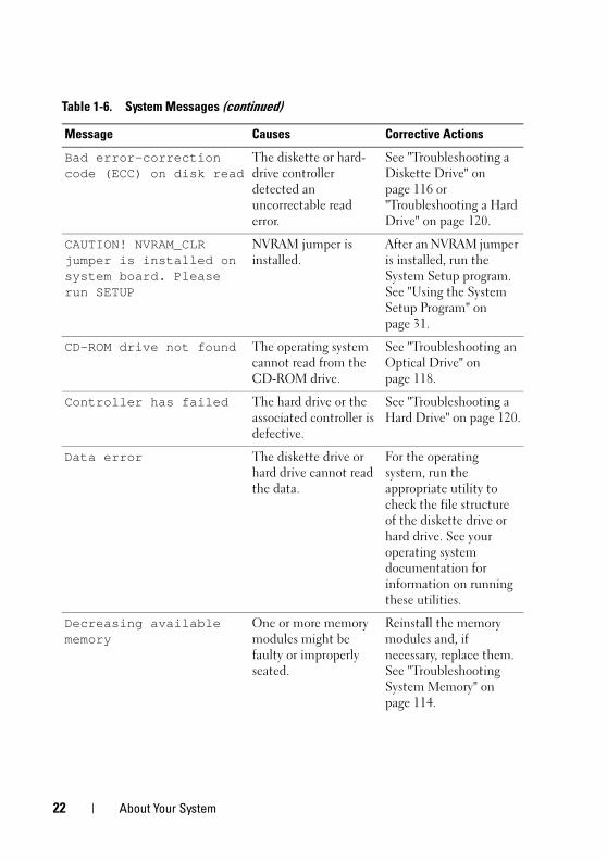
Bad error-correction code (ECC) on disk read
The diskette or hard-drive controller detected an uncorrectable read error.
See "Troubleshooting a Diskette Drive" on page 116 or "Troubleshooting a Hard Drive" on page 120.
CAUTION! NVRAM_CLR jumper is installed on system board. Please run SETUP
NVRAM jumper is installed.
After an NVRAM jumper is installed, run the System Setup program. See "Using the System Setup Program" on page 31.
CD-ROM drive not found The operating system cannot read from the CD-ROM drive.
See "Troubleshooting an Optical Drive" on page 118.
Controller has failed The hard drive or the associated controller is defective.
See "Troubleshooting a Hard Drive" on page 120.
Data error The diskette drive or hard drive cannot read the data.
For the operating system, run the appropriate utility to check the file structure of the diskette drive or hard drive. See your operating system documentation for information on running these utilities.
Decreasing available memory
One or more memory modules might be faulty or improperly seated.
Reinstall the memory modules and, if necessary, replace them. See "Troubleshooting System Memory" on page 114.
Table 1-6. System Messages (continued)
Message Causes Corrective Actions
22 About Your System
book.book Page 23 Wednesday, April 15, 2009 8:47 PM
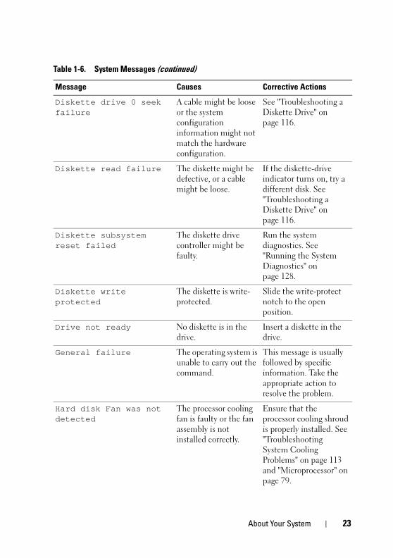
Diskette drive 0 seek failure
A cable might be loose or the system configuration information might not match the hardware configuration.
See "Troubleshooting a Diskette Drive" on page 116.
Diskette read failure The diskette might be defective, or a cable might be loose.
If the diskette-drive indicator turns on, try a different disk. See "Troubleshooting a Diskette Drive" on page 116.
Diskette subsystem reset failed
The diskette drive controller might be faulty.
Run the system diagnostics. See "Running the System Diagnostics" on page 128.
Diskette write protected
The diskette is write-protected.
Slide the write-protect notch to the open position.
Drive not ready No diskette is in the drive.
Insert a diskette in the drive.
General failure The operating system is unable to carry out the command.
This message is usually followed by specific information. Take the appropriate action to resolve the problem.
Hard disk Fan was not detected
The processor cooling fan is faulty or the fan assembly is not installed correctly.
Ensure that the processor cooling shroud is properly installed. See "Troubleshooting System Cooling Problems" on page 113 and "Microprocessor" on page 79.
Table 1-6. System Messages (continued)
Message Causes Corrective Actions
About Your System 23
book.book Page 24 Wednesday, April 15, 2009 8:47 PM
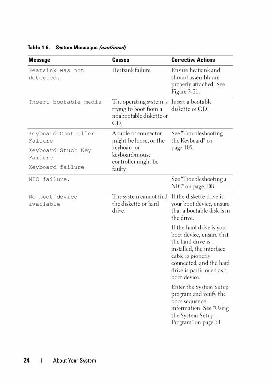
Heatsink was not detected.
Heatsink failure. Ensure heatsink and shroud assembly are properly attached. See Figure 3-21.
Insert bootable media The operating system is trying to boot from a nonbootable diskette or CD.
Insert a bootable diskette or CD.
Keyboard Controller Failure
Keyboard Stuck Key Failure
Keyboard failure
A cable or connector might be loose, or the keyboard or keyboard/mouse controller might be faulty.
See "Troubleshooting the Keyboard" on page 105.
NIC failure. See "Troubleshooting a NIC" on page 108.
No boot device available
The system cannot find the diskette or hard drive.
If the diskette drive is your boot device, ensure that a bootable disk is in the drive.
If the hard drive is your boot device, ensure that the hard drive is installed, the interface cable is properly connected, and the hard drive is partitioned as a boot device.
Enter the System Setup program and verify the boot sequence information. See "Using the System Setup Program" on page 31.
Table 1-6. System Messages (continued)
Message Causes Corrective Actions
24 About Your System
book.book Page 25 Wednesday, April 15, 2009 8:47 PM
No timer tick interrupt A chip on the system board might be malfunctioning.
Run the system diagnostics. See "Running the System Diagnostics" on page 127.
Non-system disk or disk error
The diskette in the diskette drive or your hard drive does not have a bootable operating system installed on it.
Replace the diskette with one that has a bootable operating system or remove the diskette, and then restart the system.
If the problem persists, see "Troubleshooting a Diskette Drive" on page 116 or "Troubleshooting a Hard Drive" on page 120.
If the problem persists, see "Getting Help" on page 137.
Not a boot diskette The operating system is trying to boot from a diskette that does not have a bootable operating system installed on it.
Insert a diskette that has a bootable operating system.
Not enough memory or resources. Close some programs and try again.
You have too many programs open.
Close all windows and open the program that you want to use. In some cases, you might have to restart your system to restore system resources. If so, try opening the program that you want to use first
Table 1-6. System Messages (continued)
Message Causes Corrective Actions
About Your System 25
book.book Page 26 Wednesday, April 15, 2009 8:47 PM
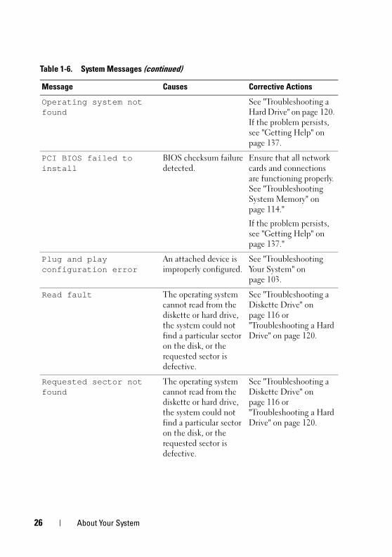
Operating system not found
See "Troubleshooting a Hard Drive" on page 120. If the problem persists, see "Getting Help" on page 137.
PCI BIOS failed to install
BIOS checksum failure detected.
Ensure that all network cards and connections are functioning properly. See "Troubleshooting System Memory" on page 114."
If the problem persists, see "Getting Help" on page 137."
Plug and play configuration error
An attached device is improperly configured.
See "Troubleshooting Your System" on page 103.
Read fault The operating system cannot read from the diskette or hard drive, the system could not find a particular sector on the disk, or the requested sector is defective.
See "Troubleshooting a Diskette Drive" on page 116 or "Troubleshooting a Hard Drive" on page 120.
Requested sector not found
The operating system cannot read from the diskette or hard drive, the system could not find a particular sector on the disk, or the requested sector is defective.
See "Troubleshooting a Diskette Drive" on page 116 or "Troubleshooting a Hard Drive" on page 120.
Table 1-6. System Messages (continued)
Message Causes Corrective Actions
26 About Your System
book.book Page 27 Wednesday, April 15, 2009 8:47 PM
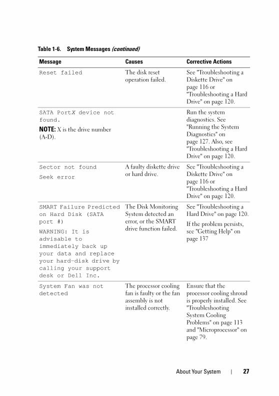
Reset failed The disk reset operation failed.
See "Troubleshooting a Diskette Drive" on page 116 or "Troubleshooting a Hard Drive" on page 120.
SATA PortX device not found.
NOTE: X is the drive number (A-D).
Run the system diagnostics. See "Running the System Diagnostics" on page 127. Also, see "Troubleshooting a Hard Drive" on page 120.
Sector not found
Seek error
A faulty diskette drive or hard drive.
See "Troubleshooting a Diskette Drive" on page 116 or "Troubleshooting a Hard Drive" on page 120.
SMART Failure Predicted on Hard Disk (SATA port #)
WARNING: It is advisable to immediately back up your data and replace your hard-disk drive by calling your support desk or Dell Inc.
The Disk Monitoring System detected an error, or the SMART drive function failed.
See "Troubleshooting a Hard Drive" on page 120.
If the problem persists, see "Getting Help" on page 137
System Fan was not detected
The processor cooling fan is faulty or the fan assembly is not installed correctly.
Ensure that the processor cooling shroud is properly installed. See "Troubleshooting System Cooling Problems" on page 113 and "Microprocessor" on page 79.
Table 1-6. System Messages (continued)
Message Causes Corrective Actions
About Your System 27
book.book Page 28 Wednesday, April 15, 2009 8:47 PM
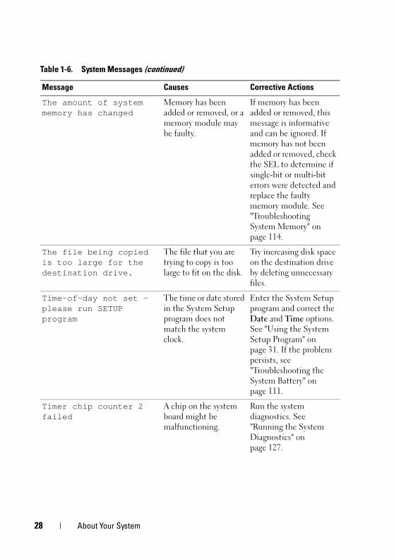
The amount of system memory has changed
Memory has been added or removed, or a memory module may be faulty.
If memory has been added or removed, this message is informative and can be ignored. If memory has not been added or removed, check the SEL to determine if single-bit or multi-bit errors were detected and replace the faulty memory module. See "Troubleshooting System Memory" on page 114.
The file being copied is too large for the destination drive.
The file that you are trying to copy is too large to fit on the disk.
Try increasing disk space on the destination drive by deleting unnecessary files.
Time-of-day not set — please run SETUP program
The time or date stored in the System Setup program does not match the system clock.
Enter the System Setup program and correct the Date and Time options. See "Using the System Setup Program" on page 31. If the problem persists, see "Troubleshooting the System Battery" on page 111.
Timer chip counter 2 failed
A chip on the system board might be malfunctioning.
Run the system diagnostics. See "Running the System Diagnostics" on page 127.
Table 1-6. System Messages (continued)
Message Causes Corrective Actions
28 About Your System
book.book Page 29 Wednesday, April 15, 2009 8:47 PM
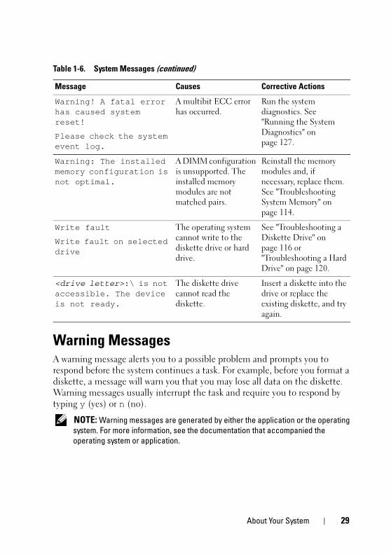
Warning MessagesA warning message alerts you to a possible problem and prompts you to respond before the system continues a task. For example, before you format a diskette, a message will warn you that you may lose all data on the diskette. Warning messages usually interrupt the task and require you to respond by typing y (yes) or n (no).
NOTE: Warning messages are generated by either the application or the operating
system. For more information, see the documentation that accompanied the
operating system or application.
Warning! A fatal error has caused system reset!
Please check the system event log.
A multibit ECC error has occurred.
Run the system diagnostics. See "Running the System Diagnostics" on page 127.
Warning: The installed memory configuration is not optimal.
A DIMM configuration is unsupported. The installed memory modules are not matched pairs.
Reinstall the memory modules and, if necessary, replace them. See "Troubleshooting System Memory" on page 114.
Write fault
Write fault on selected drive
The operating system cannot write to the diskette drive or hard drive.
See "Troubleshooting a Diskette Drive" on page 116 or "Troubleshooting a Hard Drive" on page 120.
<drive letter>:\ is not accessible. The device is not ready.
The diskette drive cannot read the diskette.
Insert a diskette into the drive or replace the existing diskette, and try again.
Table 1-6. System Messages (continued)
Message Causes Corrective Actions
About Your System 29
book.book Page 30 Wednesday, April 15, 2009 8:47 PM
Diagnostics MessagesWhen you run system diagnostics, an error message may result. Diagnostic error messages are not covered in this section. Record the message on a copy of the Diagnostics Checklist in "Getting Help" on page 137, and then follow the instructions in that section for obtaining technical assistance.
Alert MessagesSystems management software generates alert messages for your system. Alert messages include information, status, warning, and failure messages for drive, temperature, fan, and power conditions. For more information, see the systems management software documentation.
30 About Your System
book.book Page 31 Wednesday, April 15, 2009 8:47 PM
Using the System Setup ProgramAfter you set up your system, run the System Setup program to familiarize yourself with your system configuration and optional settings. Record the information for future reference.
You can use the System Setup program to:
• Change the system configuration stored in NVRAM after you add, change, or remove hardware
• Set or change user-selectable options—for example, the time or date
• Enable or disable integrated devices
• Correct discrepancies between the installed hardware and configuration settings
Entering the System Setup Program1 Turn on or restart your system.
2 Press <F2> immediately after you see the following message:
Please wait
If your operating system begins to load before you press <F2>, allow the system to finish booting, and then restart your system and try again.
NOTE: To ensure an orderly system shutdown, see the documentation that
accompanied your operating system.
Responding to Error Messages
You can enter the System Setup program by responding to certain error messages. If an error message appears while the system is booting, make a note of the message. Before entering the System Setup program, see "System Messages" on page 20 for an explanation of the message and suggestions for correcting errors.
NOTE: After installing a memory upgrade, it is normal for your system to send a
message the first time you start your system.
Using the System Setup Program 31
book.book Page 32 Wednesday, April 15, 2009 8:47 PM
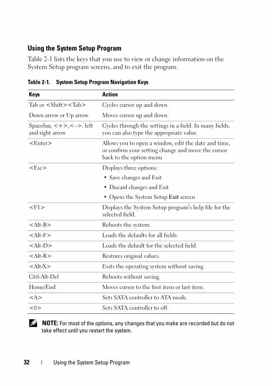
Using the System Setup Program
Table 2-1 lists the keys that you use to view or change information on the System Setup program screens, and to exit the program.
NOTE: For most of the options, any changes that you make are recorded but do not
take effect until you restart the system.
Table 2-1. System Setup Program Navigation Keys
Keys Action
Tab or <Shift><Tab> Cycles cursor up and down.
Down arrow or Up arrow Moves cursor up and down.
Spacebar, <+>,<–>, left and right arrow
Cycles through the settings in a field. In many fields, you can also type the appropriate value.
<Enter> Allows you to open a window, edit the date and time, or confirm your setting change and move the cursor back to the option menu
<Esc> Displays three options:
• Save changes and Exit
• Discard changes and Exit
• Opens the System Setup Exit screen
<F1> Displays the System Setup program's help file for the selected field.
<Alt-B> Reboots the system.
<Alt-F> Loads the defaults for all fields.
<Alt-D> Loads the default for the selected field.
<Alt-R> Restores original values.
<Alt-X> Exits the operating system without saving.
Ctrl-Alt-Del Reboots without saving.
Home/End Moves cursor to the first item or last item.
<A> Sets SATA controller to ATA mode.
<0> Sets SATA controller to off.
32 Using the System Setup Program
book.book Page 33 Wednesday, April 15, 2009 8:47 PM
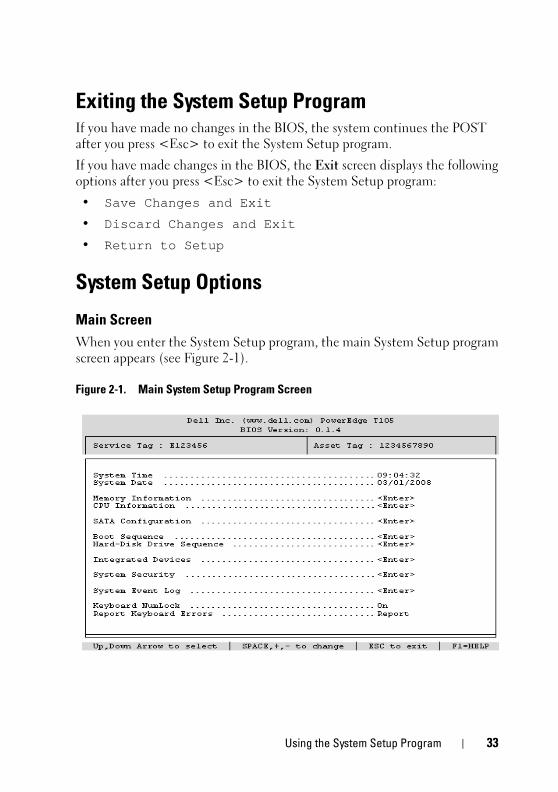
Exiting the System Setup ProgramIf you have made no changes in the BIOS, the system continues the POST after you press <Esc> to exit the System Setup program.
If you have made changes in the BIOS, the Exit screen displays the following options after you press <Esc> to exit the System Setup program:
• Save Changes and Exit
• Discard Changes and Exit
• Return to Setup
System Setup Options
Main Screen
When you enter the System Setup program, the main System Setup program screen appears (see Figure 2-1).
Figure 2-1. Main System Setup Program Screen
Using the System Setup Program 33
book.book Page 34 Wednesday, April 15, 2009 8:47 PM
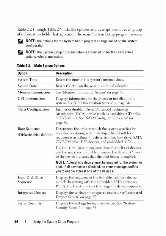
Table 2-2 through Table 2-9 lists the options and descriptions for each group of information fields that appear on the main System Setup program screen.
NOTE: The options for the System Setup program change based on the system
configuration.
NOTE: The System Setup program defaults are listed under their respective
options, where applicable.
Table 2-2. Main System Options
Option Description
System Time Resets the time on the system’s internal clock.
System Date Resets the date on the system’s internal calendar.
Memory Information See "Memory Information Screen" on page 35.
CPU Information Displays information for the processor installed in the system. See "CPU Information Screen" on page 36.
SATA Configuration Enables or disables a Serial Advanced Technology Attachment (SATA) device (such as hard drive, CD drive, or DVD drive). See "SATA Configuration Screen" on page 36.
Boot Sequence
(Diskette drive default)
Determines the order in which the system searches for boot devices during system startup. The default boot sequence is as follows: the diskette drive, hard drive, SATA CD-ROM drive, USB devices, and embedded NICs.
Use the + or – keys to navigate through the list of devices and the space key to disable or enable the device. A V next to the device indicates that the boot device is enabled.
NOTE: At least one device must be enabled for the system to
boot. If all devices are disabled, an error message notifies
you to enable at least one of the devices.
Hard-Disk Drive Sequence
Displays the sequence of the bootable hard-disk device models, beginning with the embedded SATA device on Port A. Use the + or – keys to change the device sequence.
Integrated Devices Displays the settings for integrated devices. See "Integrated Devices Screen" on page 37.
System Security Displays the settings for security devices. See "System Security Screen" on page 38.
34 Using the System Setup Program
book.book Page 35 Wednesday, April 15, 2009 8:47 PM
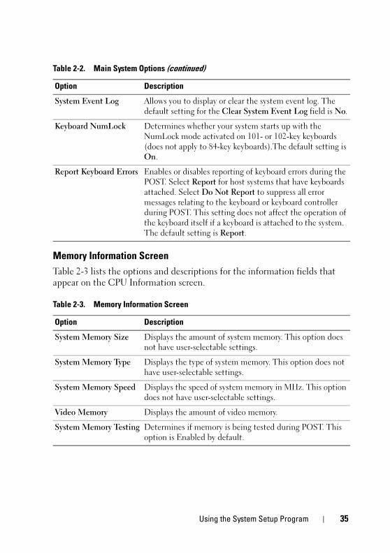
Memory Information Screen
Table 2-3 lists the options and descriptions for the information fields that appear on the CPU Information screen.
System Event Log Allows you to display or clear the system event log. The default setting for the Clear System Event Log field is No.
Keyboard NumLock Determines whether your system starts up with the NumLock mode activated on 101- or 102-key keyboards (does not apply to 84-key keyboards).The default setting is On.
Report Keyboard Errors Enables or disables reporting of keyboard errors during the POST. Select Report for host systems that have keyboards attached. Select Do Not Report to suppress all error messages relating to the keyboard or keyboard controller during POST. This setting does not affect the operation of the keyboard itself if a keyboard is attached to the system. The default setting is Report.
Table 2-3. Memory Information Screen
Option Description
System Memory Size Displays the amount of system memory. This option does not have user-selectable settings.
System Memory Type Displays the type of system memory. This option does not have user-selectable settings.
System Memory Speed Displays the speed of system memory in MHz. This option does not have user-selectable settings.
Video Memory Displays the amount of video memory.
System Memory Testing Determines if memory is being tested during POST. This option is Enabled by default.
Table 2-2. Main System Options (continued)
Option Description
Using the System Setup Program 35
book.book Page 36 Wednesday, April 15, 2009 8:47 PM
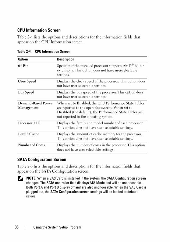
CPU Information Screen
Table 2-4 lists the options and descriptions for the information fields that appear on the CPU Information screen.
SATA Configuration Screen
Table 2-5 lists the options and descriptions for the information fields that appear on the SATA Configuration screen.
NOTE: When a SAS Card is installed in the system, the SATA Configuration screen
changes. The SATA controller field displays ATA Mode and will be unchoosable.
Both Port A and Port B display off and are also unchoosable. When the SAS Card is
plugged out, the SATA Configuration screen settings will be loaded to default
values.
Table 2-4. CPU Information Screen
Option Description
64-Bit Specifies if the installed processor supports AMD® 64-bit extensions. This option does not have user-selectable settings.
Core Speed Displays the clock speed of the processor. This option does not have user-selectable settings.
Bus Speed Displays the bus speed of the processor. This option does not have user-selectable settings.
Demand-Based Power Management
When set to Enabled, the CPU Performance State Tables are reported to the operating system. When set to Disabled (the default), the Performance State Tables are not reported to the operating system.
Processor 1 ID Displays the family and model number of each processor. This option does not have user-selectable settings.
Level2 Cache Displays the amount of cache memory for the processor. This option does not have user-selectable settings.
Number of Cores Displays the number of cores in the processor. This option does not have user-selectable settings.
36 Using the System Setup Program
book.book Page 37 Wednesday, April 15, 2009 8:47 PM
Integrated Devices Screen
Table 2-6 lists the options and descriptions for the information fields that appear on the Integrated Devices screen.
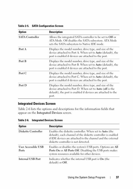
Table 2-5. SATA Configuration Screen
Option Description
SATA Controller Allows the integrated SATA controller to be set to Off or ATA Mode. Off disables the SATA subsystem. ATA Mode sets the SATA subsystem to Native IDE mode.
Port A Displays the model number, drive type, and size of the device attached to Port A. When set to Auto (default), the port is enabled if devices are attached to the port.
Port B Displays the model number, drive type, and size of the device attached to Port B. When set to Auto (default), the port is enabled if devices are attached to the port.
Port C Displays the model number, drive type, and size of the device attached to Port C. When set to Auto (default), the port is enabled if devices are attached to the port.
Port D Displays the model number, drive type, and size of the device attached to Port D. When set to Auto (off is the default), the port is enabled if devices are attached to the port.
Table 2-6. Integrated Devices Screen
Option Description
Diskette Controller Enables the diskette controller. When set to Auto (the default), each channel of the diskette controller is enabled if IDE devices are attached to the channel and the external diskette controller is not detected.
User Accessible USB Ports
Enables or disables the system's USB ports. Options are All Ports On or All Ports Off. Disabling the USB ports makes system resources available for other devices.
Internal USB Port Indicates whether the internal USB port is On (the default) or Off.
Using the System Setup Program 37
book.book Page 38 Wednesday, April 15, 2009 8:47 PM
System Security Screen
Table 2-7 lists the options and descriptions for the information fields that appear on the System Security screen.
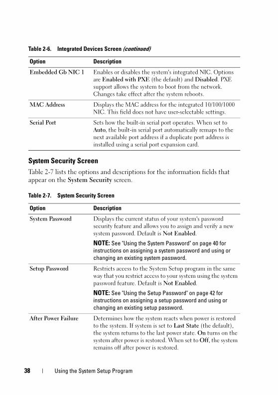
Embedded Gb NIC 1 Enables or disables the system's integrated NIC. Options are Enabled with PXE (the default) and Disabled. PXE support allows the system to boot from the network. Changes take effect after the system reboots.
MAC Address Displays the MAC address for the integrated 10/100/1000 NIC. This field does not have user-selectable settings.
Serial Port Sets how the built-in serial port operates. When set to Auto, the built-in serial port automatically remaps to the next available port address if a duplicate port address is installed using a serial port expansion card.
Table 2-7. System Security Screen
Option Description
System Password Displays the current status of your system's password security feature and allows you to assign and verify a new system password. Default is Not Enabled.
NOTE: See "Using the System Password" on page 40 for
instructions on assigning a system password and using or
changing an existing system password.
Setup Password Restricts access to the System Setup program in the same way that you restrict access to your system using the system password feature. Default is Not Enabled.
NOTE: See "Using the Setup Password" on page 42 for
instructions on assigning a setup password and using or
changing an existing setup password.
After Power Failure Determines how the system reacts when power is restored to the system. If system is set to Last State (the default), the system returns to the last power state. On turns on the system after power is restored. When set to Off, the system remains off after power is restored.
Table 2-6. Integrated Devices Screen (continued)
Option Description
38 Using the System Setup Program
book.book Page 39 Wednesday, April 15, 2009 8:47 PM
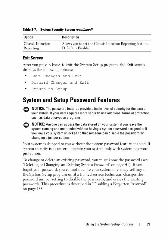
Exit Screen
After you press <Esc> to exit the System Setup program, the Exit screen displays the following options:
• Save Changes and Exit
• Discard Changes and Exit
• Return to Setup
System and Setup Password Features NOTICE: The password features provide a basic level of security for the data on
your system. If your data requires more security, use additional forms of protection,
such as data encryption programs.
NOTICE: Anyone can access the data stored on your system if you leave the
system running and unattended without having a system password assigned or if
you leave your system unlocked so that someone can disable the password by
changing a jumper setting.
Your system is shipped to you without the system password feature enabled. If system security is a concern, operate your system only with system password protection.
To change or delete an existing password, you must know the password (see "Deleting or Changing an Existing System Password" on page 41). If you forget your password, you cannot operate your system or change settings in the System Setup program until a trained service technician changes the password jumper setting to disable the passwords, and erases the existing passwords. This procedure is described in "Disabling a Forgotten Password" on page 135.
Chassis Intrusion Reporting
Allows you to set the Chassis Intrusion Reporting feature. Default is Enabled.
Table 2-7. System Security Screen (continued)
Option Description
Using the System Setup Program 39
book.book Page 40 Wednesday, April 15, 2009 8:47 PM
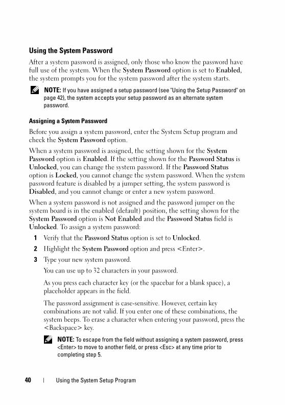
Using the System Password
After a system password is assigned, only those who know the password have full use of the system. When the System Password option is set to Enabled, the system prompts you for the system password after the system starts.
NOTE: If you have assigned a setup password (see "Using the Setup Password" on
page 42), the system accepts your setup password as an alternate system
password.
Assigning a System Password
Before you assign a system password, enter the System Setup program and check the System Password option.
When a system password is assigned, the setting shown for the System Password option is Enabled. If the setting shown for the Password Status is Unlocked, you can change the system password. If the Password Status option is Locked, you cannot change the system password. When the system password feature is disabled by a jumper setting, the system password is Disabled, and you cannot change or enter a new system password.
When a system password is not assigned and the password jumper on the system board is in the enabled (default) position, the setting shown for the System Password option is Not Enabled and the Password Status field is Unlocked. To assign a system password:
1 Verify that the Password Status option is set to Unlocked.
2 Highlight the System Password option and press <Enter>.
3 Type your new system password.
You can use up to 32 characters in your password.
As you press each character key (or the spacebar for a blank space), a placeholder appears in the field.
The password assignment is case-sensitive. However, certain key combinations are not valid. If you enter one of these combinations, the system beeps. To erase a character when entering your password, press the <Backspace> key.
NOTE: To escape from the field without assigning a system password, press
<Enter> to move to another field, or press <Esc> at any time prior to
completing step 5.
40 Using the System Setup Program
book.book Page 41 Wednesday, April 15, 2009 8:47 PM
4 Press <Enter>.
5 To confirm your password, type it a second time and press <Enter>.
6 Press <Enter> again to continue.
The setting shown for the System Password changes to Enabled.
7 Save and exit the System Setup program and begin using your system.
NOTE: Password protection does not take effect until you reboot the system.
Using Your System Password to Secure Your System
NOTE: If you have assigned a setup password (see "Using the Setup Password" on
page 42), the system accepts your setup password as an alternate system
password.
When the Password Status option is set to Unlocked, you have the option to leave the password security enabled or to disable the password security.
To leave the password security enabled:
1 Turn on or reboot your system by pressing <Ctrl><Alt><Del>.
2 Type your password and press <Enter>.
When you turn on or reboot your system, type your password and press <Enter> at the prompt.
After you type the correct system password and press <Enter>, your system operates as usual.
If an incorrect system password is entered, the system displays a message and prompts you to re-enter your password. You have three attempts to enter the correct password. After the third unsuccessful attempt, the system displays an error message stating that the system has halted.
NOTE: You can use the Password Status option in conjunction with the System
Password and Setup Password options to further protect your system from
unauthorized changes.
Deleting or Changing an Existing System Password
1 Enter the System Setup program by pressing <F2> during POST.
2 Select the System Security screen field to verify that the Password Status option is set to Unlocked.
Using the System Setup Program 41
book.book Page 42 Wednesday, April 15, 2009 8:47 PM
3 When prompted, type the valid system password and press <Enter>. Press <Enter> in the new password field and press <Enter> in the confirm new password field.
4 Confirm that Not Enabled is displayed for the System Password option.
If Not Enabled is displayed for the System Password option, the system password has been deleted. If Enabled is displayed for the System Password option, press the <Alt><b> key combination to restart the system, and then repeat steps 2 through 5.
Using the Setup Password
Assigning a Setup Password
You can assign (or change) a setup password only when the Setup Password option is set to Not Enabled. To assign an setup password, highlight the Setup Password option and press the <Enter> key. The system prompts you to enter and verify the password. If a character is illegal for password use, the system beeps.
NOTE: The setup password can be the same as the system password. If the two
passwords are different, the setup password can be used as an alternate system
password. However, the system password cannot be used in place of the setup
password.
You can use up to 32 characters in your password.
As you press each character key (or the spacebar for a blank space), a placeholder appears in the field.
The password assignment is case-sensitive. However, certain key combinations are not valid. If you enter one of these combinations, the system beeps. To erase a character when entering your password, press the <Backspace> key.
After you verify the password, the Setup Password setting changes to Enabled. The next time you enter the System Setup program, the system prompts you for the setup password.
A change to the Setup Password option becomes effective immediately (restarting the system is not required).
42 Using the System Setup Program
book.book Page 43 Wednesday, April 15, 2009 8:47 PM
Operating With a Setup Password Set
If Setup Password is Enabled, you must enter the correct setup password before you can modify the System Setup options. When you start the System Setup program, the program prompts you to enter a password.
If you do not enter the correct password in three attempts, the system displays an error message stating that the system has halted.
Deleting or Changing an Existing Setup Password
1 Enter the System Setup program and select the System Security option.
2 Highlight the Setup Password option, press <Enter> to access the setup password window. Type the correct password and press <Enter>, then press <Enter> twice to clear the existing setup password.
The setting changes to Not Enabled.
3 If you want to assign a new setup password, perform the steps in "Assigning a Setup Password" on page 42.
Disabling a Forgotten Password
See "Disabling a Forgotten Password" on page 135.
Using the System Setup Program 43

book.book Page 44 Wednesday, April 15, 2009 8:47 PM
44 Using the System Setup Program
book.book Page 45 Wednesday, April 15, 2009 8:47 PM
Installing System ComponentsThis section describes how to install the following system components:
• Front drive bezel
• Diskette drive
• Optical and tape drives
• Hard drives
• Expansion cards
• SAS controller card
• Memory
• Microprocessor
• Cooling fans
• System battery
• Power supply
• Chassis intrusion switch
• Bezel
• I/O panel
• System board
Recommended ToolsYou may need the following items to perform the procedures in this section:
• #2 Phillips screwdriver
• Wrist grounding strap
Installing System Components 45
book.book Page 46 Wednesday, April 15, 2009 8:47 PM
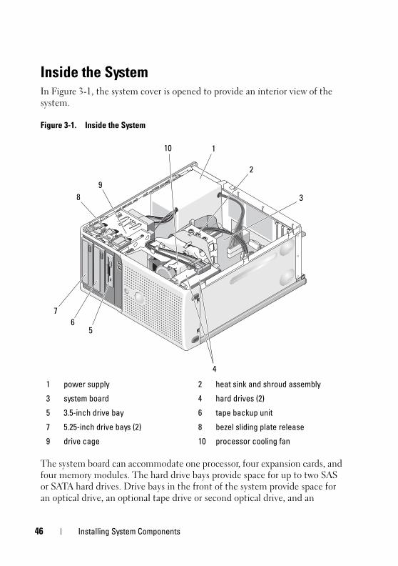
Inside the SystemIn Figure 3-1, the system cover is opened to provide an interior view of the system.
Figure 3-1. Inside the System
The system board can accommodate one processor, four expansion cards, and four memory modules. The hard drive bays provide space for up to two SAS or SATA hard drives. Drive bays in the front of the system provide space for an optical drive, an optional tape drive or second optical drive, and an
1 power supply 2 heat sink and shroud assembly
3 system board 4 hard drives (2)
5 3.5-inch drive bay 6 tape backup unit
7 5.25-inch drive bays (2) 8 bezel sliding plate release
9 drive cage 10 processor cooling fan
3
2
1
7
5
10
4
8
9
6
46 Installing System Components
book.book Page 47 Wednesday, April 15, 2009 8:47 PM
optional diskette drive. A controller expansion card is required for SAS hard drives. Power is supplied to the system board and internal peripherals through a single nonredundant power supply.
Opening the System CAUTION: Only trained service technicians are authorized to remove the system
cover and access any of the components inside the system. Before performing any
procedure, see your Product Information Guide for complete information about
safety precautions, working inside the computer and protecting against
electrostatic discharge.
1 Turn off the system and attached peripherals, and disconnect the system from the electrical outlet.
2 Press the power button to ground the system board.
3 Lay the system on its side as shown in Figure 3-2.
4 Open the system by sliding the cover release tab toward the rear of the system and lifting the cover off. See Figure 3-2.
Closing the System1 Ensure that all internal cables are connected and folded out of the way.
2 Ensure that no tools or extra parts are left inside the system.
3 Reinstall the system cover:
a Insert the bottom edge of the cover into the bottom of the system chassis. See Figure 3-2.
b Press down on the cover until the cover release tab snaps into place.
4 Reconnect the system to the electrical outlet, and turn on the system and attached peripherals.
After you open and close the cover, the chassis intrusion detector, if enabled, causes the following message to appear on the screen at the next system start-up:
Alert! Cover was previously opened.
Installing System Components 47
book.book Page 48 Wednesday, April 15, 2009 8:47 PM
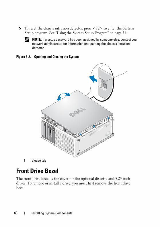
5 To reset the chassis intrusion detector, press <F2> to enter the System Setup program. See "Using the System Setup Program" on page 31.
NOTE: If a setup password has been assigned by someone else, contact your
network administrator for information on resetting the chassis intrusion
detector.
Figure 3-2. Opening and Closing the System
Front Drive BezelThe front drive bezel is the cover for the optional diskette and 5.25-inch drives. To remove or install a drive, you must first remove the front drive bezel.
1 release tab
1
48 Installing System Components
book.book Page 49 Wednesday, April 15, 2009 8:47 PM
CAUTION: Only trained service technicians are authorized to remove the system
cover and access any of the components inside the system. Before performing any
procedure, see your Product Information Guide for complete information about
safety precautions, working inside the computer and protecting against
electrostatic discharge.
Removing the Front Drive Bezel
1 Turn off the system and attached peripherals, and disconnect the system from the electrical outlet.
2 Open the system. See "Opening the System" on page 47.
NOTE: The sliding plate secures and releases the front drive bezel and helps
to secure the drives.
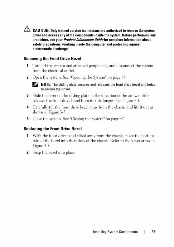
3 Slide the lever on the sliding plate in the direction of the arrow until it releases the front drive bezel from its side hinges. See Figure 3-3.
4 Carefully tilt the front drive bezel away from the chassis and lift it out as shown in Figure 3-3.
5 Close the system. See "Closing the System" on page 47.
Replacing the Front Drive Bezel
1 With the front drive bezel tilted away from the chassis, place the bottom tabs of the bezel into their slots of the chassis. Refer to the lower arrow in Figure 3-3.
2 Snap the bezel into place.
Installing System Components 49
book.book Page 50 Wednesday, April 15, 2009 8:47 PM
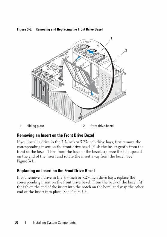
Figure 3-3. Removing and Replacing the Front Drive Bezel
Removing an Insert on the Front Drive Bezel
If you install a drive in the 3.5-inch or 5.25-inch drive bays, first remove the corresponding insert on the front drive bezel. Push the insert gently from the front of the bezel. Then from the back of the bezel, squeeze the tab upward on the end of the insert and rotate the insert away from the bezel. See Figure 3-4.
Replacing an Insert on the Front Drive Bezel
If you remove a drive in the 3.5-inch or 5.25-inch drive bays, replace the corresponding insert on the front drive bezel. From the back of the bezel, fit the tab on the end of the insert into the notch on the bezel and snap the other end of the insert into place. See Figure 3-4.
1 sliding plate 2 front drive bezel
2
1
50 Installing System Components
book.book Page 51 Wednesday, April 15, 2009 8:47 PM
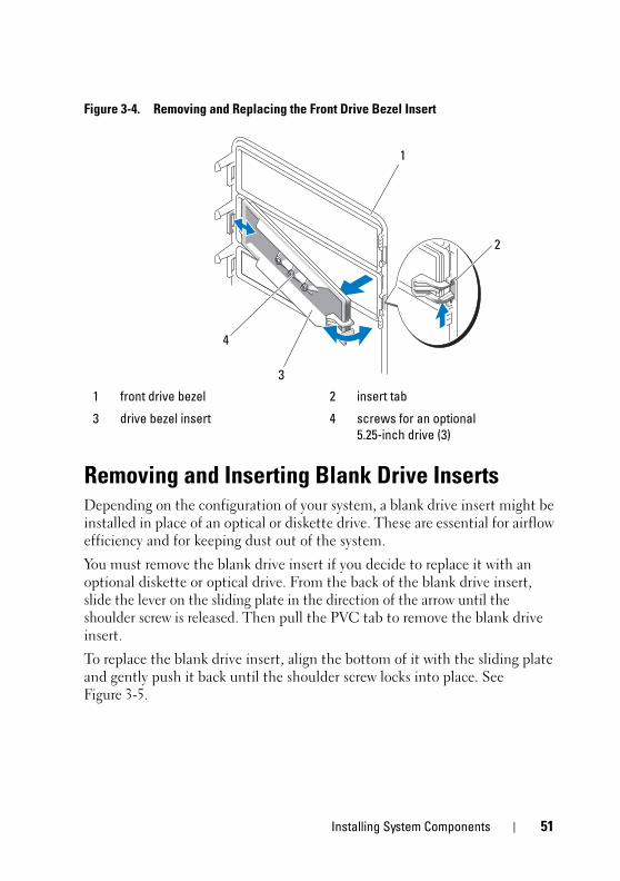
Figure 3-4. Removing and Replacing the Front Drive Bezel Insert
Removing and Inserting Blank Drive InsertsDepending on the configuration of your system, a blank drive insert might be installed in place of an optical or diskette drive. These are essential for airflow efficiency and for keeping dust out of the system.
You must remove the blank drive insert if you decide to replace it with an optional diskette or optical drive. From the back of the blank drive insert, slide the lever on the sliding plate in the direction of the arrow until the shoulder screw is released. Then pull the PVC tab to remove the blank drive insert.
To replace the blank drive insert, align the bottom of it with the sliding plate and gently push it back until the shoulder screw locks into place. See Figure 3-5.
1 front drive bezel 2 insert tab
3 drive bezel insert 4 screws for an optional
5.25-inch drive (3)
1
3
2
4
Installing System Components 51
book.book Page 52 Wednesday, April 15, 2009 8:47 PM
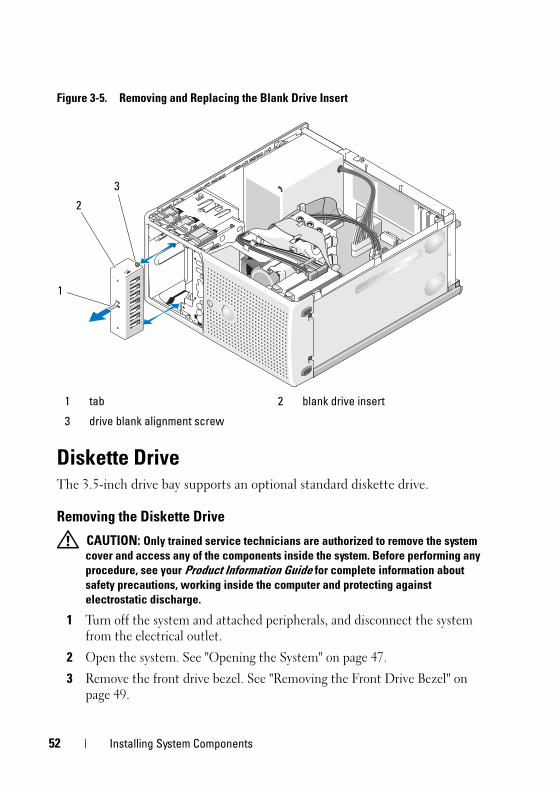
Figure 3-5. Removing and Replacing the Blank Drive Insert
Diskette DriveThe 3.5-inch drive bay supports an optional standard diskette drive.
Removing the Diskette Drive
CAUTION: Only trained service technicians are authorized to remove the system
cover and access any of the components inside the system. Before performing any
procedure, see your Product Information Guide for complete information about
safety precautions, working inside the computer and protecting against
electrostatic discharge.
1 Turn off the system and attached peripherals, and disconnect the system from the electrical outlet.
2 Open the system. See "Opening the System" on page 47.
3 Remove the front drive bezel. See "Removing the Front Drive Bezel" on page 49.
1 tab 2 blank drive insert
3 drive blank alignment screw
2
3
1
52 Installing System Components
book.book Page 53 Wednesday, April 15, 2009 8:47 PM
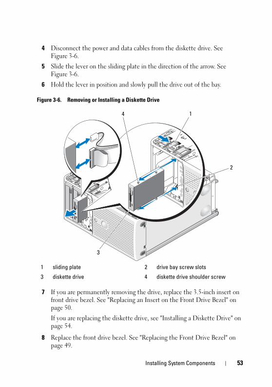
4 Disconnect the power and data cables from the diskette drive. See Figure 3-6.
5 Slide the lever on the sliding plate in the direction of the arrow. See Figure 3-6.
6 Hold the lever in position and slowly pull the drive out of the bay.
Figure 3-6. Removing or Installing a Diskette Drive
7 If you are permanently removing the drive, replace the 3.5-inch insert on front drive bezel. See "Replacing an Insert on the Front Drive Bezel" on page 50.
If you are replacing the diskette drive, see "Installing a Diskette Drive" on page 54.
8 Replace the front drive bezel. See "Replacing the Front Drive Bezel" on page 49.
1 sliding plate 2 drive bay screw slots
3 diskette drive 4 diskette drive shoulder screw
1
2
3
4
Installing System Components 53
book.book Page 54 Wednesday, April 15, 2009 8:47 PM
9 Close the system. See "Closing the System" on page 47.
10 Reconnect the system to the electrical outlet, and turn on the system and attached peripherals.
Installing a Diskette Drive
CAUTION: Only trained service technicians are authorized to remove the system
cover and access any of the components inside the system. Before performing any
procedure, see your Product Information Guide for complete information about
safety precautions, working inside the computer and protecting against
electrostatic discharge.
1 Turn off the system and attached peripherals, and disconnect the system from the electrical outlet.
2 Open the system. See "Opening the System" on page 47.
3 Unpack the replacement diskette drive, and prepare it for installation.
4 Check the documentation for the drive to verify that it is configured for your system.
5 Remove the front drive bezel. See "Removing the Front Drive Bezel" on page 49.
6 Remove the 3.5-inch insert on the front drive bezel. See "Removing an Insert on the Front Drive Bezel" on page 50.
7 Remove the four shoulder screws from the back of the insert. See Figure 3-4; the 3.5-inch insert holds four screws.
8 Attach the four screws to the diskette drive as shown in Figure 3-7.
54 Installing System Components
book.book Page 55 Wednesday, April 15, 2009 8:47 PM
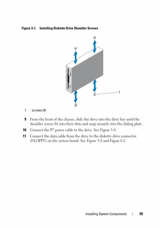
Figure 3-7. Installing Diskette Drive Shoulder Screws
9 From the front of the chassis, slide the drive into the drive bay until the shoulder screws fit into their slots and snap securely into the sliding plate.
10 Connect the P7 power cable to the drive. See Figure 3-8.
11 Connect the data cable from the drive to the diskette drive connector (FLOPPY) on the system board. See Figure 3-8 and Figure 6-2.
1 screws (4)
1
Installing System Components 55
book.book Page 56 Wednesday, April 15, 2009 8:47 PM
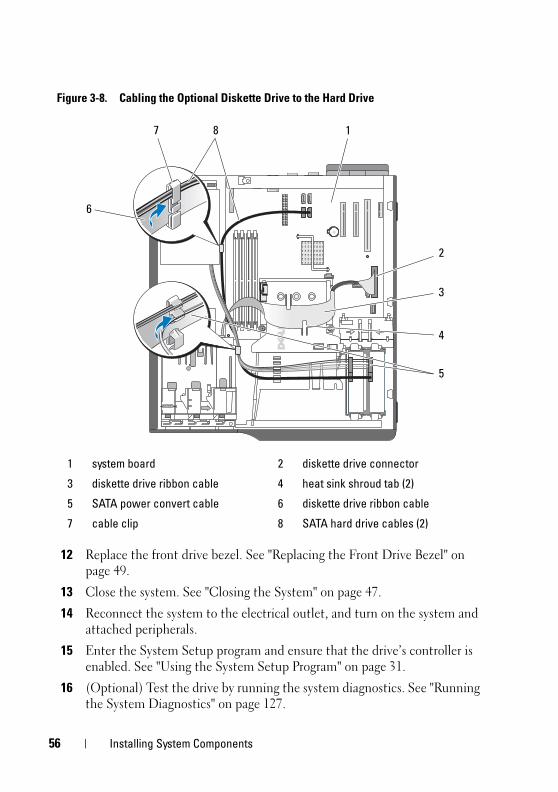
Figure 3-8. Cabling the Optional Diskette Drive to the Hard Drive
12 Replace the front drive bezel. See "Replacing the Front Drive Bezel" on page 49.
13 Close the system. See "Closing the System" on page 47.
14 Reconnect the system to the electrical outlet, and turn on the system and attached peripherals.
15 Enter the System Setup program and ensure that the drive’s controller is enabled. See "Using the System Setup Program" on page 31.
16 (Optional) Test the drive by running the system diagnostics. See "Running the System Diagnostics" on page 127.
1 system board 2 diskette drive connector
3 diskette drive ribbon cable 4 heat sink shroud tab (2)
5 SATA power convert cable 6 diskette drive ribbon cable
7 cable clip 8 SATA hard drive cables (2)
2
8 1
3
4
5
7
6
56 Installing System Components
book.book Page 57 Wednesday, April 15, 2009 8:47 PM
Optical and Tape DrivesIn the upper 5.25-inch drive bay, you can install only an optical drive. In the lower 5.25-inch drive bay, you can install either an optical or a tape backup unit.
Removing an Optical or Tape Drive
CAUTION: Only trained service technicians are authorized to remove the system
cover and access any of the components inside the system. Before performing any
procedure, see your Product Information Guide for complete information about
safety precautions, working inside the computer and protecting against
electrostatic discharge.
1 Turn off the system and attached peripherals, and disconnect the system from the electrical outlet.
2 Open the system. See "Opening the System" on page 47.
3 Remove the front drive bezel. See "Removing the Front Drive Bezel" on page 49.
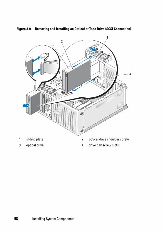
4 Disconnect the power and data cables from the back of the drive. See Figure 3-9 for disconnecting SCSI connections and Figure 3-10 for disconnecting SATA connections.
5 Slide the lever on the sliding plate in the direction of the arrow to release the shoulder screw.
6 Slide the drive out to remove it from the drive bay.
Installing System Components 57
book.book Page 58 Wednesday, April 15, 2009 8:47 PM
Figure 3-9. Removing and Installing an Optical or Tape Drive (SCSI Connection)
1 sliding plate 2 optical drive shoulder screw
3 optical drive 4 drive bay screw slots
2
3
1
4
58 Installing System Components
book.book Page 59 Wednesday, April 15, 2009 8:47 PM
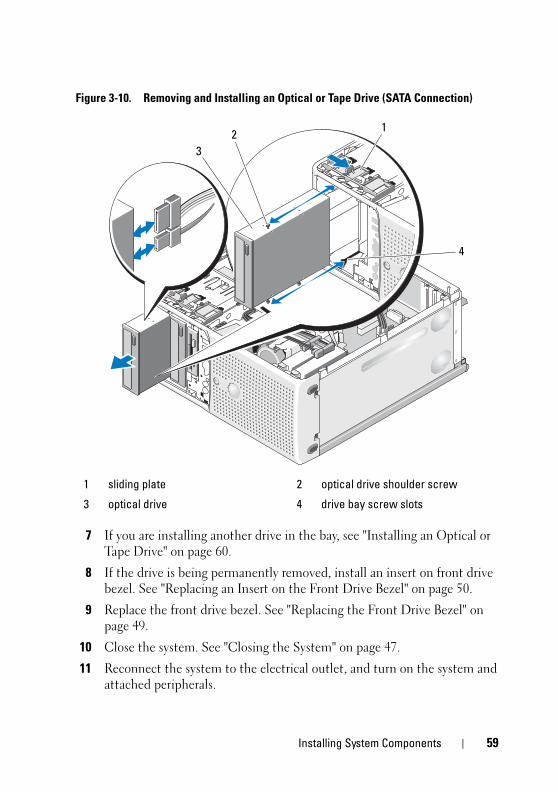
Figure 3-10. Removing and Installing an Optical or Tape Drive (SATA Connection)
7 If you are installing another drive in the bay, see "Installing an Optical or Tape Drive" on page 60.
8 If the drive is being permanently removed, install an insert on front drive bezel. See "Replacing an Insert on the Front Drive Bezel" on page 50.
9 Replace the front drive bezel. See "Replacing the Front Drive Bezel" on page 49.
10 Close the system. See "Closing the System" on page 47.
11 Reconnect the system to the electrical outlet, and turn on the system and attached peripherals.
1 sliding plate 2 optical drive shoulder screw
3 optical drive 4 drive bay screw slots
2
3
1
4
Installing System Components 59
book.book Page 60 Wednesday, April 15, 2009 8:47 PM
Installing an Optical or Tape Drive
CAUTION: Only trained service technicians are authorized to remove the system
cover and access any of the components inside the system. Before performing any
procedure, see your Product Information Guide for complete information about
safety precautions, working inside the computer and protecting against
electrostatic discharge.
1 Unpack the drive and prepare it for installation. For instructions, see the documentation that accompanied the drive.
If you are installing a SCSI tape drive, you must have a SCSI controller card installed (see "Installing an Expansion Card" on page 72) and configure the tape drive according to the documentation that came with the tape drive, based on the following guidelines:
a Each device attached to a SCSI host adapter must have a unique SCSI ID number (narrow SCSI devices use IDs 0 to 7; wide SCSI devices use IDs from 0 to 15). Set the drive’s SCSI ID to avoid conflicts with other devices on the SCSI bus. For the default SCSI ID setting, see the documentation provided with the drive.
NOTE: There is no requirement that SCSI ID numbers be assigned
sequentially or that devices be attached to the cable in order by ID number.
b SCSI logic requires that the two devices at opposite ends of a SCSI chain be terminated and that all devices in between be unterminated. Therefore, you enable the tape drive’s termination if it is the last device in a chain of devices (or sole device) connected to the SCSI controller.
2 Turn off the system, including any attached peripherals, and disconnect the system from the electrical outlet.
3 Open the system. See "Opening the System" on page 47.
4 Remove the front drive bezel. See "Removing the Front Drive Bezel" on page 49.
5 If another drive is installed, remove it (see "Removing an Optical or Tape Drive" on page 57) and remove the three shoulder screws to attach to the new drive (see Figure 3-11).
6 If the drive bay is empty, remove the insert on the front drive bezel. See "Removing an Insert on the Front Drive Bezel" on page 50.
60 Installing System Components
book.book Page 61 Wednesday, April 15, 2009 8:47 PM
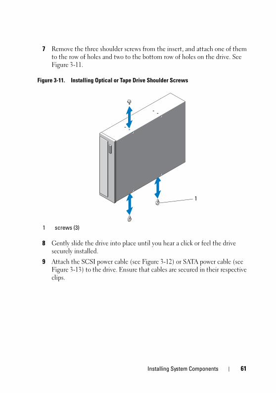
7 Remove the three shoulder screws from the insert, and attach one of them to the row of holes and two to the bottom row of holes on the drive. See Figure 3-11.
Figure 3-11. Installing Optical or Tape Drive Shoulder Screws
8 Gently slide the drive into place until you hear a click or feel the drive securely installed.
9 Attach the SCSI power cable (see Figure 3-12) or SATA power cable (see Figure 3-13) to the drive. Ensure that cables are secured in their respective clips.
1 screws (3)
1
Installing System Components 61
book.book Page 62 Wednesday, April 15, 2009 8:47 PM
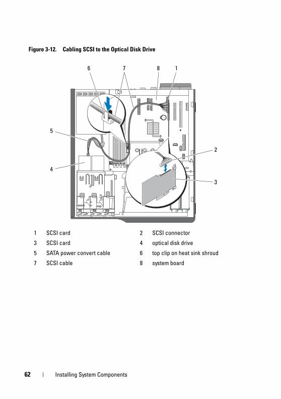
Figure 3-12. Cabling SCSI to the Optical Disk Drive
1 SCSI card 2 SCSI connector
3 SCSI card 4 optical disk drive
5 SATA power convert cable 6 top clip on heat sink shroud
7 SCSI cable 8 system board
4
76 8 1
2
3
5
62 Installing System Components
book.book Page 63 Wednesday, April 15, 2009 8:47 PM
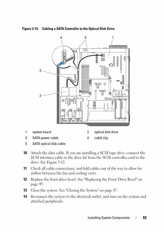
Figure 3-13. Cabling a SATA Controller to the Optical Disk Drive
10 Attach the data cable. If you are installing a SCSI tape drive, connect the SCSI interface cable in the drive kit from the SCSI controller card to the drive. See Figure 3-12.
11 Check all cable connections, and fold cables out of the way to allow for airflow between the fan and cooling vents.
12 Replace the front drive bezel. See "Replacing the Front Drive Bezel" on page 49.
13 Close the system. See "Closing the System" on page 47.
14 Reconnect the system to the electrical outlet, and turn on the system and attached peripherals.
1 system board 2 optical disk drive
3 SATA power cable 4 cable clip
5 SATA optical disk cable
54 1
3
2
Installing System Components 63
book.book Page 64 Wednesday, April 15, 2009 8:47 PM
15 (Optional) Test the drive by running the system diagnostics. See "Running the System Diagnostics" on page 127.
Hard Drives NOTE: The system’s drive configuration must consist of all SATA hard drives or all
SAS hard drives.
Hard Drive Installation Guidelines
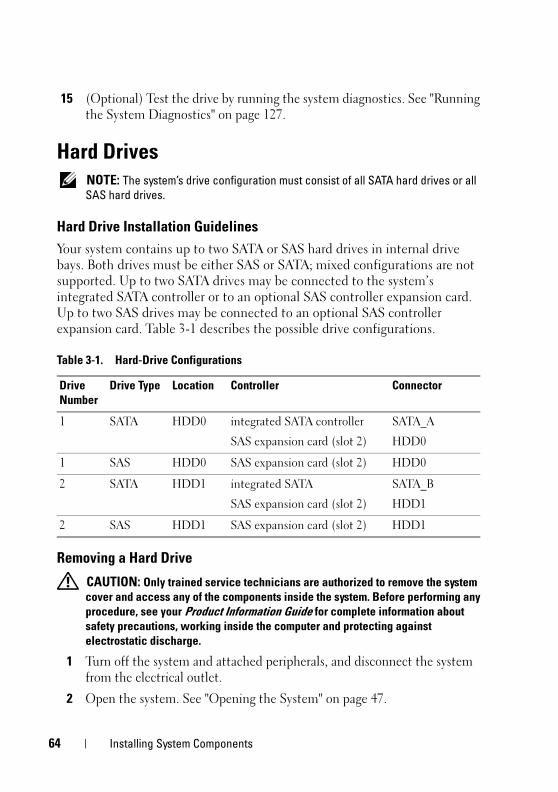
Your system contains up to two SATA or SAS hard drives in internal drive bays. Both drives must be either SAS or SATA; mixed configurations are not supported. Up to two SATA drives may be connected to the system’s integrated SATA controller or to an optional SAS controller expansion card. Up to two SAS drives may be connected to an optional SAS controller expansion card. Table 3-1 describes the possible drive configurations.
Removing a Hard Drive
CAUTION: Only trained service technicians are authorized to remove the system
cover and access any of the components inside the system. Before performing any
procedure, see your Product Information Guide for complete information about
safety precautions, working inside the computer and protecting against
electrostatic discharge.
1 Turn off the system and attached peripherals, and disconnect the system from the electrical outlet.
2 Open the system. See "Opening the System" on page 47.
Table 3-1. Hard-Drive Configurations
Drive
Number
Drive Type Location Controller Connector
1 SATA HDD0 integrated SATA controller
SAS expansion card (slot 2)
SATA_A
HDD0
1 SAS HDD0 SAS expansion card (slot 2) HDD0
2 SATA HDD1 integrated SATA
SAS expansion card (slot 2)
SATA_B
HDD1
2 SAS HDD1 SAS expansion card (slot 2) HDD1
64 Installing System Components
book.book Page 65 Wednesday, April 15, 2009 8:47 PM
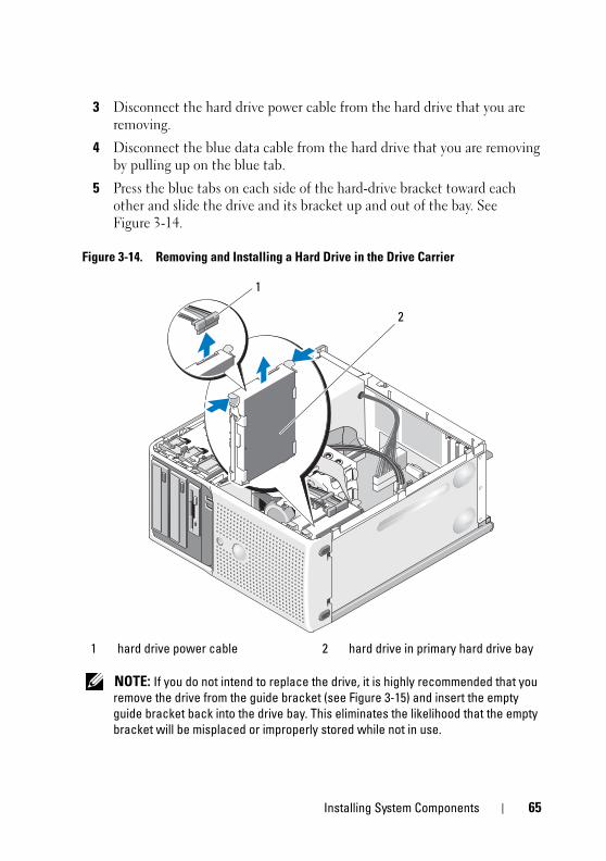
3 Disconnect the hard drive power cable from the hard drive that you are removing.
4 Disconnect the blue data cable from the hard drive that you are removing by pulling up on the blue tab.
5 Press the blue tabs on each side of the hard-drive bracket toward each other and slide the drive and its bracket up and out of the bay. See Figure 3-14.
Figure 3-14. Removing and Installing a Hard Drive in the Drive Carrier
NOTE: If you do not intend to replace the drive, it is highly recommended that you
remove the drive from the guide bracket (see Figure 3-15) and insert the empty
guide bracket back into the drive bay. This eliminates the likelihood that the empty
bracket will be misplaced or improperly stored while not in use.
1 hard drive power cable 2 hard drive in primary hard drive bay
1
2
Installing System Components 65
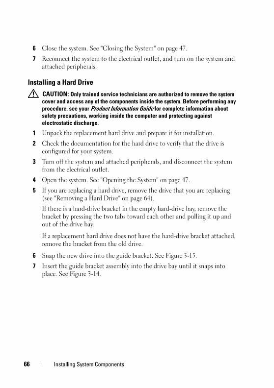
book.book Page 66 Wednesday, April 15, 2009 8:47 PM
6 Close the system. See "Closing the System" on page 47.
7 Reconnect the system to the electrical outlet, and turn on the system and attached peripherals.
Installing a Hard Drive
CAUTION: Only trained service technicians are authorized to remove the system
cover and access any of the components inside the system. Before performing any
procedure, see your Product Information Guide for complete information about
safety precautions, working inside the computer and protecting against
electrostatic discharge.
1 Unpack the replacement hard drive and prepare it for installation.
2 Check the documentation for the hard drive to verify that the drive is configured for your system.
3 Turn off the system and attached peripherals, and disconnect the system from the electrical outlet.
4 Open the system. See "Opening the System" on page 47.
5 If you are replacing a hard drive, remove the drive that you are replacing (see "Removing a Hard Drive" on page 64).
If there is a hard-drive bracket in the empty hard-drive bay, remove the bracket by pressing the two tabs toward each other and pulling it up and out of the drive bay.
If a replacement hard drive does not have the hard-drive bracket attached, remove the bracket from the old drive.
6 Snap the new drive into the guide bracket. See Figure 3-15.
7 Insert the guide bracket assembly into the drive bay until it snaps into place. See Figure 3-14.
66 Installing System Components
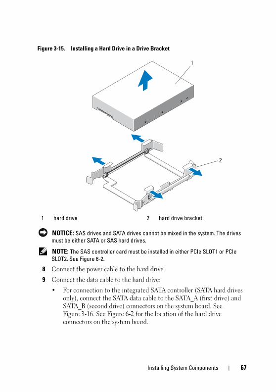
book.book Page 67 Wednesday, April 15, 2009 8:47 PM
Figure 3-15. Installing a Hard Drive in a Drive Bracket
NOTICE: SAS drives and SATA drives cannot be mixed in the system. The drives
must be either SATA or SAS hard drives.
NOTE: The SAS controller card must be installed in either PCIe SLOT1 or PCIe
SLOT2. See Figure 6-2.
8 Connect the power cable to the hard drive.
9 Connect the data cable to the hard drive:
• For connection to the integrated SATA controller (SATA hard drives only), connect the SATA data cable to the SATA_A (first drive) and SATA_B (second drive) connectors on the system board. See Figure 3-16. See Figure 6-2 for the location of the hard drive connectors on the system board.
1 hard drive 2 hard drive bracket
1
2
Installing System Components 67
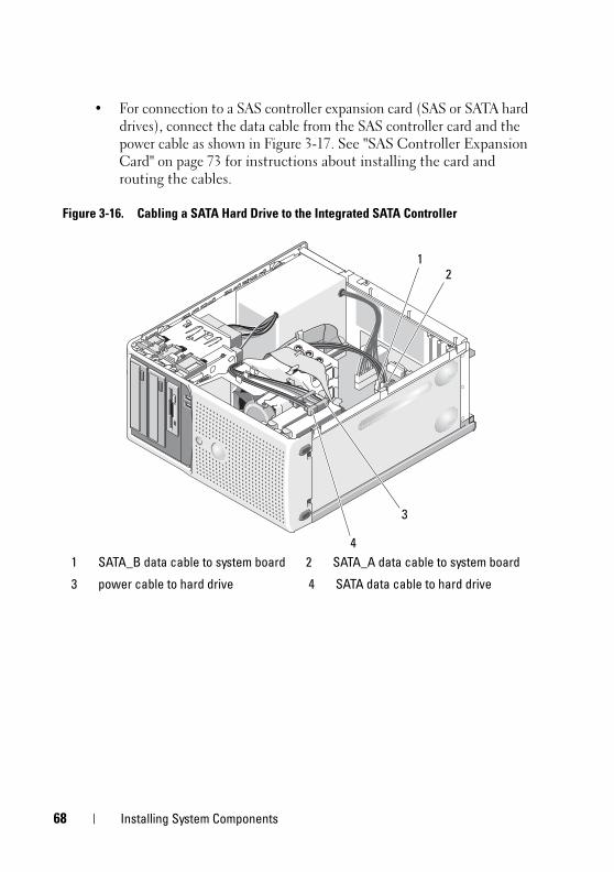
book.book Page 68 Wednesday, April 15, 2009 8:47 PM
• For connection to a SAS controller expansion card (SAS or SATA hard drives), connect the data cable from the SAS controller card and the power cable as shown in Figure 3-17. See "SAS Controller Expansion Card" on page 73 for instructions about installing the card and routing the cables.
Figure 3-16. Cabling a SATA Hard Drive to the Integrated SATA Controller
1 SATA_B data cable to system board 2 SATA_A data cable to system board
3 power cable to hard drive 4 SATA data cable to hard drive
3
4
21
68 Installing System Components
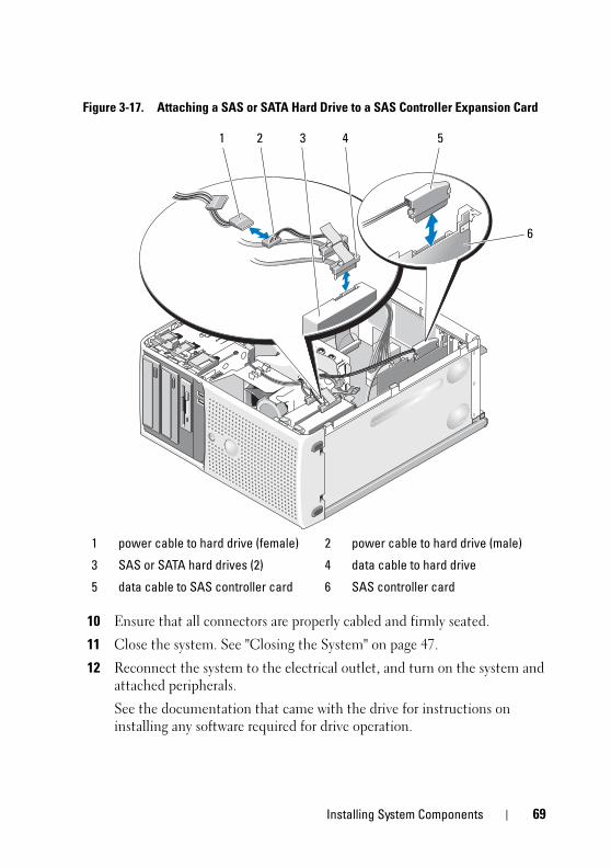
book.book Page 69 Wednesday, April 15, 2009 8:47 PM
Figure 3-17. Attaching a SAS or SATA Hard Drive to a SAS Controller Expansion Card
10 Ensure that all connectors are properly cabled and firmly seated.
11 Close the system. See "Closing the System" on page 47.
12 Reconnect the system to the electrical outlet, and turn on the system and attached peripherals.
See the documentation that came with the drive for instructions on installing any software required for drive operation.
1 power cable to hard drive (female) 2 power cable to hard drive (male)
3 SAS or SATA hard drives (2) 4 data cable to hard drive
5 data cable to SAS controller card 6 SAS controller card
5
6
3 421
Installing System Components 69
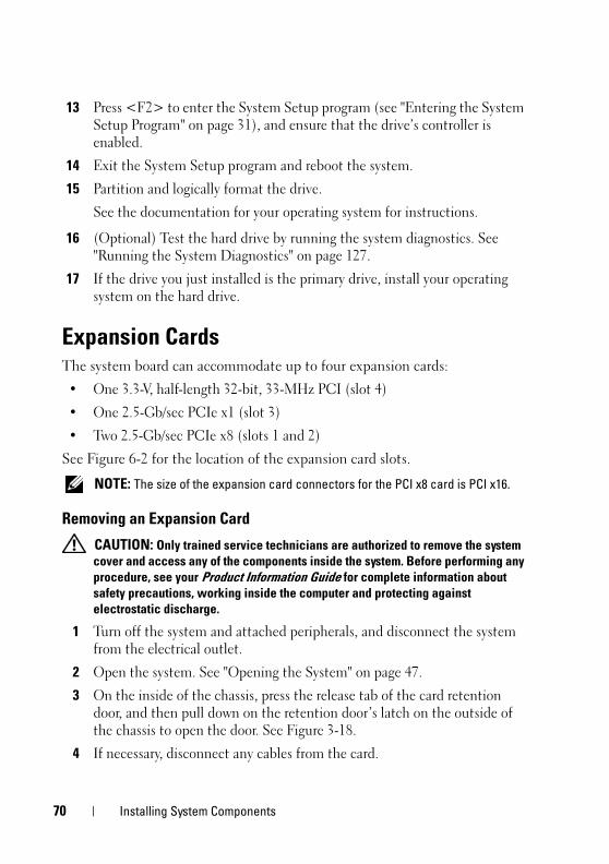
book.book Page 70 Wednesday, April 15, 2009 8:47 PM
13 Press <F2> to enter the System Setup program (see "Entering the System Setup Program" on page 31), and ensure that the drive’s controller is enabled.
14 Exit the System Setup program and reboot the system.
15 Partition and logically format the drive.
See the documentation for your operating system for instructions.
16 (Optional) Test the hard drive by running the system diagnostics. See "Running the System Diagnostics" on page 127.
17 If the drive you just installed is the primary drive, install your operating system on the hard drive.
Expansion CardsThe system board can accommodate up to four expansion cards:
• One 3.3-V, half-length 32-bit, 33-MHz PCI (slot 4)
• One 2.5-Gb/sec PCIe x1 (slot 3)
• Two 2.5-Gb/sec PCIe x8 (slots 1 and 2)
See Figure 6-2 for the location of the expansion card slots.
NOTE: The size of the expansion card connectors for the PCI x8 card is PCI x16.
Removing an Expansion Card
CAUTION: Only trained service technicians are authorized to remove the system
cover and access any of the components inside the system. Before performing any
procedure, see your Product Information Guide for complete information about
safety precautions, working inside the computer and protecting against
electrostatic discharge.
1 Turn off the system and attached peripherals, and disconnect the system from the electrical outlet.
2 Open the system. See "Opening the System" on page 47.
3 On the inside of the chassis, press the release tab of the card retention door, and then pull down on the retention door’s latch on the outside of the chassis to open the door. See Figure 3-18.
4 If necessary, disconnect any cables from the card.
70 Installing System Components
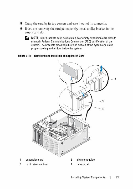
book.book Page 71 Wednesday, April 15, 2009 8:47 PM
5 Grasp the card by its top corners and ease it out of its connector.
6 If you are removing the card permanently, install a filler bracket in the empty card slot.
NOTE: Filler brackets must be installed over empty expansion card slots to
maintain Federal Communications Commission (FCC) certification of the
system. The brackets also keep dust and dirt out of the system and aid in
proper cooling and airflow inside the system.
Figure 3-18. Removing and Installing an Expansion Card
1 expansion card 2 alignment guide
3 card retention door 4 release tab
2
4
3
1
Installing System Components 71
book.book Page 72 Wednesday, April 15, 2009 8:47 PM
7 Close the card retention door to secure the remaining card(s) in the system. See Figure 3-18.
8 Close the system. See "Closing the System" on page 47.
9 Reconnect the system to the electrical outlet, and turn on the system and attached peripherals.
10 Remove the card’s device driver from the operating system.
Installing an Expansion Card
CAUTION: Only trained service technicians are authorized to remove the system
cover and access any of the components inside the system. Before performing any
procedure, see your Product Information Guide for complete information about
safety precautions, working inside the computer and protecting against
electrostatic discharge.
1 Turn off the system and attached peripherals, and disconnect the system from the electrical outlet.
2 Open the system. See "Opening the System" on page 47.
3 On the inside of the chassis, press the release tab of the card retention door, and then pull down on the retention door’s latch on the outside of the chassis to open the door. See Figure 3-18.
4 If you are installing a new card, remove the filler bracket.
NOTE: Keep this bracket in case you need to remove the expansion card.
Filler brackets must be installed over empty expansion-card slots to maintain
FCC certification of the system. The brackets also keep dust and dirt out of the
system and aid in proper cooling and airflow inside the system.
5 Prepare the card for installation.
See the documentation that came with the card for information on configuring the card, making internal connections, or otherwise customizing it for your system.
NOTE: Some NICs automatically start the system when they are connected to
a network.
6 Insert the card into the expansion card connector on the system board (SLOT1, SLOT2, SLOT3, or SLOT4) and press down firmly. Ensure that the card is fully seated in the slot and all cards and filler brackets are flush with the alignment bar. See Figure 6-2 for the location of the four expansion card connectors.
72 Installing System Components
book.book Page 73 Wednesday, April 15, 2009 8:47 PM
7 Close the card retention door to secure the card(s) in the system.
NOTICE: Do not route card cables over or behind the cards. Cables routed over the
cards can prevent the system cover from closing properly or cause damage to the
equipment.
8 Connect any cables that should be attached to the card.
See the documentation for the card for information about the card’s cable connections.
9 Close the system. See "Closing the System" on page 47.
10 Reconnect the system to the electrical outlet, and turn on the system and attached peripherals.
11 Install any device drivers required for the card as described in the documentation for the card.
SAS Controller Expansion Card
Read the installation instructions in the documentation for your SAS controller card. Install the card in expansion card connector SLOT1 or SLOT2 (see "Installing an Expansion Card" on page 72), and connect the hard-drive activity indicator cable from the card to the AUXLED1 connector on the system board (see Figure 6-2 for the connector location). Fasten the cables to the slots as indicated in Figure 3-19 to manage the slack.
Installing System Components 73
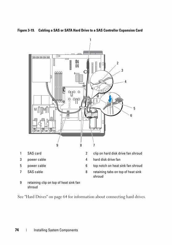
book.book Page 74 Wednesday, April 15, 2009 8:47 PM
Figure 3-19. Cabling a SAS or SATA Hard Drive to a SAS Controller Expansion Card
See "Hard Drives" on page 64 for information about connecting hard drives.
1 SAS card 2 clip on hard disk drive fan shroud
3 power cable 4 hard disk drive fan
5 power cable 6 top notch on heat sink fan shroud
7 SAS cable 8 retaining tabs on top of heat sink
shroud
9 retaining clip on top of heat sink fan
shroud
1
6
89
5
2
3
4
7
74 Installing System Components
book.book Page 75 Wednesday, April 15, 2009 8:47 PM
MemoryThe four memory module connectors on the system board can accommodate from 512 MB to 8 GB of 667-MHz and 800-MHz unbuffered ECC DDR II single or dual-rank memory modules. See Figure 6-2 for the location of the four memory module connectors.
NOTE: When installing memory, take care to install it in the proper slots according
to the configuration guidelines in Table 3-2. Installing memory in the wrong slots will
significantly reduce system performance. See Figure 6-2 for slot locations.
Memory Module Upgrade Kits
The system is upgradable to 8 GB by installing combinations of 512-MB, 1-GB, and 2-GB 667-MHz or 800-MHz unbuffered ECC DDR II single or dual-rank memory modules. You can purchase memory upgrade kits from Dell.
Memory Module Installation Guidelines
• If only one memory module is installed, it must be installed in connector DIMM_1.
• If only one memory module is installed in connector DIMM_1, its capacity can be 512 MB, 1 GB, or 2 GB.
• If more than one memory module is installed, the memory modules must be installed in pairs of matched memory size, speed, and technology.
• Memory modules must be installed in ordered pairs in connectors DIMM_1 and DIMM_2, and then DIMM_3 and DIMM_4.
• If a processor with a slower front-side bus rating than the memory is installed, the memory will operate at the processor’s slower front-side bus speed.
NOTICE: If you remove your original memory modules from the system during a
memory upgrade, keep them separate from any new memory modules that you may
have, even if you purchased the new memory modules from Dell. Use only
unbuffered ECC DDR II memory modules.
Table 3-2 illustrates memory configuration guidelines. It is important to follow the slot installation configurations shown here to achieve maximum memory performance.
Installing System Components 75
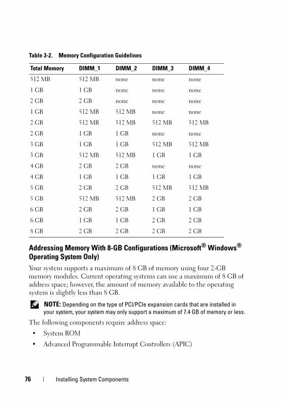
book.book Page 76 Wednesday, April 15, 2009 8:47 PM
Addressing Memory With 8-GB Configurations (Microsoft® Windows® Operating System Only)
Your system supports a maximum of 8 GB of memory using four 2-GB memory modules. Current operating systems can use a maximum of 8 GB of address space; however, the amount of memory available to the operating system is slightly less than 8 GB.
NOTE: Depending on the type of PCI/PCIe expansion cards that are installed in
your system, your system may only support a maximum of 7.4 GB of memory or less.
The following components require address space:
• System ROM
• Advanced Programmable Interrupt Controllers (APIC)
Table 3-2. Memory Configuration Guidelines
Total Memory DIMM_1 DIMM_2 DIMM_3 DIMM_4
512 MB 512 MB none none none
1 GB 1 GB none none none
2 GB 2 GB none none none
1 GB 512 MB 512 MB none none
2 GB 512 MB 512 MB 512 MB 512 MB
2 GB 1 GB 1 GB none none
3 GB 1 GB 1 GB 512 MB 512 MB
3 GB 512 MB 512 MB 1 GB 1 GB
4 GB 2 GB 2 GB none none
4 GB 1 GB 1 GB 1 GB 1 GB
5 GB 2 GB 2 GB 512 MB 512 MB
5 GB 512 MB 512 MB 2 GB 2 GB
6 GB 2 GB 2 GB 1 GB 1 GB
6 GB 1 GB 1 GB 2 GB 2 GB
8 GB 2 GB 2 GB 2 GB 2 GB
76 Installing System Components
book.book Page 77 Wednesday, April 15, 2009 8:47 PM
• Integrated PCI devices (such as NICs) and SCSI controllers
• PCI expansion cards
At start-up, the BIOS identifies the components that require address space. The BIOS dynamically calculates the amount of reserved address space required. The BIOS then subtracts the reserved address space from 8 GB to determine the amount of usable space.
• If the total installed system memory is less than the usable space, all installed system memory is available for use only by the operating system.
• If the total installed system memory is equal to or greater than the usable address space, a small portion of installed memory is available for use by the operating system.
Removing a Memory Module
CAUTION: Only trained service technicians are authorized to remove the system
cover and access any of the components inside the system. Before performing any
procedure, see your Product Information Guide for complete information about
safety precautions, working inside the computer and protecting against
electrostatic discharge.
1 Turn off the system and attached peripherals, and disconnect the system from the electrical outlet.
2 Open the system. See "Opening the System" on page 47.
3 Press out on the securing clip at each end of the memory module connector. See Figure 3-20.
4 Grasp the memory module and pull it out of the connector.
If the module is difficult to remove, gently move the module back and forth to remove it from the connector.
Installing a Memory Module
CAUTION: Only trained service technicians are authorized to remove the system
cover and access any of the components inside the system. Before performing any
procedure, see your Product Information Guide for complete information about
safety precautions, working inside the computer and protecting against
electrostatic discharge.
1 Turn off the system and attached peripherals, and disconnect the system from the electrical outlet.
Installing System Components 77
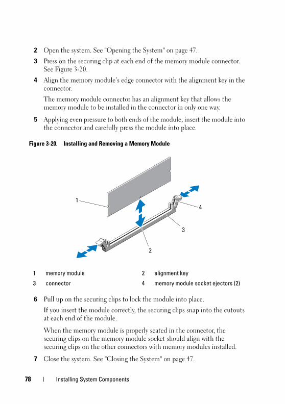
book.book Page 78 Wednesday, April 15, 2009 8:47 PM
2 Open the system. See "Opening the System" on page 47.
3 Press on the securing clip at each end of the memory module connector. See Figure 3-20.
4 Align the memory module’s edge connector with the alignment key in the connector.
The memory module connector has an alignment key that allows the memory module to be installed in the connector in only one way.
5 Applying even pressure to both ends of the module, insert the module into the connector and carefully press the module into place.
Figure 3-20. Installing and Removing a Memory Module
6 Pull up on the securing clips to lock the module into place.
If you insert the module correctly, the securing clips snap into the cutouts at each end of the module.
When the memory module is properly seated in the connector, the securing clips on the memory module socket should align with the securing clips on the other connectors with memory modules installed.
7 Close the system. See "Closing the System" on page 47.
1 memory module 2 alignment key
3 connector 4 memory module socket ejectors (2)
41
3
2
78 Installing System Components
book.book Page 79 Wednesday, April 15, 2009 8:47 PM
8 Reconnect the system to the electrical outlet, and turn on the system and attached peripherals.
The system detects that the new memory does not match the existing configuration information and generates the following message:
The amount of system memory has changed.Strike the F1 key to continue, F2 to run the setup utility
9 Press <F2> to enter the System Setup program and check the value for Memory Information. See "System Setup Options" on page 33.
The system should have changed the value for Memory Information to reflect the newly installed memory. Verify the new value. If it is correct, skip to step 13.
10 If the memory value is incorrect, turn off the system and attached peripherals, and disconnect the system from the electrical outlet.
11 Open the system. See "Opening the System" on page 47.
12 Ensure that the installed memory modules are seated properly in their connectors, and repeat step 7 through step 9.
13 When the Memory Information value is correct, press <Esc> to exit the System Setup program.
14 Run the system diagnostics to verify that the memory modules are operating properly. See "Running the System Diagnostics" on page 128.
MicroprocessorYou can upgrade the system processor to take advantage of future options in speed and functionality. The processor and its associated internal cache memory are contained in a 939-pin micro pin grid array (PGA) package.
Removing the Processor
CAUTION: Only trained service technicians are authorized to remove the system
cover and access any of the components inside the system. Before performing any
procedure, see your Product Information Guide for complete information about
safety precautions, working inside the computer and protecting against
electrostatic discharge.
Installing System Components 79
book.book Page 80 Wednesday, April 15, 2009 8:47 PM
CAUTION: The processor and heat sink can get very hot during normal operation.
Ensure that they have had sufficient time to cool before you touch them.
1 Turn off the system and attached peripherals, and disconnect the system from the electrical outlet.
2 Open the system. See "Opening the System" on page 47.
3 Detach the diskette cable that is braced on top of the shroud assembly and move it aside.
4 Using a #2 Phillips screwdriver, loosen the two captive screws holding the heat sink and shroud assembly in place.
These captive screws are adjacent to the processor cooling fan housing. See Figure 3-21.
5 Tilt the heat sink and shroud assembly away from the fan housing on its pivot bracket and lift it out.
80 Installing System Components
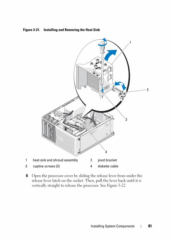
book.book Page 81 Wednesday, April 15, 2009 8:47 PM
Figure 3-21. Installing and Removing the Heat Sink
6 Open the processor cover by sliding the release lever from under the release lever latch on the socket. Then, pull the lever back until it is vertically straight to release the processor. See Figure 3-22.
1 heat sink and shroud assembly 2 pivot bracket
3 captive screws (2) 4 diskette cable
1
2
3
4
Installing System Components 81
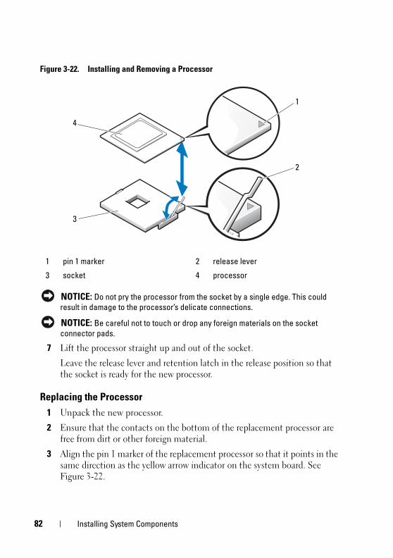
book.book Page 82 Wednesday, April 15, 2009 8:47 PM
Figure 3-22. Installing and Removing a Processor
NOTICE: Do not pry the processor from the socket by a single edge. This could
result in damage to the processor’s delicate connections.
NOTICE: Be careful not to touch or drop any foreign materials on the socket
connector pads.
7 Lift the processor straight up and out of the socket.
Leave the release lever and retention latch in the release position so that the socket is ready for the new processor.
Replacing the Processor
1 Unpack the new processor.
2 Ensure that the contacts on the bottom of the replacement processor are free from dirt or other foreign material.
3 Align the pin 1 marker of the replacement processor so that it points in the same direction as the yellow arrow indicator on the system board. See Figure 3-22.
1 pin 1 marker 2 release lever
3 socket 4 processor
3
1
2
4
82 Installing System Components
book.book Page 83 Wednesday, April 15, 2009 8:47 PM
NOTICE: Use caution when removing and installing the processor. Damaging the
processor socket connectors can damage the system board.
4 Carefully set the processor in the processor frame. Ensure that the notched edge of the processor fits securely over the matching tab on the processor frame. Do not press down on the processor. If the processor is seated correctly, it should fit snugly in the socket frame. See Figure 3-22.
5 Lower the retention latch onto the processor, and then rotate the release lever latch back toward the system board until it snaps into place.
6 Clean the thermal grease from the bottom of the heat sink.
NOTICE: Ensure that you apply new thermal grease. Applying new thermal grease
is critical to ensuring proper thermal bonding as well as optimal processor
operation.
7 Apply new thermal grease to the top of the processor.
8 Place the heat sink assembly back onto the heat sink assembly bracket and tilt the heat sink assembly down on the system board. See Figure 3-21.
9 Align the two captive screws properly with the system board, then tighten them to secure the heat sink assembly to the system board.
10 Close the system. See "Closing the System" on page 47.
11 Reconnect the system to the electrical outlet, and turn on the system and attached peripherals.
Cooling FansThe system contains two cooling fans, one for the processor and one for the card cage. Each contains a shroud that is part of the cooling fan assembly. The fan and shroud are replaced as a unit.
NOTE: If you are removing the larger processor cooling fan, you must first remove
the heat sink and shroud assembly. See "Removing the Processor" on page 79
(however, do not remove the processor) and Figure 3-24.
Installing System Components 83
book.book Page 84 Wednesday, April 15, 2009 8:47 PM
Removing the Cooling Fans
CAUTION: Only trained service technicians are authorized to remove the system
cover and access any of the components inside the system. Before performing any
procedure, see your Product Information Guide for complete information about
safety precautions, working inside the computer and protecting against
electrostatic discharge.
1 Turn off the system and attached peripherals, and disconnect the system from the electrical outlet.
2 Open the system. See "Opening the System" on page 47.
3 Disconnect the fan’s power cable from the system board.
4 If you are removing the smaller hard drive cooling fan (see Figure 3-23):
a Squeeze the two release tabs together at the top of the fan cage that attaches the fan to the chassis bracket mount.
b Lift the fan out.
NOTE: The SAS hard drive cooling fan is present only if a SAS 6i/R integrated
controller card is installed.
5 If you are removing the larger processor cooling fan:
a Remove the heat sink and shroud assembly. See "Removing the Processor" on page 79. Do not remove the processor, however.
b Press the side release tab that attaches the processor cooling fan to the chassis (see Figure 3-24).
c Press the bottom release tab and shift it forward to maneuver the bottom securing tabs out of their mounting holes (see Figure 3-24).
d Slide the fan toward the back panel and lift the fan out.
84 Installing System Components
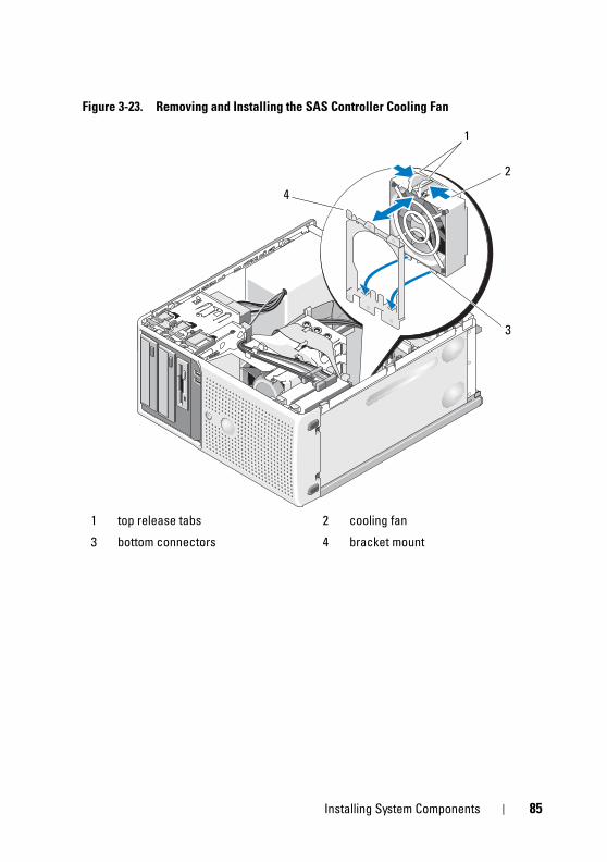
book.book Page 85 Wednesday, April 15, 2009 8:47 PM
Figure 3-23. Removing and Installing the SAS Controller Cooling Fan
1 top release tabs 2 cooling fan
3 bottom connectors 4 bracket mount
1
2
4
3
Installing System Components 85
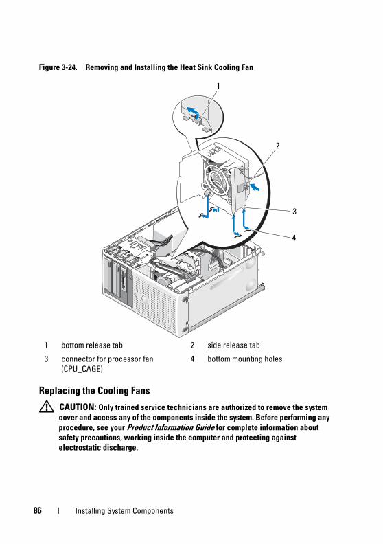
book.book Page 86 Wednesday, April 15, 2009 8:47 PM
Figure 3-24. Removing and Installing the Heat Sink Cooling Fan
Replacing the Cooling Fans
CAUTION: Only trained service technicians are authorized to remove the system
cover and access any of the components inside the system. Before performing any
procedure, see your Product Information Guide for complete information about
safety precautions, working inside the computer and protecting against
electrostatic discharge.
1 bottom release tab 2 side release tab
3 connector for processor fan
(CPU_CAGE)
4 bottom mounting holes
2
3
1
4
86 Installing System Components
book.book Page 87 Wednesday, April 15, 2009 8:47 PM
If you are replacing the hard drive cooling fan:
1 Align the bottom connectors on the replacement fan with the mounting holes in the system chassis.
2 Squeeze the top two release tabs and maneuver the assembly forward so that it locks into place.
If you are replacing the processor cooling fan:
1 Align the bottom connectors on the replacement fan with the mounting holes in the system chassis. Align the slots on the side of the replacement fan with the securing tabs on the chassis bracket mount.
2 Slide the fan toward the front panel until it snaps into place.
3 Secure the cables into the slots on the heat sink fan shroud to manage unwanted slack. See Figure 3-25.
4 Attach the fan cable to the system board. See Figure 6-2 for the location of the connector.
Installing System Components 87
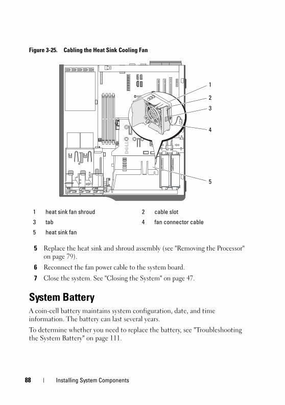
book.book Page 88 Wednesday, April 15, 2009 8:47 PM
Figure 3-25. Cabling the Heat Sink Cooling Fan
5 Replace the heat sink and shroud assembly (see "Removing the Processor" on page 79).
6 Reconnect the fan power cable to the system board.
7 Close the system. See "Closing the System" on page 47.
System BatteryA coin-cell battery maintains system configuration, date, and time information. The battery can last several years.
To determine whether you need to replace the battery, see "Troubleshooting the System Battery" on page 111.
1 heat sink fan shroud 2 cable slot
3 tab 4 fan connector cable
5 heat sink fan
3
4
5
1
2
88 Installing System Components
book.book Page 89 Wednesday, April 15, 2009 8:47 PM
You can operate your system without a battery; however, without a battery, the configuration information is erased if the system is turned off or unplugged from the electrical outlet. In this case, you must enter the System Setup program and reset the configuration options.
CAUTION: A new battery can explode if it is incorrectly installed. Replace the
battery only with the same or equivalent type recommended by the manufacturer.
Discard used batteries according to the manufacturer’s instructions.
Removing the System Battery
CAUTION: Only trained service technicians are authorized to remove the system
cover and access any of the components inside the system. Before performing any
procedure, see your Product Information Guide for complete information about
safety precautions, working inside the computer and protecting against
electrostatic discharge.
1 Enter the System Setup program and record the option settings on the System Setup screens. See "Using the System Setup Program" on page 31.
2 Turn off the system, including any attached peripherals, and disconnect the system from the electrical outlet.
3 Open the system. See "Opening the System" on page 47.
4 See Figure 6-2 for the location of the system battery and then remove any cables that block access to the battery.
NOTICE: If you use a blunt, nonconductive object to depress the tab next to the
battery, be careful not to touch the system board with the object. Ensure that the
object is inserted between the battery and the tab before you attempt to depress
the tab. Do not pry out the battery. You may damage the system board by prying off
the socket or by breaking circuit traces on the system board.
5 Press the tab on the battery socket to release the battery, then lift the battery out of the socket. See Figure 3-26.
Installing System Components 89
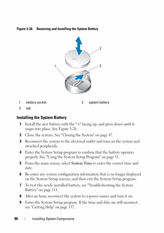
book.book Page 90 Wednesday, April 15, 2009 8:47 PM
Figure 3-26. Removing and Installing the System Battery
Installing the System Battery
1 Install the new battery with the "+" facing up, and press down until it snaps into place. See Figure 3-26.
2 Close the system. See "Closing the System" on page 47.
3 Reconnect the system to the electrical outlet and turn on the system and attached peripherals.
4 Enter the System Setup program to confirm that the battery operates properly. See "Using the System Setup Program" on page 31.
5 From the main screen, select System Time to enter the correct time and date.
6 Re-enter any system configuration information that is no longer displayed on the System Setup screens, and then exit the System Setup program.
7 To test the newly installed battery, see "Troubleshooting the System Battery" on page 111.
8 After an hour, reconnect the system to a power source and turn it on.
9 Enter the System Setup program. If the time and date are still incorrect, see "Getting Help" on page 137.
1 battery socket 2 system battery
3 tab
2
31
90 Installing System Components
book.book Page 91 Wednesday, April 15, 2009 8:47 PM
10 Properly dispose of the old battery. For more information, see your Product
Information Guide.
Power Supply
Removing the Power Supply
CAUTION: Only trained service technicians are authorized to remove the system
cover and access any of the components inside the system. Before performing any
procedure, see your Product Information Guide for complete information about
safety precautions, working inside the computer and protecting against
electrostatic discharge.
1 Turn off the system and attached peripherals, and disconnect the system from the electrical outlet.
2 Open the system. See "Opening the System" on page 47.
3 Depending on your system configuration, disconnect the following power cables:
• P1 and P2 to the system board
• P3 and P5 to the SATA or SAS drives
• P7 to the diskette drive
• P8, P9, and P10 to the optical and tape drives
NOTE: Note the routing of the DC power cables underneath the tabs in the
system frame as you release the tabs and remove the cables from the system
board and drives. You must route these cables properly when you replace
them to prevent their being pinched or crimped.
4 Remove the heat sink and shroud assembly. Loosen the two captive screws holding the heat sink and shroud assembly in place.
These captive screws are adjacent to the processor cooling fan housing. See Figure 3-21.
5 Tilt the heat sink and shroud assembly away from the fan housing and lift it out.
6 Remove the I/O panel and SATA cables (if present) attached to the routing clips on the side of the power supply.
Installing System Components 91
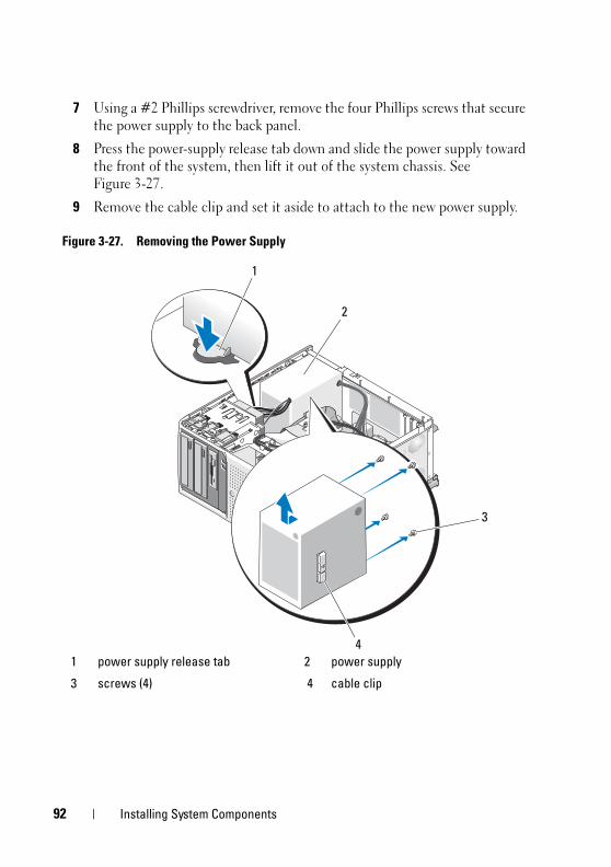
book.book Page 92 Wednesday, April 15, 2009 8:47 PM
7 Using a #2 Phillips screwdriver, remove the four Phillips screws that secure the power supply to the back panel.
8 Press the power-supply release tab down and slide the power supply toward the front of the system, then lift it out of the system chassis. See Figure 3-27.
9 Remove the cable clip and set it aside to attach to the new power supply.
Figure 3-27. Removing the Power Supply
1 power supply release tab 2 power supply
3 screws (4) 4 cable clip
3
1
2
4
92 Installing System Components
book.book Page 93 Wednesday, April 15, 2009 8:47 PM
Installing the Power Supply
1 Attach the cable clip to the new power supply.
2 Align the power supply mounting holes with the mounting holes on the back panel.
3 Slide the power supply toward the back panel until it snaps into place over the power-supply release tab.
4 Using a #2 Phillips screwdriver, install the four Phillips screws that secure the power supply to the back panel.
5 Reattach the I/O panel and SATA cables (if present) to the routing clip on the side of the power supply.
6 Depending on your system configuration, connect the following power cables:
• P1 and P2 to the system board
• P3 and P5 to the SATA or SAS drives
• P7 to the diskette drive
• P8, P9, and P10 to the optical and tape drives
7 Close the system. See "Closing the System" on page 47.
Chassis Intrusion Switch
Removing the Chassis Intrusion Switch
CAUTION: Only trained service technicians are authorized to remove the system
cover and access any of the components inside the system. Before performing any
procedure, see your Product Information Guide for complete information about
safety precautions, working inside the computer and protecting against
electrostatic discharge.
1 Turn off the system and attached peripherals, and disconnect the system from the electrical outlet.
2 Open the system. See "Opening the System" on page 47.
3 Disconnect the chassis intrusion switch cable from the INTRUSION connector on the system board. See Figure 3-28.
Installing System Components 93
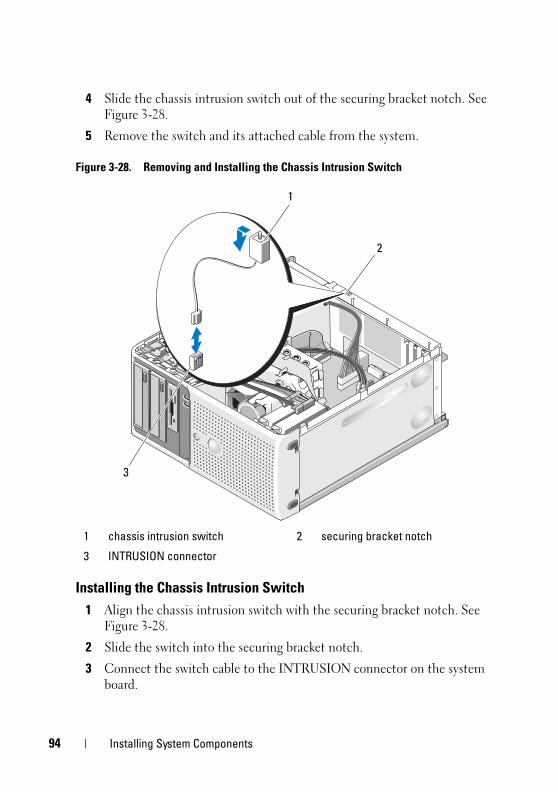
94
book.book Page 94 Wednesday, April 15, 2009 8:47 PM
4 Slide the chassis intrusion switch out of the securing bracket notch. See Figure 3-28.
5 Remove the switch and its attached cable from the system.
Figure 3-28. Removing and Installing the Chassis Intrusion Switch
Installing the Chassis Intrusion Switch
1 Align the chassis intrusion switch with the securing bracket notch. See Figure 3-28.
2 Slide the switch into the securing bracket notch.
3 Connect the switch cable to the INTRUSION connector on the system board.
1 chassis intrusion switch 2 securing bracket notch
3 INTRUSION connector
1
2
3
Installing System Components
book.book Page 95 Wednesday, April 15, 2009 8:47 PM
4 Close the system. See "Closing the System" on page 47.
5 Reconnect the system to the electrical outlet, and turn on the system.
Bezel (Service Only Parts Procedure)
Removing the Bezel
CAUTION: Only trained service technicians are authorized to remove the system
cover and access any of the components inside the system. Before performing any
procedure, see your Product Information Guide for complete information about
safety precautions, working inside the computer and protecting against
electrostatic discharge.
1 Turn off the system and attached peripherals, and disconnect the system from the electrical outlet.
2 Open the system. See "Opening the System" on page 47.
3 Remove the heat sink and shroud assembly. See "Removing the Processor" on page 79. Do not remove the processor, however.
4 Remove the large processor cooling fan. See "Removing the Cooling Fans" on page 84.
5 Remove the two bezel release screws. See Figure 3-29.
6 Slide the bezel toward the top of the system, then lift it outward.
Installing System Components 95
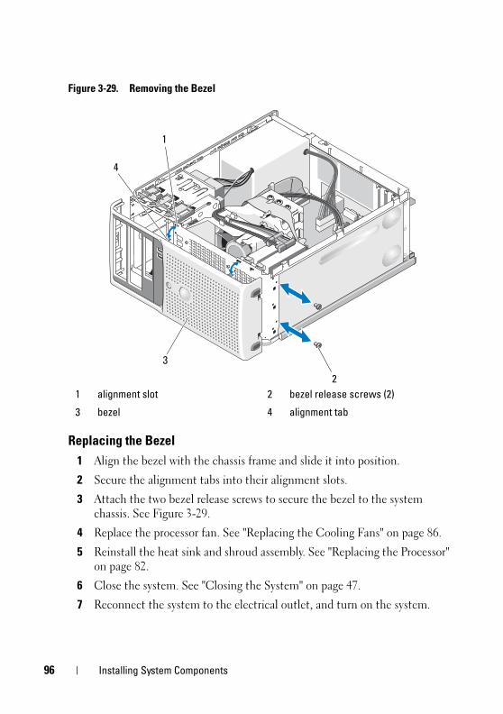
96
book.book Page 96 Wednesday, April 15, 2009 8:47 PM
Figure 3-29. Removing the Bezel
Replacing the Bezel
1 Align the bezel with the chassis frame and slide it into position.
2 Secure the alignment tabs into their alignment slots.
3 Attach the two bezel release screws to secure the bezel to the system chassis. See Figure 3-29.
4 Replace the processor fan. See "Replacing the Cooling Fans" on page 86.
5 Reinstall the heat sink and shroud assembly. See "Replacing the Processor" on page 82.
6 Close the system. See "Closing the System" on page 47.
7 Reconnect the system to the electrical outlet, and turn on the system.
1 alignment slot 2 bezel release screws (2)
3 bezel 4 alignment tab
3
2
1
4
Installing System Components
book.book Page 97 Wednesday, April 15, 2009 8:47 PM
I/O Panel Assembly (Service Only Parts Procedure)
CAUTION: Only trained service technicians are authorized to remove the system
cover and access any of the components inside the system. Before performing any
procedure, see your Product Information Guide for complete information about
safety precautions, working inside the computer and protecting against
electrostatic discharge.
Removing the I/O Panel Assembly
1 Turn off the system and attached peripherals, and disconnect the system from the electrical outlet.
2 Open the system. See "Opening the System" on page 47.
3 Remove the heat sink and shroud assembly. See "Removing the Processor" on page 79. Do not remove the processor, however.
4 Remove the processor cooling fan. See "Removing the Cooling Fans" on page 84.
5 Remove the front bezel. See "Removing the Bezel" on page 95.
NOTICE: Carefully note the routing of each cable before you disconnect it, so that
you are sure to re-route cables correctly.
6 Disconnect the I/O panel ribbon cable from the I/O panel connector by pulling the yellow cable loop.
7 Remove the mounting screw holding the I/O panel assembly to the front chassis. See Figure 3-30.
8 Lift the I/O panel assembly out of the system.
Installing System Components 97
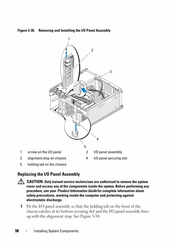
book.book Page 98 Wednesday, April 15, 2009 8:47 PM
Figure 3-30. Removing and Installing the I/O Panel Assembly
Replacing the I/O Panel Assembly
CAUTION: Only trained service technicians are authorized to remove the system
cover and access any of the components inside the system. Before performing any
procedure, see your Product Information Guide for complete information about
safety precautions, working inside the computer and protecting against
electrostatic discharge.
1 Fit the I/O panel assembly so that the holding tab on the front of the chassis catches at its bottom securing slot and the I/O panel assembly lines up with the alignment stop. See Figure 3-30.
1 screw on the I/O panel 2 I/O panel assembly
3 alignment stop on chassis 4 I/O panel securing slot
5 holding tab on the chassis
1
4
2
3
5
98 Installing System Components
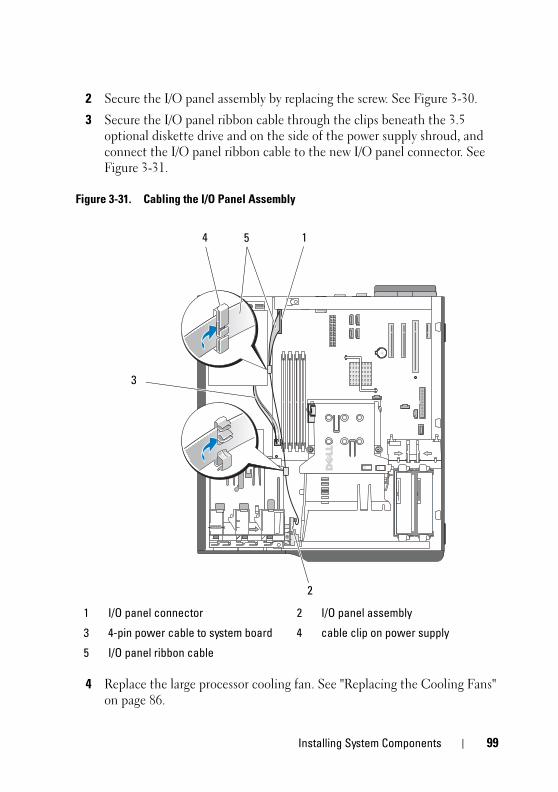
book.book Page 99 Wednesday, April 15, 2009 8:47 PM
2 Secure the I/O panel assembly by replacing the screw. See Figure 3-30.
3 Secure the I/O panel ribbon cable through the clips beneath the 3.5 optional diskette drive and on the side of the power supply shroud, and connect the I/O panel ribbon cable to the new I/O panel connector. See Figure 3-31.
Figure 3-31. Cabling the I/O Panel Assembly
4 Replace the large processor cooling fan. See "Replacing the Cooling Fans" on page 86.
1 I/O panel connector 2 I/O panel assembly
3 4-pin power cable to system board 4 cable clip on power supply
5 I/O panel ribbon cable
4
2
5 1
3
Installing System Components 99
1
book.book Page 100 Wednesday, April 15, 2009 8:47 PM
5 Replace the heat sink and shroud assembly. See "Replacing the Processor" on page 82.
NOTE: To prevent damaging the processor, clean the heat sink to remove any
thermal grease and then apply fresh thermal grease to the processor before
installing the heat sink.
6 Close the system. See "Closing the System" on page 47.
7 Reconnect the system to the electrical outlet, and turn on the system.
System Board (Service Only Parts Procedure) CAUTION: Only trained service technicians are authorized to remove the system
cover and access any of the components inside the system. Before performing any
procedure, see your Product Information Guide for complete information about
safety precautions, working inside the computer and protecting against
electrostatic discharge.
CAUTION: The heat sink can get hot during operation. To avoid burns, ensure that
the system has sufficient time to cool before removing the system board.
Removing the System Board
1 Turn off the system and attached peripherals, and disconnect the system from the electrical outlet.
2 Open the system. See "Opening the System" on page 47.
3 Depending on your configuration, disconnect the following cables from the system board. See Figure 6-2 for connector locations.
• Two power-supply cables from the POWER and POWER12V1 connectors
• Diskette data cable from the FLOPPY connector
• I/O panel cable from the CONTROL-PANEL connector
• Processor cooling fan cable from the FAN1 connector
• Card cage cooling fan cable from the FAN2 connector
• SATA hard-drive data cable(s) from the SATA connector(s)
• Intrusion switch cable from the INTRUSION connector
00 Installing System Components
book.book Page 101 Wednesday, April 15, 2009 8:47 PM
4 Remove all expansion cards and any attached cables. See "Removing an Expansion Card" on page 70.
5 Remove all memory modules. See "Memory" on page 75.
NOTE: Record the memory-module socket locations to ensure proper
reinstallation of the memory modules.
CAUTION: The processor and heat sink can become extremely hot. Allow
sufficient time for the processor and heat sink to cool before handling.
NOTICE: To prevent damaging the processor, do not pry the heat sink off of the
processor.
6 Remove the processor. See "Removing the Processor" on page 79.
7 Using a #2 Phillips screwdriver, remove the six system board mounting screws that secure the system board to the chassis. See Figure 6-2.
8 Using a #2 Phillips screwdriver, remove the two processor heat sink pivot mount screws and remove the pivot mount from the system board. See Figure 6-2. The heat sink pivot mount screws are green and are longer than the system board mounting screws.
9 Carefully route any loose cables away from the edges of the system board.
10 Gently slide the system board toward the front of the system, then lift the system board up and out of the chassis.
Installing the System Board
1 After removing the old system board, lower the new system board into the chassis, aligning the I/O ports on the system board with the I/O connector openings on the back panel of the chassis.
2 Using a #2 Phillips screwdriver, install the six screws on the system board that secure it to the chassis. See Figure 6-2.
3 Using a #2 Phillips screwdriver, attach the processor heat sink pivot mount to the system board. See Figure 6-2.
NOTICE: To prevent damaging the processor, clean the heat sink to remove any
thermal grease and then apply fresh thermal grease to the processor before
installing the heat sink.
4 Replace the processor, and the heat sink and shroud assembly. See "Replacing the Processor" on page 82.
Installing System Components 101
1
book.book Page 102 Wednesday, April 15, 2009 8:47 PM
5 Install the memory modules in the same sockets from which they were removed. See "Installing a Memory Module" on page 77.
6 Install the expansion cards and connect any cables. See "Installing an Expansion Card" on page 72.
7 Depending on your configuration, connect the following cables that you removed in "Removing the System Board" on page 100. See Figure 6-2.
• Two power-supply cables to the POWER and POWER12V1 connectors
• If applicable, diskette data cable to the FLOPPY connector
• I/O panel cable to the CONTROL-PANEL connector
• Processor cooling fan cable to the FAN1 connector
• Card cage cooling fan cable to the FAN2 connector
• SATA hard-drive data cable(s) to the SATA connector(s)
• Intrusion switch cable from the INTRUSION connector
8 Close the system. See "Closing the System" on page 47.
9 Reconnect the system to the electrical outlet, and turn on the system.
02 Installing System Components
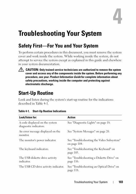
book.book Page 103 Wednesday, April 15, 2009 8:47 PM
Troubleshooting Your System
Safety First—For You and Your SystemTo perform certain procedures in this document, you must remove the system cover and work inside the system. While working inside the system, do not attempt to service the system except as explained in this guide and elsewhere in your system documentation.
CAUTION: Only trained service technicians are authorized to remove the system
cover and access any of the components inside the system. Before performing any
procedure, see your Product Information Guide for complete information about
safety precautions, working inside the computer and protecting against
electrostatic discharge.
Start-Up Routine Look and listen during the system's start-up routine for the indications described in Table 4-1.
Table 4-1. Start-Up Routine Indications
Look/listen for: Action
A code displayed on the system diagnostic indicators.
See "Diagnostic Lights" on page 18.
An error message displayed on the monitor.
See "System Messages" on page 20.
The monitor's power indicator. See "Troubleshooting the Video Subsystem" on page 104.
The keyboard indicators. See "Troubleshooting the Keyboard" on page 105.
The USB diskette drive activity indicator.
See "Troubleshooting a Diskette Drive" on page 116.
The USB CD drive activity indicator. See "Troubleshooting an Optical Drive" on page 118.
Troubleshooting Your System 103
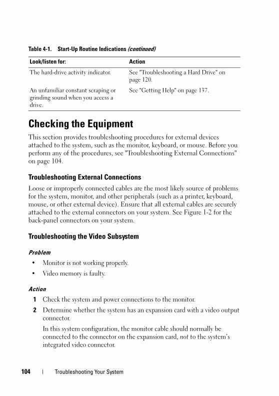
1
book.book Page 104 Wednesday, April 15, 2009 8:47 PM
Checking the EquipmentThis section provides troubleshooting procedures for external devices attached to the system, such as the monitor, keyboard, or mouse. Before you perform any of the procedures, see "Troubleshooting External Connections" on page 104.
Troubleshooting External Connections
Loose or improperly connected cables are the most likely source of problems for the system, monitor, and other peripherals (such as a printer, keyboard, mouse, or other external device). Ensure that all external cables are securely attached to the external connectors on your system. See Figure 1-2 for the back-panel connectors on your system.
Troubleshooting the Video Subsystem
Problem
• Monitor is not working properly.
• Video memory is faulty.
Action
1 Check the system and power connections to the monitor.
2 Determine whether the system has an expansion card with a video output connector.
In this system configuration, the monitor cable should normally be connected to the connector on the expansion card, not to the system’s integrated video connector.
The hard-drive activity indicator. See "Troubleshooting a Hard Drive" on page 120.
An unfamiliar constant scraping or grinding sound when you access a drive.
See "Getting Help" on page 137.
Table 4-1. Start-Up Routine Indications (continued)
Look/listen for: Action
04 Troubleshooting Your System
book.book Page 105 Wednesday, April 15, 2009 8:47 PM
To verify that the monitor is connected to the correct video connector, turn off the system and wait for 1 minute, then connect the monitor to the other video connector and turn the system on again.
3 Run the appropriate online diagnostic test. See "Using Dell PowerEdge Diagnostics" on page 127.
If the tests run successfully, the problem is not related to video hardware.
If the tests fail, see "Getting Help" on page 137.
Troubleshooting the Keyboard
Problem
• System message indicates a problem with the keyboard.
• Keyboard is not functioning properly.
Action
1 Enter the System Setup program and ensure that the USB ports are enabled. See "Using the System Setup Program" on page 31.
2 Examine the keyboard and its cable for signs of damage.
3 Swap the faulty keyboard with a working keyboard.
If the problem is resolved, replace the faulty keyboard. See "Getting Help" on page 137.
4 Run the appropriate online diagnostic test. See "Using Dell PowerEdge Diagnostics" on page 127.
If the problem is not resolved, see "Getting Help" on page 137.
Troubleshooting the Mouse
Problem
• System message indicates a problem with the mouse.
• Mouse is not functioning properly.
Troubleshooting Your System 105
1
book.book Page 106 Wednesday, April 15, 2009 8:47 PM
Action
1 Run the appropriate online diagnostic test. See "Using Dell PowerEdge Diagnostics" on page 127.
If the test fails, continue to the next step.
2 Examine the mouse and its cable for signs of damage.
If the mouse is not damaged, go to step 4.
If the mouse is damaged, continue to the next step.
3 Swap the faulty mouse with a working mouse.
If the problem is resolved, replace the faulty mouse. See "Getting Help" on page 137.
4 Enter the System Setup program and ensure that the mouse controller is enabled. See "Using the System Setup Program" on page 31.
If the problem is not resolved, see "Getting Help" on page 137.
Troubleshooting Serial I/O Problems
Problem
• Error message indicates a problem with a serial port.
• Device connected to a serial port is not operating properly.
Action
1 Enter the System Setup program and ensure that the serial port is enabled and configured correctly for your application. See "Using the System Setup Program" on page 31.
2 If the problem is confined to a particular application, see the application documentation for specific port configuration requirements that the program may require.
3 Run the appropriate online diagnostic test. See "Running the System Diagnostics" on page 127.
If the tests run successfully but the problem persists, see "Troubleshooting a USB Device" on page 107.
06 Troubleshooting Your System
book.book Page 107 Wednesday, April 15, 2009 8:47 PM
Troubleshooting a Serial I/O Device
Problem
• Device connected to the serial port is not operating properly.
Action
1 Turn off the system and any peripheral devices connected to the serial port.
2 Swap the serial interface cable with a working cable, and turn on the system and the serial device.
If the problem is resolved, replace the interface cable. See "Getting Help" on page 137.
3 Turn off the system and the serial device, and swap the device with a comparable device.
4 Turn on the system and the serial device.
If the problem is resolved, replace the serial device. See "Getting Help" on page 137.
If the problem persists, see "Getting Help" on page 137.
Troubleshooting a USB Device
Problem
• System message indicates a problem with a USB device.
• Device connected to a USB port is not operating properly.
Action
1 Enter the System Setup program and ensure that the USB ports are enabled. See "Using the System Setup Program" on page 31.
2 Turn off the system and any USB devices.
3 Disconnect the USB devices, and connect the malfunctioning device to the other USB connector.
Troubleshooting Your System 107
1
book.book Page 108 Wednesday, April 15, 2009 8:47 PM
4 Turn on the system and the reconnected device.
If the problem is resolved, the USB connector might be defective. See "Getting Help" on page 137.
5 If possible, swap the interface cable with a working cable.
If the problem is resolved, replace the interface cable. See "Getting Help" on page 137.
6 Turn off the system and the USB device, and swap the device with a comparable device.
7 Turn on the system and the USB device.
If the problem is resolved, replace the USB device. See "Getting Help" on page 137.
If the problem persists, see "Getting Help" on page 137.
Troubleshooting a NIC
Problem
• NIC cannot communicate with network.
Action
1 Run the appropriate online diagnostic test. See "Using Dell PowerEdge Diagnostics" on page 127.
2 Check the appropriate indicator on the NIC connector. See "NIC Indicator Codes" on page 16.
• If the link indicator does not light, check all cable connections.
• If the activity indicator does not light, the network driver files might be damaged or missing.
Remove and reinstall the drivers if applicable. See the NIC's documentation.
• Change the autonegotiation setting, if possible.
• Use another connector on the switch or hub.
If you are using a NIC card instead of an integrated NIC, see the documentation for the NIC card.
08 Troubleshooting Your System
book.book Page 109 Wednesday, April 15, 2009 8:47 PM
3 Ensure that the appropriate drivers are installed and the protocols are bound. See the NIC's documentation.
4 Enter the System Setup program and confirm that the NICs are enabled. See "Using the System Setup Program" on page 31.
5 Ensure that the NICs, hubs, and switches on the network are all set to the same data transmission speed. See the network equipment documentation.
6 Ensure that all network cables are of the proper type and do not exceed the maximum length.
If the problem persists, see "Getting Help" on page 137.
Troubleshooting a Wet System
Problem
• Liquid spilled on the system.
• Excessive humidity.
Action
CAUTION: Only trained service technicians are authorized to remove the system
cover and access any of the components inside the system. Before performing any
procedure, see your Product Information Guide for complete information about
safety precautions, working inside the computer and protecting against
electrostatic discharge.
1 Turn off the system and attached peripherals, and disconnect the system from the electrical outlet.
2 Open the system. See "Opening the System" on page 47.
3 Remove all expansion cards installed in the system. See "Removing an Expansion Card" on page 70.
4 Let the system dry thoroughly for at least 24 hours.
5 Close the system. See "Closing the System" on page 47.
6 Reconnect the system to the electrical outlet, and turn on the system and attached peripherals.
If the system does not start properly, see "Getting Help" on page 137.
Troubleshooting Your System 109
1
book.book Page 110 Wednesday, April 15, 2009 8:47 PM
7 If the system starts properly, shut down the system and reinstall all of the expansion cards that you removed. See "Installing an Expansion Card" on page 72.
8 Run the appropriate online diagnostic test. See "Using Dell PowerEdge Diagnostics" on page 127.
If the tests fail, see "Getting Help" on page 137.
Troubleshooting a Damaged System
Problem
• System was dropped or damaged.
Action
CAUTION: Only trained service technicians are authorized to remove the system
cover and access any of the components inside the system. Before performing any
procedure, see your Product Information Guide for complete information about
safety precautions, working inside the computer and protecting against
electrostatic discharge.
1 Open the system. See "Opening the System" on page 47.
2 Ensure that the following components are properly installed:
• Expansion cards
• Power supply
• Fans
• Processors and heat sinks
• Optional installed drivers
• Memory modules
3 Ensure that all cables are properly connected.
4 Close the system. See "Closing the System" on page 47.
5 Run the system board tests in the system diagnostics. See "Running the System Diagnostics" on page 127.
If the tests fail, see "Getting Help" on page 137.
10 Troubleshooting Your System
book.book Page 111 Wednesday, April 15, 2009 8:47 PM
Troubleshooting the System Battery
Problem
• System message indicates a problem with the battery.
• System Setup program loses system configuration information.
• System date and time do not remain current.
NOTE: If the system is turned off for long periods of time (for weeks or months), the
NVRAM may lose its system configuration information. This situation is caused by a
defective battery.
Action
1 Re-enter the time and date through the System Setup program. See "Using the System Setup Program" on page 31.
2 Turn off the system and disconnect it from the electrical outlet for at least one hour.
3 Reconnect the system to the electrical outlet and turn on the system.
4 Enter the System Setup program. See "Using the System Setup Program" on page 31.
If the date and time are not correct in the System Setup program, replace the battery. See "System Battery" on page 88.
If the problem is not resolved by replacing the battery, see "Getting Help" on page 137.
NOTE: Some software may cause the system time to speed up or slow down. If the
system seems to operate normally except for the time kept in the System Setup
program, the problem may be caused by software rather than by a defective
battery.
Troubleshooting Your System 111
1
book.book Page 112 Wednesday, April 15, 2009 8:47 PM
Troubleshooting Power Supply
Problem
• Power-supply fault indicator is blinking amber.
Action
CAUTION: Only trained service technicians are authorized to remove the system
cover and access any of the components inside the system. Before performing any
procedure, see your Product Information Guide for complete information about
safety precautions, working inside the computer and protecting against
electrostatic discharge.
1 Run the appropriate online diagnostics test. See "Running the System Diagnostics" on page 127.
2 Turn off the system and attached peripherals, and disconnect the system from the electrical outlet.
3 Open the system. See "Opening the System" on page 47.
4 Locate the faulty power supply.
The power supply's fault indicator is lit. See "Power Supply Indicators" on page 17.
NOTICE: Setting the voltage selection switch to an improper setting can damage
your system.
5 Ensure that the power supply is properly installed by removing and reinstalling it. See "Installing the Power Supply" on page 93.
NOTE: After installing a power supply, allow several seconds for the system
to recognize the power supply and to determine if it is working properly. The
power indicator turns green to signify that the power supply is functioning
properly.
6 If the problem is resolved, close the system. See "Closing the System" on page 47.
If the problem persists, remove the faulty power supply. See "Removing the Power Supply" on page 91.
7 Install a new power supply. See "Installing the Power Supply" on page 93.
If the problem persists, see "Getting Help" on page 137.
12 Troubleshooting Your System
book.book Page 113 Wednesday, April 15, 2009 8:47 PM
Troubleshooting System Cooling Problems
Problem
• Systems management software issues a fan-related error message.
Action
Ensure that none of the following conditions exist:
• System cover, drive blank, or front or back filler panel is removed.
• Ambient temperature is too high.
• External airflow is obstructed.
• Cables inside the system obstruct airflow.
• An individual cooling fan is removed or has failed. See "Troubleshooting a Fan" on page 113.
Troubleshooting a Fan
Problem
• System-status indicator is amber.
• System management software issues a fan-related error message.
Action
CAUTION: Only trained service technicians are authorized to remove the system
cover and access any of the components inside the system. Before performing any
procedure, see your Product Information Guide for complete information about
safety precautions, working inside the computer and protecting against
electrostatic discharge.
1 Run the appropriate diagnostic test. See "Using Dell PowerEdge Diagnostics" on page 127.
2 Turn off the system and attached peripherals, and disconnect the system from the electrical outlet.
3 Open the system. See "Opening the System" on page 47.
CAUTION: The cooling fans are hot-pluggable. To maintain proper cooling while
the system is on, only replace one fan at a time.
Troubleshooting Your System 113
1
book.book Page 114 Wednesday, April 15, 2009 8:47 PM
4 Locate the faulty fan indicated by the diagnostic software or the fan indicator that is blinking amber. For the identification number of each fan, see "Removing and Installing the Heat Sink Cooling Fan" on page 86.
5 Ensure that the faulty fan's power cable is firmly attached to the fan power connector. For a hot-plug fan, remove and reseat the fan. See "Cooling Fans" on page 83.
NOTE: Wait 30 seconds for the system to recognize the fan and determine
whether it is working properly.
6 Reconnect the system to its electrical outlet, and turn on the system and attached peripherals.
7 If the problem is not resolved, install a new fan. See "Cooling Fans" on page 83.
If the replacement fan is working properly, close the system. See "Closing the System" on page 47.
If the replacement fan does not operate, see "Getting Help" on page 137.
Troubleshooting System Memory
Problem
• Faulty memory module.
• Faulty system board.
• Diagnostic indicator code indicates a problem with system memory.
Action
CAUTION: Only trained service technicians are authorized to remove the system
cover and access any of the components inside the system. Before performing any
procedure, see your Product Information Guide for complete information about
safety precautions, working inside the computer and protecting against
electrostatic discharge.
1 If the system is operational, run the appropriate online diagnostic test. See "Using Dell PowerEdge Diagnostics" on page 127.
If diagnostics indicates a fault, follow the corrective actions provided by the diagnostic program. If the problem is not resolved or if the system is not operational, continue to the next step.
14 Troubleshooting Your System
book.book Page 115 Wednesday, April 15, 2009 8:47 PM
2 Turn off the system and attached peripherals, unplug the system from the power source and press the power button, and then reconnect the system to power.
3 Turn on the system and attached peripherals and, as the system boots, note the messages on the screen.
If an error messages appears indicating a fault with a specific memory module, go to step 12.
If any other system message appears that indicates a nonspecific memory problem, continue to the next step.
4 Enter the System Setup program and check the system memory setting. See "Using the System Setup Program" on page 31.
If the installed memory does not match the amount of memory shown in the System Setup program, proceed to the next step.
If the memory settings and installed memory indicate no problems, go to step 12.
5 Turn off the system and attached peripherals, and disconnect the system from the electrical outlet.
6 Open the system. See "Opening the System" on page 47.
7 Ensure that the memory banks are populated correctly. See "Memory Module Installation Guidelines" on page 75.
If the memory modules are populated correctly, continue to the next step.
8 Reseat the memory modules in their sockets. See "Installing a Memory Module" on page 77.
9 Close the system. See "Closing the System" on page 47.
10 Reconnect the system to its electrical outlet, and turn on the system and attached peripherals.
11 Enter the System Setup program and check the system memory setting. See "Using the System Setup Program" on page 31.
If the amount of memory installed still does not match the system memory setting, proceed to the next step.
12 Turn off the system and attached peripherals, and disconnect the system from its electrical outlet.
Troubleshooting Your System 115
1
book.book Page 116 Wednesday, April 15, 2009 8:47 PM
13 Open the system. See "Opening the System" on page 47.
NOTE: Several configurations for the memory modules exist; see "Memory Module
Installation Guidelines" on page 75.
14 If a diagnostic test or error message indicates a specific memory module as faulty, swap or replace the module. Otherwise, swap the memory module in the first DIMM socket with a module of the same type and capacity that is known to be good. See "Installing a Memory Module" on page 77.
15 Close the system. See "Closing the System" on page 47.
16 Reconnect the system to its electrical outlet, and turn on the system and attached peripherals.
17 As the system boots, observe any error message that appears and the diagnostic indicators on the front of the system.
18 If the memory problem is still indicated, repeat step 12 through step 17 for each memory module installed.
If the problem persists, see "Getting Help" on page 137.
Troubleshooting a Diskette Drive
Problem
• Error message indicates a diskette drive problem.
Action
CAUTION: Only trained service technicians are authorized to remove the system
cover and access any of the components inside the system. Before performing any
procedure, see your Product Information Guide for complete information about
safety precautions, working inside the computer and protecting against
electrostatic discharge.
1 Enter the System Setup program and verify that the diskette drive is configured correctly. See "Using the System Setup Program" on page 31.
2 Remove the bezel. See "Removing the Bezel" on page 95.
3 Run the appropriate online diagnostic test. See "Using Dell PowerEdge Diagnostics" on page 127.
4 Turn off the system and attached peripherals, and disconnect the system from the electrical outlet.
16 Troubleshooting Your System
book.book Page 117 Wednesday, April 15, 2009 8:47 PM
5 Open the system. See "Opening the System" on page 47.
6 Ensure that the diskette drive interface cable is securely connected to the diskette drive and the system board.
7 Ensure that a power cable is properly connected to the drive.
8 Close the system. See "Closing the System" on page 47.
9 Reconnect the system to the electrical outlet, and turn on the system and attached peripherals.
10 Run the appropriate online diagnostic test to see whether the diskette drive works correctly.
If the problem persists, continue with the following steps.
11 Turn off the system and attached peripherals, and disconnect the system from its electrical outlet.
12 Open the system. See "Opening the System" on page 47.
13 Remove all expansion cards installed in the system. See "Removing an Expansion Card" on page 70.
14 Close the system. See "Closing the System" on page 47.
15 Reconnect the system to the electrical outlet, and turn on the system and attached peripherals.
16 Run the appropriate online diagnostic test to see whether the diskette drive works correctly.
If the tests run successfully, an expansion card may be conflicting with the diskette drive logic, or an expansion card may be faulty. Continue to the next step.
If the tests fail, see "Getting Help" on page 137.
17 Turn off the system and attached peripherals, and disconnect the system from the electrical outlet.
18 Open the system. See "Opening the System" on page 47.
19 Reinstall one of the expansion cards you removed in step 13. See "Installing an Expansion Card" on page 72.
20 Close the system. See "Closing the System" on page 47.
21 Reconnect the system to the electrical outlet, and turn on the system and attached peripherals.
Troubleshooting Your System 117
1
book.book Page 118 Wednesday, April 15, 2009 8:47 PM
22 Run the appropriate online diagnostic test to see whether the diskette drive works correctly.
23 Repeat step 17 through step 22 until all expansion cards are reinstalled or one of the expansion cards causes the tests to fail.
If the problem is not resolved, see "Getting Help" on page 137.
Troubleshooting an Optical Drive
Problem
• System cannot read data from a CD or DVD in an optical drive.
• Optical drive indicator does not blink during boot.
Action
CAUTION: Only trained service technicians are authorized to remove the system
cover and access any of the components inside the system. Before performing any
procedure, see your Product Information Guide for complete information about
safety precautions, working inside the computer and protecting against
electrostatic discharge.
1 Remove the bezel. See "Removing the Bezel" on page 95.
2 Try using a different CD or DVD that you know works properly.
3 Enter the System Setup program and ensure that the drive’s IDE controller is enabled. See "Using the System Setup Program" on page 31.
4 Run the appropriate online diagnostic test. See "Using Dell PowerEdge Diagnostics" on page 127.
5 Turn off the system and attached peripherals, and disconnect the system from the electrical outlet.
6 Open the system. See "Opening the System" on page 47.
7 Ensure that the interface cable is securely connected to the optical drive and to the controller.
8 Ensure that a power cable is properly connected to the drive.
9 Close the system. See "Closing the System" on page 47.
18 Troubleshooting Your System
book.book Page 119 Wednesday, April 15, 2009 8:47 PM
10 Reconnect the system to the electrical outlet, and turn on the system and attached peripherals.
If the problem is not resolved, see "Getting Help" on page 137.
Troubleshooting an External SCSI Tape Drive
Problem
• Defective tape drive
• Defective tape cartridge
• Missing or corrupted tape-backup software or tape drive device driver
• Defective SCSI controller
Action
1 Remove the tape cartridge you were using when the problem occurred, and replace it with a tape cartridge that you know works.
2 Ensure that the SCSI device drivers for the tape drive are installed and are configured correctly. See "Installing an Optical or Tape Drive" on page 60.
3 Reinstall the tape-backup software as instructed in the tape-backup software documentation.
4 Ensure that the tape drive’s interface/DC power cable is connected to the tape drive and SCSI controller card.
5 Verify that the tape drive is configured for a unique SCSI ID number and that the tape drive is terminated or not terminated, based on the interface cable used to connect the drive.
See the documentation for the tape drive for instructions on selecting the SCSI ID number and enabling or disabling termination.
6 Run the appropriate online diagnostics tests. See "Using Dell PowerEdge Diagnostics" on page 127.
7 Open or remove the bezel. See "Removing the Bezel" on page 95.
8 Turn off the system and attached peripherals, and disconnect the system from the electrical outlet.
Troubleshooting Your System 119
1
book.book Page 120 Wednesday, April 15, 2009 8:47 PM
CAUTION: Only trained service technicians are authorized to remove the system
cover and access any of the components inside the system. Before performing any
procedure, see your Product Information Guide for complete information about
safety precautions, working inside the computer and protecting against
electrostatic discharge.
9 Open the system. See "Opening the System" on page 47.
10 Ensure that the SCSI controller card is firmly seated in its connector. See "Installing an Expansion Card" on page 72.
11 Close the system. See "Closing the System" on page 47.
12 Reconnect the system to the electrical outlet, and turn on the system and attached peripherals.
13 If the problem is not resolved, see the documentation for the tape drive for additional troubleshooting instructions.
14 If you cannot resolve the problem, see "Getting Help" on page 137 for information on obtaining technical assistance.
Troubleshooting a Hard Drive
Problem
• Device driver error.
• One or more hard drives not recognized by the system.
Action
CAUTION: Only trained service technicians are authorized to remove the system
cover and access any of the components inside the system. Before performing any
procedure, see your Product Information Guide for complete information about
safety precautions, working inside the computer and protecting against
electrostatic discharge.
NOTICE: This troubleshooting procedure can destroy data stored on the hard
drive. Before you proceed, back up all files on the hard drive.
1 Run the appropriate online diagnostics test. See "Using Dell PowerEdge Diagnostics" on page 127.
Depending on the results of the diagnostics test, proceed as needed through the following steps.
20 Troubleshooting Your System
book.book Page 121 Wednesday, April 15, 2009 8:47 PM
2 If you are experiencing problems with multiple hard drives, skip to step 6. For a problem with a single hard drive, continue to the next step.
3 If your system has a SAS RAID controller, perform the following steps.
a Restart the system and press <Ctrl><R> to enter the host adapter configuration utility program.
See the documentation supplied with the host adapter for information about the configuration utility.
b Ensure that the hard drive has been configured correctly for the RAID.
c Exit the configuration utility and allow the system to boot to the operating system.
4 Ensure that the required device drivers for your SAS controller card or SAS RAID controller are installed and are configured correctly. See the operating system documentation for more information.
5 Verify that the controller is enabled and the drives appear in the System Setup program. See "Using the System Setup Program" on page 31.
6 Check the cable connections inside the system:
a Turn off the system, including any attached peripherals, and disconnect the system from the electrical outlet.
b Open the system. See "Opening the System" on page 47.
c Verify that the cable connections between the hard drive(s) and the drive controller are correct, whether the connections are to the SATA connectors on the system board, a SAS expansion card, or a SAS RAID controller. See "Hard Drives" on page 64.
d Verify that the SAS or SATA cables are securely seated in their connectors.
e Close the system. See "Closing the System" on page 47.
f Reconnect the system to the electrical outlet, and turn on the system and attached peripherals.
If the problem persists, see "Getting Help" on page 137.
Troubleshooting Your System 121
1
book.book Page 122 Wednesday, April 15, 2009 8:47 PM
Troubleshooting a SAS or SAS RAID Controller NOTE: When troubleshooting a SAS RAID controller, also see the documentation
for your operating system and the controller.
Problem
• Error message indicates a problem with the SAS or SAS RAID controller.
• SAS or SAS RAID controller performs incorrectly or not at all.
Action
CAUTION: Only trained service technicians are authorized to remove the system
cover and access any of the components inside the system. Before performing any
procedure, see your Product Information Guide for complete information about
safety precautions, working inside the computer and protecting against
electrostatic discharge.
1 Run the appropriate online diagnostic test. See "Using Dell PowerEdge Diagnostics" on page 127.
2 Enter the System Setup program and ensure that the SAS or SAS RAID controller is enabled. See "Using the System Setup Program" on page 31.
3 Restart the system and press the applicable key sequence to enter the configuration utility program:
• <Ctrl><C> for a SAS controller
• <Ctrl><R> for a SAS RAID controller
See the controller's documentation for information about configuration settings.
4 Check the configuration settings, make any necessary corrections, and restart the system.
If the problem is not resolved, continue to the next step.
5 Turn off the system and attached peripherals, and disconnect the system from its electrical outlet.
6 Open the system. See "Opening the System" on page 47.
7 Ensure that the controller card is firmly seated into the system board connector. See "Installing an Expansion Card" on page 72.
22 Troubleshooting Your System
book.book Page 123 Wednesday, April 15, 2009 8:47 PM
8 If you have a SAS RAID controller, ensure that the following RAID components are properly installed and connected:
• Memory module
• Battery
9 Verify that the cable connections between the hard drives and the SAS controller are correct. See "Hard Drives" on page 64.
Ensure that the cables are firmly connected to the SAS controller and the hard drives.
10 Close the system. See "Closing the System" on page 47.
11 Reconnect the system to its electrical outlet, and turn on the system and attached peripherals. If the problem persists, see "Getting Help" on page 137.
Troubleshooting Expansion Cards NOTE: When troubleshooting an expansion card, see the documentation for your
operating system and the expansion card.
Problem
• Error message indicates a problem with an expansion card.
• Expansion card performs incorrectly or not at all.
Action
CAUTION: Only trained service technicians are authorized to remove the system
cover and access any of the components inside the system. Before performing any
procedure, see your Product Information Guide for complete information about
safety precautions, working inside the computer and protecting against
electrostatic discharge.
1 Run the appropriate online diagnostic test for the expansion card which is exhibiting issues. See "Using Dell PowerEdge Diagnostics" on page 127. Follow any recommended actions provided by the diagnostics. If the problem persists, go to the next step.
2 Open or remove the bezel. See "Removing the Bezel" on page 95.
3 Turn off the system and attached peripherals, and disconnect the system from the electrical outlet.
Troubleshooting Your System 123
1
book.book Page 124 Wednesday, April 15, 2009 8:47 PM
4 Open the system. See "Opening the System" on page 47.
5 Ensure that each expansion card is firmly seated in its connector. See "Installing an Expansion Card" on page 72.
6 Close the system. See "Closing the System" on page 47.
7 Reconnect the system to the electrical outlet, and turn on the system and attached peripherals.
If the problem persists, go to the next step.
8 Turn off the system and attached peripherals, and disconnect the system from the electrical outlet.
9 Open the system. See "Opening the System" on page 47.
10 Remove all expansion cards in the system. See "Removing an Expansion Card" on page 70.
NOTE: If your operating system is running off a disk controller card (such as a SAS
controller card), do not remove it.
11 Close the system. See "Closing the System" on page 47.
12 Reconnect the system to the electrical outlet, and turn on the system and attached peripherals.
13 Run the appropriate online diagnostic test.
If the tests fail, see "Getting Help" on page 137.
14 For each expansion card you removed in step 10, perform the following steps:
a Turn off the system and attached peripherals, and disconnect the system from the electrical outlet.
b Open the system. See "Opening the System" on page 47.
c Reinstall one of the expansion cards.
d Close the system. See "Closing the System" on page 47.
e Reconnect the system to the electrical outlet, and turn on the system and attached peripherals.
f Run the appropriate online diagnostic test.
If the tests fail, repeat step 14 for each expansion card until you are able to single out the faulty expansion card.
If the tests fail for all expansion cards, see "Getting Help" on page 137.
24 Troubleshooting Your System
book.book Page 125 Wednesday, April 15, 2009 8:47 PM
Troubleshooting the Microprocessor
Problem
• Error message indicates a processor problem.
• Diagnostic indicator code indicates a problem with the processor or system board.
• A heat sink is not installed for the processor.
Action
CAUTION: Only trained service technicians are authorized to remove the system
cover and access any of the components inside the system. Before performing any
procedure, see your Product Information Guide for complete information about
safety precautions, working inside the computer and protecting against
electrostatic discharge.
1 If possible, run the appropriate online diagnostics test. See "Using Dell PowerEdge Diagnostics" on page 127.
2 Turn off the system and attached peripherals, and disconnect the system from the electrical outlet.
3 Open the system. See "Opening the System" on page 47.
4 Ensure that the processor and heat sink are properly installed. See "Replacing the Processor" on page 82.
5 Close the system. See "Closing the System" on page 47.
6 Reconnect the system to the electrical outlet, and turn on the system and attached peripherals.
7 If possible, run the appropriate online diagnostic test. See "Running the System Diagnostics" on page 127.
If the tests fail or the problem persists, continue to the next step.
8 Turn off the system and attached peripherals, and disconnect the system from the electrical outlet.
9 Open the system. See "Opening the System" on page 47.
10 Replace the processor. See "Replacing the Processor" on page 82.
11 Close the system. See "Closing the System" on page 47.
Troubleshooting Your System 125
1
book.book Page 126 Wednesday, April 15, 2009 8:47 PM
12 Reconnect the system to the electrical outlet, and turn on the system and attached peripherals.
13 Run the appropriate online diagnostic test. See "Running the System Diagnostics" on page 127.
If the problem persists, the system board is faulty. See "Getting Help" on page 137.
26 Troubleshooting Your System
book.book Page 127 Wednesday, April 15, 2009 8:47 PM
Running the System DiagnosticsIf you experience a problem with your system, run the diagnostics before calling for technical assistance. The purpose of the diagnostics is to test your system's hardware without requiring additional equipment or risking data loss. If you are unable to fix the problem yourself, service and support personnel can use diagnostics test results to help you solve the problem.
Using Dell PowerEdge DiagnosticsTo assess a system problem, first use the online Dell™ PowerEdge™ Diagnostics. Dell PowerEdge Diagnostics is a suite of diagnostic programs, or test modules, that include diagnostic tests on chassis and storage components such as hard drives, physical memory, communications and printer ports, NICs, CMOS, and more. If you are unable to identify the problem using the PowerEdge Diagnostics, then use the system diagnostics.
The files required to run PowerEdge Diagnostics for systems running supported Microsoft® Windows® and Linux operating systems are available at support.dell.com and on the CDs that came with your system. For information about using diagnostics, see the Dell PowerEdge Diagnostics User's Guide.
System Diagnostics FeaturesThe system diagnostics provides a series of menus and options for particular device groups or devices. The system diagnostics menus and options allow you to:
• Run tests individually or collectively.
• Control the sequence of tests.
• Repeat tests.
• Display, print, or save test results.
• Temporarily suspend testing if an error is detected or terminate testing when a user-defined error limit is reached.
• View help messages that briefly describe each test and its parameters.
Running the System Diagnostics 127
1
book.book Page 128 Wednesday, April 15, 2009 8:47 PM
• View status messages that inform you if tests are completed successfully.
• View error messages that inform you of problems encountered during testing.
When to Use the System DiagnosticsIf a major component or device in the system does not operate properly, component failure may be indicated. As long as the microprocessor and the system's input/output devices (monitor, keyboard, and diskette drive) are functioning, you can use the system diagnostics to help identify the problem.
Running the System DiagnosticsThe system diagnostics is run from the utility partition on your hard drive.
NOTICE: Use the system diagnostics to test only your system. Using this program
with other systems may cause invalid results or error messages. In addition, use
only the program that came with your system (or an updated version of that
program).
1 As the system boots, press <F10> during POST.
2 From the utility partition main menu, select Run System Diagnostics, or select Run Memory Diagnostics if you are troubleshooting memory.
When you start the system diagnostics, a message is displayed stating that the diagnostics are initializing. Next, the Diagnostics menu appears. The menu allows you to run all or specific diagnostics tests or to exit the system diagnostics.
NOTE: Before you read the rest of this section, start the system diagnostics so that
you can see the utility on your screen.
System Diagnostics Testing OptionsClick the testing option in the Main Menu window. Table 5-1 provides a brief explanation of testing options.
28 Running the System Diagnostics
book.book Page 129 Wednesday, April 15, 2009 8:47 PM
Using the Custom Test OptionsWhen you select Custom Test in the Main Menu window, the Customize window appears and allows you to select the device(s) to be tested, select specific options for testing, and view the test results.
Selecting Devices for Testing
The left side of the Customize window lists devices that can be tested. Devices are grouped by device type or by module, depending on the option you select. Click the (+) next to a device or module to view its components. Click (+) on any component to view the tests that are available. Clicking a device, rather than its components, selects all of the components of the device for testing.
NOTE: After you select all the devices and components that you want to test,
highlight All Devices and then click Run Tests.
Selecting Diagnostics Options
Use the Diagnostics Options area to select how you want to test a device. You can set the following options:
• Non-Interactive Tests Only — When checked, runs only tests that require no user intervention.
• Quick Tests Only — When checked, runs only the quick tests on the device. Extended tests will not run when you select this option.
• Show Ending Timestamp — When checked, time stamps the test log.
Table 5-1. System Diagnostics Testing Options
Testing Option Function
Express Test Performs a quick check of the system. This option runs device tests that do not require user interaction. Use this option to quickly identify the source of your problem.
Extended Test Performs a more thorough check of the system. This test can take an hour or longer.
Custom Test Tests a particular device.
Information Displays test results.
Running the System Diagnostics 129
1
book.book Page 130 Wednesday, April 15, 2009 8:47 PM
• Test Iterations — Selects the number of times the test is run.
• Log output file pathname — When checked, enables you to specify where the test log file is saved.
Viewing Information and Results
The tabs in the Customize window provide information about the test and the test results. The following tabs are available:
• Results — Displays the test that ran and the result.
• Errors — Displays any errors that occurred during the test.
• Help — Displays information about the currently selected device, component, or test.
• Configuration — Displays basic configuration information about the currently selected device.
• Parameters — If applicable, displays parameters that you can set for the test.
30 Running the System Diagnostics
book.book Page 131 Wednesday, April 15, 2009 8:47 PM
Jumpers and ConnectorsThis section provides specific information about the system jumpers and describes the connectors on the various boards in the system.
System Board Jumpers CAUTION: Only trained service technicians are authorized to remove the system
cover and access any of the components inside the system. Before performing any
procedure, see your Product Information Guide for complete information about
safety precautions, working inside the computer and protecting against
electrostatic discharge.
Figure 6-1 shows the location of the configuration jumpers on the system board. Table 6-1 lists the jumper settings.
Jumpers and Connectors 131
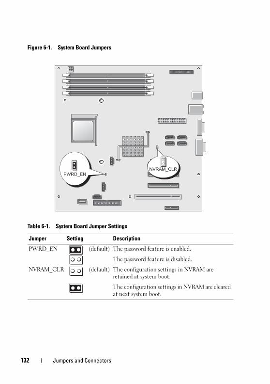
1
book.book Page 132 Wednesday, April 15, 2009 8:47 PM
Figure 6-1. System Board Jumpers
Table 6-1. System Board Jumper Settings
Jumper Setting Description
PWRD_EN (default) The password feature is enabled.
The password feature is disabled.
NVRAM_CLR (default) The configuration settings in NVRAM are retained at system boot.
The configuration settings in NVRAM are cleared at next system boot.
32 Jumpers and Connectors
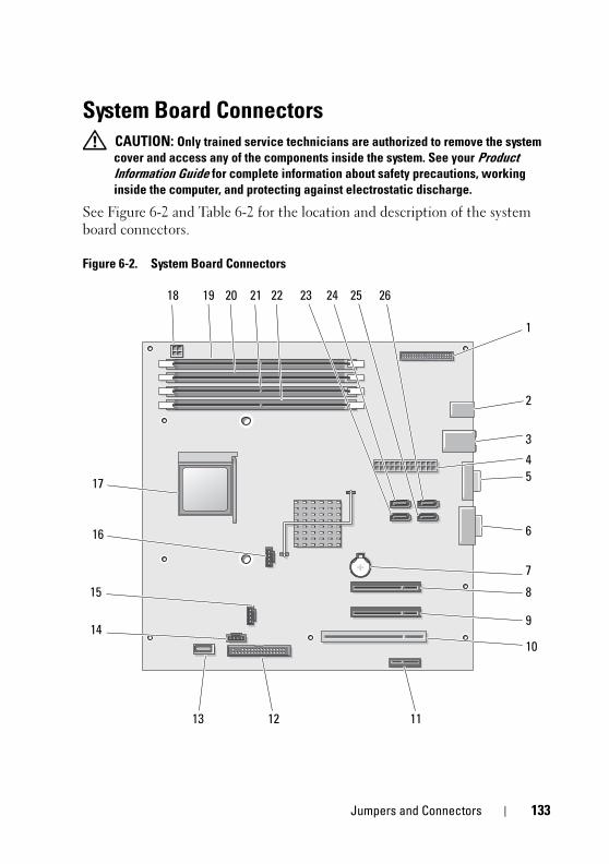
book.book Page 133 Wednesday, April 15, 2009 8:47 PM
System Board Connectors CAUTION: Only trained service technicians are authorized to remove the system
cover and access any of the components inside the system. See your Product
Information Guide for complete information about safety precautions, working
inside the computer, and protecting against electrostatic discharge.
See Figure 6-2 and Table 6-2 for the location and description of the system board connectors.
Figure 6-2. System Board Connectors
1
2
3
5
6
4
7
8
10
1112
15
14
13
18 19 20 21 22
17
23 24 25 26
9
16
Jumpers and Connectors 133
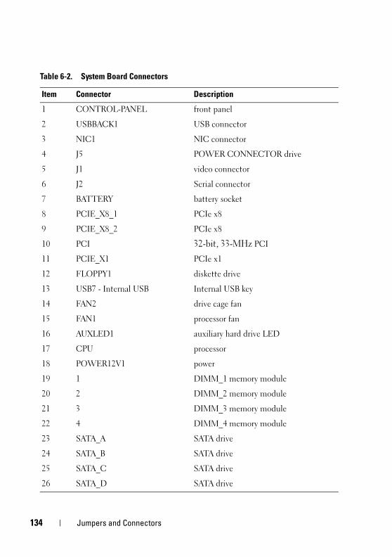
1
book.book Page 134 Wednesday, April 15, 2009 8:47 PM
Table 6-2. System Board Connectors
Item Connector Description
1 CONTROL-PANEL front panel
2 USBBACK1 USB connector
3 NIC1 NIC connector
4 J5 POWER CONNECTOR drive
5 J1 video connector
6 J2 Serial connector
7 BATTERY battery socket
8 PCIE_X8_1 PCIe x8
9 PCIE_X8_2 PCIe x8
10 PCI 32-bit, 33-MHz PCI
11 PCIE_X1 PCIe x1
12 FLOPPY1 diskette drive
13 USB7 - Internal USB Internal USB key
14 FAN2 drive cage fan
15 FAN1 processor fan
16 AUXLED1 auxiliary hard drive LED
17 CPU processor
18 POWER12V1 power
19 1 DIMM_1 memory module
20 2 DIMM_2 memory module
21 3 DIMM_3 memory module
22 4 DIMM_4 memory module
23 SATA_A SATA drive
24 SATA_B SATA drive
25 SATA_C SATA drive
26 SATA_D SATA drive
34 Jumpers and Connectors
book.book Page 135 Wednesday, April 15, 2009 8:47 PM
Disabling a Forgotten PasswordThe password jumper on the system board enables the system password features or disables them and clears any password(s) currently in use.
CAUTION: Only trained service technicians are authorized to remove the system
cover and access any of the components inside the system. See your Product
Information Guide for complete information about safety precautions, working
inside the computer, and protecting against electrostatic discharge.
1 Turn off the system and attached peripherals, and disconnect the system from the electrical outlet.
2 Open the system. See "Opening the System" on page 47.
3 Move the PWRD_EN jumper to the disabled position.
See Figure 6-1 to locate the password jumper on the system board.
4 Close the system. See "Closing the System" on page 47.
5 Reconnect the system to the electrical outlet, and turn on the system.
The existing passwords are not disabled (erased) until the system boots with the password jumper plug removed. However, before you assign a new system and/or setup password, you must install the jumper plug.
NOTE: If you assign a new system and/or setup password with the jumper
plug still removed, the system disables the new password(s) the next time it
boots.
6 Turn off the system, including any attached peripherals, and disconnect the system from the electrical outlet.
7 Open the system. See "Opening the System" on page 47.
8 Move the PWRD_EN jumper from the disabled position to the enabled position.
9 Close the system, reconnect the system to the electrical outlet, and turn on the system.
10 Assign a new system and/or setup password.
To assign a new password using the System Setup program, see "Using the System Password" on page 40.
Jumpers and Connectors 135

1
book.book Page 136 Wednesday, April 15, 2009 8:47 PM
36 Jumpers and Connectors
book.book Page 137 Wednesday, April 15, 2009 8:47 PM
Getting Help
Obtaining AssistanceIf you experience a problem with your computer, you can complete the following steps to diagnose and troubleshoot the problem:
1 See "Troubleshooting Your System" on page 103 for information and procedures that pertain to the problem your computer is experiencing.
2 See "Running the System Diagnostics" on page 127 for procedures on how to run Dell Diagnostics.
3 Fill out the "Diagnostics Checklist" on page 141.
4 Use Dell's extensive suite of online services available at Dell Support (support.dell.com) for help with installation and troubleshooting procedures. See "Online Services" on page 138 for a more extensive list of Dell Support online.
5 If the preceding steps have not resolved the problem, see "Contacting Dell" on page 142.
NOTE: Call Dell Support from a telephone near or at the computer so that the
support staff can assist you with any necessary procedures.
NOTE: Dell's Express Service Code system may not be available in all countries.
When prompted by Dell's automated telephone system, enter your Express Service Code to route the call directly to the proper support personnel. If you do not have an Express Service Code, open the Dell Accessories folder, double-click the Express Service Code icon, and follow the directions.
For instructions on using the Dell Support, see "Support Service" on page 139.
NOTE: Some of the following services are not always available in all locations
outside the continental U.S. Call your local Dell representative for information on
availability.
Getting Help 137
1
book.book Page 138 Wednesday, April 15, 2009 8:47 PM
Online Services
You can learn about Dell products and services on the following websites:
www.dell.com
www.dell.com/ap (Asian/Pacific countries only)
www.dell.com/jp (Japan only)
www.euro.dell.com (Europe only)
www.dell.com/la (Latin American and Caribbean countries)
www.dell.ca (Canada only)
You can access Dell Support through the following websites and e-mail addresses:
• Dell Support websites
support.dell.com
support.jp.dell.com (Japan only)
support.euro.dell.com (Europe only)
• Dell Support e-mail addresses
[email protected] (Latin America and Caribbean countries only)
[email protected] (Asian/Pacific countries only)
• Dell Marketing and Sales e-mail addresses
[email protected] (Asian/Pacific countries only)
[email protected] (Canada only)
• Anonymous file transfer protocol (FTP)
ftp.dell.com
Log in as user: anonymous, and use your e-mail address as your password.
38 Getting Help
book.book Page 139 Wednesday, April 15, 2009 8:47 PM
Automated Order-Status Service
To check on the status of any Dell products that you have ordered, you can go to support.dell.com, or you can call the automated order-status service. A recording prompts you for the information needed to locate and report on your order. For the telephone number to call for your region, see "Contacting Dell" on page 142.
Support Service
Dell's support service is available 24 hours a day, 7 days a week, to answer your questions about Dell hardware. Our support staff use computer-based diagnostics to provide fast, accurate answers.
To contact Dell's support service, see "Before You Call" on page 140 and then see the contact information for your region.
Dell Enterprise Training and CertificationDell Enterprise Training and Certification is available; see www.dell.com/training for more information. This service may not be offered in all locations.
Problems With Your OrderIf you have a problem with your order, such as missing parts, wrong parts, or incorrect billing, contact Dell for customer assistance. Have your invoice or packing slip handy when you call. For the telephone number to call for your region, see "Contacting Dell" on page 142.
Product InformationIf you need information about additional products available from Dell, or if you would like to place an order, visit the Dell website at www.dell.com. For the telephone number to call for your region or to speak to a sales specialist, see "Contacting Dell" on page 142.
Getting Help 139
1
book.book Page 140 Wednesday, April 15, 2009 8:47 PM
Returning Items for Warranty Repair or CreditPrepare all items being returned, whether for repair or credit, as follows:
1 Call Dell to obtain a Return Material Authorization Number, and write it clearly and prominently on the outside of the box. For the telephone number to call for your region, see "Contacting Dell" on page 142.
2 Include a copy of the invoice and a letter describing the reason for the return.
3 Include a copy of the Diagnostics Checklist (see "Diagnostics Checklist" on page 141), indicating the tests that you have run and any error messages reported by the Dell Diagnostics (see "Running the System Diagnostics" on page 127).
4 Include any accessories that belong with the item(s) being returned (such as power cables, media such as CDs and diskettes, and guides) if the return is for credit.
5 Pack the equipment to be returned in the original (or equivalent) packing materials.
You are responsible for paying shipping expenses. You are also responsible for insuring any product returned, and you assume the risk of loss during shipment to Dell. Collect On Delivery (C.O.D.) packages are not accepted.
Returns that are missing any of the preceding requirements will be refused at Dell’s receiving dock and returned to you.
Before You Call NOTE: Have your Express Service Code ready when you call. The code helps Dell’s
automated-support telephone system direct your call more efficiently.
Remember to fill out the Diagnostics Checklist (see "Diagnostics Checklist" on page 141). If possible, turn on your computer before you call Dell for assistance and call from a telephone at or near the computer. You may be asked to type some commands at the keyboard, relay detailed information during operations, or try other troubleshooting steps possible only at the computer itself. Ensure that the computer documentation is available.
CAUTION: Before working inside your computer, follow the safety instructions in
your Product Information Guide.
40 Getting Help
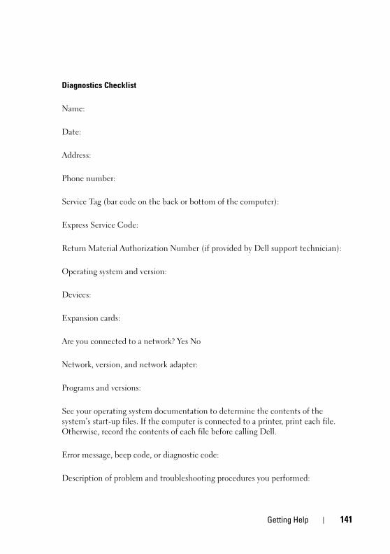
book.book Page 141 Wednesday, April 15, 2009 8:47 PM
Diagnostics Checklist
Name:
Date:
Address:
Phone number:
Service Tag (bar code on the back or bottom of the computer):
Express Service Code:
Return Material Authorization Number (if provided by Dell support technician):
Operating system and version:
Devices:
Expansion cards:
Are you connected to a network? Yes No
Network, version, and network adapter:
Programs and versions:
See your operating system documentation to determine the contents of the system’s start-up files. If the computer is connected to a printer, print each file. Otherwise, record the contents of each file before calling Dell.
Error message, beep code, or diagnostic code:
Description of problem and troubleshooting procedures you performed:
Getting Help 141
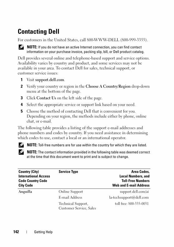
1
book.book Page 142 Wednesday, April 15, 2009 8:47 PM
Contacting DellFor customers in the United States, call 800-WWW-DELL (800-999-3355).
NOTE: If you do not have an active Internet connection, you can find contact
information on your purchase invoice, packing slip, bill, or Dell product catalog.
Dell provides several online and telephone-based support and service options. Availability varies by country and product, and some services may not be available in your area. To contact Dell for sales, technical support, or customer service issues:
1 Visit support.dell.com.
2 Verify your country or region in the Choose A Country/Region drop-down menu at the bottom of the page.
3 Click Contact Us on the left side of the page.
4 Select the appropriate service or support link based on your need.
5 Choose the method of contacting Dell that is convenient for you. Depending on your region, the methods include either by phone, online chat, or e-mail.
The following table provides a listing of the support e-mail addresses and phone numbers and codes by country. If you need assistance in determining which codes to use, contact a local or an international operator.
NOTE: Toll-free numbers are for use within the country for which they are listed.
NOTE: The contact information provided in the following table was deemed correct
at the time that this document went to print and is subject to change.
Country (City)
International Access
Code Country Code
City Code
Service Type Area Codes,
Local Numbers, and
Toll-Free Numbers
Web and E-mail Address
Anguilla Online Support
E-mail Address
support.dell.com/ai
Technical Support, Customer Service, Sales
toll free: 800-335-0031
42 Getting Help
book.book Page 143 Wednesday, April 15, 2009 8:47 PM
Antigua and Barbuda Online Support www.dell.com/ag
Technical Support, Customer Service, Sales
1-800-805-5924
Aomen
Country Code: 853
Technical Support toll-free: 0800-105
Customer Service (Xiamen, China)
34 160 910
Transaction Sales (Xiamen, China)
29 693 115
Argentina (Buenos Aires)
International Access Code: 00
Country Code: 54
City Code: 11
Online Support www.dell.com/ar
E-mail for Desktops and Portables
E-mail for Servers and EMC® Storage Products
Customer Service toll-free: 0-800-666-0789
Technical Support toll-free: 0-800-222-0154
or toll-free: 0-800-444-0724
Sales toll-free: 0-800-666-0789
Aruba Online Support www.dell.com/aw
Technical Support toll-free: 800-1727
Customer Service and Sales
toll-free: 800-1729
Australia (Sydney)
International Access Code: 0011
Country Code: 61
City Code: 2
Online Support
support.ap.dell.com
support.ap.dell.com/contactus
Technical Support
Country (City)
International Access
Code Country Code
City Code
Service Type Area Codes,
Local Numbers, and
Toll-Free Numbers
Web and E-mail Address
Getting Help 143
1
book.book Page 144 Wednesday, April 15, 2009 8:47 PM
Technical Support for XPS computers only
toll-free: 1300 790 877
Home and Home Office toll-free: 1300-655-533
Medium and Large Business
toll-free: 1800-633-559
Small Business, Education, Local Government
toll-free: 1800-060-889
Customer Service
Home and Home Office toll-free: 1800-812-393(option 3)
Medium and Large Business, Education, Local Government
toll-free: 1300-303-270(option 3)
24-Hour Automated Order Status Service
toll-free: 1300-662-196
Austria (Vienna)
International Access Code: 900
Country Code: 43
City Code: 1
NOTE: The phone numbers
in this section should be
called from within Austria
only.
Online Support
support.euro.dell.com
Technical Support for XPS computers only
08 20 24 05 30 81
Large Business Support 08 20 24 05 30 55
Technical Support at Home
08 20 24 05 30 92
Home/Small Business Sales 08 20 24 05 30 00
Home/Small Business Fax 08 20 24 05 30 49
Country (City)
International Access
Code Country Code
City Code
Service Type Area Codes,
Local Numbers, and
Toll-Free Numbers
Web and E-mail Address
44 Getting Help
book.book Page 145 Wednesday, April 15, 2009 8:47 PM
Home/Small Business Customer Service
08 20 24 05 30 14
Home/Small Business Support
08 20 24 05 30 17
Preferred Accounts/Corporate Customer Service
08 20 24 05 30 16
Preferred Accounts/Corporate Support
08 20 24 05 30 17
Switchboard 08 20 24 05 30 00
Bahamas Online Support www.dell.com/bs
Technical Support toll-free: 1-866-874-3038
Customer Service and Sales
toll-free: 1-866-296-9683
Barbados Online Support www.dell.com/bb
Technical Support 1-800-534-3349
Customer Service and Sales
1-800-534-3142
Belgium (Brussels)
International Access Code: 00
Country Code: 32
City Code: 2
Online Support support.euro.dell.com
Technical Support for XPS computers only
02 481 92 96
General Support 02 481 92 88
General Support Fax 02 481 92 95
Customer Service 02 713 15 65
Corporate Sales 02 481 91 00
Fax 02 481 92 99
Switchboard 02 481 91 00
Country (City)
International Access
Code Country Code
City Code
Service Type Area Codes,
Local Numbers, and
Toll-Free Numbers
Web and E-mail Address
Getting Help 145
1
book.book Page 146 Wednesday, April 15, 2009 8:47 PM
Belize Online Support www.dell.com/bz
Technical Support, Customer Service, Sales
811-866-686-9880
or (512) 723-0010
Bermuda Online Support www.dell.com/bm
Technical Support 1-877-890-0754
Customer Service and Sales
1-877-890-0751
Bolivia Online Support www.dell.com/bo
Technical Support, Customer Service, Sales
toll-free: 800-10-0238
or EEUU (512) 723-0010
Brazil
International Access Code: 00
Country Code: 55
City Code: 51
Online Support www.dell.com/br
Technical Support 0800 970 3355
Technical Support Fax 51 2104 5470
Customer Service Fax 51 2104 5480
Sales 0800 970 3390
British Virgin Islands Online Support www.dell.com/vg
Technical Support, Customer Service, Sales
toll-free: 1-866-278-6820
or (512) 723-0010
Country (City)
International Access
Code Country Code
City Code
Service Type Area Codes,
Local Numbers, and
Toll-Free Numbers
Web and E-mail Address
46 Getting Help
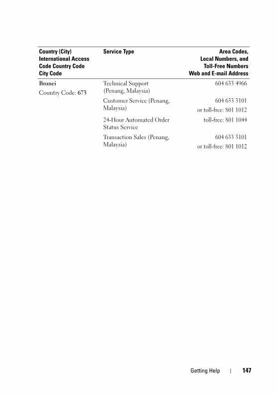
book.book Page 147 Wednesday, April 15, 2009 8:47 PM
Brunei
Country Code: 673
Technical Support (Penang, Malaysia)
604 633 4966
Customer Service (Penang, Malaysia)
604 633 3101
or toll-free: 801 1012
24-Hour Automated Order Status Service
toll-free: 801 1044
Transaction Sales (Penang, Malaysia)
604 633 3101
or toll-free: 801 1012
Country (City)
International Access
Code Country Code
City Code
Service Type Area Codes,
Local Numbers, and
Toll-Free Numbers
Web and E-mail Address
Getting Help 147
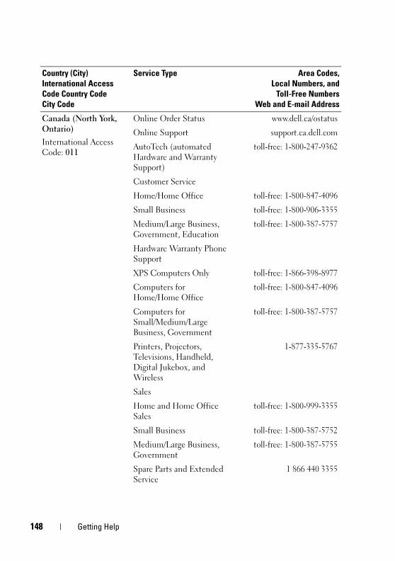
1
book.book Page 148 Wednesday, April 15, 2009 8:47 PM
Canada (North York, Ontario)
International Access Code: 011
Online Order Status www.dell.ca/ostatus
Online Support support.ca.dell.com
AutoTech (automated Hardware and Warranty Support)
toll-free: 1-800-247-9362
Customer Service
Home/Home Office toll-free: 1-800-847-4096
Small Business toll-free: 1-800-906-3355
Medium/Large Business, Government, Education
toll-free: 1-800-387-5757
Hardware Warranty Phone Support
XPS Computers Only toll-free: 1-866-398-8977
Computers for Home/Home Office
toll-free: 1-800-847-4096
Computers for Small/Medium/Large Business, Government
toll-free: 1-800-387-5757
Printers, Projectors, Televisions, Handheld, Digital Jukebox, and Wireless
1-877-335-5767
Sales
Home and Home Office Sales
toll-free: 1-800-999-3355
Small Business toll-free: 1-800-387-5752
Medium/Large Business, Government
toll-free: 1-800-387-5755
Spare Parts and Extended Service
1 866 440 3355
Country (City)
International Access
Code Country Code
City Code
Service Type Area Codes,
Local Numbers, and
Toll-Free Numbers
Web and E-mail Address
48 Getting Help
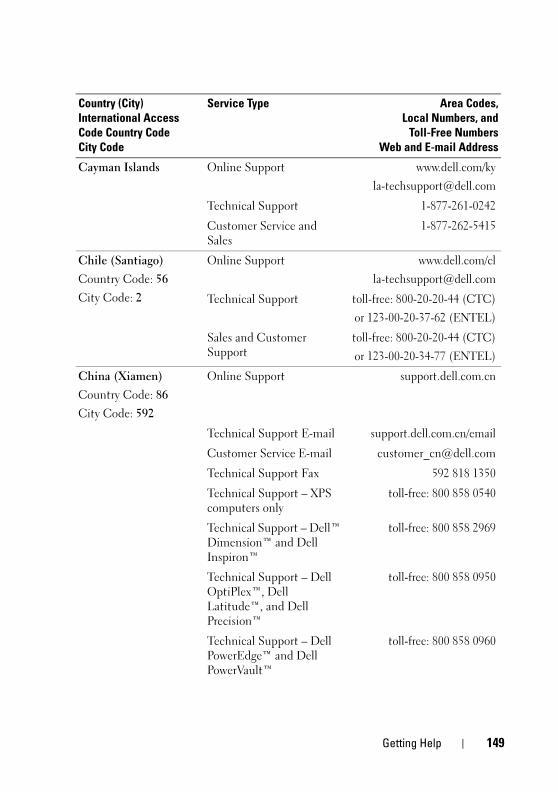
book.book Page 149 Wednesday, April 15, 2009 8:47 PM
Cayman Islands Online Support www.dell.com/ky
Technical Support 1-877-261-0242
Customer Service and Sales
1-877-262-5415
Chile (Santiago)
Country Code: 56
City Code: 2
Online Support www.dell.com/cl
Technical Support toll-free: 800-20-20-44 (CTC)
or 123-00-20-37-62 (ENTEL)
Sales and Customer Support
toll-free: 800-20-20-44 (CTC)
or 123-00-20-34-77 (ENTEL)
China (Xiamen)
Country Code: 86
City Code: 592
Online Support support.dell.com.cn
Technical Support E-mail support.dell.com.cn/email
Customer Service E-mail [email protected]
Technical Support Fax 592 818 1350
Technical Support – XPS computers only
toll-free: 800 858 0540
Technical Support – Dell™ Dimension™ and Dell Inspiron™
toll-free: 800 858 2969
Technical Support – Dell OptiPlex™, Dell Latitude™, and Dell Precision™
toll-free: 800 858 0950
Technical Support – Dell PowerEdge™ and Dell PowerVault™
toll-free: 800 858 0960
Country (City)
International Access
Code Country Code
City Code
Service Type Area Codes,
Local Numbers, and
Toll-Free Numbers
Web and E-mail Address
Getting Help 149
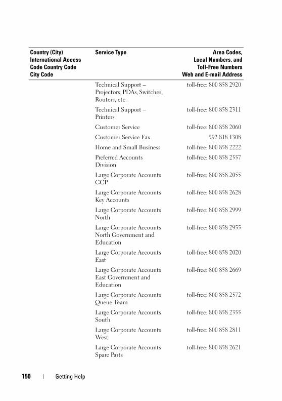
1
book.book Page 150 Wednesday, April 15, 2009 8:47 PM
Technical Support – Projectors, PDAs, Switches, Routers, etc.
toll-free: 800 858 2920
Technical Support – Printers
toll-free: 800 858 2311
Customer Service toll-free: 800 858 2060
Customer Service Fax 592 818 1308
Home and Small Business toll-free: 800 858 2222
Preferred Accounts Division
toll-free: 800 858 2557
Large Corporate Accounts GCP
toll-free: 800 858 2055
Large Corporate Accounts Key Accounts
toll-free: 800 858 2628
Large Corporate Accounts North
toll-free: 800 858 2999
Large Corporate Accounts North Government and Education
toll-free: 800 858 2955
Large Corporate Accounts East
toll-free: 800 858 2020
Large Corporate Accounts East Government and Education
toll-free: 800 858 2669
Large Corporate Accounts Queue Team
toll-free: 800 858 2572
Large Corporate Accounts South
toll-free: 800 858 2355
Large Corporate Accounts West
toll-free: 800 858 2811
Large Corporate Accounts Spare Parts
toll-free: 800 858 2621
Country (City)
International Access
Code Country Code
City Code
Service Type Area Codes,
Local Numbers, and
Toll-Free Numbers
Web and E-mail Address
50 Getting Help
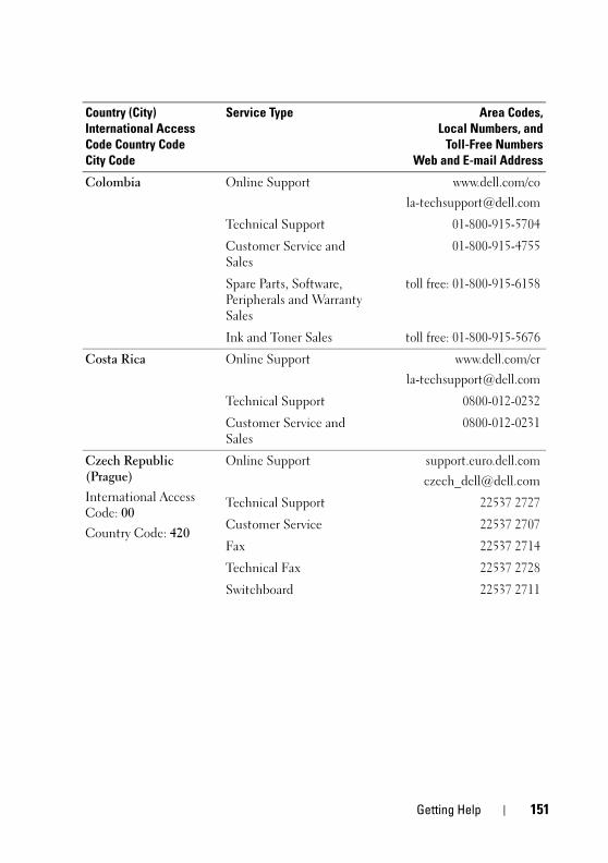
book.book Page 151 Wednesday, April 15, 2009 8:47 PM
Colombia Online Support www.dell.com/co
Technical Support 01-800-915-5704
Customer Service and Sales
01-800-915-4755
Spare Parts, Software, Peripherals and Warranty Sales
toll free: 01-800-915-6158
Ink and Toner Sales toll free: 01-800-915-5676
Costa Rica Online Support www.dell.com/cr
Technical Support 0800-012-0232
Customer Service and Sales
0800-012-0231
Czech Republic (Prague)
International Access Code: 00
Country Code: 420
Online Support support.euro.dell.com
Technical Support 22537 2727
Customer Service 22537 2707
Fax 22537 2714
Technical Fax 22537 2728
Switchboard 22537 2711
Country (City)
International Access
Code Country Code
City Code
Service Type Area Codes,
Local Numbers, and
Toll-Free Numbers
Web and E-mail Address
Getting Help 151
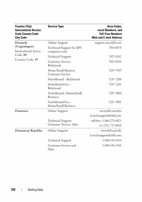
1
book.book Page 152 Wednesday, April 15, 2009 8:47 PM
Denmark (Copenhagen)
International Access Code: 00
Country Code: 45
Online Support support.euro.dell.com
Technical Support for XPS computers only
7010 0074
Technical Support 7023 0182
Customer Service – Relational
7023 0184
Home/Small Business Customer Service
3287 5505
Switchboard – Relational 3287 1200
Switchboard Fax – Relational
3287 1201
Switchboard – Home/Small Business
3287 5000
Switchboard Fax – Home/Small Business
3287 5001
Dominica Online Support www.dell.com/dm
Technical Support, Customer Service, Sales
toll-free: 1-866-278-6821
or (512) 723-0010
Dominican Republic Online Support www.dell.com/do
Technical Support 1-800-156-1834
Customer Service and Sales
1-800-156-1588
Country (City)
International Access
Code Country Code
City Code
Service Type Area Codes,
Local Numbers, and
Toll-Free Numbers
Web and E-mail Address
52 Getting Help
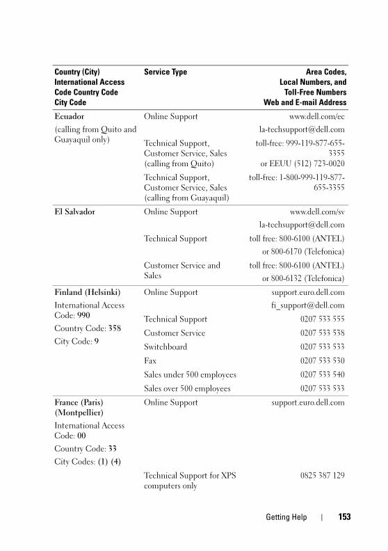
book.book Page 153 Wednesday, April 15, 2009 8:47 PM
Ecuador
(calling from Quito and Guayaquil only)
Online Support www.dell.com/ec
Technical Support, Customer Service, Sales (calling from Quito)
toll-free: 999-119-877-655-3355
or EEUU (512) 723-0020
Technical Support, Customer Service, Sales (calling from Guayaquil)
toll-free: 1-800-999-119-877-655-3355
El Salvador Online Support www.dell.com/sv
Technical Support toll free: 800-6100 (ANTEL)
or 800-6170 (Telefonica)
Customer Service and Sales
toll free: 800-6100 (ANTEL)
or 800-6132 (Telefonica)
Finland (Helsinki)
International Access Code: 990
Country Code: 358
City Code: 9
Online Support support.euro.dell.com
Technical Support 0207 533 555
Customer Service 0207 533 538
Switchboard 0207 533 533
Fax 0207 533 530
Sales under 500 employees 0207 533 540
Sales over 500 employees 0207 533 533
France (Paris) (Montpellier)
International Access Code: 00
Country Code: 33
City Codes: (1) (4)
Online Support support.euro.dell.com
Technical Support for XPS computers only
0825 387 129
Country (City)
International Access
Code Country Code
City Code
Service Type Area Codes,
Local Numbers, and
Toll-Free Numbers
Web and E-mail Address
Getting Help 153
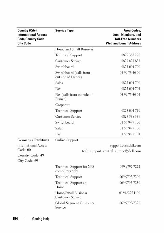
1
book.book Page 154 Wednesday, April 15, 2009 8:47 PM
Home and Small Business
Technical Support 0825 387 270
Customer Service 0825 823 833
Switchboard 0825 004 700
Switchboard (calls from outside of France)
04 99 75 40 00
Sales 0825 004 700
Fax 0825 004 701
Fax (calls from outside of France)
04 99 75 40 01
Corporate
Technical Support 0825 004 719
Customer Service 0825 338 339
Switchboard 01 55 94 71 00
Sales 01 55 94 71 00
Fax 01 55 94 71 01
Germany (Frankfurt)
International Access Code: 00
Country Code: 49
City Code: 69
Online Support
support.euro.dell.com
Technical Support for XPS computers only
069 9792 7222
Technical Support 069 9792-7200
Technical Support at Home
069 9792-7230
Home/Small Business Customer Service
0180-5-224400
Global Segment Customer Service
069 9792-7320
Country (City)
International Access
Code Country Code
City Code
Service Type Area Codes,
Local Numbers, and
Toll-Free Numbers
Web and E-mail Address
54 Getting Help
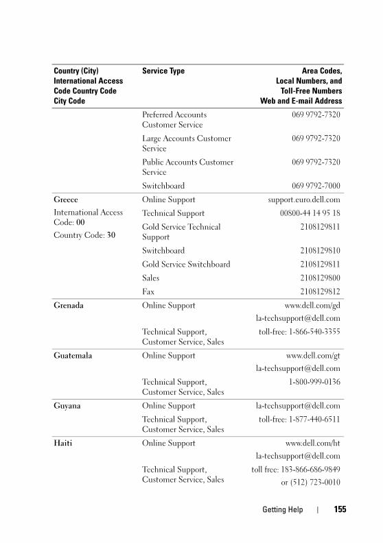
book.book Page 155 Wednesday, April 15, 2009 8:47 PM
Preferred Accounts Customer Service
069 9792-7320
Large Accounts Customer Service
069 9792-7320
Public Accounts Customer Service
069 9792-7320
Switchboard 069 9792-7000
Greece
International Access Code: 00
Country Code: 30
Online Support support.euro.dell.com
Technical Support 00800-44 14 95 18
Gold Service Technical Support
2108129811
Switchboard 2108129810
Gold Service Switchboard 2108129811
Sales 2108129800
Fax 2108129812
Grenada Online Support www.dell.com/gd
Technical Support, Customer Service, Sales
toll-free: 1-866-540-3355
Guatemala Online Support www.dell.com/gt
Technical Support, Customer Service, Sales
1-800-999-0136
Guyana Online Support [email protected]
Technical Support, Customer Service, Sales
toll-free: 1-877-440-6511
Haiti Online Support www.dell.com/ht
Technical Support, Customer Service, Sales
toll free: 183-866-686-9849
or (512) 723-0010
Country (City)
International Access
Code Country Code
City Code
Service Type Area Codes,
Local Numbers, and
Toll-Free Numbers
Web and E-mail Address
Getting Help 155
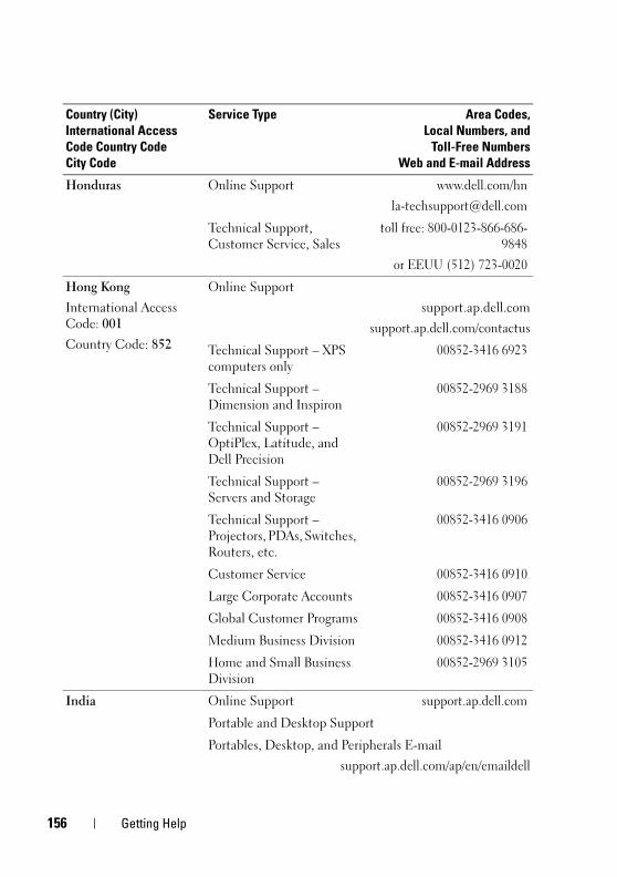
1
book.book Page 156 Wednesday, April 15, 2009 8:47 PM
Honduras Online Support www.dell.com/hn
Technical Support, Customer Service, Sales
toll free: 800-0123-866-686-9848
or EEUU (512) 723-0020
Hong Kong
International Access Code: 001
Country Code: 852
Online Support
support.ap.dell.com
support.ap.dell.com/contactus
Technical Support – XPS computers only
00852-3416 6923
Technical Support – Dimension and Inspiron
00852-2969 3188
Technical Support – OptiPlex, Latitude, and Dell Precision
00852-2969 3191
Technical Support – Servers and Storage
00852-2969 3196
Technical Support – Projectors, PDAs, Switches, Routers, etc.
00852-3416 0906
Customer Service 00852-3416 0910
Large Corporate Accounts 00852-3416 0907
Global Customer Programs 00852-3416 0908
Medium Business Division 00852-3416 0912
Home and Small Business Division
00852-2969 3105
India Online Support support.ap.dell.com
Portable and Desktop Support
Portables, Desktop, and Peripherals E-mail
support.ap.dell.com/ap/en/emaildell
Country (City)
International Access
Code Country Code
City Code
Service Type Area Codes,
Local Numbers, and
Toll-Free Numbers
Web and E-mail Address
56 Getting Help
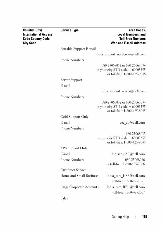
book.book Page 157 Wednesday, April 15, 2009 8:47 PM
Portable Support E-mail
Phone Numbers
080-25068032 or 080-25068034or your city STD code + 60003355
or toll-free: 1-800-425-9046
Server Support
Phone Numbers
080-25068032 or 080-25068034or your city STD code + 60003355
or toll-free: 1-800-425-8045
Gold Support Only
E-mail [email protected]
Phone Numbers
080-25068033or your city STD code + 60003355
or toll-free: 1-800-425-9045
XPS Support Only
E-mail [email protected]
Phone Numbers 080-25068066or toll-free: 1-800-425-2066
Customer Service
Home and Small Business [email protected]
toll-free: 1800-4254051
Large Corporate Accounts [email protected]
toll-free: 1800-4252067
Sales
Country (City)
International Access
Code Country Code
City Code
Service Type Area Codes,
Local Numbers, and
Toll-Free Numbers
Web and E-mail Address
Getting Help 157
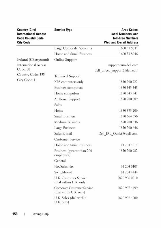
1
book.book Page 158 Wednesday, April 15, 2009 8:47 PM
Large Corporate Accounts 1600 33 8044
Home and Small Business 1600 33 8046
Ireland (Cherrywood)
International Access Code: 00
Country Code: 353
City Code: 1
Online Support
support.euro.dell.com
Technical Support
XPS computers only 1850 200 722
Business computers 1850 543 543
Home computers 1850 543 543
At Home Support 1850 200 889
Sales
Home 1850 333 200
Small Business 1850 664 656
Medium Business 1850 200 646
Large Business 1850 200 646
Sales E-mail [email protected]
Customer Service
Home and Small Business 01 204 4014
Business (greater than 200 employees)
1850 200 982
General
Fax/Sales Fax 01 204 0103
Switchboard 01 204 4444
U.K. Customer Service (dial within U.K. only)
0870 906 0010
Corporate Customer Service (dial within U.K. only)
0870 907 4499
U.K. Sales (dial within U.K. only)
0870 907 4000
Country (City)
International Access
Code Country Code
City Code
Service Type Area Codes,
Local Numbers, and
Toll-Free Numbers
Web and E-mail Address
58 Getting Help
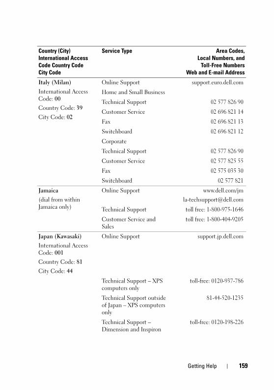
book.book Page 159 Wednesday, April 15, 2009 8:47 PM
Italy (Milan)
International Access Code: 00
Country Code: 39
City Code: 02
Online Support support.euro.dell.com
Home and Small Business
Technical Support 02 577 826 90
Customer Service 02 696 821 14
Fax 02 696 821 13
Switchboard 02 696 821 12
Corporate
Technical Support 02 577 826 90
Customer Service 02 577 825 55
Fax 02 575 035 30
Switchboard 02 577 821
Jamaica
(dial from within Jamaica only)
Online Support www.dell.com/jm
Technical Support toll free: 1-800-975-1646
Customer Service and Sales
toll free: 1-800-404-9205
Japan (Kawasaki)
International Access Code: 001
Country Code: 81
City Code: 44
Online Support support.jp.dell.com
Technical Support – XPS computers only
toll-free: 0120-937-786
Technical Support outside of Japan – XPS computers only
81-44-520-1235
Technical Support – Dimension and Inspiron
toll-free: 0120-198-226
Country (City)
International Access
Code Country Code
City Code
Service Type Area Codes,
Local Numbers, and
Toll-Free Numbers
Web and E-mail Address
Getting Help 159
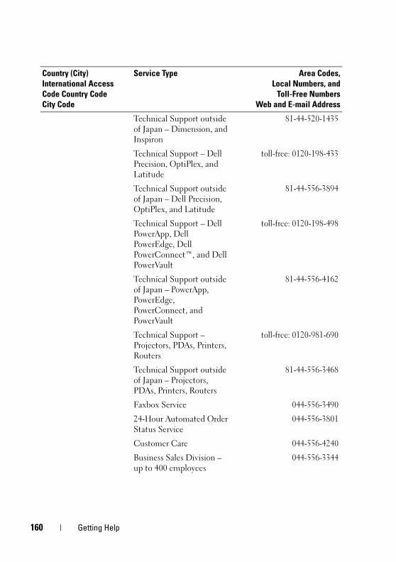
1
book.book Page 160 Wednesday, April 15, 2009 8:47 PM
Technical Support outside of Japan – Dimension, and Inspiron
81-44-520-1435
Technical Support – Dell Precision, OptiPlex, and Latitude
toll-free: 0120-198-433
Technical Support outside of Japan – Dell Precision, OptiPlex, and Latitude
81-44-556-3894
Technical Support – Dell PowerApp, Dell PowerEdge, Dell PowerConnect™, and Dell PowerVault
toll-free: 0120-198-498
Technical Support outside of Japan – PowerApp, PowerEdge, PowerConnect, and PowerVault
81-44-556-4162
Technical Support – Projectors, PDAs, Printers, Routers
toll-free: 0120-981-690
Technical Support outside of Japan – Projectors, PDAs, Printers, Routers
81-44-556-3468
Faxbox Service 044-556-3490
24-Hour Automated Order Status Service
044-556-3801
Customer Care 044-556-4240
Business Sales Division – up to 400 employees
044-556-3344
Country (City)
International Access
Code Country Code
City Code
Service Type Area Codes,
Local Numbers, and
Toll-Free Numbers
Web and E-mail Address
60 Getting Help
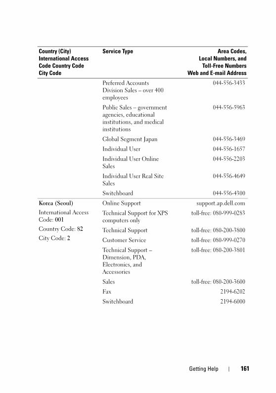
book.book Page 161 Wednesday, April 15, 2009 8:47 PM
Preferred Accounts Division Sales – over 400 employees
044-556-3433
Public Sales – government agencies, educational institutions, and medical institutions
044-556-5963
Global Segment Japan 044-556-3469
Individual User 044-556-1657
Individual User Online Sales
044-556-2203
Individual User Real Site Sales
044-556-4649
Switchboard 044-556-4300
Korea (Seoul)
International Access Code: 001
Country Code: 82
City Code: 2
Online Support support.ap.dell.com
Technical Support for XPS computers only
toll-free: 080-999-0283
Technical Support toll-free: 080-200-3800
Customer Service toll-free: 080-999-0270
Technical Support – Dimension, PDA, Electronics, and Accessories
toll-free: 080-200-3801
Sales toll-free: 080-200-3600
Fax 2194-6202
Switchboard 2194-6000
Country (City)
International Access
Code Country Code
City Code
Service Type Area Codes,
Local Numbers, and
Toll-Free Numbers
Web and E-mail Address
Getting Help 161
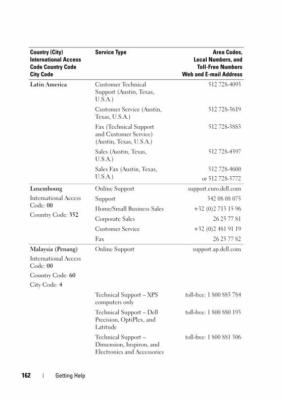
1
book.book Page 162 Wednesday, April 15, 2009 8:47 PM
Latin America Customer Technical Support (Austin, Texas, U.S.A.)
512 728-4093
Customer Service (Austin, Texas, U.S.A.)
512 728-3619
Fax (Technical Support and Customer Service) (Austin, Texas, U.S.A.)
512 728-3883
Sales (Austin, Texas, U.S.A.)
512 728-4397
Sales Fax (Austin, Texas, U.S.A.)
512 728-4600
or 512 728-3772
Luxembourg
International Access Code: 00
Country Code: 352
Online Support support.euro.dell.com
Support 342 08 08 075
Home/Small Business Sales +32 (0)2 713 15 96
Corporate Sales 26 25 77 81
Customer Service +32 (0)2 481 91 19
Fax 26 25 77 82
Malaysia (Penang)
International Access Code: 00
Country Code: 60
City Code: 4
Online Support support.ap.dell.com
Technical Support – XPS computers only
toll-free: 1 800 885 784
Technical Support – Dell Precision, OptiPlex, and Latitude
toll-free: 1 800 880 193
Technical Support – Dimension, Inspiron, and Electronics and Accessories
toll-free: 1 800 881 306
Country (City)
International Access
Code Country Code
City Code
Service Type Area Codes,
Local Numbers, and
Toll-Free Numbers
Web and E-mail Address
62 Getting Help
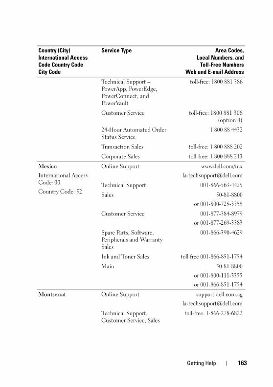
book.book Page 163 Wednesday, April 15, 2009 8:47 PM
Technical Support – PowerApp, PowerEdge, PowerConnect, and PowerVault
toll-free: 1800 881 386
Customer Service toll-free: 1800 881 306(option 4)
24-Hour Automated Order Status Service
1 800 88 4432
Transaction Sales toll-free: 1 800 888 202
Corporate Sales toll-free: 1 800 888 213
Mexico
International Access Code: 00
Country Code: 52
Online Support www.dell.com/mx
Technical Support 001-866-563-4425
Sales 50-81-8800
or 001-800-725-3355
Customer Service 001-877-384-8979
or 001-877-269-3383
Spare Parts, Software, Peripherals and Warranty Sales
001-866-390-4629
Ink and Toner Sales toll free 001-866-851-1754
Main 50-81-8800
or 001-800-111-3355
or 001-866-851-1754
Montserrat Online Support support.dell.com.ag
Technical Support, Customer Service, Sales
toll-free: 1-866-278-6822
Country (City)
International Access
Code Country Code
City Code
Service Type Area Codes,
Local Numbers, and
Toll-Free Numbers
Web and E-mail Address
Getting Help 163
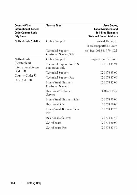
1
book.book Page 164 Wednesday, April 15, 2009 8:47 PM
Netherlands Antilles Online Support www.dell.com/an
Technical Support, Customer Service, Sales
toll free: 001-866-379-1022
Netherlands (Amsterdam)
International Access Code: 00
Country Code: 31
City Code: 20
Online Support support.euro.dell.com
Technical Support for XPS computers only
020 674 45 94
Technical Support 020 674 45 00
Technical Support Fax 020 674 47 66
Home/Small Business Customer Service
020 674 42 00
Relational Customer Service
020 674 4325
Home/Small Business Sales 020 674 55 00
Relational Sales 020 674 50 00
Home/Small Business Sales Fax
020 674 47 75
Relational Sales Fax 020 674 47 50
Switchboard 020 674 50 00
Switchboard Fax 020 674 47 50
Country (City)
International Access
Code Country Code
City Code
Service Type Area Codes,
Local Numbers, and
Toll-Free Numbers
Web and E-mail Address
64 Getting Help
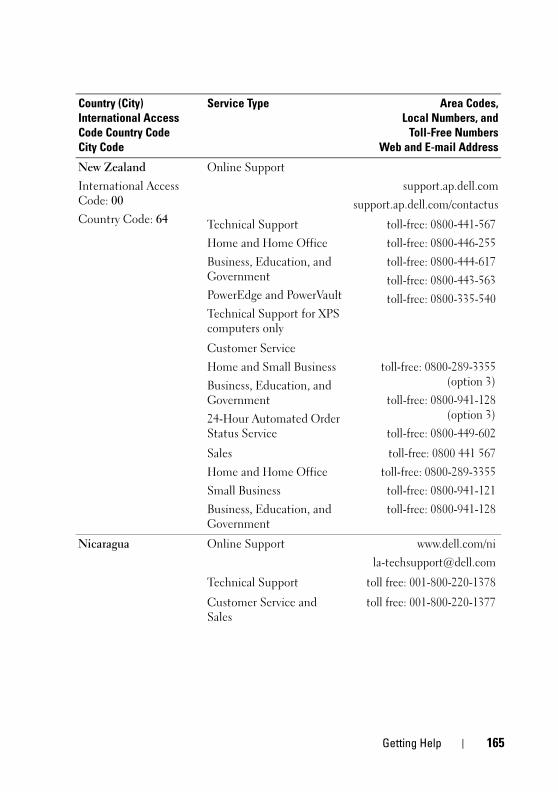
book.book Page 165 Wednesday, April 15, 2009 8:47 PM
New Zealand
International Access Code: 00
Country Code: 64
Online Support
support.ap.dell.com
support.ap.dell.com/contactus
Technical Support
Home and Home Office
Business, Education, and Government
PowerEdge and PowerVault
Technical Support for XPS computers only
toll-free: 0800-441-567
toll-free: 0800-446-255
toll-free: 0800-444-617
toll-free: 0800-443-563
toll-free: 0800-335-540
Customer Service
Home and Small Business
Business, Education, and Government
24-Hour Automated Order Status Service
toll-free: 0800-289-3355(option 3)
toll-free: 0800-941-128(option 3)
toll-free: 0800-449-602
Sales
Home and Home Office
Small Business
Business, Education, and Government
toll-free: 0800 441 567
toll-free: 0800-289-3355
toll-free: 0800-941-121
toll-free: 0800-941-128
Nicaragua Online Support www.dell.com/ni
Technical Support toll free: 001-800-220-1378
Customer Service and Sales
toll free: 001-800-220-1377
Country (City)
International Access
Code Country Code
City Code
Service Type Area Codes,
Local Numbers, and
Toll-Free Numbers
Web and E-mail Address
Getting Help 165
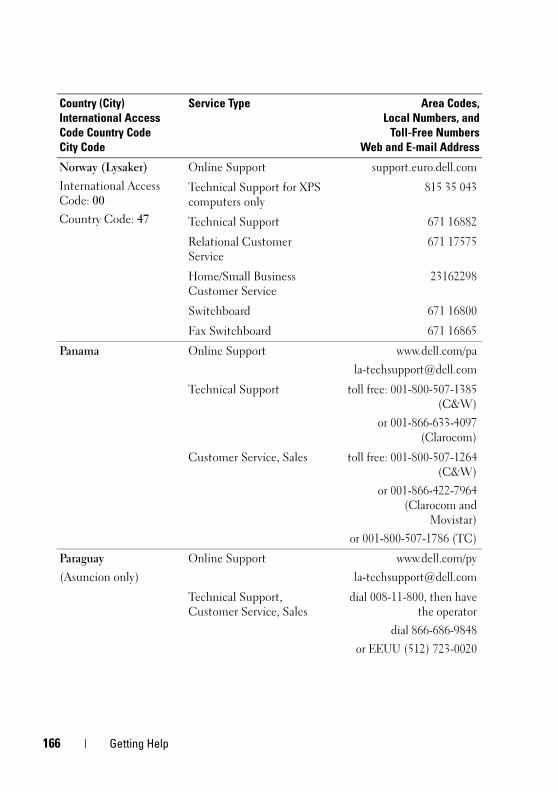
1
book.book Page 166 Wednesday, April 15, 2009 8:47 PM
Norway (Lysaker)
International Access Code: 00
Country Code: 47
Online Support support.euro.dell.com
Technical Support for XPS computers only
815 35 043
Technical Support 671 16882
Relational Customer Service
671 17575
Home/Small Business Customer Service
23162298
Switchboard 671 16800
Fax Switchboard 671 16865
Panama Online Support www.dell.com/pa
Technical Support toll free: 001-800-507-1385(C&W)
or 001-866-633-4097(Clarocom)
Customer Service, Sales toll free: 001-800-507-1264(C&W)
or 001-866-422-7964(Clarocom and
Movistar)
or 001-800-507-1786 (TC)
Paraguay
(Asuncion only)
Online Support www.dell.com/py
Technical Support, Customer Service, Sales
dial 008-11-800, then havethe operator
dial 866-686-9848
or EEUU (512) 723-0020
Country (City)
International Access
Code Country Code
City Code
Service Type Area Codes,
Local Numbers, and
Toll-Free Numbers
Web and E-mail Address
66 Getting Help
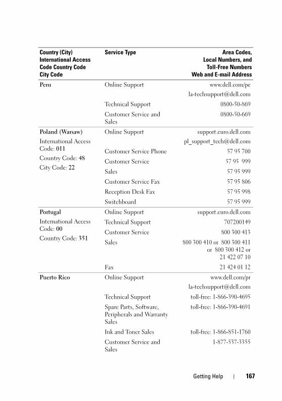
book.book Page 167 Wednesday, April 15, 2009 8:47 PM
Peru Online Support www.dell.com/pe
Technical Support 0800-50-869
Customer Service and Sales
0800-50-669
Poland (Warsaw)
International Access Code: 011
Country Code: 48
City Code: 22
Online Support support.euro.dell.com
Customer Service Phone 57 95 700
Customer Service 57 95 999
Sales 57 95 999
Customer Service Fax 57 95 806
Reception Desk Fax 57 95 998
Switchboard 57 95 999
Portugal
International Access Code: 00
Country Code: 351
Online Support support.euro.dell.com
Technical Support 707200149
Customer Service 800 300 413
Sales 800 300 410 or 800 300 411or 800 300 412 or
21 422 07 10
Fax 21 424 01 12
Puerto Rico Online Support www.dell.com/pr
Technical Support toll-free: 1-866-390-4695
Spare Parts, Software, Peripherals and Warranty Sales
toll-free: 1-866-390-4691
Ink and Toner Sales toll-free: 1-866-851-1760
Customer Service and Sales
1-877-537-3355
Country (City)
International Access
Code Country Code
City Code
Service Type Area Codes,
Local Numbers, and
Toll-Free Numbers
Web and E-mail Address
Getting Help 167
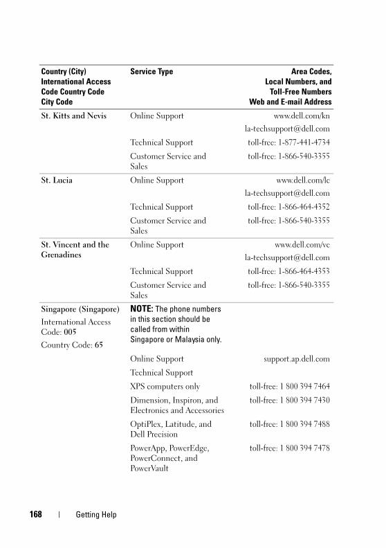
1
book.book Page 168 Wednesday, April 15, 2009 8:47 PM
St. Kitts and Nevis Online Support www.dell.com/kn
Technical Support toll-free: 1-877-441-4734
Customer Service and Sales
toll-free: 1-866-540-3355
St. Lucia Online Support www.dell.com/lc
Technical Support toll-free: 1-866-464-4352
Customer Service and Sales
toll-free: 1-866-540-3355
St. Vincent and the Grenadines
Online Support www.dell.com/vc
Technical Support toll-free: 1-866-464-4353
Customer Service and Sales
toll-free: 1-866-540-3355
Singapore (Singapore)
International Access Code: 005
Country Code: 65
NOTE: The phone numbers
in this section should be
called from within
Singapore or Malaysia only.
Online Support support.ap.dell.com
Technical Support
XPS computers only toll-free: 1 800 394 7464
Dimension, Inspiron, and Electronics and Accessories
toll-free: 1 800 394 7430
OptiPlex, Latitude, and Dell Precision
toll-free: 1 800 394 7488
PowerApp, PowerEdge, PowerConnect, and PowerVault
toll-free: 1 800 394 7478
Country (City)
International Access
Code Country Code
City Code
Service Type Area Codes,
Local Numbers, and
Toll-Free Numbers
Web and E-mail Address
68 Getting Help
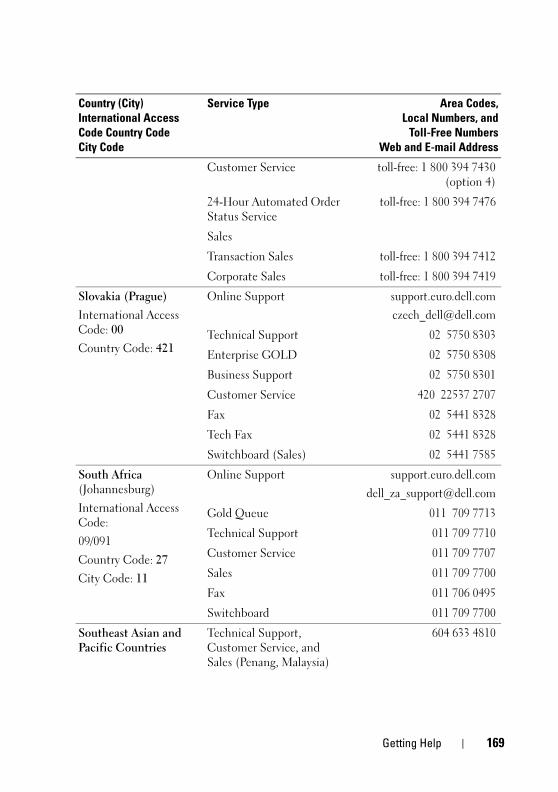
book.book Page 169 Wednesday, April 15, 2009 8:47 PM
Customer Service toll-free: 1 800 394 7430(option 4)
24-Hour Automated Order Status Service
toll-free: 1 800 394 7476
Sales
Transaction Sales toll-free: 1 800 394 7412
Corporate Sales toll-free: 1 800 394 7419
Slovakia (Prague)
International Access Code: 00
Country Code: 421
Online Support support.euro.dell.com
Technical Support 02 5750 8303
Enterprise GOLD 02 5750 8308
Business Support 02 5750 8301
Customer Service 420 22537 2707
Fax 02 5441 8328
Tech Fax 02 5441 8328
Switchboard (Sales) 02 5441 7585
South Africa (Johannesburg)
International Access Code:
09/091
Country Code: 27
City Code: 11
Online Support support.euro.dell.com
Gold Queue 011 709 7713
Technical Support 011 709 7710
Customer Service 011 709 7707
Sales 011 709 7700
Fax 011 706 0495
Switchboard 011 709 7700
Southeast Asian and Pacific Countries
Technical Support, Customer Service, and Sales (Penang, Malaysia)
604 633 4810
Country (City)
International Access
Code Country Code
City Code
Service Type Area Codes,
Local Numbers, and
Toll-Free Numbers
Web and E-mail Address
Getting Help 169
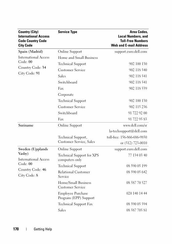
1
book.book Page 170 Wednesday, April 15, 2009 8:47 PM
Spain (Madrid)
International Access Code: 00
Country Code: 34
City Code: 91
Online Support support.euro.dell.com
Home and Small Business
Technical Support 902 100 130
Customer Service 902 118 540
Sales 902 118 541
Switchboard 902 118 541
Fax 902 118 539
Corporate
Technical Support 902 100 130
Customer Service 902 115 236
Switchboard 91 722 92 00
Fax 91 722 95 83
Suriname Online Support www.dell.com/sr
Technical Support, Customer Service, Sales
toll-free: 156-866-686-9850
or (512) 723-0010
Sweden (Upplands Vasby)
International Access Code: 00
Country Code: 46
City Code: 8
Online Support support.euro.dell.com
Technical Support for XPS computers only
77 134 03 40
Technical Support 08 590 05 199
Relational Customer Service
08 590 05 642
Home/Small Business Customer Service
08 587 70 527
Employee Purchase Program (EPP) Support
020 140 14 44
Technical Support Fax 08 590 05 594
Sales 08 587 705 81
Country (City)
International Access
Code Country Code
City Code
Service Type Area Codes,
Local Numbers, and
Toll-Free Numbers
Web and E-mail Address
70 Getting Help
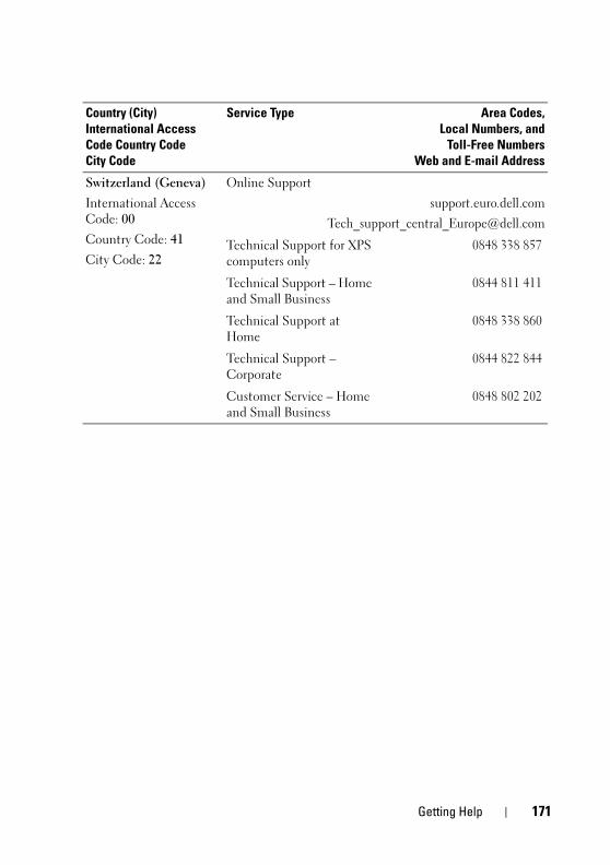
book.book Page 171 Wednesday, April 15, 2009 8:47 PM
Switzerland (Geneva)
International Access Code: 00
Country Code: 41
City Code: 22
Online Support
support.euro.dell.com
Technical Support for XPS computers only
0848 338 857
Technical Support – Home and Small Business
0844 811 411
Technical Support at Home
0848 338 860
Technical Support – Corporate
0844 822 844
Customer Service – Home and Small Business
0848 802 202
Country (City)
International Access
Code Country Code
City Code
Service Type Area Codes,
Local Numbers, and
Toll-Free Numbers
Web and E-mail Address
Getting Help 171

1
book.book Page 172 Wednesday, April 15, 2009 8:47 PM
72 Getting Help
book.book Page 173 Wednesday, April 15, 2009 8:47 PM
Glossary
This section defines or identifies technical terms, abbreviations, and acronyms used in your system documents.
A — Ampere(s).
AC — Alternating current.
ACPI — Advanced Configuration and Power Interface. A standard interface for enabling the operating system to direct configuration and power management.
ambient temperature — The temperature of the area or room where the system is located.
ANSI — American National Standards Institute. The primary organization for developing technology standards in the U.S.
application — Software designed to help you perform a specific task or series of tasks. Applications run from the operating system.
ASCII — American Standard Code for Information Interchange.
asset tag — An individual code assigned to a system, usually by an administrator, for security or tracking purposes.
backup — A copy of a program or data file. As a precaution, back up your system’s hard drive on a regular basis. Before making a change to the configuration of your system, back up important start-up files from your operating system.
backup battery — A battery that maintains system configuration, date, and time information in a special section of memory when the system is turned off.
beep code — A diagnostic message in the form of a pattern of beeps from your system’s speaker. For example, one beep, followed by a second beep, and then a burst of three beeps is beep code 1-1-3.
BIOS — Basic input/output system. Your system’s BIOS contains programs stored on a flash memory chip. The BIOS controls the following:
• Communications between the processor and peripheral devices
• Miscellaneous functions, such as system messages
bit — The smallest unit of information interpreted by your system.
blade — A module that contains a processor, memory, and a hard drive. The modules are mounted into a chassis that includes power supplies and fans.
BMC — Baseboard management controller.
Glossary 173
1
book.book Page 174 Wednesday, April 15, 2009 8:47 PM
boot routine — A program that clears all memory, initializes devices, and loads the operating system when you start your system. Unless the operating system fails to respond, you can reboot (also called warm boot) your system by pressing <Ctrl><Alt><Del>. Otherwise, you must restart the system by pressing the reset button or by turning the system off and then back on.
bootable diskette — A diskette that is used to start your system if the system will not boot from the hard drive.
BTU — British thermal unit.
bus — An information pathway between the components of a system. Your system contains an expansion bus that allows the processor to communicate with controllers for the peripheral devices connected to the system. Your system also contains an address bus and a data bus for communications between the processor and RAM.
C — Celsius.
cache — A fast storage area that keeps a copy of data or instructions for quick data retrieval. When a program makes a request to a disk drive for data that is in the cache, the disk-cache utility can retrieve the data from RAM faster than from the disk drive.
CD — Compact disc. CD drives use optical technology to read data from CDs.
cm — Centimeter(s).
cmos — Complementary metal-oxide semiconductor.
component — As they relate to DMI, components include operating systems, computer systems, expansion cards, and peripherals that are compatible with DMI. Each component is made up of groups and attributes that are defined as relevant to that component.
COMn — The device names for the serial ports on your system.
control panel — The part of the system that contains indicators and controls, such as the power button and power indicator.
controller — A chip that controls the transfer of data between the processor and memory or between the processor and a peripheral.
conventional memory — The first 640 KB of RAM. Conventional memory is found in all systems. Unless they are specially designed, MS-DOS® programs are limited to running in conventional memory.
coprocessor — A chip that relieves the system’s processor of specific processing tasks. A math coprocessor, for example, handles numeric processing.
CPU — Central processing unit. See processor.
DC — Direct current.
74 Glossary

book.book Page 175 Wednesday, April 15, 2009 8:47 PM
DDR — Double-data rate. A technology in memory modules that potentially doubles the output.
device driver — A program that allows the operating system or some other program to interface correctly with a peripheral. Some device drivers—such as network drivers—must be loaded from the config.sys file or as memory-resident programs (usually, from the autoexec.bat file). Others must load when you start the program for which they were designed.
DHCP — Dynamic Host Configuration Protocol. A method of automatically assigning an IP address to a client system.
diagnostics — A comprehensive set of tests for your system.
DIMM — Dual in-line memory module. See also memory module.
DIN — Deutsche Industrie Norm.
directory — Directories help keep related files organized on a disk in a hierarchical, “inverted tree” structure. Each disk has a “root” directory. Additional directories that branch off the root directory are called subdirectories. Subdirectories may contain additional directories branching off them.
DMA — Direct memory access. A DMA channel allows certain types of data transfer between RAM and a device to bypass the processor.
DMI — Desktop Management Interface. DMI enables the management of your system’s software and hardware by collecting information about the system’s components, such as the operating system, memory, peripherals, expansion cards, and asset tag.
DNS — Domain Name System. A method of translating Internet domain names, such as www.dell.com, into IP addresses, such as 143.166.83.200.
DRAM — Dynamic random-access memory. A system’s RAM is usually made up entirely of DRAM chips.
DVD — Digital versatile disc.
ECC — Error checking and correction.
EEPROM — Electronically erasable programmable read-only memory.
EMC — Electromagnetic compatibility.
EMI — Electromagnetic interference.
ERA — Embedded remote access. ERA allows you to perform remote, or "out-of-band," server management on your network server using a remote access controller.
ESD — Electrostatic discharge.
ESM — Embedded server management.
Glossary 175
1
book.book Page 176 Wednesday, April 15, 2009 8:47 PM
expansion bus — Your system contains an expansion bus that allows the processor to communicate with controllers for peripherals, such as NICs.
expansion card — An add-in card, such as a NIC or SCSI adapter, that plugs into an expansion-card connector on the system board. An expansion card adds some specialized function to the system by providing an interface between the expansion bus and a peripheral.
expansion-card connector — A connector on the system board or riser board for plugging in an expansion card.
F — Fahrenheit.
FAT — File allocation table. The file system structure used by MS-DOS to organize and keep track of file storage. The Microsoft® Windows® operating systems can optionally use a FAT file system structure.
flash memory — A type of EEPROM chip that can be reprogrammed from a utility on diskette while still installed in a system; most EEPROM chips can only be rewritten with special programming equipment.
format — To prepare a hard drive or diskette for storing files. An unconditional format deletes all data stored on the disk.
FSB — Front-side bus. The FSB is the data path and physical interface between the processor and the main memory (RAM).
ft — Feet.
FTP — File transfer protocol.
g — Gram(s).
G — Gravities.
Gb — Gigabit(s); 1024 megabits or 1,073,741,824 bits.
GB — Gigabyte(s); 1024 megabytes or 1,073,741,824 bytes. However, when referring to hard-drive capacity, the term is usually rounded to 1,000,000,000 bytes.
graphics mode — A video mode that can be defined as x horizontal by y vertical pixels by z colors.
group — As it relates to DMI, a group is a data structure that defines common information, or attributes, about a manageable component.
guarding — A type of data redundancy in which a set of physical drives stores data and an additional drive stores parity data. See also mirroring, striping, and RAID.
h — Hexadecimal. A base-16 numbering system, often used in programming to identify addresses in the system’s RAM and I/O memory addresses for devices. In text, hexadecimal numbers are often followed by h.
76 Glossary
book.book Page 177 Wednesday, April 15, 2009 8:47 PM
headless system — A system or device that functions without having a keyboard, mouse, or monitor attached. Normally, headless systems are managed over a network using an Internet browser.
host adapter — A host adapter implements communication between the system’s bus and the controller for a peripheral device. (Hard-drive controller subsystems include integrated host adapter circuitry.) To add a SCSI expansion bus to your system, you must install or connect the appropriate host adapter.
Hz — Hertz.
I/O — Input/output. A keyboard is an input device, and a monitor is an output device. In general, I/O activity can be differentiated from computational activity.
ID — Identification.
IDE — Integrated drive electronics. A standard interface between the system board and storage devices.
integrated mirroring — Provides simultaneous physical mirroring of two drives. Integrated mirroring functionality is provided by the system’s hardware. See also mirroring.
internal processor cache — An instruction and data cache built into the processor.
IP — Internet Protocol.
IPX — Internet package exchange.
IRQ — Interrupt request. A signal that data is about to be sent to or received by a peripheral device travels by an IRQ line to the processor. Each peripheral connection must be assigned an IRQ number. Two devices can share the same IRQ assignment, but you cannot operate both devices simultaneously.
jumper — Small blocks on a circuit board with two or more pins emerging from them. Plastic plugs containing a wire fit down over the pins. The wire connects the pins and creates a circuit, providing a simple and reversible method of changing the circuitry in a board.
K — Kilo-; 1000.
Kb — Kilobit(s); 1024 bits.
KB — Kilobyte(s); 1024 bytes.
Kbps — Kilobit(s) per second.
KBps — Kilobyte(s) per second.
key combination — A command requiring you to press multiple keys at the same time (for example, <Ctrl><Alt><Del>).
kg — Kilogram(s); 1000 grams.
Glossary 177
1
book.book Page 178 Wednesday, April 15, 2009 8:47 PM
kHz — Kilohertz.
KMM — Keyboard/monitor/mouse.
KVM — Keyboard/video/mouse. KVM refers to a switch that allows selection of the system from which the video is displayed and for which the keyboard and mouse are used.
LAN — Local area network. A LAN is usually confined to the same building or a few nearby buildings, with all equipment linked by wiring dedicated specifically to the LAN.
lb — Pound(s).
LCD — Liquid crystal display.
LED — Light-emitting diode. An electronic device that lights up when a current is passed through it.
Linux — An operating system similar to the UNIX® operating system that runs on a variety of hardware systems. Linux is open source software, which is freely available; however, the full distribution of Linux along with technical support and training are available for a fee from vendors such as Red Hat® Software.
local bus — On a system with local-bus expansion capability, certain peripheral devices (such as the video adapter circuitry) can be designed to run much faster than they would with a traditional expansion bus. See also bus.
LVD — Low voltage differential.
m — Meter(s).
mA — Milliampere(s).
MAC address — Media Access Control address. Your system’s unique hardware number on a network.
mAh — Milliampere-hour(s).
Mb — Megabit(s); 1,048,576 bits.
MB — Megabyte(s); 1,048,576 bytes. However, when referring to hard-drive capacity, the term is often rounded to mean 1,000,000 bytes.
Mbps — Megabits per second.
MBps — Megabytes per second.
MBR — Master boot record.
memory address — A specific location, usually expressed as a hexadecimal number, in the system’s RAM.
memory module — A small circuit board containing DRAM chips that connects to the system board.
78 Glossary
book.book Page 179 Wednesday, April 15, 2009 8:47 PM
memory — An area in your system that stores basic system data. A system can contain several different forms of memory, such as integrated memory (ROM and RAM) and add-in memory modules (DIMMs).
MHz — Megahertz.
mirroring — A type of data redundancy in which a set of physical drives stores data and one or more sets of additional drives stores duplicate copies of the data. Mirroring functionality is provided by software. See also guarding, integrated mirroring, striping, and RAID.
mm — Millimeter(s).
ms — Millisecond(s).
MS-DOS® — Microsoft Disk Operating System.
NAS — Network Attached Storage. NAS is one of the concepts used for implementing shared storage on a network. NAS systems have their own operating systems, integrated hardware, and software that are optimized to serve specific storage needs.
NIC — Network interface controller. A device that is installed or integrated in a system to allow connection to a network.
NMI — Nonmaskable interrupt. A device sends an NMI to signal the processor about hardware errors.
ns — Nanosecond(s).
NTFS — The NT File System option in the Windows 2000 operating system.
NVRAM — Nonvolatile random-access memory. Memory that does not lose its contents when you turn off your system. NVRAM is used for maintaining the date, time, and system configuration information.
parity — Redundant information that is associated with a block of data.
partition — You can divide a hard drive into multiple physical sections called partitions with the fdisk command. Each partition can contain multiple logical drives. You must format each logical drive with the format command.
PCI — Peripheral Component Interconnect. A standard for local-bus implementation.
PDU — Power distribution unit. A power source with multiple power outlets that provides electrical power to servers and storage systems in a rack.
peripheral — An internal or external device, such as a diskette drive or keyboard, connected to a system.
PGA — Pin grid array. A type of processor socket that allows you to remove the processor chip.
Glossary 179
1
book.book Page 180 Wednesday, April 15, 2009 8:47 PM
pixel — A single point on a video display. Pixels are arranged in rows and columns to create an image. A video resolution, such as 640 x 480, is expressed as the number of pixels across by the number of pixels up and down.
POST — Power-on self-test. Before the operating system loads when you turn on your system, the POST tests various system components such as RAM and hard drives.
processor — The primary computational chip inside the system that controls the interpretation and execution of arithmetic and logic functions. Software written for one processor must usually be revised to run on another processor. CPU is a synonym for processor.
protected mode — An operating mode that allows operating systems to implement:
• A memory address space of 16 MB to 4 GB
• Multitasking
• Virtual memory, a method for increasing addressable memory by using the hard drive
The Windows 2000 and UNIX 32-bit operating systems run in protected mode. MS-DOS cannot run in protected mode.
PS/2 — Personal System/2.
PXE — Preboot eXecution Environment. A way of booting a system via a LAN (without a hard drive or bootable diskette).
RAC — Remote access controller.
RAID — Redundant array of independent disks. A method of providing data redundancy. Some common implementations of RAID include RAID 0, RAID 1, RAID 5, RAID 10, and RAID 50. See also guarding, mirroring, and striping.
RAM — Random-access memory. The system’s primary temporary storage area for program instructions and data. Any information stored in RAM is lost when you turn off your system.
RAS — Remote Access Service. This service allows users running the Windows operating system to remotely access a network from their system using a modem.
readme file — A text file, usually shipped with software or hardware, that contains information supplementing or updating the product’s documentation.
read-only file — A read-only file is one that you are prohibited from editing or deleting.
ROM — Read-only memory. Your system contains some programs essential to its operation in ROM code. A ROM chip retains its contents even after you turn off your system. Examples of code in ROM include the program that initiates your system’s boot routine and the POST.
ROMB — RAID on motherboard.
80 Glossary
book.book Page 181 Wednesday, April 15, 2009 8:47 PM
rpm — Revolutions per minute.
RTC — Real-time clock.
SAS — Serial-attached SCSI.
SATA — Serial Advanced Technology Attachment. A standard interface between the system board and storage devices.
SCSI — Small computer system interface. An I/O bus interface with faster data transmission rates than standard ports.
SDRAM — Synchronous dynamic random-access memory.
sec — Second(s).
serial port — An I/O port used most often to connect a modem to your system. You can usually identify a serial port on your system by its 9-pin connector.
service tag — A bar code label on the system used to identify it when you call Dell for technical support.
simple disk volume — The volume of free space on a single dynamic, physical disk.
SMART — Self-Monitoring Analysis and Reporting Technology. Allows hard drives to report errors and failures to the system BIOS and then display an error message on the screen.
SMP — Symmetric multiprocessing. Used to describe a system that has two or more processors connected via a high-bandwidth link and managed by an operating system, where each processor has equal access to I/O devices.
SNMP — Simple Network Management Protocol. A standard interface that allows a network manager to remotely monitor and manage workstations.
spanning — Spanning, or concatenating, disk volumes combines unallocated space from multiple disks into one logical volume, allowing more efficient use of all the space and all drive letters on a multiple-disk system.
striping — Disk striping writes data across three or more disks in an array, but only uses a portion of the space on each disk. The amount of space used by a "stripe" is the same on each disk used. A virtual disk may use several stripes on the same set of disks in an array. See also guarding, mirroring, and RAID.
SVGA — Super video graphics array. VGA and SVGA are video standards for video adapters with greater resolution and color display capabilities than previous standards.
system board — As the main circuit board, the system board usually contains most of your system’s integral components, such as the processor, RAM, controllers for peripherals, and various ROM chips.
system configuration information — Data stored in memory that tells a system what hardware is installed and how the system should be configured for operation.
Glossary 181
1
book.book Page 182 Wednesday, April 15, 2009 8:47 PM
system diskette — See bootable diskette.
system memory — See RAM.
System Setup program — A BIOS-based program that allows you to configure your system’s hardware and customize the system’s operation by setting features such as password protection. Because the System Setup program is stored in NVRAM, any settings remain in effect until you change them again.
system.ini file — A start-up file for the Windows operating system. When you start Windows, it consults the system.ini file to determine a variety of options for the Windows operating environment. Among other things, the system.ini file records which video, mouse, and keyboard drivers are installed for Windows.
TCP/IP — Transmission Control Protocol/Internet Protocol.
termination — Some devices (such as the last device at each end of a SCSI cable) must be terminated to prevent reflections and spurious signals in the cable. When such devices are connected in a series, you may need to enable or disable the termination on these devices by changing jumper or switch settings on the devices or by changing settings in the configuration software for the devices.
TOE — TCP/IP offload engine.
UNIX — Universal Internet Exchange. UNIX, the precursor to Linux, is an operating system written in the C programming language.
uplink port — A port on a network hub or switch used to connect to other hubs or switches without requiring a crossover cable.
UPS — Uninterruptible power supply. A battery-powered unit that automatically supplies power to your system in the event of an electrical failure.
USB — Universal Serial Bus. A USB connector provides a single connection point for multiple USB-compliant devices, such as mice and keyboards. USB devices can be connected and disconnected while the system is running.
utility — A program used to manage system resources—memory, disk drives, or printers, for example.
UTP — Unshielded twisted pair. A type of wiring used to connect systems in a business or home to a telephone line.
V — Volt(s).
VAC — Volt(s) alternating current.
VDC — Volt(s) direct current.
VGA — Video graphics array. VGA and SVGA are video standards for video adapters with greater resolution and color display capabilities than previous standards.
82 Glossary
book.book Page 183 Wednesday, April 15, 2009 8:47 PM
video adapter — The logical circuitry that provides (in combination with the monitor) your system’s video capabilities. A video adapter may be integrated into the system board or may be an expansion card that plugs into an expansion slot.
video driver — A program that allows graphics-mode application programs and operating systems to display at a chosen resolution with the desired number of colors. Video drivers may need to match the video adapter installed in the system.
video memory — Most VGA and SVGA video adapters include memory chips in addition to your system’s RAM. The amount of video memory installed primarily influences the number of colors that a program can display (with the appropriate video drivers and monitor capabilities).
video resolution — Video resolution (800 x 600, for example) is expressed as the number of pixels across by the number of pixels up and down. To display a program at a specific graphics resolution, you must install the appropriate video drivers and your monitor must support the resolution.
W — Watt(s).
WH — Watt-hour(s).
win.ini file — A start-up file for the Windows operating system. When you start Windows, it consults the win.ini file to determine a variety of options for the Windows operating environment. The win.ini file also usually includes sections that contain optional settings for Windows application programs that are installed on the hard drive.
Windows 2000 — An integrated and complete Microsoft Windows operating system that does not require MS-DOS and that provides advanced operating system performance, improved ease of use, enhanced workgroup functionality, and simplified file management and browsing.
Windows Powered — A Windows operating system designed for use on NAS systems. For NAS systems, the Windows Powered operating system is dedicated to file service for network clients.
Windows Server 2003 — A set of Microsoft software technologies that enable software integration through the use of XML Web services. XML Web services are small reusable applications written in XML that allow data to be communicated between otherwise unconnected sources.
XML — Extensible Markup Language. XML is a way to create common information formats and to share both the format and the data on the World Wide Web, intranets, and elsewhere.
ZIF — Zero insertion force.
Glossary 183

1
book.book Page 184 Wednesday, April 15, 2009 8:47 PM
84 Glossary
book.book Page 185 Wednesday, April 15, 2009 8:47 PM
Index
Numbers
3.5-inch drive
removing, 52
5.25-inch drive
installing, 60
A
admin password
assigning, 42
using, 42
alert messages, 30
B
battery
installing, 88
removing, 89
troubleshooting, 111
bezel
installing, 96
removing, 95
replacing, 96
bezel (front drive)
insert, 50
removing, 49
replacing, 49
C
cable clip, 92
CD/DVD drive
installing, 60
removing, 57
troubleshooting, 118
chassis intrusion switch
installing, 94
removing, 93
replacing, 94
checking equipment, 104
closing the system, 47
connecting external devices, 16
connectors, 133
back-panel, 15
front-panel, 13
NICs, 15
serial port, 15
USB, 13, 15
video, 15
contacting Dell, 142
cooling fans
installing, 86
removing, 84
replacing, 86
troubleshooting, 113
Index 185
1
book.book Page 186 Wednesday, April 15, 2009 8:47 PM
D
damaged systems
troubleshooting, 110
Dell
contacting, 142
diagnostics
advanced testing options, 129
testing options, 128
when to use, 128
DIMM
sockets, 75
diskette drive
installing, 54
removing, 52
replacing, 54
troubleshooting, 116
DVD drive. See CD/DVD drive.
E
error messages, 31
systems management, 20
expansion cards, 70
installing, 72
removing, 70
replacing, 72
troubleshooting, 123
external devices
connecting, 16
F
features
back-panel, 15
front-panel, 13
H
hard drive
installing, 66
removing, 64
troubleshooting, 120
I
I/O panel
installing, 98
removing, 97
replacing, 98
indicators
back-panel, 15
front-panel, 13
NIC, 16
insert on front drive bezel
removing, 50
replacing, 50
installing
5.25-inch drive, 60
bezel, 96
CD/DVD drive, 60
chassis intrusion switch, 94
86 Index
book.book Page 187 Wednesday, April 15, 2009 8:47 PM
installing (continued)
cooling fans, 86
diskette drive, 54
expansion cards, 72
hard drive, 66
I/O panel, 98
memory, 77
power supply, 93
processor, 82
system battery, 88
system board, 101
tape drive, 60
J
jumpers, 131
K
keyboard
troubleshooting, 105
M
memory
4-GB configurations, 76
branches, 75
channels, 75
installing, 77
removing, 77
replacing, 77
troubleshooting, 114
upgrade kits, 75
messages
alert, 30
error messages, 31
system, 20
warning, 29
microprocessor
removing, 79
replacing, 82
troubleshooting, 125
mouse
troubleshooting, 105
N
NICs
connectors, 15
indicators, 16
troubleshooting, 108
O
opening the system, 47
options
system setup program, 33
P
password
admin, 42
disabling, 43, 135
features, 39
system, 40
phone numbers, 142
Index 187
1
book.book Page 188 Wednesday, April 15, 2009 8:47 PM
POST
accessing system features, 12
power supply
installing, 93
removing, 91
replacing, 93
troubleshooting, 112
processor
installing, 82
removing, 79
replacing, 82
troubleshooting, 125
R
recommended tools, 45
removing
3.5-inch drive, 52
bezel, 95
CD/DVD drive, 57
chassis intrusion switch, 93
cooling fans, 84
diskette drive, 52
expansion cards, 70
front drive bezel, 49
hard drive, 64
I/O panel, 97
memory, 77
power supply, 91
processor, 79
system battery, 89
system board, 100
tape drive, 57
replacing
bezel, 96
chassis intrusion switch, 94
cooling fans, 86
diskette drive, 54
expansion cards, 72
front drive bezel, 49
I/O panel, 98
memory, 77
power supply, 93
processor, 82
system board, 101
S
safety, 103
SAS controller card
installing, 73
troubleshooting, 122
SAS hard drive. See hard drive.
SATA hard drive. See hard drive.
securing your system, 41
serial port
connector, 15
setup password
changing, 43
setup password features, 39
startup
accessing system features, 12
status messages
systems management, 20
88 Index
book.book Page 189 Wednesday, April 15, 2009 8:47 PM
support
contacting Dell, 142
system
closing, 47
opening, 47
system battery
removing, 89
system board
connectors, 133
installing, 101
jumpers, 131
removing, 100
replacing, 101
system cooling
troubleshooting, 113
system features
accessing, 12
system messages, 20
system password
assigning, 40
deleting, 41
using, 40
system password features, 39
system setup program
entering, 31
options, 33
using, 32
system setup screens
main, 33
system options, 34
T
tape drive
installing, 60
removing, 57
troubleshooting, 119
telephone numbers, 142
troubleshooting
CD/DVD drive, 118
cooling fans, 113
damaged system, 110
diskette drive, 116
expansion cards, 123
external connections, 104
hard drive, 120
keyboard, 105
memory, 114
microprocessor, 125
mouse, 105
NIC, 108
power supply, 112
SAS controller card, 122
start-up routine, 103
system battery, 111
system cooling, 113
tape drive, 119
USB device, 107
video, 104
wet system, 109
U
upgrade kits
memory, 75
Index 189
1
book.book Page 190 Wednesday, April 15, 2009 8:47 PM
USB device
connectors (back panel), 15
connectors (front panel), 13
troubleshooting, 107
V
video
connector, 15
troubleshooting, 104
W
warning messages, 29
warranty, 11
wet system
troubleshooting, 109
90 Index