Embed Size (px)
Citation preview

Department of Electricaland
Computer Systems Engineering
Technical ReportMECSE-22-2003
Unified Theory of Nonlinear Photonic Guided-wave CouplingSystems
Le Nguyen Binh and Shu Zheng

0
A UNIFIED THEORY OF NONLINEAR PHOTONIC GUIDED-WAVE
COUPLING SYSTEMS
Le N. Binh and S. Zheng*
Department of Electrical and Computer Systems Engineering,
* Department of Materials Engineering
Monash University, Clayton, Victoria 3168, Australia
Abstract
A unified theoretical development of coupled wave equations is presented for nonlinear
photonic guided-wave coupled systems using both scalar and vectorial approaches The
theories are applicable for both generalised coupled waveguiding sytems including symmetric
and asymmetric guided-wave coupling structures. An overview of the nonlinear symmetric
guided-wave optical coupling systems idescribed demonstrating a generalisation of the
analyses for nonlinear asymmetric coupling. General cases of studies including the
nonlinear guided modes and power-nonorthogonality are considered and a full, power
conserved and nonorthogonal coupled mode equations in terms of parameters directly related
to the lightwave power defined in the waveguides, are proposed and analytically described. A
numerical case study of the nonlinear asymmetric coupling system consisting of a slab-planar
optical waveguide and a circular optical waveguide, the single mode optical fibre, is
demonstrated as a proof of the developed unified theory..
MECSE-22-2003: "Unified Theory of Nonlinear Photonic Guided-wave ...", Le Nguyen Binh and Shu Zheng

1
TABLE OF CONTENTS
1 Overview of coupled-mode analyses for nonlinear optical guided-wave
couplers .................................................................................................................................2
2 Unified theoretical development for symmetris and non-symmetric
nonlinear coupling systems .............................................................................................5
2.1 Nonlinear symmetric optical coupled systems.....................................................5
2.1.1 First-order scalar CME .................................................................................5
2.1.2 Full scalar coupled-mode approach..............................................................8
2.2 Nonlinear asymmetric slab-slab couplers ..........................................................12
2.2.1 Power Parameters ........................................................................................13
2.2.2 Simplified CME for nonlinear asymmetric slab-slab coupled systems ...13
3 Case studies: Nonlinear asymmetric fibre-slab couplers ..............................22
3.1 Simplified Scalar CME for Nonlinear Asymmetric fibre-slab Couplers ........23
3.2 Coupling Coefficients ...........................................................................................25
3.3 Optical power tuning operations of the nonlinear asymmetric couplers ........26
4 Concluding remarks .................................................................................................29
5 References...................................................................................................................30
6 Appendix: CMEs of The Fibre-Slab Linear Coupling System........................32
MECSE-22-2003: "Unified Theory of Nonlinear Photonic Guided-wave ...", Le Nguyen Binh and Shu Zheng

2
1 Overview of coupled-mode analyses for nonlinear optical guided-wave
couplers
Nonlinear directional couplers offer possibilities of switching, steering and modulating of
lightwaves by another control lightwaves via the nonlinear interaction in the coupling regions
between waveguides. They exhibit potentials for applications in ultra-high bit rates optical
communications systems in the picoseconds to sub-picoseconds switching time (ie. systems
operating at bit rates >160 Gbps and beyond). The usual approach to solve such evolution of
optical power coupling and switching in a nonlinear optical waveguide system is the
employment of the coupled mode equations.
Jensen[1] first studied a nonlinear symmetric directional coupler (NLDC) consisting of two
identical single-mode waveguides using conventional scalar coupled mode theory (CMT).
Later, an analysis using a beam propagation method by Thylen et al.[2] has indicated that the
conventional CMT is mainly valid for low power levels where the effects of the nonlinear
perturbation on the waveguide guided modes are negligible. To include the nonlinear
coupling effects, a solution to the formulation of full scalar CMT of the power-orthogonal
NLDC has been developed [3,4]. The compound-mode approach, i.e. by using the expansion
and superposition of symmetric-like and antisymmetric-like modes, has been used and that
the coupling length has been proven to be a function of the propagating power level [4]. The
power level is considered, as the average optical power required for power transferring and
any temporal switching in such coupler would require an initial bias power, which must be set
at this level.
Similar to the method of deriving the power-nonorthogonal vector CMT [5], a generalised
vector reciprocity theorem has been used [6] in the formulation of the coupled mode equations
MECSE-22-2003: "Unified Theory of Nonlinear Photonic Guided-wave ...", Le Nguyen Binh and Shu Zheng

3
(CME) for a symmetric slab-slab NLDC. This differs from the previous formulations in that
the nonlinear refractive index has been included in the expression of the unperturbed
waveguide modes. As a result, the coupling coefficients become power-dependent. Similar
numerical results for weak-coupling but improved results (in terms of accuracy) for stronger
coupling in comparison. However, only TE wave propagation was considered, butt-coupling
or the field-overlap has been neglected and only weak guidance was assumed in the numerical
analysis. These conditions indicate that the cumbersome vector formulations may be replaced
by a simple, scalar CMT without sacrificing the accuracy of the analysis. Note that these
analyses have utilised parameters similar to Stokes parameters {s0, s1, s2, s3}[7] which are
defined in terms of the complex modal amplitudes (a1 and a2) in the coupler as
22
210 aas += = P1 + P2 , s a a1 1
22
2= − = P1 - P2, and
with j = (-1)
s a a a a2 1 2 1= +* * 2
)**(j 21213 aaaas −= 1/2.
Furthermore graphical methods have also been introduced to assist the characterisation of the
operation conditions, the power flow and evolution of the identical weakly guiding two-mode
couplers [8-11]. The complex modal amplitudes were deconstructed [8] as a product of real
amplitude and a phase term and, as a result, two constants of motion were derived with one
representing the conventional power conservation law. In terms of the coupling coefficients
and the constants of motion, the power in each mode can be analytically solved as elliptical
integrals and, in addition, a few equalities can be obtained, which define the limit or range of
the power operations. By analogy to a phase diagram, the graphical representation provides a
quick indication of the type of the coupler operation and the range of power in each guide for
certain initial conditions.
As described in Ref. [10], for a nonlinear two-mode coupler, a phase-mismatch parameter was
defined and then the CMEs were expressed in terms of power in each guide, the phase-
MECSE-22-2003: "Unified Theory of Nonlinear Photonic Guided-wave ...", Le Nguyen Binh and Shu Zheng

4
mismatch parameters, the mode and coupling constants. Based on the relative phase and the
corresponding power flow between the two modes, a graphical representation can be created
as a power-flow portrait of that particular coupler. In this paper the coupled-mode analysis of
optical nonlinear (of third-order effects) coupling systems in both scalar approximation
approach and full couple mode theory are critically summarised and compared leading to a
generalised coupled mode formulation. It is shown that the full CMT offers much accurate the
behaviour of the switching and modulation of the lightwaves as compared to that by a scalar
analysis. Sections 2 gives a brief summary of the analyses of nonlinear symmetric optical
coupling systems including a first-order, and leading to a generalised, full coupled-mode
formulation in terms of parameters of power flowing in the two coupling waveguides for both
cases of power-orthogonality and power-nonorthogonality of the nonlinear asymmetric
guided wave slab-slab coupled systems. Symmetric and asymmetric non-linear coupling
structures consisting of planar single-mode slab waveguides are summarised in identifying the
orthogonality and non-orthogonality aspects in the nonlinear coupling systems, whilst Section
3 demonstrates the solutions of an asymmetric nonlinear coupling system, the nonlinear fibre-
slab coupler, utilising a simplified and generalised scalar CMT formulation for coupled
systems of nonlinear asymmetric fibre to slab coupling, or effectively the coupling of non-
orthogonal single-mode in the fibre to multimode or a spectrum of guided modes of the planar
slab guided-wave structure, and vice versa. The effects of the nonlinear medium in such
asymmetric couplers are compared with the cases when the coupler is completely linear.
Section 4 gives concluding remarks regarding the unified analyses for symmetric and non-
symmetric nonlinear couplers.
MECSE-22-2003: "Unified Theory of Nonlinear Photonic Guided-wave ...", Le Nguyen Binh and Shu Zheng

5
2 Unified theoretical development for symmetric and non-symmetric
nonlinear coupling systems
This section develops a generalised and unified coupled mode equations for symmetric and
non-symmetric coupling systems in which both linear and nonlinear Kerr effects exist.
Furthermore the scalar and vectorial coupled mode equations are described and applied to
both coupling systems.
2.1 Nonlinear symmetric optical coupled systems
2.1.1 First-order scalar CME
The well-known coupled-mode equations for a Kerr-like nonlinear, symmetric NLDC of two
identical modes are given by [1]
ja1’ = Q1a1 + Q2a2 + (Q3|a1|2 + 2 Q4|a2|2)a1 (1)
ja2’ = Q1a2+ Q2a1+ (Q3|a2|2 + 2 Q4|a1|2)a2 (2)
where the prime ’ represents the first derivative, a1 and a2 the complex normalised amplitudes
of the two modes and Q1-Q4 are the coupling coefficients defined as
Q1 = (ω/(4πP0))∫dxdyδ|E1|2, Q2 = (ω/(4πP0))∫dxdy(ε+δ)|E1E2*,
Q3 = (n0n2ω/(πP0))∫dxdy|E1|4 and Q4 = (n0n2ω/(πP0))∫dxdy|E1|2|E2|2 (3)
where E1 and E2 denote the fields of the two guided modes, ε is the unperturbed susceptibility
of one guide, δ is the linear perturbing susceptibility of that guide, and n2 is the nonlinear
refractive index. Strictly speaking, the nonlinear coefficient n2 is generally different for the
core and the cladding and should be contained in the integrals for the calculation of the
relevant coupling coefficients. In the above definition, the nonlinear coefficient n2 was
considered a constant for the whole cross-section of the coupler structure, which is another
MECSE-22-2003: "Unified Theory of Nonlinear Photonic Guided-wave ...", Le Nguyen Binh and Shu Zheng

6
approximation. In addition, the expressions of the CMT in Jensen’s work[1] are in Gaussian
units. The relative phase between E1 and E2 is chosen so that Q2 is real. Among the optical
third-order nonlinear Kerr effects, i.e. the dependence of refractive index on the light
intensity, has aroused the most vigorous research due to the importance of possible
applications of all-optical waveguiding, coupling and signal processing devices[11]. For ideal
Kerr-law media (i.e. neglecting the higher-order effects such as saturation), the nonlinear
refractive index is commonly defined by n = no + n E2 2
2, E = no + n2,II where no is the
linear (low-power) refractive index, n2,E and n2,I the nonlinear (high-power) coefficients, with
respect to |E|2, the electric field intensity, and I, the local average power intensity (W/m2). The
two nonlinear coefficients, also referred to as nonlinear refractive index, are related to each
other by the following relation [14]: I = 12
n0cε0|E|2 with n2,E = n0cε0n2,I where n2,E is in cgs
unit whilst n2,I is in MKS units. The real amplitudes and the phase terms, as well as to absorb
the self-coupling term (i.e. terms related to Q1) can be used as
a1 = A1exp{j(φ1+Q1 z)} and a2= A2exp{j(φ2+Q1 z)} (4)
where {a1, a2} are the complex modal amplitudes, {A1, A2} and {φ1, φ2} are real functions of
z. Four subsequent equations are obtained for the four unknowns. From these resultant
equations, two constants of motion were found, one is the total power Pt, and the other is Γ ,
that is
Pt = A12 + A2
2 and Γ = 4 A1A2cosΨ - 2(Q3-2Q4)A12A2
2/Q2 (5)
where Ψ = φ1 - φ2. Let P = A12, P2 = A2
2 = Pt -P, therefore
Γ = 4 [P (Pt -P)]1/2cosΨ - 2(Q3-2Q4)P(Pt -P)/Q2 (6)
The power change, P′, in one waveguide along the light propagation path becomes
MECSE-22-2003: "Unified Theory of Nonlinear Photonic Guided-wave ...", Le Nguyen Binh and Shu Zheng

7
P ′ = {Q2[4Q2 - Γ(Q3 - 2Q4)]P(Pt - P) - Γ2Q22 /4 - (Q3 - 2Q4)2P2(Pt - P)2}1/2 (7)
The solution, expressed in elliptic function and integral, is
P(Z) = Pc{1/2 + γδ(γ2+δ2 )-1/2sd[Z(γ2+δ2 )1/2+ F(φ0|m)|m]} (8)
where Z = Q2z, F(φ0|m) is an elliptic integral of the first kind, and sd(θ|m) is a Jacobian
elliptic function and other parameters are defined as follows
(γPc)2 = -4Pt2
+ 2Pc(Pc - Γ) + 2Pc(Pc - 2ΓPc )1/2 (9a)
(δPc)2 = 4Pt2
- 2Pc(Pc - Γ) + 2Pc(Pc - 2ΓPc )1/2 (9b)
sin2(φ0) = (γ2+δ2)[P(0)- Pt/2 ]2/{δ2 [P(0)- Pt/2]2+[γδPc/4]2} (10a)
m = δ2/(γ2+δ2) (10b)
where Pc is the critical power defined by
Pc = 4P2/(Q3 - 2Q4) (11)
If the light is launched into one guide initially, i.e. P1(0) = Pt, Γ = 0, (8) becomes
P1(Z) = P1(0)[1 + cn(2Z|m)]/2 (12)
where m = P1(0)2/Pc2 and cn is a Jacobian elliptic function. The elliptic function cn is
periodic with a period of 4K(m), where K(m) is a complete elliptic integral of the first kind.
As the input power is increased, so are the parameter m, K(m) and the period of the elliptic
function cn(φ|m). The critical power Pc defined in (11) is an important parameter in that it
defines a boundary between two distinct types of solutions, as described below. The
symmetric nonlinear coupler can thus operate in two distinct cases:
(i) Low input power, i.e. P1(0) < Pc
MECSE-22-2003: "Unified Theory of Nonlinear Photonic Guided-wave ...", Le Nguyen Binh and Shu Zheng

8
The optical power coupling appears similar to that of a conventional phase-matched two-
mode coupler, that is a cross-stage or the light can be switched from the waveguide 1 to
waveguide 2, whilst the nonlinear detuning effects on waveguides 1 and 2 are closely related
to a ∆β reversal switch[1]. In the limit of m ≈ 0, i.e. when the input power is very small,
P1(Z) = P1(0)[1 + cos(2Z)]/2 (13)
which becomes a solution for a linear two-mode coupler. The power half-beat length (with
power transferred back or forth between the two waveguides) is
z = π/(2Q2) (14)
(ii) High input power, i.e. P1(0) ≥ Pc
It appears that the crossed state does not occur because of the detuned phase-mismatch
between the two guides induced by the nonlinear refractive index. As a result, the 50/50
power distribution point is not reached, the phase is not reversed and a crossed state is not
achieved.
2.1.2 Full scalar coupled-mode approach
An analytical solution to the following full nonlinear coupled-mode equations for a
symmetric coupler of two identical modes, based still on the unperturbed (linear) two-
modes[3] as
j(a1′+Na2′)=(β+C11+Q1|a1|2+2Q2|a2|2)a1+(C12+Nβ+2Q3|a1|2+Q3|a22|)a2+Q2a1
*a22+Q3a1
2a2* (15a)
j(a2′+Na1′)=(β+C11+Q1|a2|2+2Q2|a1|2)a2+(C12+Nβ+2Q3|a2|2+Q3|a12|)a1+Q2a2
*a12+Q3a2
2a1* (15b)
where ′ indicates differentiation with respect to z, β is the propagation constant of the
unperturbed mode, C11 and C12 are the linear self- and cross-coupling coefficients,
MECSE-22-2003: "Unified Theory of Nonlinear Photonic Guided-wave ...", Le Nguyen Binh and Shu Zheng

9
respectively, N is the butt-coupling coefficient defined by N = ∫A∞ψ1ψ2dA. The power-
dependent, nonlinear coupling coefficients Q1, Q2 and Q3 are defined by
Q1 = kn2 ∫A∞ψ14dA, Q2 = kn2 ∫A∞ψ1
2ψ22dA and Q3 = kn2 ∫A∞ψ1ψ2
3dA (16)
Similar to the approximation made by Jensen [1], the nonlinear coefficient n2 is outside the
integrals in the above expressions. This is again due to the assumption that the nonlinear
coefficients of the waveguide cores and the claddings are identical. The nonlinear coupling
effect and the non-orthogonality of the fields in two guides were considered [3], as well as the
usual self- and cross-phase modulation terms in Jensen’s formulation [1]. These additional
terms shall be necessary when the instability, amplification and more accurate power-
dependent switching and phase-controlled switching features are concerned. In fact, an earlier
numerical study of the N-effect was reported [14], showing a slight improvement in accuracy.
Another study [17] has shown an improvement in accuracy at low power with an approximate
method to include both the N-effect and the nonlinear coupling effects. The switching power
for the nonlinear coupler switch, the bias power for the amplifier and the instability power are
found to be lower than the results reported earlier using the scalar CMT.
A symmetric NLDC of two identical slab waveguides (denoted as ‘a’ and ‘b’) are considered
[6] with TE mode propagation and a cladding of Kerr-like nonlinear refractive index ng
between the two slabs, that is ng = n3 + n3NLI and improved coupled-mode equations are
derived utilising a reciprocity theorem [5] as
jA′ + jPabB′ = Q1A + [Q2 + kc(AB*+ A*B)]B + [(kc - ks)|B|2 + kt(AB*+ A*B)]A (17a)
jB′ + jPabA′) = Q1B + [Q2 + kc(AB*+ A*B)]A + [(kc - ks)|A|2 + kt(AB*+ A*B)]B (17b)
where A and B are the modal amplitudes in the field expansion, and the coupling coefficients
are given as
MECSE-22-2003: "Unified Theory of Nonlinear Photonic Guided-wave ...", Le Nguyen Binh and Shu Zheng

10
P = ¼ ∫∫ [Et(a)×Ht
(a)* + Et(a)*×Ht
(a)]zdxdy and Pab = ¼ ∫∫ [Et(a)×Ht
(b)* + Et(b)*×Ht
(a)]zdxdy (18)
Q1 = ω/(4P) ∫∫ (∆ε + ∆εNL)E(a)E(a)*dxdy and Q2 = ω/(4P) ∫∫ (∆ε + ∆εNL)E(a)E(b)*dxdy (19)
ks = ωε0/(4P) ∫∫ α|E(a)|4dxdy, kc = ωε0/(4P) ∫∫ α|E(a)|2|E(b)|2dxdy
kt = ωε0/(4P) ∫∫α|E(a)|2E(a)E(b)*dxdy (20)
∆ε = ε0[n2 - (n(a))2], ∆εNL = ε0(α - α(a))|E(a)|2 (21)
Note that, if the nonlinear effects are weak, the improved formulation (20) may be reduced to
equations (22) and (23) of Ref.[3], e.g. in these cases where the second terms (i.e. the
nonlinear self- and cross-coupling coefficients) in (19) can be neglected and the nonlinear
guided-modes can be replaced by the linear ones[3]. The Stokes parameters s0-s4, using (19),
become
s0′ = 0, s1′ = -2(Q2+ kcs2)s3, s2′ = (ks - kc)s1s3 and s3′ = 2(Q2 + kcs2)s1 - (ks - kc)s1s2 (22)
which indicate that the total guided power is conserved between the two coupled modes, i.e.
the coupler becomes a power-orthogonal one. Note that this is not valid generally unless the
weak-coupling condition of Pab << 1 is satisfied. Experimentally this approximation can be
exploited by inspection of the linearity of the behaviour of the couplers and then tune the
coupling effects by increasing or decreasing the level of optical power at the quiescent
operating point.
With the input power initially launched into only guide ‘a’ of the NLDC, i.e. A(0) = 1 and
B(0) = 0 and, from (1), s0(0) = s1(0) = 1, and s2(0) = s3(0) = 0, we have[6]
s2′ = 4Q2[η(ζ - η)(s2-α1)s2(s2-α2)(s2-β2)]1/2 (23)
where ζ = (ks - kc)/(4Q2), η = kc/(2Q2), α1 = -[1+(1+4ζη)1/2]/(2η) ≅ -1/η, α2 = -[1-
(1+4ζη)1/2]/(2η) ≅ ζ, β2 = 1/(ζ-η) and kc << Q2 and kc << ks are generally valid, leading to
MECSE-22-2003: "Unified Theory of Nonlinear Photonic Guided-wave ...", Le Nguyen Binh and Shu Zheng
11
|ζ| >> |η|, |η| << 1 and ζη << 1 , |α1| >> |α2| and |α1| >> |β2| (24)
Using the above constants and approximations, (20) can be analytical solved and from (1) and
(21), the mode power in guide a as [6]
Pa =
≤−
≤+
− 1]}|))((2[dn+{
1]}|)14(2[cn+{
11/22
1/42
mmzQ12P
mmzQ12P
ηζζ
ζη (25)
where cn and dn are Jacobian elliptic functions and m their modulus given by
m = α2(β2 - α1)/[β2(α2 - α1)] ≈ ζ(ζ-η) (26)
Because the elliptic functions have a period of 4k(m), with k(m) as a complete elliptic integral
of the first kind[13], the coupling length Lc (i.e. half beat length) of the NLDC is given by
Lc = (27)
≤−≤+
− 1]))((2/[)(1])14(/[)(
1/22
1
1/42
mQmkmQmk
ηζζζη
In the case of weak coupling, η ≅ 0 and the nonlinear effects are negligible, which leads to a
power-independent Q2. The full coupled-mode solutions of (24) and (26) are reduced to the
first-order results of (9), respectively. When the input power is low, i.e. m << 1 and k(m) ≅
0.5π(1 + 0.25m + ...) ≅ 0.5π. That is, the value of k(m) is nearly a constant and Lc is therefore
only dependent on Q2. As the input power increases, Q2 increases for self-focusing
nonlinearity or decreases for self-defocusing nonlinearity in the NLDC. When m is increased,
the contribution of k(m) to the value of Lc becomes more and more significant. When m = 1,
the input power is defined as the critical power Pc (which coincides with the first-order
definition of (9) in the special case of η ≅ 0) and Lc becomes infinite. In other words, the
power transfer between the two modes (i.e. a crossed state) cannot be achieved. This special
feature makes the NLDC a potential candidate as an all-optical power switch [6].
MECSE-22-2003: "Unified Theory of Nonlinear Photonic Guided-wave ...", Le Nguyen Binh and Shu Zheng

12
2.2 Nonlinear asymmetric slab-slab couplers
Important nonlinear coupled-mode formulations have been introduced in Section 2.1. In brief,
the solutions of first-order coupled-mode equations (CME) for identical, power-orthogonal
two-mode NLDC with Kerr-like nonlinearity can be expressed in standard elliptic integrals,
whereas those for non-identical modes cannot, due to the mode asymmetry [1]. The full,
nonlinear CME [3] have been solved with the aid of the two compound-mode amplitudes (a
linear combinations of the linear waveguide-mode amplitudes) and the power orthogonality
was enforced upon the formulation and was later improved [6] to replace the linear individual
guided modes with the nonlinear correspondents. As a result, all the coupling coefficients in
their CME become power dependent. However, after introducing the Stokes parameters in an
attempt to analytically solve the CME, the power-nonorthogonality was totally ignored
because only the case with negligible butt-coupling coefficient was considered. In this
section, a generalised, full scalar CMT is proposed for symmetric two-mode NLDC with Kerr
nonlinearity. Firstly, the coupled-mode equations are given, with the definitions of all the
coupling coefficients, and reformulated in terms of the power parameters. Then the constants
of motion (i.e. the z-invariants along the z-axis in Figure 1) are included satisfying the power
conservation law, and analytical solutions are attempted and described. Our analysis is based
on the power (i.e. guided-mode and cross-mode power) parameters. As an example, they are
first applied to the simple, power-orthogonal two-mode NLDC and the law of power
conservation and redistribution are given. Then a generalised, full coupled-mode formulation
is proposed for power-nonorthogonal two-mode NLDC and, in terms of the power
parameters, analytical solutions of the NLDC are obtained. In particular, the formulations in
the power parameters are self-contained in that the total power is conserved and our full,
power-nonorthogonal formulation generalises the previously published power-orthogonal
results [1,3, 6].
MECSE-22-2003: "Unified Theory of Nonlinear Photonic Guided-wave ...", Le Nguyen Binh and Shu Zheng

13
x
y
n1
t2
n10
t
n2t
s n3+n3,LI
x
y
x
n1
n1
0
t
n2t
s/2 n3+n3,LI
0
s/2
n2
n3+n3,LI
n1
y
Figure 1. A cross-sectional schematic of the third-order nonlinear two-mode couplers: (a)
The coupler; (b) The constituent waveguides
2.2.1 Power Parameters
The following four power parameters are defined
Pa(z) = a*(z)a(z), Pb(z) = b*(z)b(z), Pr(z) = Re[a*(z)b(z)] and Pi(z) = Im[a*(z)b(z)] (28)
In comparison with the standard Stokes parameters and under power conservation, we have
the following correspondence
Pa ⇔ (s0+s1)/2 , Pb ⇔ (s0-s1)/2, Pr ⇔ s2/2 and Pi ⇔ s3/2 (29)
2.2.2 Simplified CME for nonlinear asymmetric slab-slab coupled systems
The scalar, first-order coupled-mode equations for two non-identical guided modes can be
obtained as
a′ = -j(Qa+Qaa|a|2+2Qba|b|2)a -jKabb (30a)
MECSE-22-2003: "Unified Theory of Nonlinear Photonic Guided-wave ...", Le Nguyen Binh and Shu Zheng

14
b′ = -j(Qb+Qbb|b|2+2Qab|a|2)b -jKbaa (30b)
and in term of power parameters, they become
Pa′ = 2KabPi, Pb′ = -2KbaPi, , Pr′ = [Qb-Qa + (2Qab-Qaa)Pa -(2Qba-Qbb)Pb]Pi
and Pi′ = KabPb -KbaPa+[Qa-Qb+(2Qba-Qbb)Pb -(2Qab-Qaa)Pa ]Pr (31)
The power conservation can be expressed as
P′ = Pa′ +Pb′ +Pab′ = 0 (32)
we have, from (31)
Pab′ = 2(Kba-Kab)Pi (33)
and the constant of motion Γ
Γ = KbaPa+ KabPb (34)
Without losing generality, the new, power-nonorthogonal coupled-mode equations are given
for an asymmetric two-mode NLDC consisting of two non-identical asymmetric slab
waveguides. Application of the resultant formulation to other symmetric, nonlinear two-mode
coupler configurations are straightforward. Figure 1(a) shows the cross-sectional view of a
third-order NLDC whilst Figure 1(b) illustrates the constituent asymmetric waveguides a and
b, respectively. The parameter t represents the thickness of the slab guides, s the separation
distance between the two slab guides, n1 and n2 the refractive indices of the outside claddings
and slab guides, respectively. The inside cladding with a refractive index of n3+n3NLI is
optically nonlinear, where n3 is the linear component (as n1 and n2) whilst n3NLI is the
nonlinear component with a third-order nonlinear coefficient n3NL and local light intensity of I.
MECSE-22-2003: "Unified Theory of Nonlinear Photonic Guided-wave ...", Le Nguyen Binh and Shu Zheng

15
The influence of the nonlinearity of the waveguide materials on the coupled-modes in a
waveguide coupler can be described by the nonlinear polarisation [6] related to the index
change or, equivalently, by a perturbation to the refractive-index profiles. The perturbed
index profiles of the two-mode coupler, waveguide a and b, i.e. n(x), na(x) and nb(x), can be
expressed as a superposition of a linear (low power, with a sub-index of L) and Kerr-like
nonlinear (high power, with a sub-index of 3NL) refractive indices, respectively
n = nL+ n3NL,I (35a)
nν = nLν + n3NL,Iν (ν = a, b) (35b)
nL = and nnnn
1
3
2
3NL,I= (36a)
≤+≤≤
+>
2/||02/||2/
2/||0
,3
sxfortsxsforIn
tsxfor
I
nLa = and n
nnn
1
2
3
3NL,Ia = (36b)
<+≤≤
+>
2/2/0
2/0
,3 sxforIntsxsfor
tsxfor
aIa
nLb = and nnnn
3
2
1
3NL,Ib = (36c)
<−≤≤−−
−>
2/02/2/0
2/,3
sxforsxtsfor
sxforIn bIb
where I is the local light intensity in W/m2 and {n3,Iµ}(µ = I, Ia, Ib) is a set of third-order
nonlinear coefficients of the coupler system. Alternatively, in terms of the electric fields, we
have
n2 = nL2+ n3NL,E and nν
2 = nLν2+ n3NL,Eν (37)
n3NL,E = (38a)
≤+≤≤
+>
2/||02/||2/||
2/||02
,3
sxfortsxsforn
tsxfor
E E
MECSE-22-2003: "Unified Theory of Nonlinear Photonic Guided-wave ...", Le Nguyen Binh and Shu Zheng

16
n3NL,Ea = (38b)
<+≤≤
+>
2/||2/2/0
2/0
2,3 sxforn
tsxsfortsxfor
aE aE
n3NL,Eb = (38c)
<−≤≤−−
−>
2/02/2/0
2/|| 2,3
sxforsxtsfor
sxfornbE bE
where the nonlinear coefficients n3,E and n3,Ei (i = 1, 2) are related to the nonlinear coefficients
n3,I and 2n3,Iν respectively, as given in Section 2, by
n3,E = cε0nL
2n3,I and n3,Eν = cε0nLν
2n3,Iν (ν = a, b) (39)
Assuming TE wave propagation, and utilising the vector reciprocity principle, the following
full, Kerr-like nonlinear and power-conserved coupled-mode equations can be obtained as
a(z)′+Pabb(z)′ = -jQaza(z) -jKzb(z) (40a)
b(z)′+Paba(z)′ = -jQbzb(z) -jKza(z) (40b)
with the prime sign ′ representing, again, the first-order derivative with respect to z, and Q1z,
Q2z and Kz equivalent to
Qaz = Q + (Kc-Ks)|b(z)|2 + Kt[a(z)b(z)* + a(z)*b(z)] (41a)
Qbz = Q + (Kc-Ks)|a(z)|2 + Kt[a(z)b(z)* + a(z)*b(z)] (41b)
Kz = K + Kc[a(z)b(z)*+a(z)*a(z)] (41c)
where Q, K and Pab are the new power-dependent self-, cross- and butt-coupling coefficients,
whilst Ks, Kc and Kt are the self, cross phase-modulation and nonlinear coupling coefficients
can be obtained as
MECSE-22-2003: "Unified Theory of Nonlinear Photonic Guided-wave ...", Le Nguyen Binh and Shu Zheng

17
Q = ε ω0
04P∫A∞(n2-nν
2)|Eν|2dA (ν = a or b) (42a)
K = ε ω0
04P∫A∞(n2-nµ
2)EµEν*dA (µ,ν = a, b but µ ≠ ν) (42b)
Ks = ε ω0
04P∫A∞ n3NL,E|Eν|4dA (ν = a or b) (43a)
Kc = ε ω0
04P∫A∞ n3NL,E|Eµ|2|Eν|2dA (µ, ν = a, b but µ ≠ ν) (43b)
Kt =ε ω0
04P∫A∞ n3NL,E|Eµ|2EµEν*dA (µ, ν = a, b but µ ≠ ν) (43c)
Pab = 14 0P
∫A∞(Eµ×Hν*+Eν*×Hµ)⋅ dA (µ, ν = a, b but µ ≠ ν) (44a) $z
P0 = 14
∫A∞(Eν×Hν*+Eν*×Hν)⋅ dA (ν = a or b) (44b) $z
where P0 is the power of the νth guided-mode and is the unit vector along the z axis.
Alternatively, (40.a) and (40.b) can be transformed into the following set of differential
equations
$z
a(z)′ = -j(Qaz-PabKz)a(z) - j(Kz-PabQbz)b(z) (45a)
b(z)′ = -j`(Qbz-PabKz)b(z) - j(Kz-PabQaz)a(z) (45b)
where the underline-sign ‘_’ represents an operation of having the variable or constant
divided by (1-Pab). For example, we define
A ≡ A/(1-Pab) (46)
MECSE-22-2003: "Unified Theory of Nonlinear Photonic Guided-wave ...", Le Nguyen Binh and Shu Zheng

18
With the above-defined coupling coefficients, the coupled-mode equations can be
reformulated in power parameters as follows,
Pa′ = (Qba+2KctPr+PabKscPa)Pi, Pb′ = -(Qba+2KctPr+PabKscPb)Pi, Pr′ = -Ksc(Pa-Pb)Pi
and Pi′ = (-Qba+2KstPr)(Pa-Pb) (47)
where the following constants are defined in relation to the above coupling coefficients
Ksc = Ks -Kc, Qba = Qbz -PabQaz, Kct = Kc -PabKt
and Kst = Ksc -2Kct = Ks -3Kc+2PabKt (48)
2.2.2.1 Constants of motion
From the above reformulated coupled-mode equations (45a&b), a few constants of motion
can be readily derived. They include the law of power conservation (in the new formulation),
and other equations in the power parameters, which are very helpful in achieving possible
analytical solutions to the coupled-mode equations.
From (47), the following relationship for the conservation of the total guided power can be
readily obtained as
Pa′+ Pb′= -2PabPr′ and Γ1 =Pa+ Pb +2PabPr = P (49)
where Γ1 is a constant of motion and P represents the total power guided along the waveguide
(coupler) axis. In fact, in comparison with the standard definition of the total guided power in
the Poynting vectors, it can be found that, Pa and Pb represent the guided power in the mode a
and b, respectively, whilst Pr represents the cross-power term that accounts for the mode
(power) non-orthogonality of the coupler system. From (47), the constants of motion can also
be found as
Γ2 = (Pa-Pb)2 - [1-4(2Q21/Ksc+Pab)Pr-4(2Kct/Ksc-Pab2)Pr
2] (50a)
MECSE-22-2003: "Unified Theory of Nonlinear Photonic Guided-wave ...", Le Nguyen Binh and Shu Zheng
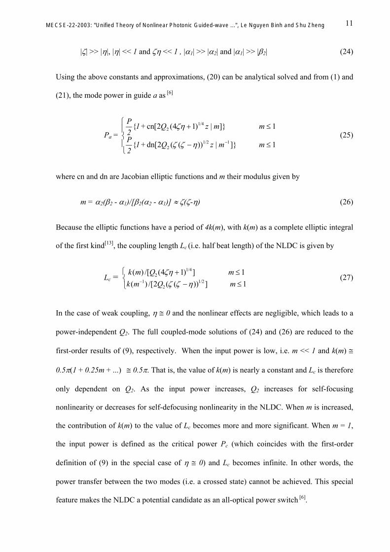
19
Γ3 = Pi2 - [2(Qba/Ksc)Pr-(Kst/Ksc)Pr
2] (50b)
A number of advantages of the reformulated coupled-mode equations (47) in power
parameters, compared to those formulated in modal amplitudes (40) or (41) can be deduced.
Firstly, these constants of motion are z-invariant, namely, they remain constant during the
light propagation and coupling in the coupler system. In other words, during the operation of
the coupler, these special constants of motion, which are functions of the power parameters,
may completely reveal and describe the operation conditions of the whole coupler system.
Secondly, these constants of motion can be determined by the initial launching conditions of
the coupler and can therefore be used to search for the trajectories of the motion or to conduct
stability analysis [7]. Finally, these special relations among the power parameters are very
useful in the search for possible analytical solutions in terms of the mode or cross-mode
powers.
2.2.2.2 Analytical solutions
In this section, an analytical solution is presented for the generalised and optical nonlinear
coupled-mode equations (47) and the results are expressed in terms of the power parameters.
Without losing generality, the practical one-guide launching conditions of a two-mode
couplers are used in the following analysis, namely a(0) = 1 and b(0) = 0. Then the initial
conditions for the power parameters become, by their definition
Pa(0) = 1 and Pb(0) =Pr(0) = Pi(0) = 0 (51)
and, utilising the coupled-mode equations (47 a-d), we have
Pa′(0) = Pb′(0) = Pr′(0) = 0 and Pi′(0)= -Qba (52)
where Qba is defined in (48). From (47) - (50), the following relations can be derived
MECSE-22-2003: "Unified Theory of Nonlinear Photonic Guided-wave ...", Le Nguyen Binh and Shu Zheng

20
(Pa - Pb) = [-(η/ζ)(2Pr-α1)(2Pr-α2)]1/2 and Pi = [γPr(β2-2Pr)]1/2 (53)
in which the following constants are used
ζ = (4Qba/Ksc+2Pab)-1 and η = (2Kct/Ksc-Pab2)(4Qba/Ksc+2Pab)-1 (54a&b)
α1 = -[1+(1+4ζη)1/2]/(2η) ≅ -1/η and α2 = -[1-(1+4ζη)1/2]/(2η) ≅ ζ (54c&d)
β2 = 4Qba/Kst = {1-Pab[2(ζ-η)+Pab]/γ}/(ζ-η) ≅ (1-2Pabζ)/(ζ-η) (54e)
γ = Kst/Ksc = (ζ-η)/ζ +Pab2 ≅ (ζ-η)/ζ (54f)
where in (54c)-(54f), the condition of Pab2 << 1 is used, which is equivalent to that the two
modes are not strongly coupled. From definition of (42) and (43), Kc << K and Kc << Ks are
generally valid, which leads to the following approximations
|ζ| >> |η|, |η| << 1 and ζη << 1 and |α1| >> |α2| and |α1| >> |β2| (55)
Note that if the effects of Pab are totally neglected, the above full coupled-mode equations,
coupling coefficients and constants, i.e. those of (40)-(54) containing the underlined
constants, are reduced to those defined in Ref.[6]. For example, when Pab << 1, ζ → ζ, η →
η, α1 → α1, α2 → α2, β2 → β2, respectively. Therefore, our formulation generalises the
previous ones[1,3,6]. From (47) and (53), we have
2Pr′ = Ksc[(ηγ/ζ)2Pr(2Pr-α1)(2Pr-α2)(2Pr-β2)]1/2 (56a)
∫ [2P02 P zr ( )
r(2Pr-α1)(2Pr-α2)(2Pr-β2)]-1/2d(2Pr) = Ksc(ηγ/ζ)1/2z (56b)
Utilising (54f), we have
Ksc(ηγ/ζ)1/2z ≅ 4Qba[η(ζ -η)]1/2/(1 - 2Pabζ) (57)
MECSE-22-2003: "Unified Theory of Nonlinear Photonic Guided-wave ...", Le Nguyen Binh and Shu Zheng

21
Without the loss of generality, under the assumption of the self-focusing Kerr nonlinearity,
that is
n3,E > 0, α1 < 0, α2
> 0, and n3,E > 0, β2 > 0 ( 58)
The solution of the elliptic integral in (56) can be first expressed in the odd and even Jacobian
elliptic functions of sn and cn[12, 6], respectively, and, utilising the approximations of (55),
leading to
Pr =
>>+
≤≤+
−−
+
)(1)]|(dn1[2
) (1)]|(cn1[2
221
22
βακ
βακ
mmzP
mmzP
(59)
where {κ+, κ-} and m are constants and the modulus of the elliptic functions {cn, dn},
respectively, defined as
κ+ = 2Qba(1 + 4ζη)1/4/(1 - 2Pabζ) and κ- = 2Qba[ζ(ζ - η)]1/2/(1 - 2Pabζ) (60)
m = α2(β2 - α1)/[β2(α2 - α1)] ≅ α2/β2 ≅ ζ(ζ -η)/(1-2Pabζ) (61)
In (60), the conditions of (55) and Pab2 << 1 are used. Due to the periodic properties of the
elliptic functions of cn and dn, the half-beat length of the nonlinear coupler are given by
Lc = ((
1/4
1/2
1 - 2P )1 - 2P )
ab 2 2
ab 2 2
ζ ζη αζ ζ ζ η α
) ( ) / [ ( ) ] () ( ) / [ ( ( )) ] (
k m Q mk m Q m
21
2
4 1 12 1
+ ≤ ββ
≤− ≤ >
− (62)
The analytical solutions (59) and (62) therefore generalise those of Ref.[6], in that the field-
overlap effects (i.e. butt-coupling coefficients and power-nonorthogonality) are accounted for
in our CME and solutions without fully represented formulation. The special case of weak
coupling with negligible field-overlap integrals can be derived from the formulation presented
MECSE-22-2003: "Unified Theory of Nonlinear Photonic Guided-wave ...", Le Nguyen Binh and Shu Zheng

22
in this section and solution by applying the approximation Pab << 1 and the above results are
reduced to those of Ref.[6].
3 Case studies: Nonlinear asymmetric fibre-slab couplers
The reformulation technique adapting the power parameters demonstrated for the optical two-
mode coupler systems is not completely applicable to the optical composite fibre-slab guided-
wave coupling system. This is because that the fibre-slab mode-coupling involves multimodes
and, therefore, an analytical solution to a set of large number of differential equations seems
intractable. In this section, weak guidance, weak linear and nonlinear couplings are assumed.
The fibre-slab nonlinear coupler with third-order nonlinear index distribution can thus be
considered as a linear coupler with a nonlinear perturbation superimposed on its index profile.
The cross sectional structure of such fibre-slab coupler is shown in Figure 2. Such fibre-slab
structure has been analysed under complete linear coupling systems as described in Refs. [15,
16] and its main CME are briefly given in the Appendix. The problems of coupling between a
fiber and an infinite slab in a completely linear system has been extensively investigated[15,18]
with some corrections of the coupling coefficients of such systems[19]. The effect of the
nonlinear coupling is expressed through the index modulation (perturbation) and thus the
induced additional nonlinear coupling coefficients based on the linear, coupled fibre-slab
guided modes. Furthermore a set of scalar, first-order coupled-mode equations is derived for a
typical composite fibre-slab coupler configuration under linear operation and given in the
appendix while the complete coupled equations incorporating both the linear and the
additional nonlinear coupling coefficients are given analytically and examined in the
following sub-sections.
MECSE-22-2003: "Unified Theory of Nonlinear Photonic Guided-wave ...", Le Nguyen Binh and Shu Zheng

23
no
snc
a
nf
x
y0
nst
Figure 2. Cross-sectional view of a fibre-slab waveguide coupler.
3.1 Simplified Scalar CME for Nonlinear Asymmetric fibre-slab Couplers
The refractive indices of the coupler n(x, y) (i.e. over the whole coupler cross-section A∞ ) and
of its different cross-sections {nν( x, y)} (i.e. over the cross-sectional areas of Ao, As, Ac and
Af, with A∞ ≡ Ao+ As+ Ac + Af) can be expressed as
n2 = nL2+ n2|E|2 for (x, y ∈ A∞), nν
2 = nLν2+ n2ν|Eν|2 (x, y ∈ Aν)
and n2 ≡ {n2o, n2s, n2c, n2f} (x, y ∈ A∞) (63)
where ν = {o, s, c f} represents the overlay of the slab (Ao), the slab (As), the fibre cladding
(Ac) and core (Af), the first and second terms correspond to the linear and nonlinear index
profiles, respectively. {E, n2} and {Eν, n2ν} represent the electric fields and the third-order
refractive coefficient of the coupler in each cross-section, respectively. Under scalar
approximations, i.e. assuming weak guidance and coupling of the fibre and slab guided-
modes, the following simplified, first-order CME and the above expression of the nonlinear
index perturbation in (63)
MECSE-22-2003: "Unified Theory of Nonlinear Photonic Guided-wave ...", Le Nguyen Binh and Shu Zheng

24
∑∑ −+++−=N
nnnf
N
nmnmfsmnfff bKabbIaIQa 00
,
200000
'0 j)*(j β (64a)
002
0,
' j)*(j aKbaIbbIQb smn
nsfmn
N
lplpmnplsmnsnmnm −+++−= ∑ ∑βδ (64b)
where a0 and {bm} are the fibre and slab modal amplitudes in the total-field expansion, the
prime sign ′ represent the first derivative with respect to the propagation distance z, {βf0, Qf00,
Kf0n} and {βsn, Qsmn, Ksm0} are the propagation constants, self- and cross-coupling coupling
coefficients of the fibre and slab, respectively. The coupling coefficients under case when the
coupler is under complete linear operating region, consisting of a circular fibre and a planar
slab waveguide are given in the Appendix. Their full and detailed derivations can be found in
Refs. [15, 16]. Whilst {If0, Imnpl}, {Ifsmn, Isfmn} are the additional fibre and slab coupling
coefficients corresponding to the self- and cross-phase modulations, respectively, defined as
If0 = k
f
2
02β∫A∞ n2F0
4dA, Imnpl = k
s
2
2β∫A∞ n2SmSnSpSldA , Ifsmn = k
f
2
02β∫A∞ n2F0
2SmSndA
and Isfmn = k
s
2
2β∫A∞ n2F0
2SmSndA (65)
where k = 2π/λ is the free-space wave number, n2 is the nonlinear coefficient as defined in
(63), F0 and {Sn} are the fundamental fibre mode and the slab mode of transverse order n,
respectively. Note that n2 is generally a cross-sectional distribution of nonlinear coefficients
of the cores and claddings, i.e. n2 = {n2o, n2s, n2c, n2f} and, therefore, it should remain as a part
of the integrand as in (65), rather than be taken out of the integral[3]. In (64), the third and
fourth terms in the right-hand side are the dominant additional nonlinear terms representing
the self- and cross-phase modulation effects, respectively, whilst the nonlinear modulation on
the coupling coefficients and nonlinear coupling at high intensity are assumed negligible[1, 3].
MECSE-22-2003: "Unified Theory of Nonlinear Photonic Guided-wave ...", Le Nguyen Binh and Shu Zheng
25
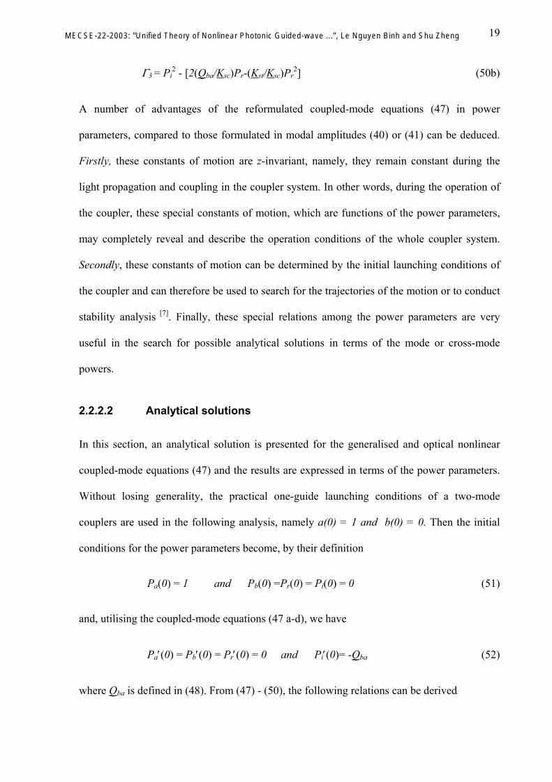
3.2 Coupling Coefficients
We consider, for simplicity, the case that only the overlay of the slab is a Kerr-like nonlinear
medium. In order to obtain an analytical solution of the integrals of the above-defined
nonlinear coupling coefficients, further approximations can be made. Firstly, from the
definition (63) and (65), the cross-phase modulation terms can be ignored in comparison with
the self-phase modulation terms, because the field-overlap terms of the evanescent fields
between the two guides are generally smaller than the mode-power terms. That is, the fourth
terms on the right-hand side of (64) are small compared to the third terms. Secondly, from the
above defined nonlinear index distribution and the notation of (63), we have n2 = {n2o, 0, 0,
0}. Therefore, the integral of the first term of (65) is carried out in the cross-section area of
the slab-overlay cladding only (i.e.∫A∞ → ∫Ao) and, because the integrand is then composed of
very weak evanescent field (i.e. the tails of the field extending into the slab overlay) of the
fibre mode, the integral can be neglected in comparison with the propagation constant βI f 0 f0
and the self-coupling coefficient Qf00, i.e. the first and second terms on the right-hand side of
the first term of (65). The nonlinear self-modulation coefficient Imnpl can therefore be obtained
as:
(i) For the above nonlinear-index distribution, Imnpl of (65) becomes
I k n S S S S dmnpl o m nA p ls= ∫
2
22A (66)
(ii) For the slab overlay, the scalar mode field is given by
S N k tV
en As s
so
x a s tn
o
o= − − + +
2γ σ[ ( )] cos( y) (67)
(iii) Substituting (67) into (66), the exact solution of Imnpl can be expressed as
MECSE-22-2003: "Unified Theory of Nonlinear Photonic Guided-wave ...", Le Nguyen Binh and Shu Zheng

26
IDk N k t
Vmnplo
o
s s
som n p l m n p l m n p l m n p l= + + ++ − − + + − + + − + + − + +
αγ
δ δ δ δ2
40 1 0 1 0 14
( ) { ( ), ( ), ( ), (
+
+ 0),
+ +− − − − − + − − − +δ δ δ( ), ( ), ( ), }m n p l m n p l m n p l1 0 0 0 (68)
3.3 Optical power tuning operations of the nonlinear asymmetric couplers
Numerical calculations have been carried out using practical parameters at a light wavelength
λ = 1.55 µ m, with fibre radius a = 2.5 µ m, slab thickness t = 3 µ m, refractive index of the
fibre cladding nc = 1.46, ns = 1.4745, and the distance between the fibre and the slab s = 0.5
µ m. The typical value of the self-focusing, nonlinear refractive index n3,Io = 10-9 m2/W [6] is
used and n2o = cε0no
2n3,Io can be obtained, where no is the slab-overlay index of refraction,
whilst c and ε0 are the free-space light speed and dielectric constant, respectively.
Initially, the lightwave is launched (with unit power) into the fibre to excite its fundamental
mode. Figure 2 shows that, when the core index of refraction of the fibre is greater than that
of the slab, i.e. nf = 1.4817 > ns =1.4745, (the fibre mode is out of phase with those of the slab
transverse modes) the nonlinear effect is mainly displayed in the form of phase shift. The
launched power largely remains in the fibre whilst a small amount couples back and forth
between the fibre and the slab with an extended beat length (as a result of the nonlinear phase
modulation of the guided modes).
When the fibre-core index of refraction is reduced to nf = 1.4756 (greater than ns =1.4745,
although the coupler is getting close to a phase match), Figure 3 demonstrates the interesting
nonlinearity-assisted coupling which transfers up to a possible 100% of the total power from
the fibre to the slab. However, it appears that the exact amount of power transferred depends
on the interaction (i.e. total coupling) length of the coupler due to the slow oscillation of the
power between the two guides.
MECSE-22-2003: "Unified Theory of Nonlinear Photonic Guided-wave ...", Le Nguyen Binh and Shu Zheng

27
|a0|2
0.8
0.85
0.9
0.95
1
0 200 400 600 800 1000 1200
(1)(2)
Figure 3. Propagation of |a0(z)|2. nf = 1.4817, ns =1.4745, nc = 1.40 : (1) scalar CMT
without nonlinearity; (2) scalar CMT with nonlinearity –this work.
When the core refractive indices become equal, i.e. nf = ns =1.4745, the coupler is almost
exactly phase-matched (i.e. βf0 ≅ βs) and Figures 5 and 6 further indicate the nonlinearity-
assisted coupling, with a nearly complete power transfer in this case. The above phenomenon
of optically-enhanced coupling may be explained by the phase-detuning effect[1] due to the
nonlinear phase modulation. The phase modulation is optically induced, initially starting in
the fibre (the launching guide) and moves into the slab as the light is gradually coupled from
the fibre to the slab. Here the slab self-phase modulation (67) is the contributing factor to the
enhanced, phase-matched coupling, which drives the coupler to the state of a full power
transfer (in analogy to the crossed state of a two-mode coupler).
MECSE-22-2003: "Unified Theory of Nonlinear Photonic Guided-wave ...", Le Nguyen Binh and Shu Zheng

28
|a0|2
0
0.2
0.4
0.6
0.8
1
0 200 400 600 800 1000 1200 1400 1600
(1)(2)
Figure 4. Propagation of |a0(z)|2. nf = 1.4756, ns =1.4745, nc = 1.40 : (1) scalar CMT
without nonlinearity; (2) scalar CMT with nonlinearity – this work.
Finally, when the fibre-core refractive index becomes smaller than that of the slab, i.e. nf =
1.4709 < ns =1.4745, the fibre mode is phase-matched with one of the slab transverse modes
(i.e. at the absence of the nonlinear effect). As a result, the nonlinearity does not seem to
significantly assist the coupling in terms of the power transfer, if at all. Instead, it alters the
power-beating properties, such as the beat length and the amplitudes of the power oscillation,
through the nonlinear phase self-modulation.
|a0|2
0
0.2
0.4
0.6
0.8
1
0 200 400 600 800 1000 1200 1400 1600 1800
(1)(2)
MECSE-22-2003: "Unified Theory of Nonlinear Photonic Guided-wave ...", Le Nguyen Binh and Shu Zheng

29
Figure 5. Propagation of |a0(z)|2. nf = 1.4745, ns =1.4745, nc = 1.40 : (1) scalar CMT
without nonlinearity; (2) scalar CMT with nonlinearity – this work.
|a0|2
0
0.2
0.4
0.6
0.8
1
0 500 1000 1500 2000
(1)(2)
Figure 6. Propagation of |a0(z)|2. nf = 1.4709, ns =1.4745, nc = 1.40 : (1) scalar CMT
without nonlinearity (2) scalar CMT with nonlinearity – this work.
4 Concluding remarks
A unified theoretical analysis has been developed and described for nonlinear asymmetric
optical couplers utilising the scalar CMT whilst treating the effect of Kerr-like nonlinearity as
a perturbation on the index-profile of the whole coupler structure. The most general cases (i.e.
including the nonlinear guided-modes and power-nonorthogonality) are considered and full,
power-conserved and nonorthogonal coupled-mode equations in the power parameters are
proposed and analytically solved. Without losing simplicity (e.g. the format of the simplified
analysis), the new formulations and solutions generalise the previous results[1,3,6] with all the
coupling coefficients and constants updated to include the mode-nonorthogonality (i.e. the
filed-overlap effects) ignored previously.
This generalised analysis would find immediate application in the design and analysis of
optical nonlinear guided two-mode coupler system, especially for the cases of weak guidance
MECSE-22-2003: "Unified Theory of Nonlinear Photonic Guided-wave ...", Le Nguyen Binh and Shu Zheng

30
and weak to moderate nonlinear couplings. A simplified, scalar coupled-mode analysis is
presented to demonstrate the essential nonlinear effects on the optical composite fibre-slab
guided-wave couplers. A simple, numerical example is used to demonstrate some interesting
nonlinear coupling features that are quite similar to those of the grating-assisted coupling in a
fibre-slab coupler which would be described in another article. When the parameters of the
coupler are such that there is no phase synchronism between the fibre and the slab modes, the
nonlinear phase-modulation comes into play and it assists coupling, resulting in up to a total
power transfer from the fibre to the slab. However, when there is a phase synchronism
between the two sets of guided modes, the effects of the Kerr-like nonlinearity seems greatly
reduced and displayed as some minor changes to the small power beating on the power-decay
curve.
Based on the above nonlinearity-assisted coupling feature we can propose an all-optical, in-
line fibre to slab coupler device that is easy to fabricate, considering the matured polished-
fibre or D-fibre technique. This composite fibre-slab guided-wave system may find immediate
applications in the areas of in-line fibre couplers for optical switching and sensing
technology. It may be designed to achieve the desired level of power transfer from the fibre
(in-line) to the slab waveguide through an optimised selection of the materials and launched
power.
5 References
[1] Jensen, S. M., “The nonlinear coherent coupler” IEEE J. Quantum Electron., vol. QE-18, pp.1580-1583, 1982.
[2] Thylen, L., Wright, E. M., Stegeman, G. I., Seaton, C. T. and Moloney, J. V., “Beam propagation method analysis of a nonlinear directional coupler exhibiting a Kerr nonlinearity” Opt. Lett. 11, QE-24, pp.739-741, 1986.
[3] Chen, Y., “Solution to full coupled mode equations for nonlinear coupled systems”, IEEE J. Quantum Elect., vol. 25, No. 10, pp. 2149-2153, 1989.
MECSE-22-2003: "Unified Theory of Nonlinear Photonic Guided-wave ...", Le Nguyen Binh and Shu Zheng

31
[4] Cada, M. and Begin, J. D., “An analysis of a planar directional coupler with a lossless Kerr-like coupling medium” IEEE J. Quantum Electron. Vol. 26, pp. 361-371, 1990.
[5] see Chuang, S. L. “A coupled-mode formulation by reciprocity and a variational principle” J. Lightwave Technol. LT-5, pp.5-15, 1987 and Chuang, S. L., “Application of the strongly coupled-mode theory to integrated optical devices” IEEE J. Quantum Electron. QE-23, pp.499-509, 1987.
[6] Meng, X. J. and Okamoto, N. (1991) “Improved Coupled-Mode Theory for Nonlinear Directional Couplers” IEEE J. Quantum Electron. Vol.27, pp.1175-81, 1991.
[7] Daino, B., Gregori, G. and Wabnitz, S., “Stability analysis of nonlinear coherent coupler”, J. Appl. Phys. 58 (12), pp. 4513-4514, 1985.
[8] Pham, A.T. and Binh, L.N., “Nonlinear optical directional coupler used as optical amplifier with twin biasing beams”, Int. J. Optoelectron. 5, pp. 381-386, 1990.
[9] Pham, A.T. and Binh, L.N., “All-optical modulation and switching using a nonlinear-optical directional coupler”, J. Opt. Soc. Am. B, vol. 8, pp. 1914-1931, 1991.
[10] Snyder, A. W., Mitchell, D. J., Poladian, L., Rowland, D. R. and Chen, Y., “Physics of nonlinear fiber couplers”, J. Opt. Soc. Am. B., vol. 8, pp. 2102-2118, 1991.
[11] Shen, Y. R. “The principles of nonlinear optics”, Wiley, New York, 1984.
[12] Sammut, R. A. and Pask, C., “Gaussian and equivalent-step-index approximations for nonlinear waveguides” J. Opt. Soc. Am. B, vol. 8, No.2, pp. 395-402, 1991.
[13] Abramowitz, M. and Stegan, I. A., “Handbook of mathematical functions” New York: Dover, 1965.
[14] Ankiewicz, A., “Novel Effects in Non-linear Coupling” Opt. Quant. Elect., vol. 20, pp. 329-337, 1988.
[15] Marcuse, D., “Investigation of coupling between a fiber and an infinite slab”, IEEE J. Lightw. Tech., vol. 7, pp. 122-130, 1989.
[16] Zheng S., G.P. Simon and Binh, L.N., “Light coupling and propagation in composite optical-fiber slab waveguides”, IEEE J. Lightw. Tech., vol. 13, pp. 244-251, 1995.
[17] Snyder A. and Chen Y., “Nonlinear fibre couplers: switches and polarisation splitters”, Opt. Lett., vol. 14, pp. 517-519.
[18 ] Marcuse, D., “Directional couplers made of non-identical asymmetric slab: Part I: synchronous couplers”, IEEE J. Lightw. Tech., vol. LT-5, No. 1, pp. 113-118, 1987.
[19] Marcuse, D., Personal communications in relation to the paper of D. Marcuse [19].
MECSE-22-2003: "Unified Theory of Nonlinear Photonic Guided-wave ...", Le Nguyen Binh and Shu Zheng

32
6 Appendix: CMEs of The Fibre-Slab Linear Coupling System
The transverse electric field in the coupled fibre and slab waveguides can be well represented
by the superposition of the guided-modes of the fibre and the slab, i.e. {F , 0 Sn}
E x y z a z F x y b z S x yn nn
( , , ) ( ) ( , ) ( ) ( , )= + ∑0 0 (A1)
where {a0(z), b (z)} (n = 0, 1, 2, ...) is a set of z-dependent expansion (excitation) coefficients
(modal amplitudes), whilst the summation is carried out over the set of discretised transverse
slab modes of the planar waveguide.
n
In the co-ordinate system shown in Figure 2, the dominant LP01 mode (the transverse electric
field) of the isolated fibre is given by
F N
J k rJ k aK rK a
forr a
r af
f
f
f
f
0
0
0
0
0
=
≤
>
( )( )( )( )γγ
(A2)
where J0 and J1 are the Bessel functions of the first kind, K0 is the modified Bessel functions
of the second kind and NJ k a
V J k aff f
f f
=γπ
0
1
( )( )
is the normalisation constant of the fibre mode.
The parameter a denotes the fibre radius, kf2= nf
2k2- βf02 and γf
2= βf02
- nc2k2 are constants in
which k = 2π/λ (λ is the free-space light wavelength), βf0 is the propagation constant obtained
from the LP01 mode dispersion equation[5] and nf and nc are the refractive indices of the fibre
core and cladding respectively. Vf = ka(nf2-nc
2)1/2 is a dimensionless waveguide parameter
related to kf and γf via
Vf2 = a2(kf
2+γf2) (A3)
MECSE-22-2003: "Unified Theory of Nonlinear Photonic Guided-wave ...", Le Nguyen Binh and Shu Zheng

33
In the same co-ordinate system (i.e. Figure 2), the nth guided transverse slab mode is obtained
in the form
Sn(x,y) =
Nscos(σny)V x h V
k x h t k k x h tx h t
x a sfor a s x a s
x a s t
so c sc
s o s s
o
exp[ ( )] /{cos[ ( )] ( / )sin[ ( )]}
exp[ ( )]t
γγ
γ
−− − − − −
− − −
< ++ ≤ ≤ + +> + +
(A4)
where n = 0, 1, 2, ..., k =2π/λ, ks2=ns
2k2-βs2, γc
2=βs2-nc
2k2, γo2=βs
2-no2k2, Vsc=kt(ns
2-nc2)1/2/2,
Vso=kt(ns2-no
2)1/2/2, Nt Ds
c o
o c c o
=+ +
[( )
]2 12γ γ
γ γ γ γ
2n
is the normalisation constant and σn is defined
from for n= 0,1,2…., i.e. the transverse propagation constant of the lightwaves
travelling along the z-direction. The parameter t denotes the slab thickness, s the minimum
distance between the surface of the fibre core and that of the polished flat (see Figure 1(b)), β
22ssn σββ −=
s
is the propagation constant of the slab mode, ns and no are the refractive indices of the slab
and the overlay cladding, respectively. Vsc and Vso are dimensionless waveguide parameters
related to ks, γc and γo via
Vsc2 = t2(ks
2+γc2)/4 and Vso
2 = t2(ks2+γo
2)/4 (A5)
The propagation constant βs of the slab guided mode of the mth order can be obtained from
the well known dispersion equation of the asymmetric planar slab waveguide
kst-tan-1(γc/ks)-tan-1(γo/ks) = mπ (m = 0, 1, 2, ...) (A6)
The CME are obtained when the field expansion (A1) is substituted into the wave equation of
the total field, and then the resultant equation is multiplied successively with F0 and Sn and
integrated over the transverse (x, y) plane whilst making use of the wave equations and
MECSE-22-2003: "Unified Theory of Nonlinear Photonic Guided-wave ...", Le Nguyen Binh and Shu Zheng

34
orthogonal relations of the fibre and slab modes. Using the scalar approximations, i.e.
assuming a slowly varying envelope of the modal amplitudes and weakly coupled fibre and
slab modes, both the second-order derivatives and the field overlap integrals may be
neglected[15] and the following first-order coupled-mode equations are derived
a0′ = -j(βf00+Qf00)a0 - j K f nn
0∑ bn (A7.a)
bm′ = -j (δ mnn∑ βsn+Qsmn)bn - jKsm0a0 (A7.b)
where a , dadz0
0' = b , m, n = 0, 1, 2, ..., δdbdzm
m' = mn is the Kronecker delta function, {Qf00, Qsmn}
and {Kf0n, Ksm0} are the self- and cross-coupling coefficients, respectively. They are defined
as follows
Q k n x y n x y F F dAff
fA000
= −∫∞
22 2
0 02β[ ( , ) ( , )] (A8.a)
Q k n x y n x y S S dAsmnsm
sA m n= −∫∞
22 2
2β[ ( , ) ( , )] (A8.b)
K k n x y n x y F S dAf nf
sA n0
2
0
2 202
= −∫∞β[ ( , ) ( , )] (A.9a)
K k n x y n x y S F dAsmsm
fA m0
22 2
02= −∫
∞β[ ( , ) ( , )] (A9b)
where m, n = 0, 1, 2, ..., dA = dxdy and A∞ indicates integration over the infinite cross-section,
i.e. the entire transverse (x, y) plane, of the coupler system. From the refractive index profiles
the coupling coefficients defined above can be categorised in two ways. {Q ,Q } are self
coupling coefficients that represent the coupling among the fibre or slab modes due to the
presence of the other, {
f 00 smn
K f n0 ,Ksm0 } are cross coupling coefficients that couple the slab modes
to the fibre mode or vice versa.
MECSE-22-2003: "Unified Theory of Nonlinear Photonic Guided-wave ...", Le Nguyen Binh and Shu Zheng

35
The above integrals are all solved exactly except Qf00, for which a large-argument asymptotic
approximation of the modified Bessel function K0 has to be used. The closed-form
expressions of the coupling coefficients are given below
QN Vt a
a s t a s A a s tff sc
f f ff f s f00
2 2 2
02 22
2 2 2= + + − + +π
β γ γγ γ γ
Kerf erf erfc
02 ( )
[ ( ( ) ) ( ( ) ) ( ( ) )+ + ]
(A.10a)
QN k V t
Va
a
a
asmn
s s fa s
sm sc
c m n
c m n
c m n
c m n
c
=− +
− ++
− −
− −
− +πβ
γ σ σ
γ σ σ
γ σ σ
γ σ σ
γ2 2 2 2 2
2
2 2
2 2
2 2
2 284
4
4
4
e I I1 1( )
[( ( ) )
( )
( ( )
( )]
)
(A.10b)
KN N V k t
aV k a kk a a k k a af n
f s f sa s
f sc f f c nc n f c n f f c n
c
0
2
02 2 2
2 2 2 2 2 2
2=
+ −− − +
− +πβ γ σ
γ σ γ σ γ σγe
JJ J
00 1 1 0
( )
( )( )[ ( )I ( ) ( )I ( )]−
(A.11a)
KN N V k
a t
Bksn
f s sc sa s
sn f f n
f n c s f n ot
s f n
f n f n
0 2 2
2 2 2 2
2 2 2
2 2 2 2
=+
+ + − + −
+ +
− + + − +π
β γ γ σ
γ σ γ γ σ γ
γ σ
γ σ γ σe
K0
( )
( )
( )e
++ +
− +A Bs st
o f
f ne γ σ
γ γ σ
2 2
2 2n
(A.11b)
where V k , a n nf f c= −2 2 V , kt n nsc s c= −2
2 2 V , kt n nso s o= −2
2 2 A , n nn ns
o c
s c
=−−
2 2
2 2 B , VVs
sc
so
=
B VVs
sc
so
= , erf(x) is the error function, erfc(x) = 1 - erf(x), I0 and I1 are the modified Bessel
functions of the first kind. In the above expressions, the new parameters As and Bs are
introduced to quantify the geometric asymmetry of index profile of the slab waveguide. For
the case involving a symmetric slab waveguide, we have As = 0 and Bs = 1.
MECSE-22-2003: "Unified Theory of Nonlinear Photonic Guided-wave ...", Le Nguyen Binh and Shu Zheng