Embed Size (px)
Citation preview
1
LABORATORY
MANUAL ON
THEORY OF MACHINE AND
MEASUREMENT OF
4TH Semester
MECHANICAL Engineering
DEPARTMENT OF MECHANICAL ENGINEERING
Govt. Polytechnic Sambalpur
Rengali
2
INTRODUCTION
Theory of machine is the branch of engineering which deals with
the study of relative motion and force between various machine
elements.
Measurement is a process of determining any quantity by using
various measuring instruments.
Theory of machine and measurement lab includes different types
machines with different mechanisms as well as the various types of
measuring instruments used in the field of Engineering and
Technology.
This laboratory manual provides practical knowledge to the
students for understanding different mechanisms of machines and
the use of different measuring instruments.
3
LIST OF EQUIPMENTS OF THEORY OF MACHINE AND MEASUREMENT LAB
SL NO. NAME OF APPARATUS QUANTITY
01
GOVERNOR APPARATUS
01No
02 STATIC AND DYNAMIC APPARATUS 01No
03 JOURNAL BEARING APPARATUS 01 No
04 CAM ANALYSIS APPARATUS 01 set
05 EPICYCLIC GEAR TRAIN 01 No
06 VERNIER CALLIPER 01 Nos.
07 MICROMETER 06 Nos.
08 VERNIER HEIGHT GAUGE 01 Nos.
09 SLIP GAUGE 01 set.
10 SINE BAR 01 Nos.
4
CONTENTS
SL. No Name of the Experiments Page No.
1 Determination of centrifugal force of a governor (Hart Nell /
Watt/Porter).
1-4
2 Study & demonstration of static balancing apparatus. 5-7
3 Study & demonstration of journal bearing apparatus. 8-10
4 Study of different types of Cam and followers. 11-13
5 Study & demonstration of epicyclic gear train. 14-15
6 Determination of the thickness of ground M.S flat to an accuracy of
0.02mm using Vernier Caliper.
16-17
7 Determination of diameter of a cylindrical component to an
accuracy of 0.01mm using micrometer.
18-20
8. Determine the heights of gauge blocks or parallel bars to accuracy
of 0.02mm using Vernier height gauge.
21-23
9. Determine the thickness of ground MS plates using slip gauges. 24-25
10. Determination of angel of Machined surfaces of components using
sin bar with slip gauges.
26-27
5
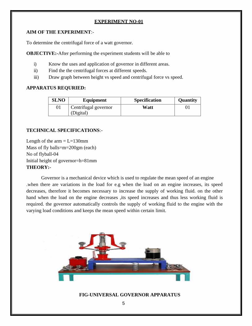
EXPERIMENT NO-01
AIM OF THE EXPERIMENT:-
To determine the centrifugal force of a watt governor.
OBJECTIVE:-After performing the experiment students will be able to
i) Know the uses and application of governor in different areas.
ii) Find the the centrifugal forces at different speeds.
iii) Draw graph between height vs speed and centrifugal force vs speed.
APPARATUS REQURIED:
SLNO Equipment Specification Quantity
01 Centrifugal governor (Digital)
Watt 01
TECHNICAL SPECIFICATIONS:-
Length of the arm = L=130mm
Mass of fly balls=m=200gm (each)
No of flyball-04
Initial height of governor=h=81mm
THEORY:-
Governor is a mechanical device which is used to regulate the mean speed of an engine
.when there are variations in the load for e.g when the load on an engine increases, its speed
decreases, therefore it becomes necessary to increase the supply of working fluid. on the other
hand when the load on the engine decreases ,its speed increases and thus less working fluid is
required. the governor automatically controls the supply of working fluid to the engine with the
varying load conditions and keeps the mean speed within certain limit.
FIG-UNIVERSAL GOVERNOR APPARATUS
6
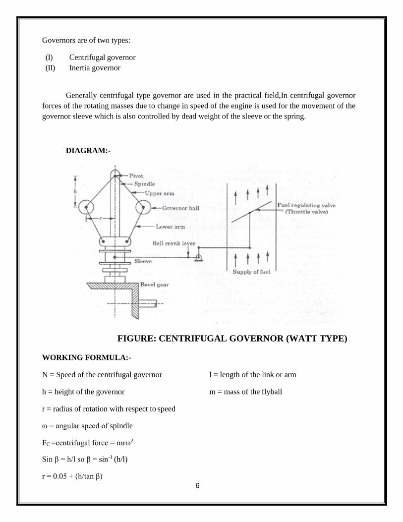
Governors are of two types:
(I) Centrifugal governor
(II) Inertia governor
Generally centrifugal type governor are used in the practical field,In centrifugal governor
forces of the rotating masses due to change in speed of the engine is used for the movement of the
governor sleeve which is also controlled by dead weight of the sleeve or the spring.
DIAGRAM:-
FIGURE: CENTRIFUGAL GOVERNOR (WATT TYPE)
WORKING FORMULA:-
N = Speed of the centrifugal governor l = length of the link or arm
h = height of the governor m = mass of the flyball
r = radius of rotation with respect to speed
ω = angular speed of spindle
FC =centrifugal force = mrω2
Sin β = h/l so β = sin-1 (h/l)
r = 0.05 + (h/tan β)
7
ω = 2πN/60
PROCEDURE:-
1. The links are fixed as per the diagram.
2. Ensure that all the fittings are tight.
3. With the help variable voltage supply slowly increases the rpm of the governor.
4. Note down the respective speed.
5. Note down the lift of the sleeve, due to increase in speed.
6. Take five readings at variable speeds.
7. Plot height vs speed and centrifugal forces vs speed graphs from the above readings.
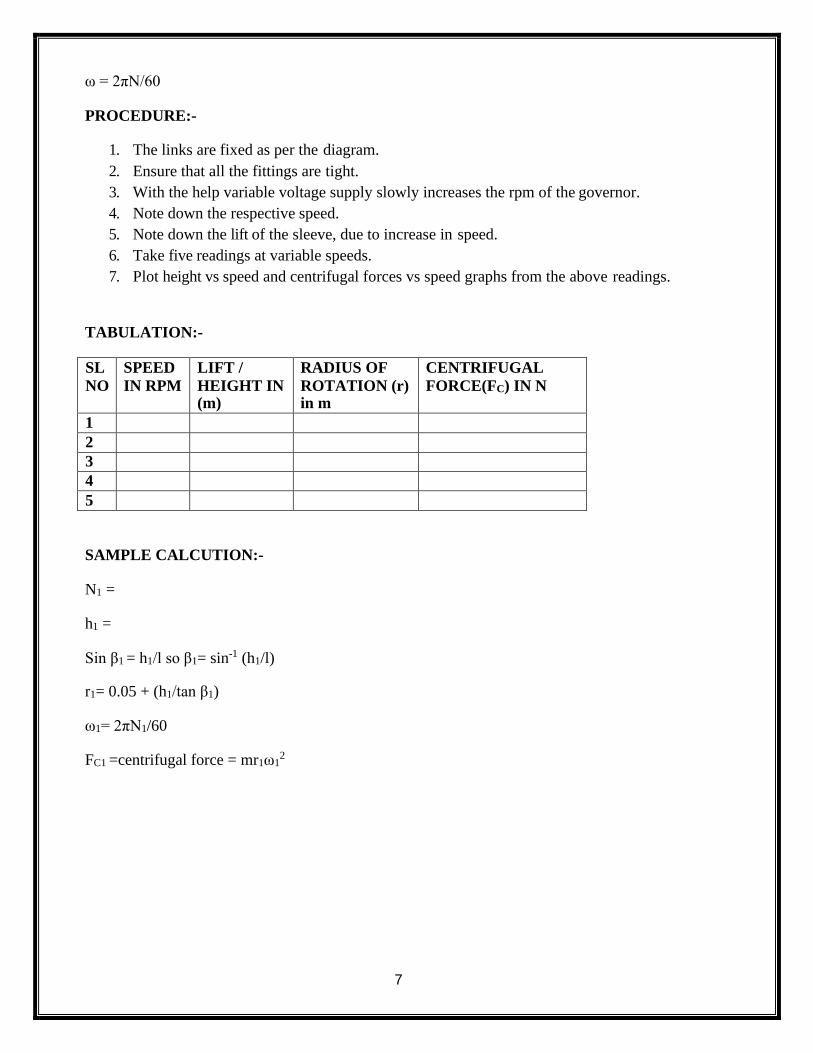
TABULATION:-
SL
NO
SPEED
IN RPM
LIFT /
HEIGHT IN (m)
RADIUS OF
ROTATION (r) in m
CENTRIFUGAL
FORCE(FC) IN N
1
2
3
4
5
SAMPLE CALCUTION:-
N1 =
h1 =
Sin β1 = h1/l so β1= sin-1 (h1/l)
r1= 0.05 + (h1/tan β1)
ω1= 2πN1/60
FC1 =centrifugal force = mr1ω12
8
CONCLUSION:
From the above experiment, we study and calculate the centrifugal forces at different speed of watt
governor and hence plotted the graph.
PRECAUTION:-
i) Do not touch the equipment while in running condition
ii) Use safety shoes.
iii) Before starting the experiment check all the fittings.
VIVA VOICE:-
i) Define governor.
ii) Define centrifugal force.
iii) State different parts of governor.
iv) Explain the working of a governor.
v) Explain the construction and working of a governor.
vi) State the uses of governor in daily life
vii) Differentiate between flywheel and governor.
9
EXPERIMENT NO-02
AIM OF THE EXPERIMENT:-To study about static balancing apparatus.
OBJECTIVES:- After performing the experiment students will be able to
i) Explain the needs of balancing.
ii) Calculate the position of balancing mass and radius of gyration.
iii) Draw the graphical representation of the balancing mass.
APPARATUS REQUIRED:-
SL NO
Equipment Specification Quantity
01 Static blanching Apparatus
01
02 Block of different
weight 06
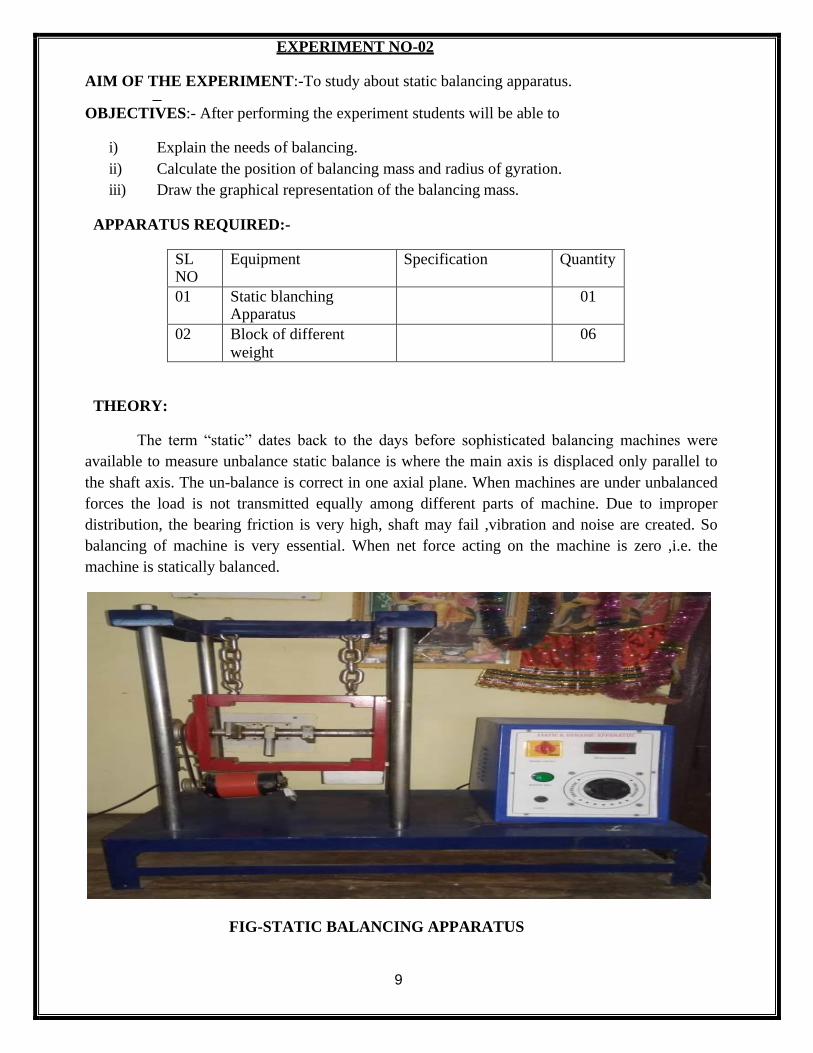
THEORY:
The term “static” dates back to the days before sophisticated balancing machines were
available to measure unbalance static balance is where the main axis is displaced only parallel to
the shaft axis. The un-balance is correct in one axial plane. When machines are under unbalanced
forces the load is not transmitted equally among different parts of machine. Due to improper
distribution, the bearing friction is very high, shaft may fail ,vibration and noise are created. So
balancing of machine is very essential. When net force acting on the machine is zero ,i.e. the
machine is statically balanced.
FIG-STATIC BALANCING APPARATUS
10
WORKING FORMULA:-
∑H= m1 r1 cosɵ1 +m2 r2 cosɵ2 +m3 r3 cosɵ3 ….
∑V= m1 r1 sin ɵ1 +m2 r2 sin ɵ2 +m3 r3 sin ɵ3 ….
R=√(∑H2+∑V2)
Ɵ = tan-1 (∑V/∑H)
Position of balancing mass=Ɵ+1800
F4= m4 r4ω2
PROCEDURE:-
1. Suspend the frame slowly in the balancing apparatus.
2. By using sprit level check the horizontal plane.
3. Start the motor and check the horizontal plane.
4. Stop the motor and add one disturbing mass to the shaft of known radius of rotation.
5. Tabulate the readings.
6. Draw force polygon
7. Find the balancing force and position from the force polygon.
TABULATION:-
Sl.No. Mass in kg Radius (r) in mm
Subtented
angle
(counter
clock wise)
Product m*r
01
02
03
04
05
11
SAMPLE CALCULATION
∑H= m1 r1 cosɵ1 +m2 r2 cosɵ2 +m3 r3 cosɵ3 =___________
∑V= m1 r1 sin ɵ1 +m2 r2 sin ɵ2 +m3 r3 sin ɵ3=___
R=√(∑H2+∑V2)=
Ɵ = tan-1 (∑V/∑H)=
_
Position of balancing mass=Ɵ+1800=
F4= m4 r4ω2 =
CONCLUSION:-
Hence we successfully calculate the position of balancing mass.
PRECAUTION:-
i) Do not touch the equipment while in running condition
ii) Use safety shoes.
iii) Before starting the experiment check all the fittings.
VIVA VOICE:-
i) Define balancing?
ii) Need of balancing?
iii) Types of balancing?
iv) What is static balancing?
v) What are the disadvantages of unbalanced machine?
12
EXPERIMENT NO-03
AIM OF THE EXPERIMENT:-
To study and demonstration of journal bearing apparatus.
OBJECTIVES:- After performing the experiment students will be able to
i) Explain the needs of bearing.
ii) What is journal bearing?
APPARATUS REQUIRED:-
SL. NO.
Equipments Specification Quantity
01 M.S bearing mounted freely on journal shaft
01
02 Motor A.C 0.5HP 01
03 Balancing weight 1kg 01
04 Manometer Board -- 01
05 Flexible tube -- 16.
06 Oil reservoir -- 01
07 Collecting tank oil -- 01
08 Oil (Red color) SEA40 --
Technical Specification:-
1. Diameter of journal =
2. Diameter of bearing(outer)=
3. Diameter of bearing (Inner)=
4. Bearing width=
5. Weight =
6. Motor=
7. Motor Control= Dimmer start
8. Manometer board with 16 tubes with suitable scales and oil supply tank.
9. Recommended oil=
10. Supply required=
THEORY:-
Journal bearing is designed on the basis if hydrodynamic bearing action used in practice to
formulate the bearing action accurate in mathematical terms is a more complex job.
However one can visualize pattern of bearing pressure distribution due to hydrodynamic
action with the help of experimental rig. This helps to understand the subject properly. The
experimental test rig consists of small journal bearing. This apparatus helps to demonstrate and
13
study effect of important variables such as- speed, viscosity and load on the pressure distribution
can be verified with summer field equation.
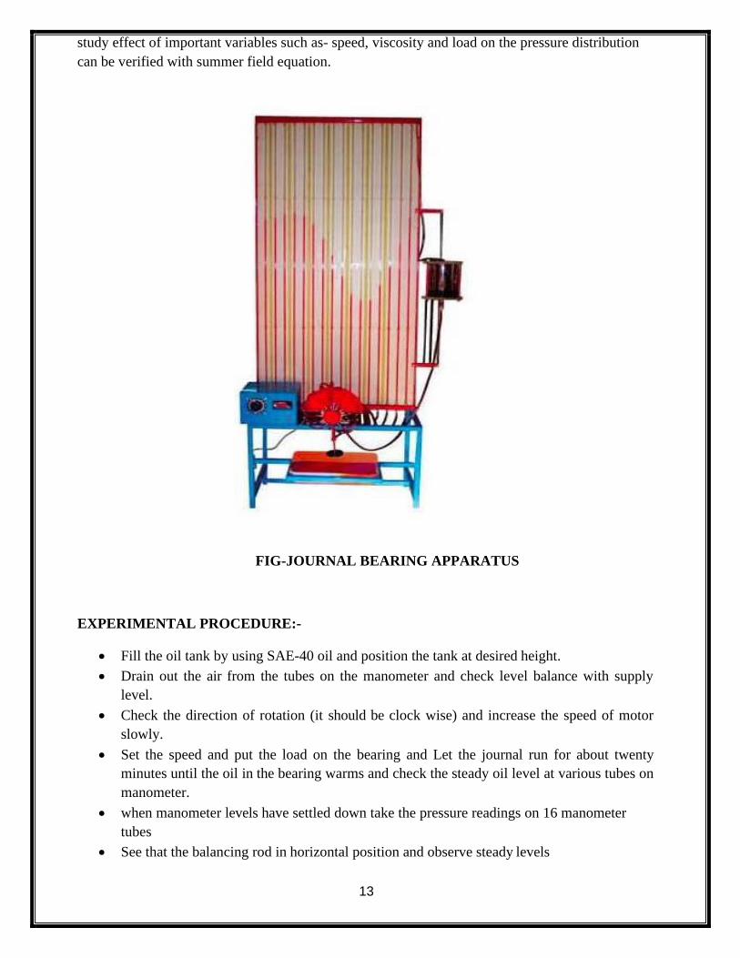
FIG-JOURNAL BEARING APPARATUS
EXPERIMENTAL PROCEDURE:-
• Fill the oil tank by using SAE-40 oil and position the tank at desired height.
• Drain out the air from the tubes on the manometer and check level balance with supply
level.
• Check the direction of rotation (it should be clock wise) and increase the speed of motor
slowly.
• Set the speed and put the load on the bearing and Let the journal run for about twenty
minutes until the oil in the bearing warms and check the steady oil level at various tubes on
manometer.
• when manometer levels have settled down take the pressure readings on 16 manometer
tubes
• See that the balancing rod in horizontal position and observe steady levels
14
• Repeat the experiment for various speeds and lends.
• After the test is over set the dimmer to zero & switch off the power.
• Keep the oil tank at lower most position so that there will be leant leakage in ideal period
TABULATION-
SL.NO P(mm) (P-P0)max remarks
01
02
03
04
05
06
07
08
09
10
11
12
CONCLUSION:-
Form the above experiment, we have successful studies and verify about journal bearing
apparatus.
PRECAUTION:-
i) Do not touch the equipment while in running condition
ii) Use safety shoes.
iii) Before starting the experiment check all the fittings.
VIVA VOICE:-
i) Define journal bearing.
ii) What is the need of bearing?
iii) State some bearing material.
iv) What is the name of the lubricating oil used in this experiment
15
EXPERIMENT NO-04
AIM OF THE EXPERIMENT:-
To study about different types of cam and Follower.
OBJECTIVES:- After performing the experiment students will be able to
i) Understand uses of cam and follower.
ii) Understand mechanism of cam and follower.
iii) Know different types of cam and follower.
APPARATUS REQUIRED:-
SL NO
Equipment Specification Quantity
01 MODELS OF CAM AND FOLLOWER
THEORY:-
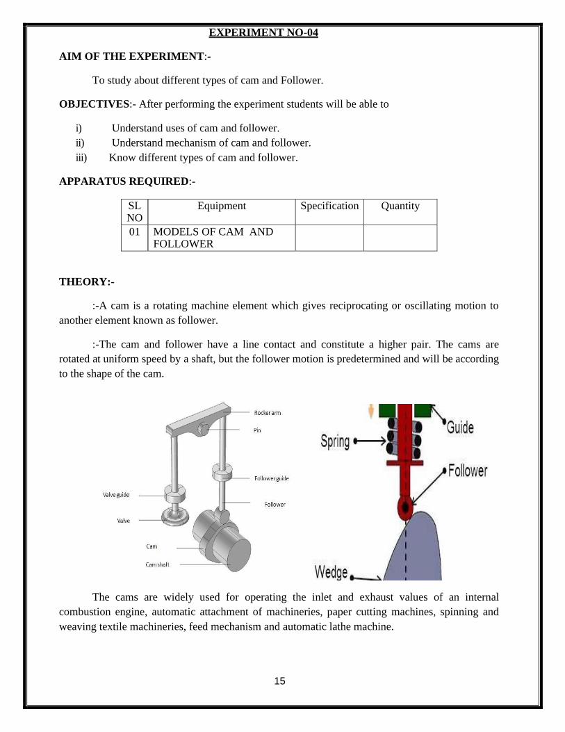
:-A cam is a rotating machine element which gives reciprocating or oscillating motion to
another element known as follower.
:-The cam and follower have a line contact and constitute a higher pair. The cams are
rotated at uniform speed by a shaft, but the follower motion is predetermined and will be according
to the shape of the cam.
The cams are widely used for operating the inlet and exhaust values of an internal
combustion engine, automatic attachment of machineries, paper cutting machines, spinning and
weaving textile machineries, feed mechanism and automatic lathe machine.
16
TYPES OF CAM AND FOLLOWER:-
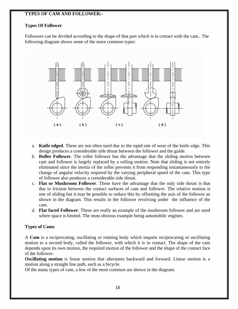
Types Of Follower
Followers can be divided according to the shape of that part which is in contact with the cam.. The
following diagram shows some of the more common types:
a. Knife edged. These are not often used due to the rapid rate of wear of the knife edge. This
design produces a considerable side thrust between the follower and the guide.
b. Roller Follower. The roller follower has the advantage that the sliding motion between
cam and follower is largely replaced by a rolling motion. Note that sliding is not entirely
eliminated since the inertia of the roller prevents it from responding instantaneously to the
change of angular velocity required by the varying peripheral speed of the cam. This type
of follower also produces a considerable side thrust.
c. Flat or Mushroom Follower. These have the advantage that the only side thrust is that
due to friction between the contact surfaces of cam and follower. The relative motion is
one of sliding but it may be possible to reduce this by offsetting the axis of the follower as
shown in the diagram. This results in the follower revolving under the influence of the
cam.
d. Flat faced Follower. These are really an example of the mushroom follower and are used
where space is limited. The most obvious example being automobile engines.
Types of Cams
A Cam is a reciprocating, oscillating or rotating body which imparts reciprocating or oscillating
motion to a second body, called the follower, with which it is in contact. The shape of the cam
depends upon its own motion, the required motion of the follower and the shape of the contact face
of the follower.
Oscillating motion is linear motion that alternates backward and forward. Linear motion is a motion along a straight line path, such as a bicycle.
Of the many types of cam, a few of the most common are shown in the diagram.
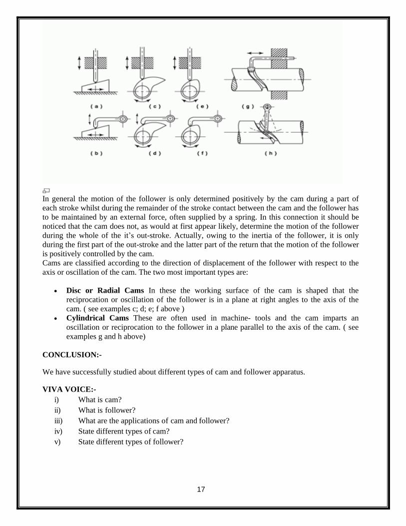
17
In general the motion of the follower is only determined positively by the cam during a part of
each stroke whilst during the remainder of the stroke contact between the cam and the follower has
to be maintained by an external force, often supplied by a spring. In this connection it should be
noticed that the cam does not, as would at first appear likely, determine the motion of the follower
during the whole of the it’s out-stroke. Actually, owing to the inertia of the follower, it is only
during the first part of the out-stroke and the latter part of the return that the motion of the follower
is positively controlled by the cam.
Cams are classified according to the direction of displacement of the follower with respect to the
axis or oscillation of the cam. The two most important types are:
• Disc or Radial Cams In these the working surface of the cam is shaped that the
reciprocation or oscillation of the follower is in a plane at right angles to the axis of the
cam. ( see examples c; d; e; f above )
• Cylindrical Cams These are often used in machine- tools and the cam imparts an
oscillation or reciprocation to the follower in a plane parallel to the axis of the cam. ( see
examples g and h above)
CONCLUSION:-
We have successfully studied about different types of cam and follower apparatus.
VIVA VOICE:-
i) What is cam?
ii) What is follower?
iii) What are the applications of cam and follower?
iv) State different types of cam?
v) State different types of follower?
18
EXPERIMENT NO-05
AIM OF THE EXPERIMENT:-
To study and demonstrate epicyclic gear train.
OBJECTIVES:- After performing the experiment students will be able to
i) Understand gear train.
ii) Know about types of gear train.
iii) Know about application of epicyclic gear train.
APPARATUS REQUIRED:-
Slno Equipment Specification Quantity
01 epicyclic gear train apparatus 01
THEORY
Any combination of gear wheels by means of which motion is transmitted from one shaft to
another shaft is called a gear train. In case of epicyclic gear train, the axis of the shaft on which the
gears are mounted may move relatively to a fixed axis. The gear trains are useful for transmitting
high velocity ratios with gears of moderate size in a comparatively lesser space. The epicyclic gear
train is used in the back gear of lathe, differential gears of automobiles, wristwatches etc.
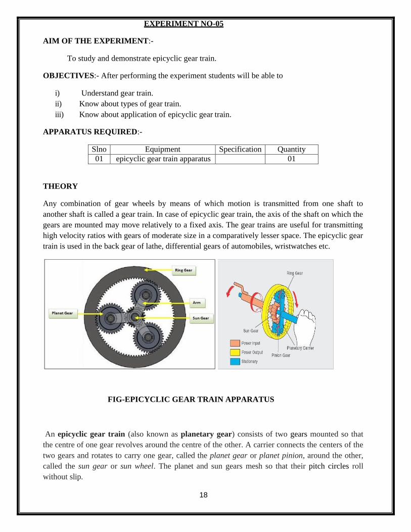
FIG-EPICYCLIC GEAR TRAIN APPARATUS
An epicyclic gear train (also known as planetary gear) consists of two gears mounted so that
the centre of one gear revolves around the centre of the other. A carrier connects the centers of the
two gears and rotates to carry one gear, called the planet gear or planet pinion, around the other,
called the sun gear or sun wheel. The planet and sun gears mesh so that their pitch circles roll
without slip.
19
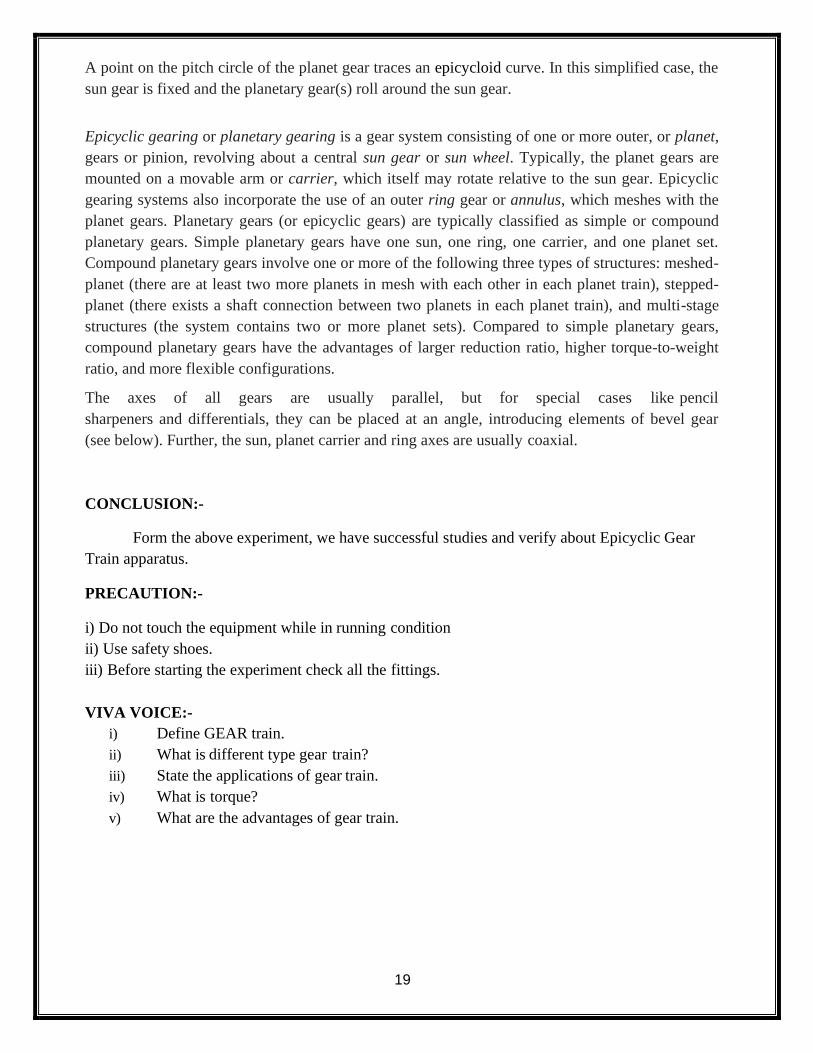
A point on the pitch circle of the planet gear traces an epicycloid curve. In this simplified case, the
sun gear is fixed and the planetary gear(s) roll around the sun gear.
Epicyclic gearing or planetary gearing is a gear system consisting of one or more outer, or planet,
gears or pinion, revolving about a central sun gear or sun wheel. Typically, the planet gears are
mounted on a movable arm or carrier, which itself may rotate relative to the sun gear. Epicyclic
gearing systems also incorporate the use of an outer ring gear or annulus, which meshes with the
planet gears. Planetary gears (or epicyclic gears) are typically classified as simple or compound
planetary gears. Simple planetary gears have one sun, one ring, one carrier, and one planet set.
Compound planetary gears involve one or more of the following three types of structures: meshed-
planet (there are at least two more planets in mesh with each other in each planet train), stepped-
planet (there exists a shaft connection between two planets in each planet train), and multi-stage
structures (the system contains two or more planet sets). Compared to simple planetary gears,
compound planetary gears have the advantages of larger reduction ratio, higher torque-to-weight
ratio, and more flexible configurations.
The axes of all gears are usually parallel, but for special cases like pencil
sharpeners and differentials, they can be placed at an angle, introducing elements of bevel gear
(see below). Further, the sun, planet carrier and ring axes are usually coaxial.
CONCLUSION:-
Form the above experiment, we have successful studies and verify about Epicyclic Gear
Train apparatus.
PRECAUTION:-
i) Do not touch the equipment while in running condition
ii) Use safety shoes.
iii) Before starting the experiment check all the fittings.
VIVA VOICE:-
i) Define GEAR train.
ii) What is different type gear train?
iii) State the applications of gear train.
iv) What is torque?
v) What are the advantages of gear train.
20
EXPERIMENT NO-06
AIM OF THE EXPERIMENT:-
Determination of thickness of M.S.Flat to an accuracy of 0.02mm using Vernier caliper.
OBJECTIVE:- After performing this experiment students will be able to
i) Know about the measuring instrument.
ii) Measure the thickness ,length, internal diameter, outer diameter and depth .
iii) Know about least count.
APPARATUS REQUIRED:-
SL.NO Name of the Items Specification Quantity
01. Vernier caliper 150mm, LC 0.02 01
02. M.S Flat (50x50x6)mm (70x50x5)mm
02.
THEORY:-
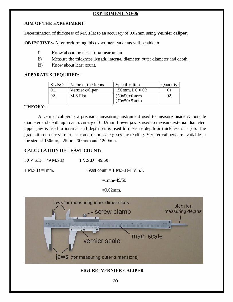
A vernier caliper is a precision measuring instrument used to measure inside & outside
diameter and depth up to an accuracy of 0.02mm. Lower jaw is used to measure external diameter,
upper jaw is used to internal and depth bar is used to measure depth or thickness of a job. The
graduation on the vernier scale and main scale gives the reading. Vernier calipers are available in
the size of 150mm, 225mm, 900mm and 1200mm.
CALCULATION OF LEAST COUNT:-
50 V.S.D = 49 M.S.D 1 V.S.D =49/50
1 M.S.D =1mm. Least count = 1 M.S.D-1 V.S.D
=1mm-49/50
=0.02mm.
FIGURE: VERNIER CALIPER
21
PROCEDURE:-
1. At first we took the vernier caliper and adjusted it correctly So that the vernier scale zero and
main scale zero coincide with each other.
2. Then we calculate the least count of the vernier scale.
3. Then we took the M.S Flat and kept it inside the external diameter measuring jaw.
4. We took the main scale reading and vernier scale division.
5. Then we noted down in the table.
6. In this way we take 5 observations.
TABULATION :-( All units are in mm)
SL.NO. M.S.R in mm
V.S.D L.C in mm
V.S.R(V.S.D x L.C)
M.S.R +V.S.R
Reading in mm
Remarks
01 0.02
02 0.02
03 0.02
04 0.02
05 0.02
CONCLUSION:-
From the above experiment we successfully measured the dimensions of ground M.S Flat
up to an accuracy of 0.02 mm.
PRECAUTION:-
i) Handle the instrument carefully.
ii) Do not give excess pressure while measuring.
VIVA VOICE:-
i) What is least count?
ii) State different parts of vernier caliper.
iii) What is the material of vernier caliper?
iv) How we can measure the thickness of a plate?
22
EXPERIMENT NO-07
AIM OF THE EXPERIMENT:-
Determination of diameter of a cylindrical component to an accuracy of 0.01mm using
micrometer.
OBJECTIVE:- After performing this experiment students will be able to
i) Know about the measuring instrument.
ii) Measure the outer diameter of a given cylindrical specimen.
iii) Know about least count.
APPARATUS REQUIRED:-
SL.NO Name of the Items Specification Quantity
01 Outside Micrometer (0.25mm) 01
02 Cylindrical component
20x50mm 02
THEORY:-
A micrometer is a precision measuring instrument used to measure a job generally with an
accuracy of 0.01mm. Micrometers used to take the outside measurements are knownas outside
micrometer. The frame is the main part in which all other parts of the micrometers are attached to
it. The datum line and graduations are marked on barrel. Graduations are also marked on
beveledsurface of the thimble. One end of spindle and anvil are measuring faces. To lock the
spindle at desired position lock nut is used, the ratchet stop gives uniform pressure between
measuring surfaces.
Least count:-
The distance moved by the spindle during one rotation of thimble is 0.5mm.Movement of one
division of the
Thimble = 0.5 x 1/50 = 0.01mm.
23
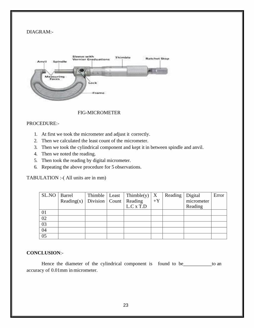
DIAGRAM:-
FIG-MICROMETER
PROCEDURE:-
1. At first we took the micrometer and adjust it correctly.
2. Then we calculated the least count of the micrometer.
3. Then we took the cylindrical component and kept it in between spindle and anvil.
4. Then we noted the reading.
5. Then took the reading by digital micrometer.
6. Repeating the above procedure for 5 observations.
TABULATION :-( All units are in mm)
SL.NO Barrel
Reading(x)
Thimble
Division
Least
Count
Thimble(y)
Reading L.C x T.D
X +Y
Reading Digital
micrometer Reading
Error
01
02
03
04
05
CONCLUSION:-
Hence the diameter of the cylindrical component is found to be to an
accuracy of 0.01mm in micrometer.

24
PRECAUTION:-
i) Handle the instrument carefully.
ii) Do not give excess pressure while measuring.
VIVA VOICE:-
i) What is least count?
ii) State different parts of micrometer.
iii) What is the material of micrometer?
iv) How we can measure the diameter of a plate?
25
EXPERIMENT NO-08
AIM OF THE EXPERIMENT:-
Determination of the heights of gauge blocks or parallel bars to an accuracy of 0.02mm
using venire height gauge .
OBJECTIVE:-:- After performing this experiment students will be able to
i) Know about the measuring instrument.
ii) Measure the height of the given specimen.
iii) Know about least count.
APPARATUS REQUIRED:-
SL.NO Name of the Items Specification Quantity
01 Vernier height gauge 300mm 01
03 Parallel bars 100 x50 x 6mm 02`
04 Gauge blocks 1 boxes(81 pc s) 1 box
THEORY:-
A height gauge is a measuring device used either for determining the height of objects, or for
marking of items to be worked on. These measuring tools are used in metalworking or metrology
to either set or measure vertical distances; the pointer is sharpened to allow it to act as
a scriber and assist in marking out work pieces. Height gauges may also be used to measure the
height of an object by using the underside of the scriber as the datum. The datum may be
permanently fixed or the height gauge may have provision to adjust the scale, this is done by
sliding the scale vertically along the body of the height gauge by turning a fine feed screw at the
top of the gauge; then with the scriber set to the same level as the base, the scale can be matched to
it. This adjustment allows different scribers or probes to be used, as well as adjusting for any
errors in a damaged or re-sharpened probe.
CALCULATION OF LEAST COUNT:-
50 V.S.D = 49 M.S.D 1 V.S.D =49/50
1 M.S.D =1mm. Least count = 1 M.S.D-1 V.S.D
=1mm-49/50
=0.02mm.
26
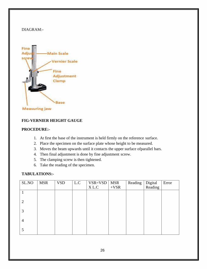
DIAGRAM:-
FIG-VERNIER HEIGHT GAUGE
PROCEDURE:-
1. At first the base of the instrument is held firmly on the reference surface.
2. Place the specimen on the surface plate whose height to be measured.
3. Moves the beam upwards until it contacts the upper surface ofparallel bars.
4. Then final adjustment is done by fine adjustment screw.
5. The clamping screw is then tightened.
6. Take the reading of the specimen.
TABULATIONS:-
SL.NO MSR VSD L.C VSR=VSD X L.C
MSR +VSR
Reading Digital Reading
Error
1
2
3
4
5
27
CONCLUSION:-
Hence the height of gauge blocks or parallel bars are found to be by vernier
height gauge .
PRECAUTION:-
i) Handle the instrument carefully.
ii) Do not give excess pressure while measuring.
VIVA VOICE:-
i) What is least count?
ii) State different parts of vernier height gauge.
iii) What is the material of vernier height gauge?
iv) How to measure height of a specimen using vernier height gauge?
28
EXPERIMENT NO-09
AIM OF THE EXPERIMENT:-
Determination the thickness of M.S. Plates using slip gauges.
OBJECTIVE:- After performing this experiment students will be able to
i) Know about the measuring instrument.
ii) Measure the height of the given specimen.
APPARATUS REQUIRED:-
SL.NO Name of the Items Specification Quantity
01 M.S Plates (100 x 50 x06)mm 02
02 Slip gauge (0-40), 30mmx 9mm size
1 box
03 Surface Plate 300 x 300 01
04 Vernier height
gauge
300mm 01
THEORY:-
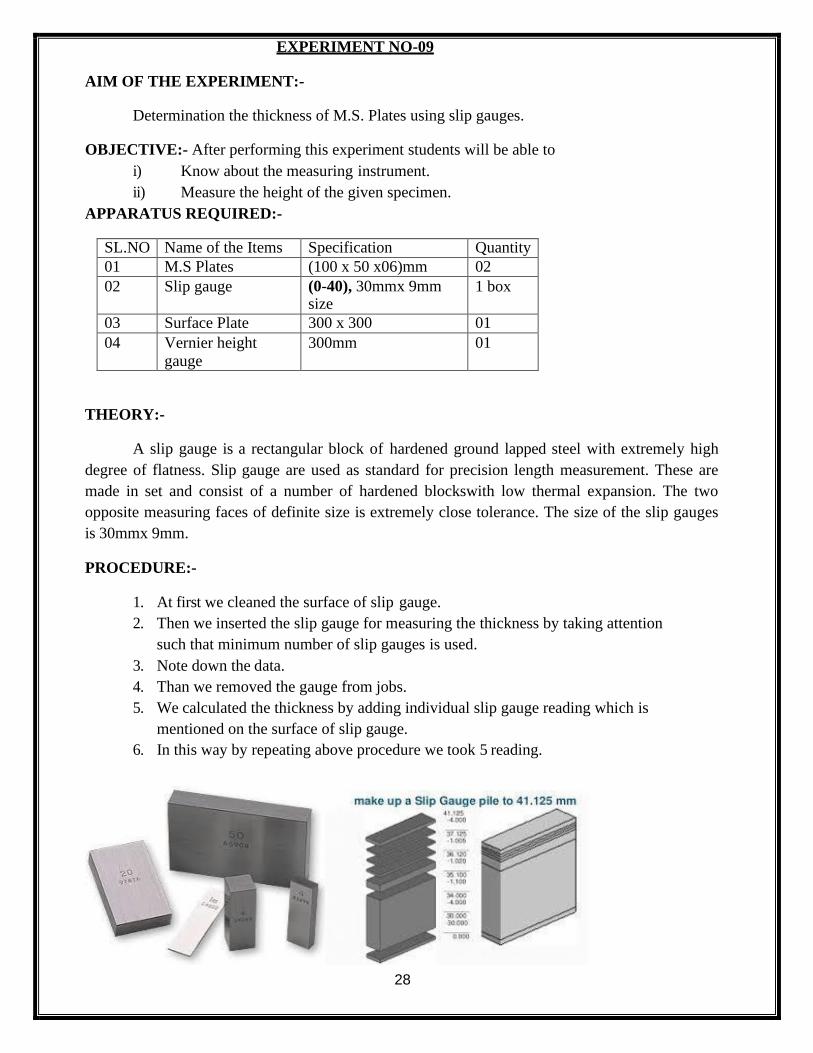
A slip gauge is a rectangular block of hardened ground lapped steel with extremely high
degree of flatness. Slip gauge are used as standard for precision length measurement. These are
made in set and consist of a number of hardened blockswith low thermal expansion. The two
opposite measuring faces of definite size is extremely close tolerance. The size of the slip gauges
is 30mmx 9mm.
PROCEDURE:-
1. At first we cleaned the surface of slip gauge.
2. Then we inserted the slip gauge for measuring the thickness by taking attention
such that minimum number of slip gauges is used.
3. Note down the data.
4. Than we removed the gauge from jobs.
5. We calculated the thickness by adding individual slip gauge reading which is
mentioned on the surface of slip gauge.
6. In this way by repeating above procedure we took 5 reading.
29
TABULATION:-
SL .NO Select
the slip
gauges
Select
the
1stslip
Select 2nd
Select 3rd
Select 4th Total
reading
Average
reading
01
02
03
04
05
CONCLUSION:-
From the above experiment we find the thickness of M.S plate by using the range of slip gauges.
PRECAUTION:-
i) Handle the instrument carefully.
ii) Do not give excess pressure while measuring.
iii) Keep your table clean.
VIVA VOICE:-
i) What is slip gauge?
ii) What is the application of slip gauge?
iii) What is the material of slip gauge?
iv) State procedure of measurement using slip gauges.
30
EXPERIMENT NO-10
AIM OF THE EXPERIMENT:-
To determine the angle of machined surfaces of components using sin bar with slip gauges.
OBJECTIVE:- After performing this experiment students will be able to
i) Know about the measuring instrument.
ii) Measure the angle of the given specimen using sine bar.
APPARATUS REQUIRED:-
SL.NO Name of the Items Specification Quantity
01 One machined surface in any angle
01
02 Sine bar 200mm 01
03 Slip gauge box (0-45) pcs 01 set
04 Sprit level 01
THEORY:-
SINE BAR:-
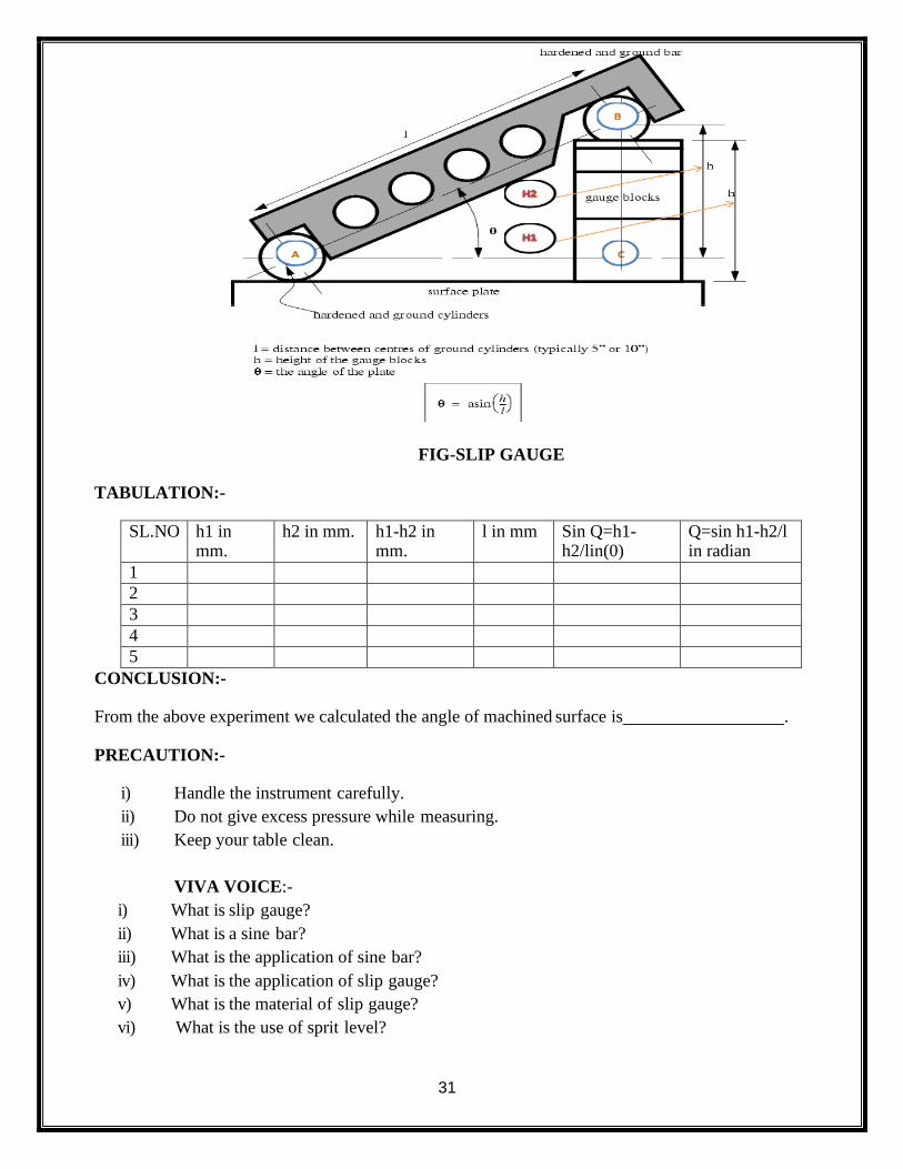
It is based on the sin angle of the right angle triangle. That’s why it is known as sin bar. Sin
of an angle of a right angled triangle its perpendicular is divided by hypotenuses. Sine bars are
available in size of 5”, 10” and 20” and its accuracy of grade-“A” is 0.00001” per inch for grade-
“B” is 0.002” per inch.
SLIP GAUGES:-
For measuring and checking the size of such jobs slip gauge are used. There are generally
made of tool steel, tungsten carbide etc. Their gauging surface is quite plain. When two pieces of
gauges are kept properly one over the other, they stick to each other due to presence of wring film
over them which prevent sliding of gauge blocks over one another, so it gives high accuracy
measurement as the gap between the slip gauges is negligible.
PROCEDURE:-
1. At first keep the sine bar on the machined surface.
2. Check the surface using spirit level.
3. Keep the slip gauges below the ends of the sine bar as per requirement.
4. From that compute h1, h2 height and length L of sine bar and put it in the
following table.
31
FIG-SLIP GAUGE
TABULATION:-
SL.NO h1 in mm.
h2 in mm. h1-h2 in mm.
l in mm Sin Q=h1- h2/lin(0)
Q=sin h1-h2/l in radian
1
2
3
4
5
CONCLUSION:-
From the above experiment we calculated the angle of machined surface is .
PRECAUTION:-
i) Handle the instrument carefully.
ii) Do not give excess pressure while measuring.
iii) Keep your table clean.
VIVA VOICE:-
i) What is slip gauge?
ii) What is a sine bar?
iii) What is the application of sine bar?
iv) What is the application of slip gauge?
v) What is the material of slip gauge?
vi) What is the use of sprit level?