Embed Size (px)
Citation preview

DESCRIPTION, INSTALLATION, OPERATION AND MAINTENANCE MANUAL
REMOTE SWITCH 453-0023, MODULE INTERFACE 453-1101
AND BUZZER 452-6505 INSTALLATION
570-0023 Rev. G
Artex Products / ACR Electronics, Inc.
Artex Products / ACR Electronics, Inc. 5757 Ravenswood Road, Fort Lauderdale, Florida USA
Phone 954-981-3333, Fax 954-983-5087 www.acrartex.com

Artex Products / ACR Electronics, Inc. 570-0023 Rev. G
Page 2 of 33
Notices
1. This document discloses subject matter in which ACR Electronics, Inc. has proprietary rights. Neither receipt nor possession thereof confers or transfers any right to reproduce or disclose the document, any part thereof, any information therein, or any physical article or device, or practice any method or process except by written permission from or written agreement with ACR Electronics, Inc.
2. This manual is subject to regular updates and changes.
3. Cell Warning:
131-0001 CELL WARNING: DO NOT RECHARGE, SHORT-CIRCUIT, DISASSEMBLE, DEFORM, HEAT OR PLACE NEAR A DIRECT FLAME

Artex Products / ACR Electronics, Inc. 570-0023 Rev. G
Page 3 of 33
List of Affected Pages
PAGE # DATE REASON FOR CHANGE
TITLE 04/16/09 DCN 2818, 2929, 3418, 3459, ECO 15051, ECO 15431
1 04/16/09 DCN 2819, 2825, 3418, ECO 15051
2 04/16/09 DCN 2818, 2929, 3418, ECO 15051
3 04/16/09 DCN 2818, 2929, 3068, 3418, 3459, ECO 15051, ECO
15431
4 04/16/09 DCN 2818, 2929, 3068, 3418, ECO 15051
5 04/16/09 DCN 3068, 3418, 3459, ECO 15051, ECO 15431
6 04/16/09 DCN 3068, 3418, ECO 15051
7 04/16/09 DCN 3068, 3418, ECO 15051
8 04/16/09 DCN 2819, 2825, 3068, 3418, ECO 15051
9 04/16/09 DCN 3068, 3418, 3459, ECO 15051
10 04/16/09 DCN 3068, 3418, 3459, ECO 15051
11 04/16/09 DCN 3068, 3418, 3459, ECO 15051, ECO 15431
12 04/16/09 DCN 3068, 3418, 3459, ECO 15051, ECO 15431
13 04/16/09 DCN 3068, 3418, 3459, ECO 15051
14 04/16/09 DCN 3068, 3418, 3459, ECO 15051
15 04/16/09 DCN 3068, 3418, 3459, ECO 15051
16 04/16/09 DCN 3068, 3418, ECO 15051
17 04/16/09 DCN 3068, 3418, ECO 15051
18 04/16/09 DCN 3068, 3418, 3459, ECO 15051
19 04/16/09 DCN 3068, 3418, ECO 15051
20 04/16/09 DCN 3068, 3418, 3459, ECO 15051, ECO 15431
21 04/16/09 DCN 3068, 3418, ECO 15051, ECO 15431
22 04/16/09 DCN 3068, 3418, ECO 15051
23 04/16/09 DCN 3068, 3418, ECO 15051
24 04/16/09 DCN 3068, 3418, ECO 15051
25 04/16/09 DCN 3068, 3418, ECO 15051
26 04/16/09 DCN 3068, 3418, ECO 15051
27 04/16/09 DCN 3068, 3418, ECO 15051
28 04/16/09 DCN 3068, 3418, ECO 15051
29 04/16/09 DCN 3068, 3418, ECO 15051

Artex Products / ACR Electronics, Inc. 570-0023 Rev. G
Page 4 of 33
PAGE # DATE REASON FOR CHANGE
30 04/16/09 DCN 3068, 3418, ECO 15051
31 04/16/09 DCN 3418, ECO 15051
32 04/16/09 DCN 3418, ECO 15051
33 04/16/09 DCN 3418, ECO 15051

Artex Products / ACR Electronics, Inc. 570-0023 Rev. G
Page 5 of 33
Revision History
REVISION ENGINEERING CHANGE ORDER DATE
- RELEASE 06/02/06
A DCN 2819, 2825 11/01/06
B DCN 2818, 2929 01/29/07
C DCN 3068 02/14/08
D DCN 3418 04/16/09
E DCN 3459 07/27/09
F ECO 15051 4/30/12
G ECO 15431 7/25/13

Artex Products / ACR Electronics, Inc. 570-0023 Rev. G
Page 6 of 33
Table of Contents
1. INTRODUCTION ................................................................................................8
2. PARTS LIST .......................................................................................................8
3. WIRING PIN OUT .............................................................................................9
4. HARNESS ....................................................................................................... 10
5. WIRING DIAGRAMS ...................................................................................... 11
6. 453-0023 REMOTE SWITCH INSTALLATION ................................................. 13
6.1 AMERI-KING AND ACK INSTALLATION RETROFIT .............................................................. 13
6.2 TYPICAL INSTALLATION .............................................................................................. 15
6.3 PANEL CUTOUT INSTRUCTIONS .................................................................................... 16
7. INSTALLATION .............................................................................................. 18
7.1 INSTRUCTIONS......................................................................................................... 18
8. 453-1101 MODULE INTERFACE INSTALLATION ............................................ 20
8.1 INSTRUCTIONS......................................................................................................... 20
9. 453-1101 MODULE INTERFACE AND 452-6505 BUZZER WIRING ................ 21
9.1 INSTRUCTIONS......................................................................................................... 21
10. REMOTE SWITCH CELL REPLACEMENT .......................................................... 21
10.1 CELL SHELF LIFE ...................................................................................................... 21
10.2 MATING COVER REMOVAL ........................................................................................... 22
10.3 CELL REPLACEMENT FROM CELL HOLDER WITH STAND ALONE SPRING .................................... 22
10.4 CELL REPLACEMENT FROM CELL HOLDER WITH BUILT-IN SPRING .......................................... 26
10.5 MATING COVER INSTALLATION ..................................................................................... 29
10.6 CELL DISPOSAL INSTRUCTIONS .................................................................................... 30
11. TROUBLESHOOTING GUIDE .......................................................................... 30
12. SPECIFICATIONS ........................................................................................... 31
12.1 COMPONENTS DIMENSIONS ......................................................................................... 31
12.3 ENVIRONMENTAL CATEGORIES ..................................................................................... 32
13. INDEX ............................................................................................................ 33
Artex Products / ACR Electronics, Inc. 570-0023 Rev. G
Page 7 of 33
List of Figures
Figure 1: Wiring Diagram for Shielded Cable (Composite Aircraft) ........................................................ 11
Figure 2: Wiring Diagram for Unshielded Telephone Cable ................................................................... 11
Figure 3: Wiring Diagram for Shielded Cable (Metal Aircraft) ................................................................ 12
Figure 4: Wiring Diagram for Unshielded Telephone Cable (Metal Aircraft) ............................................ 12
Figure 5: Labels 591-0003 & 591-3029 ............................................................................................... 16
Figure 6: Panel Cutout Dimensions ..................................................................................................... 16
Figure 7: Harness to Remote Switch Connection ................................................................................. 18
Figure 8: Remote Switch Orientation .................................................................................................. 18
Figure 9: Remote switch wire tensile load release ............................................................................... 19
Figure 10: Module Interface to ELT Connection ................................................................................... 20
Figure 11: Spring Configuration .......................................................................................................... 22
Figure 12: Conical Spring ................................................................................................................... 23
Figure 13: Conical Spring Installation ................................................................................................. 23
Figure 14: Cell Holder Wires .............................................................................................................. 24
Figure 15: Ground Wire ..................................................................................................................... 25
Figure 16: Cell Installation ................................................................................................................. 26
Figure 17: Spring Installation ............................................................................................................. 26
Figure 18: Spring Fit .......................................................................................................................... 27
Figure 19: Cell Holder Wires .............................................................................................................. 27
Figure 20: Ground Wire ..................................................................................................................... 28
Figure 21: Mating Cover Installation ................................................................................................... 29
Figure 22: Retaining Screws Installation ............................................................................................. 29
Figure 23: 453-0023 Remote Switch ................................................................................................... 31
Figure 24: 453-1101 Module Interface ................................................................................................ 31

Artex Products / ACR Electronics, Inc. 570-0023 Rev. G
Page 8 of 33
1. INTRODUCTION
This manual contains detailed information to install the self-powered remote switch 453-0023, module interface 453-1101, and the buzzer 452-6505. In addition, these instructions highlight the methodology to replace the cell in the remote switch. This manual is not intended to be an installation for the ELT system.
Use this manual in conjunction with any of Artex ME406 series ELT manuals.
2. PARTS LIST
The following parts should be included with the 455-0023 and 455-7420 Pack Lists. Please contact ACR Electronics, Inc., if shortages are found.
QUANTITY PART NUMBER DESCRIPTION
455-0023 Pack List, Self-Powered Remote Switch
4 ea. 209-0002 Screw, 4-40 X 1/2, SOC, SS, BLK
4 ea. 241-0400 HEX Nut, 4-40 Reduced Dim.
1 ea. 453-0023 Remote Switch, Self-Powered Assembly
1 ea. 570-0023 Manual, Remote Switch 453-0023, Module Interface 453-1101 and Buzzer 452-6505 Installation
1 ea. 591-0003 Label, 453-0023 Remote Switch Horizontal
1 ea. 591-0036 Label, Cell Replacement Warning
1 ea. 591-3029 Label, 453-0023 Remote Switch
QUANTITY PART NUMBER DESCRIPTION
455-7420 Pack List, ME406 Install Kit
4 ea. 201-0810 Screw, PHP 8-32 x 5/8 SS
4 ea. 241-0832 Nut, HEX 8-32 x 1/4 SS
4 ea. 246-0008 Washer, Flat, SS .036”-.045" THK 2 ea. 850-0814 Sealant Strip, D-sub Connector

Artex Products / ACR Electronics, Inc. 570-0023 Rev. G
Page 9 of 33
3. WIRING PIN OUT
The following information highlights the pin out of the remote switch and module interface.
Remote Switch Back View
VIEW PIN # SIGNAL DESCRIPTION
PIN 2
2 Light
3 External On
4 Reset 1
5 Reset 2
Module Interface Front View
VIEW PIN # SIGNAL DESCRIPTION
2 Light
5 G-Switch Loop
6 Reset 1
7 Ground
8 Horn Power
12 G-Switch Loop
13 Reset 2
14 External ON
Module Interface Back View
VIEW PIN # SIGNAL DESCRIPTION
PIN 2
2 Light
3 External On
4 Reset 1
5 Reset 2

Artex Products / ACR Electronics, Inc. 570-0023 Rev. G
Page 10 of 33
4. HARNESS
Due to the large array of configurations possible, ACR Electronics, Inc. does not provide a harness or RJ11 plugs (telephone connector) as part of the installation of the ELT. Accordingly, it is the responsibility of the installer to manufacture a harness or ensure that the existing harness is adequate for the installation.
The harness must be manufactured following the cross-wired configuration mentioned in Subsection 6.2.
NOTE: Refer to Subsection 6.1 for Ameri-King and ACK retrofit installations.
Artex recommends using a shielded cable to prevent signals related to power frequency, audio frequency and electrical transients generated from on-board equipments from interfering with the ELT operation.
Although it might be appropriate to use a telephone line (minimum UL flammability rating VW-1) in some instances, each installation is different and should be evaluated on a case by case basis. Accordingly, it is the responsibility of the ELT installer to ensure that the installations follow FAA regulations such as but not limited to Advisory Circular 43.13.
Refer to the installation section of any of the ME406 series manuals for ELT related information.

Artex Products / ACR Electronics, Inc. 570-0023 Rev. G
Page 11 of 33
5. WIRING DIAGRAMS
Refer to the following wiring diagrams to connect the remote switch 453-0023, module interface 453-1101, and buzzer 452-6505 to the ME406 series ELT.
NOTE: For Ameri-King or ACK ELT retrofit application, refer to Subsection 6.1.
Figures 1 and 2 apply to composite aircraft, whereas Figures 3 and 4 apply to metal aircraft.
2
3
4
5
5
4
3
2
1
2
3
#26 AWG RED WIRE
#26 AWG BLACK WIRE
#26 AWG BLUE WIRE
HARNESS
4-CONDUCTOR CABLE
(SHIELDED)
REMOTE SWITCH
453-0023
2
3
4
5
LIGHT
EXTERNAL ON
RESET 1
RESET 2
2
BRAID
2
BRAIDMO
DU
LE I
NTER
FACE
453-1
101
2
3
4
5
3 GPS
2
HORN
452-6505
1
EMERGENCY LOCATOR
TRANSMITTER (ELT)
LIGHT
EXTERNAL ON
RESET 1
RESET 2
HORN POWER
GROUND
2
14
6
13
8
7
ANTENNA
Figure 1: Wiring Diagram for Shielded Cable (Composite Aircraft)
2
3
4
5
5
4
3
2
1
2
3
#26 AWG RED WIRE
#26 AWG BLACK WIRE
#26 AWG BLUE WIRE
HARNESS
4-CONDUCTOR TELEPHONE CABLE
(UNSHIELDED)
REMOTE SWITCH
453-0023
2
3
4
5
LIGHT
EXTERNAL ON
RESET 1
RESET 2
2
2
MO
DU
LE I
NTER
FACE
453-1
101
2
3
4
5
3 GPS
2
HORN
452-6505
1
EMERGENCY LOCATOR
TRANSMITTER (ELT)
LIGHT
EXTERNAL ON
RESET 1
RESET 2
HORN POWER
GROUND
2
14
6
13
8
7
ANTENNA
ADDITIONAL WIRE
(ACROSS AIRCRAFT)
Figure 2: Wiring Diagram for Unshielded Telephone Cable (Composite Aircraft)
CAP & STOW
CAP & STOW

Artex Products / ACR Electronics, Inc. 570-0023 Rev. G
Page 12 of 33
Figures 3 and 4 apply to metal aircraft.
2
3
4
5
5
4
3
2
1
2
3
#26 AWG RED WIRE
#26 AWG BLACK WIRE
#26 AWG BLUE WIRE
HARNESS
4-CONDUCTOR CABLE
(SHIELDED)
REMOTE SWITCH
453-0023
2
3
4
5
LIGHT
EXTERNAL ON
RESET 1
RESET 2
2
2
MO
DU
LE I
NTERFACE
453-1
101
2
3
4
5
3 GPS
2
HORN
452-6505
1
EMERGENCY LOCATOR
TRANSMITTER (ELT)
LIGHT
EXTERNAL ON
RESET 1
RESET 2
HORN POWER
GROUND
2
14
6
13
8
7
ANTENNA
Figure 3: Wiring Diagram for Shielded Cable (Metal Aircraft)
2
3
4
5
5
4
3
2
1
2
3
#26 AWG RED WIRE
#26 AWG BLACK WIRE
#26 AWG BLUE WIRE
HARNESS
4-CONDUCTOR TELEPHONE CABLE
(UNSHIELDED)
REMOTE SWITCH
453-0023
2
3
4
5
LIGHT
EXTERNAL ON
RESET 1
RESET 2
2
2
MO
DU
LE I
NTERFACE
453-1
101
2
3
4
5
3 GPS
2
HORN
452-6505
1
EMERGENCY LOCATOR
TRANSMITTER (ELT)
LIGHT
EXTERNAL ON
RESET 1
RESET 2
HORN POWER
GROUND
2
14
6
13
8
7
ANTENNA
Figure 4: Wiring Diagram for Unshielded Telephone Cable (Metal Aircraft)
CAP & STOW
CAP & STOW

Artex Products / ACR Electronics, Inc. 570-0023 Rev. G
Page 13 of 33
6. 453-0023 REMOTE SWITCH INSTALLATION
6.1 Ameri-King and ACK Installation Retrofit
Ameri-King retrofit:
The remote switch 453-0023 and ME406 series ELT cannot be used in conjunction with the Ameri-King interconnecting cable unless extender 611-0018 is connected directly with the Ameri-King cable. This 611-0018 extender is provided as part of the ELT installation pack list or can be ordered as line item.
The 611-0019 flat cable can be discarded since it is intended for ACK retrofit.
AMERI-KING CABLE
(INSIDE AIRCRAFT)EXTENDER
611-0018
EXTENDER
611-0018

Artex Products / ACR Electronics, Inc. 570-0023 Rev. G
Page 14 of 33
ACK retrofit:
The remote switch 453-0023 and ME406 series ELT cannot be used in conjunction with the ACK interconnecting cable unless Flat Cable 611-0019 is connected directly with the ACK cable.
This 611-0019 cable is provided as part of the ELT installation pack list or can be ordered as line item. The cable is installed on the ELT side.
The 611-0018 extender can be discarded since it intended for Ameri-King ELT retrofit.
FLAT CABLE
611-0019ACK CABLE
(INSIDE AIRCRAFT)
FLAT CABLE
611-0019
611-0019 Wiring
C1 C2
2 5
3 4
4 3
5 2
C1
C2
PIN 2

Artex Products / ACR Electronics, Inc. 570-0023 Rev. G
Page 15 of 33
6.2 Typical Installation
6.2.1 Due to the large array of configurations possible, ACR Electronics, Inc. does not provide a harness or RJ11 plugs (telephone connector) as part of the installation of the ELT.
6.2.2 The harness must be manufactured following the cross-wired configuration shown below.
NOTE: Refer to Subsection 6.1 for ACK and Ameri-King retrofits.
Wiring
C1 C2
2 5
3 4
4 3
5 2
C1
C2
PIN 2

Artex Products / ACR Electronics, Inc. 570-0023 Rev. G
Page 16 of 33
6.3 Panel Cutout Instructions
6.3.1 Select a mounting location where the remote switch can be seen from the pilot’s seated location, easily be reached by the pilot, out of direct sunlight, and can accommodate the remote switch and the label. Depending on the remote switch orientation on the control panel, choose the appropriate label and discard the other one. Label 591-0003 and label 591-3029 are provided in the 455-0023 pack list.
Figure 5: Labels 591-0003 & 591-3029
6.3.2 Create a cutout in the panel for the remote switch according to the minimum dimensions specified below and drill four 1/8” diameter holes. The dimensions apply to both 591-0003 and 591-3029 labels. Adjust the hole-pattern appropriately on the panel depending on the orientation of the remote switch.
NOTE: For Ameri-King retrofit applications, use the existing mounting holes since the face plate of the remote switch is designed to accommodate that hole-pattern.
Tolerance: +.020, -.000
Figure 6: Panel Cutout Dimensions

Artex Products / ACR Electronics, Inc. 570-0023 Rev. G
Page 17 of 33
6.3.3 Clean the application surface area thoroughly prior to applying label 591-0003 or 591-3029.
6.3.4 Remove the paper backing from the label and line up the label over the cutout.
6.3.5 Press firmly and evenly over the label to produce maximum adhesion.
6.3.6 Trim the label with an Exacto knife if it partially covers the mounting holes.

Artex Products / ACR Electronics, Inc. 570-0023 Rev. G
Page 18 of 33
7. INSTALLATION
7.1 Instructions
7.1.1 Feed the modular jack connector from the harness through the panel cutout.
7.1.2 Plug the modular jack connector to the remote switch.
Figure 7: Harness to Remote Switch Connection
7.1.3 Slide the remote switch and the harness inside the cutout following the orientation shown below.
7.1.4 Secure the remote switch using the hardware provided in the 455-0023 pack list. Use a 1/16 hex socket for the nuts and a small Phillips screwdriver for the screws. The torque on the screws is 4.0 Lb-in (± 0.5 Lb-in).
Figure 8: Remote Switch Orientation

Artex Products / ACR Electronics, Inc. 570-0023 Rev. G
Page 19 of 33
7.1.5 Fasten the ground wire along the harness within one inch of the remote switch using a tie cable.
NOTE: The ground wire should have enough slack to prevent tensile load.
Figure 9: Remote switch wire tensile load release
(Panel not shown)
7.1.6 Connect the remote switch 26 AWG ground wire according to the wiring diagrams highlighted in section 5 using a ring or a fork terminal quick disconnect.
NOTE: Secure an additional wire to the ground wire with a butt slice to extend the length if necessary.
7.1.7 Fasten the harness to the aircraft. Ensure that the harness has enough slack to prevent tensile load on the modular jack connector of the remote switch.
7.1.8 Plug the modular jack connector of the harness to the module interface 453-1101 if it is already installed.
7.1.9 Refer to the Transmitter Test section of the ME406 series ELT manuals to check the operation of the complete connection to the ELT.
7.1.10 Apply Cell Replacement Warning label 591-0036 from kit 455-0023 inside the aircraft’s logbook. The intent of the label is to remind the pilot to change the cell inside the remote switch every five years or sooner depending on usage.
7.1.11 Enter the date, installer’s initials and whether the ELT passed or failed into the aircraft’s logbook.

Artex Products / ACR Electronics, Inc. 570-0023 Rev. G
Page 20 of 33
8. 453-1101 MODULE INTERFACE INSTALLATION
8.1 Instructions
8.1.1 Place the two sealing strips 850-0814 provided in the 455-7420 install kit into the ELT 15-pin D-sub connector.
8.1.2 Insert the module interface 453-1101 into the ELT D-sub and secure it in place using the two thumbscrews. The torque on the thumbscrews is 4 to 5 Lb-in.
Figure 10: Module Interface to ELT Connection
(Red Wire - Horn Power, Black Wire - A/C Ground, Blue Wire – Cap & Stow)
8.1.3 Fasten the three wires along the harness within one inch of the module interface using cable ties.
NOTE: The length of the wires between the end of the module and the first cable tie should have enough slack to provide strain relief.
8.1.4 Fasten the harness to the aircraft. Ensure that the harness has enough slack to prevent tensile load on the modular jack connector of the module interface.
8.1.5 Plug the modular jack connector of the harness to the remote switch 453-0023 if it is already installed.
8.1.6 Refer to the Transmitter Test section of the ME406 series ELT manuals to check the operation of the complete connection to the ELT.
8.1.7 Enter the date, installer’s initials and whether the ELT passed or failed into the aircraft’s logbook.
Artex Products / ACR Electronics, Inc. 570-0023 Rev. G
Page 21 of 33
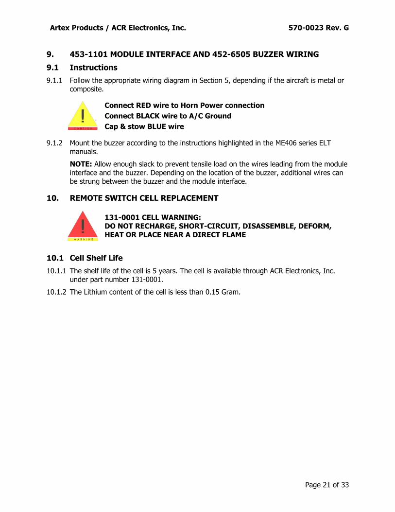
9. 453-1101 MODULE INTERFACE AND 452-6505 BUZZER WIRING
9.1 Instructions
9.1.1 Follow the appropriate wiring diagram in Section 5, depending if the aircraft is metal or composite.
Connect RED wire to Horn Power connection
Connect BLACK wire to A/C Ground
Cap & stow BLUE wire
9.1.2 Mount the buzzer according to the instructions highlighted in the ME406 series ELT manuals.
NOTE: Allow enough slack to prevent tensile load on the wires leading from the module interface and the buzzer. Depending on the location of the buzzer, additional wires can be strung between the buzzer and the module interface.
10. REMOTE SWITCH CELL REPLACEMENT
131-0001 CELL WARNING: DO NOT RECHARGE, SHORT-CIRCUIT, DISASSEMBLE, DEFORM, HEAT OR PLACE NEAR A DIRECT FLAME
10.1 Cell Shelf Life
10.1.1 The shelf life of the cell is 5 years. The cell is available through ACR Electronics, Inc. under part number 131-0001.
10.1.2 The Lithium content of the cell is less than 0.15 Gram.

Artex Products / ACR Electronics, Inc. 570-0023 Rev. G
Page 22 of 33
10.2 Mating Cover Removal
10.2.1 Remove the four retaining nuts and screws securing the remote switch 453-0023 to the panel.
10.2.2 Slide the remote switch from the panel.
10.2.3 Cut the tie cables securing the ground wire to the harness.
10.2.4 Disconnect the modular jack connector of the harness from the remote switch.
10.2.5 Remove the four retaining screws from the remote switch to access the cell compartment.
10.2.6 Remove the protective cover opposite of the product label.
10.3 Cell Replacement from Cell Holder with Stand Alone Spring
10.3.1 At this point, two options are available depending on the manufacturing date of the remote switch:
The remote switch was manufactured with an individual spring unattached to the cell holder.
Accordingly, proceed with the following instructions.
This newest version of the remote switch was manufactured with a built-in spring
permanently attached to the cell holder. Accordingly, proceed to section 10.4.
Figure 11: Spring Configuration
Spring Spring

Artex Products / ACR Electronics, Inc. 570-0023 Rev. G
Page 23 of 33
10.3.2 Carefully remove the cell 131-0001 from the plastic cell holder and keep the conical spring.
Figure 12: Conical Spring
10.3.3 Dispose of the cell according to the instructions specified in section 10.6.
10.3.4 Carefully slide the replacement cell 131-0001 inside the plastic cell holder following the polarity mentioned inside the holder and on the cell, or by matching the positive (+) end of the cell to the red wire side of the holder.
10.3.5 Install the conical spring between the positive side of the cell and the cell holder.
10.3.6 Push the cell against the conical spring.
Figure 13: Conical Spring Installation
Spring

Artex Products / ACR Electronics, Inc. 570-0023 Rev. G
Page 24 of 33
10.3.7 Gently route the black and red wires from the plastic cell holder away from the leads of the rocker switch if necessary.
Figure 14: Cell Holder Wires
Wires away from PCB

Artex Products / ACR Electronics, Inc. 570-0023 Rev. G
Page 25 of 33
10.3.8 Position the ground wire (black) along the side of the plastic cell holder and away from the screw boss.
Figure 15: Ground Wire
10.3.9 Refer to Subsection 10.5 to install the mating cover.
Black Wire
Screw boss

Artex Products / ACR Electronics, Inc. 570-0023 Rev. G
Page 26 of 33
10.4 Cell Replacement from Cell Holder with Built-in Spring
10.4.1 Carefully remove the cell 131-0001 from the plastic cell holder.
10.4.2 Dispose of the cell according to the instructions specified in Subsection 10.6.
10.4.3 Carefully slide the negative end of the replacement cell 131-0001 inside the plastic cell holder following the polarity mentioned inside the holder and on the cell, or by matching the positive (+) end of the cell to the red wire side of the holder.
Figure 16: Cell Installation
10.4.4 Pull the built-in spring away from the end of the cell using tweezers and slide the cell inside the holder.
Figure 17: Spring Installation

Artex Products / ACR Electronics, Inc. 570-0023 Rev. G
Page 27 of 33
10.4.5 Release the spring and ensure that it is properly pushing against the end of the cell.
Figure 18: Spring Fit
10.4.6 Gently route the black and red wires from the plastic cell holder away from the leads of the rocker switch if necessary.
Figure 19: Cell Holder Wires
Wires away from PCB

Artex Products / ACR Electronics, Inc. 570-0023 Rev. G
Page 28 of 33
10.4.7 Position the ground wire (black) along the side of the plastic cell holder and away from the screw boss.
Figure 20: Ground Wire
Black Wire
Screw boss

Artex Products / ACR Electronics, Inc. 570-0023 Rev. G
Page 29 of 33
10.5 Mating Cover Installation
10.5.1 Install the mating cover to the assembly by matching the cutouts according to the different components.
10.5.2 Ensure that the 26 AWG ground wire is properly fed through the notch of the mating cover and is not pinched by the screw boss.
Figure 21: Mating Cover Installation
10.5.3 Secure the covers together using the retaining screws previously removed. The torque on the screws is 2.0 Lb-in (+0 Lb-in, - 0.5 Lb-in).
Figure 22: Retaining Screws Installation
10.5.4 Refer to section 7 to install the remote switch back on the panel.
10.5.5 Refer to the Transmitter Test section of the ME406 series ELT manuals to check the operation of the complete connection to the ELT.
10.5.6 Apply Cell Replacement Warning label 591-0036 from kit 455-0023 inside the aircraft’s logbook. The intent of the label is to remind the pilot to change the cell inside the remote switch every five years or sooner depending on usage.
10.5.7 Enter the date, installer’s initials and whether the ELT passed or failed into the aircraft logbook.
Mating cover

Artex Products / ACR Electronics, Inc. 570-0023 Rev. G
Page 30 of 33
10.6 Cell Disposal Instructions
Lithium batteries are best disposed of as a non-hazardous waste when fully or mostly discharged. The Federal Environmental Protection Agency (EPA) governed by the Resource Conservation and Recovery Act (RCRA) do not list or exempt Lithium as a hazardous waste. However, if waste lithium batteries are still fully charged or only partially discharged, they can be considered a reactive hazardous waste because of the significant amounts of un-reacted or unconsumed lithium remaining in the spent battery. The batteries must be neutralized through an approved secondary treatment facility prior to disposal as a hazardous waste (as required by the U.S. Land Ban Restrictions for the hazardous and Solid Waste Amendments of 1984.) Secondary treatment centers receive these batteries as manifested hazardous waste under code "D003 - reactive". Button cells are exempt because they contain so little lithium and therefore can be disposed of in the normal municipal waste stream.
11. TROUBLESHOOTING GUIDE
Refer to the ME406 series ELT manuals for flash error codes during Self-Test.
SYMPTOM LIKELY CAUSE ACTION
LED of the remote switch is not flashing when either the ELT or the remote switch is turn ON.
The voltage of the cell is below 3.3 volts.
Replace the cell.
The harness is not secured to the remote switch.
Check that the modular jack is fully inserted inside the back of the remote switch.
The remote switch ground wire is not connected to the module interface ground.
For a metallic aircraft, check the resistance between the remote switch and the module interface (10 Ω min.)
The module interface is not connected to the ELT.
Check the connection.
Cell is not installed properly. Check the polarity of the cell with respect to the plastic cell holder.
The wiring configuration is incorrect.
Refer to Section 5.

Artex Products / ACR Electronics, Inc. 570-0023 Rev. G
Page 31 of 33
12. SPECIFICATIONS
12.1 Components Dimensions
The following dimensions are displayed in [millimeters] and inches.
Figure 23: 453-0023 Remote Switch
Figure 24: 453-1101 Module Interface
12.2 Components Weight
PART NUMBER DESCRIPTION WEIGHT
452-6505 Buzzer, Piezo .34 oz (9.64 gr.) Max.
453-0023 Remote Switch, Self-Powered 1.30 oz (36.85 gr.)
Max.
453-1101 Module Interface, ELT to Remote Switch
1 oz (28.35 gr.) Max.
The buzzer 452-6505 is included with the ELT Pack List.

Artex Products / ACR Electronics, Inc. 570-0023 Rev. G
Page 32 of 33
12.3 Environmental Categories
DO-160D Environmental categories for nameplates:
Remote switch 453-0023:
DO-160D Env. Cat. F1XCAA[204]XWXXXXXXXXA[XXX]X[XXXX]XXX
Module interface 453-1101:
DO-160D Env. Cat D2XBA[204][204]XWXXXXXXXXA[XXX]X[XXXX]XXX

Artex Products / ACR Electronics, Inc. 570-0023 Rev. G
Page 33 of 33
13. INDEX
4
455-0023 Pack List, 8 455-7420 Pack List, 8
5
591-0003 Label, 16 591-3029 Label, 16
6
611-0018 Extender, 13 611-0019 Cable, 14
A
ACK retrofit, 14 Advisory Circular 43.13-2A, 10 Ameri-King retrofit, 13
B
Buzzer 452-6505, 11
C
Cell Disposal Instructions, 30 Cell Shelf Life, 21 Cell Warning, 21
D
Dimensions, Components, 31
E
Environmental Categories, 32
G
Ground Wire, Remote Switch, 19
H
Harness, 10
I
Installation, Module Interface, 20, 21 Installation, Remote Switch, 13
L
Label 591-0003, 16 Label 591-0036, 19, 29 Label 591-3029, 16 LED, 18, 30 List of Figures, 7
M
Module Interface Installation, 20, 21
O
Orientation, Remote Switch, 18, 19
P
Panel Cutout Dimensions, 16 Panel Cutout Instructions, 16 Parts List, 8
R
Remote Switch Installation, 13 Replacement, Cell Remote Switch, 21
S
Shelf Life, Cell, 21 Specifications, 31
T
Telephone Line, 10 Troubleshooting Guide, 30
W
Weight, Components, 31 Wiring Diagram for shielded cable (Composite
Aircraft), 11 Wiring Diagram for telephone line (Composite
Aircraft), 11 Wiring Diagram for telephone line (Metallic
Aircraft), 12