Embed Size (px)
Citation preview

Defence Standard 00-970 Part 9 Issue 13 Date: 13 July 2015
_______________________________________
Design and Airworthiness Requirements for Service Aircraft
Part 9: Remotely Piloted Air Systems _______________________________________

DEF STAN 00-970 PART 9/13
2
REVISION NOTE This standard is raised to Issue 13 to update text. Major revisions to this Part of the Defence Standard are noted in Part 0, Section 6. HISTORICAL RECORD This standard supersedes the following: Defence Standard (Def Stan) 00-970 Part 9 Issue 12 dated 30 January 2015. Design and Airworthiness Requirements for Service Aircraft – UAV Systems Defence Standard (Def Stan) 00-970 Part 9 Issue 11 dated 11 July 2014. Defence Standard (Def Stan) 00-970 Part 9 Issue 10 dated 10 January 2014. Defence Standard (Def Stan) 00-970 Part 9 Issue 9 dated 05 July 2013. Defence Standard (Def Stan) 00-970 Part 9 Issue 8 dated 06 July 2011. Defence Standard (Def Stan) 00-970 Part 9 Issue 7 dated 31 October 2011. Defence Standard (Def Stan) 00-970 Part 9 Issue 6 dated 31 January 2011. Defence Standard (Def Stan) 00-970 Part 9 Issue 5 dated 31 March 2009. Defence Standard (Def Stan) 00-970 Part 9 Issue 4 Amendment 1 dated 07 October 2008 Defence Standard (Def Stan) 00-970 Part 9 Issue 4 dated 27 January 2006 Defence Standard (Def Stan) 00-970 Issue 3 dated October 2003 Defence Standard (Def Stan) 00-970 Issue 2 dated 1 December 1999 Defence Standard (Def Stan) 00-970 Issue 1 dated 12 December 1983 Aviation Publication (AvP) 970 dated 1959 Design Requirements for Service Aircraft Air Publication (AP) 970 2nd Edition dated 1924 Handbook of Strength Calculations Handbook (HB) 806 1st Edition dated 1918 Handbook of Strength Calculations.

DEF STAN 00-970 PART 9/13
3
DESIGN AND AIRWORTHINESS REQUIREMENTS FOR SERVICE AIRCRAFT
PART 9 - REMOTELY PILOTED AIR SYSTEMS
PREFACE
(a) This Part of the Defence Standard provides requirements for Airworthiness and Design Certification for the design, development and testing of Remotely Piloted Air Systems (RPAS) for flight UK Military operation. The requirements stated herein shall be applied by the Ministry of Defence (MOD) and the contractor as agreed and defined in the contract. (b) This document has been produced on behalf of the Military Aviation Authority Executive Board (MEB) by the Military Aviation Authority (MAA), MAA Technical Group, MOD Abbey Wood. (c) The appropriate Parts of this document are to be used, when called up in the Contract, for all future designs, and whenever practicable for amendments to existing designs. If any difficulty arises which prevents application of this document, DSA-MAA-Cert-ADS1 shall be informed so that a remedy may be sought: e-mail: [email protected] (d) Where the requirements of other Standards are considered applicable, the relevant chapters and/or clauses are cross-referenced by this Part of the Defence Standard. (e) Any enquiries regarding this document in relation to an invitation to tender or a contract in which it is incorporated are to be addressed to the relevant MOD Project Team Leader (PTL) named in the invitation to tender or contract. (f) Please address any enquiries regarding this standard, whether in relation to an invitation to tender or to a contract in which it is incorporated, to the responsible technical or supervising authority named in the invitation to tender or contract. (g) Compliance with this Defence Standard shall not in itself relieve any person from any legal obligations imposed upon them. Project Leaders are to ensure that equipment procured from outside of the European Union (EU) meets or exceeds those legal requirements mandated within the EU (See MAA 01 Chapter 1 and the RA1000 Series). (h) This standard has been devised solely for the use of the Ministry of Defence (MOD) and its contractors in the execution of contracts for the MOD. To the extent permitted by law, the MOD hereby excludes all liability whatsoever and howsoever arising (including, but without limitation, liability resulting from negligence) for any loss or damage however caused when the standard is used for any other purpose.

DEF STAN 00-970 PART 9/13
4
CONTENTS
Description Page No Preface 3 Contents 4 SECTION ONE - GENERAL REQUIREMENTS
1.1 Introduction and Purpose 6 1.2 Applicability and Scope 7 1.3 Warning 10 1.4 Definitions 10 1.5 Normative References 10 SECTION 2 FIXED WING - AIRWORTHINESS CODE AND ACCEPTABLE MEANS OF COMPLIANCE (AMC) (150 – 20,000 kg) Subpart A General 12 Subpart B UAV Flight 13 Subpart C UAV Structure 18 Subpart D UAV Design and Construction 23 Subpart E UAV Powerplant 29 Subpart F Equipment 37 Subpart G Operating Limitations and Information 44 Subpart H Command and Control Data Link 46 Subpart I UAV Control Station 48 Appendix C Basic Landing Conditions 55 Appendix D Wheel spin-up Loads 55 Appendix F Test Procedure for Self-Extinguishing Materials 55 Appendix G Instructions for Continued Airworthiness 55 SECTION 3 ROTARY WING - AIRWORTHINESS CODE AND ACCEPTABLE MEANS OF COMPLIANCE (AMC) (150 – 3175 kg) Subpart A General 56 Subpart B UAV Flight 57 Subpart C UAV Structure 60 Subpart D UAV Design and Construction 63 Subpart E UAV Powerplant 70 Subpart F Equipment 77 Subpart G Operating Limitations and Information 84 Subpart H Command and Control Data Link 86 Subpart I UAV Control Station 88 Appendix A Instructions for Continued Airworthiness 95 Appendix B Not Applicable 95 Appendix C Icing Certification 95 Appendix D HIRF Environments and Equipment HIRF Test Levels 95 Appendix E Not Applicable 95 Appendix F Test Procedure for Self-Extinguishing Materials 95

DEF STAN 00-970 PART 9/13
5
SECTION 4 LIGHT FIXED WING - AIRWORTHINESS CODE AND ACCEPTABLE MEANS OF COMPLIANCE (AMC) (Sub 150 kg) Scope 96 Introduction 96 Type Design Airworthiness Evidence 96 Source Documents 96 Restricted Certification 96 Requirements 96 ER.1 System Integrity 97 ER.1.1 Structures and Materials 97 ER.1.2 Propulsion 101 ER.1.3 Systems and Equipment 107 ER.1.4 Continued Airworthiness of the UAS 117 ER.2 Airworthiness Aspects of System Operation 118 ER.3 Organisations 123 Annex A Terms and Definitions 125 Annex B Landing Conditions for Conventional Landing Gear Configurations (Where
Applicable) 125 Annex C Spark and Compression Ignition Reciprocating Engines 125 Annex D Electric Engines 125 Annex E Turbine Engines 125 Annex F Propellers 125 Annex G Hazard Reference System 125 Annex H Stability and Response Assessment Guidance 125 Annex I The Safety Management Plan 125 Annex J Guidelines for Airworthiness Requirements Applicable to UA below the 66J Impact
Energy 125 SECTION 5 LIGHT VERTICAL TAKE OFF AND LANDING (VTOL) - AIRWORTHINESS CODE AND ACCEPTABLE MEANS OF COMPLIANCE (AMC) (Sub 150 Kg) (To be published)

DEF STAN 00-970 PART 9/13 SECTION 1
6
DESIGN AND AIRWORTHINESS REQUIREMENTS FOR SERVICE AIRCRAFT
PART 9: REMOTELY PILOTED AIR SYSTEMS
SECTION 1 - GENERAL REQUIREMENTS
1.1 INTRODUCTION AND PURPOSE 1.1.1 General (a) In 1991, the Ministry of Defence (MOD), looking at its responsibilities for airworthiness, decided that it was necessary to define the design and airworthiness requirements for Unmanned Air Vehicle (UAV) Systems. This responsibility was delegated to the Joint Technical Requirements Committee (JTRC), chaired by ADRP, who tasked Sub-Committee 31 with defining these requirements. (b) Sub-Committee 31, now known as the UAV System Sub Committee, (which comprises of members from both MOD and Industry) held its inaugural meeting in March 1992, when its terms of reference (TOR) and structure were set out and later agreed by the JTRC. (c) With the internal reorganization and rationalization of ADRP, it was agreed in 1996 that responsibility for UAV Systems should come under the Joint Airworthiness Committee (JAC). Due to the close relationship between UAV System design requirements and those for manned aircraft, it was agreed with the Directorate of Standardization that UAV System design requirements should form part of Defence Standard 00-970. (d) Responsibility for sponsorship, technical authorship of Defence Standard 00-970 Part 9 lies with the Military Aviation Authority (MAA) – MAA Certification Group. 1.1.2 The Defence Standard (a) Part 9 of Defence Standard 00-970 details Design and Airworthiness Requirements for Remotely Piloted Air Systems. (b) Reference should also be made to the other parts of Defence Standard 00-970 and to Defence Standard 07-85 which, although relating to the design requirements for manned aircraft and guided weapons respectively, can also be applicable to RPAS. (c) This document builds on the Society of British Aerospace Companies document, “Guide to the Procurement, Design and Operation of UAV Systems”. (d) It is intended that this Part of the Defence Standard should be of use to MOD Project Team Leaders (PTL) and designers for any RPAS procurement. The complexity of the RPAS is determined by use and application. The MOD PTL should therefore identify the clauses of this Part of the Defence Standard to be applied to the RPAS under consideration, noting its intended use, capability requirements and cost constraints. (e) Where information is contained in other authoritative documents, these documents will be quoted and shall be used. This will ensure that only current authorised and agreed requirements and procedures are used. As well as reducing the overall size of this document, this action will also ensure that amendments are kept to a minimum.

DEF STAN 00-970 PART 9/13 SECTION 1
7
1.1.3 Aim (a) This Part of the Defence Standard has been written to provide Design and Airworthiness guidance for both the contractor/designer and the MOD Project Team. It is not intended that it should restrict design organisations and designers in their endeavour to provide materiel fit for purpose. It will be the responsibility of the MOD PTL to decide whether to quote the whole or parts of this document in the contract specification. This Defence Standard or parts of this Standard become mandatory only when called up in the contract specification (RA 5000 series refers). (b) This Defence Standard is structured on the basis of a MOD PT contracting a prime contractor/RPAS Design organisation for a RPAS. Where contractual arrangements differ from this, the MOD PTL shall ensure that the requirements of this standard are correctly apportioned to the responsible parties. An example is where major items, such as the powerplant or sensor suite, are GFE. 1.2 APPLICABILITY AND SCOPE 1.2.1 General (a) This Part of the Defence Standard has been written specifically to cover the design and airworthiness requirements for RPAS as defined in Clause 1.4 (b) This Part of the Defence Standard does not differentiate between target drones, surveillance, stealth or combat RPAS that are, or have been, designed from the outset for operation without an on-board pilot. Neither does it give mandatory requirements for the method of control or launch to be used. These aspects shall be identified and covered in the appropriate RPAS Requirements Specification. (c) The operational role of the RPAS will determine its complexity and the safe guards needed to ensure that it is capable of performing its defined tasks safely. 1.2.2 Scope (a) The mandatory requirements set out in this standard are those basic requirements needed for the design and development of airworthy RPAS for all three UK Armed Services.
(b) In addition to the mandatory requirements set out in this document, the airworthiness standards set out in the following are also mandated: NATO STANAG 4671 Unmanned Aerial Vehicles System Airworthiness Requirements (USAR) Edition 2; NATO STANAG 4702 Rotary Wing Unmanned Aerial Systems Airworthiness Requirements; NATO STANAG 4703 Light Unmanned Aircraft Systems Airworthiness Requirements; NATO STANAG 4746 Unmanned Aerial Vehicle System Airworthiness Requirements for Light Vertical Take Off and Landing Aircraft (To be published); Supplemented by the following UK national reservations. NB the terms RPAS, RPAV as used in Def Stan 00-970 and UAS, UA as used in the NATO STANAG are interchangeable.

DEF STAN 00-970 PART 9/13 SECTION 1
8
(c) UK national reservations STANAG 4671:
(1) Amend USAR paragraph U50. Insert new paragraph U50(c) Demonstrate that there is adequate margin (e.g. 15%, to be agreed with the Certifying Authority) between Vs and Vmin
FCS (i.e. to take account of gust) and that Vmin FCS is robust. (2) Insert after USAR paragraph 201(ii). iii) VminDEMO to be equivalent to VminFCS (3) Amend USAR paragraph AMC.1309(b). Insert the additional sentence at (5)(c)(i). more severe criteria may be needed for large aircraft;
Insert the additional sub-paragraphs after (5)(c)(1). (i) For large aircraft from 5,700kg up to 20,000kg MTOW (with the exception of propeller-driven twin-engine RPAS, refer paragraph ii). At RPAV system level, the combination of all Catastrophic failure conditions is characterised by an occurrence of 10-6 per flying hour or less (with the calculation method subject to Certifying Authority agreement). (ii) For propeller-driven twin-engine RPAS from 8,618kg up to 20,000kg MTOW, at RPAV system level, the combination of all Catastrophic failure conditions is characterised by an occurrence of 10-6 per flying hour or less (with the calculation method subject to Certifying Authority agreement).
(d) UK national reservations STANAG 4702:
(1) With respect to (WRT) paragraph 631 Bird Strike: The energy requirement derived from CS-29 associated with a 1 kg bird is considered disproportionate for a sub-3175kg rotorcraft. Therefore requirement UK.631a has been created.
(2) WRT paragraph 833: CS 27.833 (& CS29.833) specifically relates to Combustion heaters, as defined in SAE Aeronautical Standard AS143B, which must be approved in accordance with TSO-C20. TSOs do not exist for other heater types. See FAR AC 29-2C. A combustion heater requirement is considered unnecessary for this RPAS standard however if such a system is deemed necessary for a specific RPAS this could be added as a Special Condition. Requirement 833 has therefore been marked as N/A (Consistent with requirement 859).
(3) WRT paragraph 1353: Sub-paragraphs (f) and (g) are specifically applicable to Nickel-Cadmium batteries, but may also be relevant to other battery technologies. Civil Certification Specifications do not apply these rules to Lead Acid batteries. Applicability of Subparts (f) and (g) to new technology batteries/charge devices (for example Lithium-Ion and super-caps) should be considered by the applicant and incorporated into the Type Certification Basis through application of Special Conditions. Re-instate 'Nickel-Cadmium' to USAR RW.1353 (f) and (g)
(f) Each nickel cadmium battery….. (g) Nickel cadmium battery installations….

DEF STAN 00-970 PART 9/13 SECTION 1
9
(4) WRT paragraph U1607: the requirement does not require growth potential for the DATA link. The following paragraph is to be added to the requirement:
(f) The capacity of the data link must be determined to provide an acceptable margin under the highest usage condition expected throughout the Service life of the platform.
(e) UK national reservations STANAG 4703:
(1) With respect to (WRT) Introduction paragraph 3 Type design airworthiness evidence: Add the following "as agreed with the Certifying Authority" to read; The Applicant should create comprehensive arguments, supported by a body of evidence, to demonstrate how the mandatory Essential Requirements for Airworthiness have been met and to provide confidence in the airworthiness of the UA type design. The evidence could consist of one or more forms of the following types as agreed with the Certifying Authority. (2) WRT ER.1.2.5 and UL.19 The requirement does not consider the routing of fuel pipes in relation to electrical cables, junction boxes or equipment: Add the following as UL.19.10 UL.19.10 The fuel system design must take into account the following:
a. Possible sources of ignition including electrical faults, over-heating of equipment and the malfunction of protective devices. b. Possible sources and paths of fluid leakage and means of detecting leakage. c. Flammability characteristics of fluids, including effects of any combustible or absorbing materials.
(3) WRT ER.1.3.2 and UL.24 the Aw ER should cover the static and pitot pressure sources: Add the following as a new paragraph for UL.24. UL.24.7 Pitot & Static systems where utilised must be designed and installed so that:
a. Sensors with static air case connections are vented to the outside atmosphere. b. Pitot tubes and static ports shall be located and mounted in such a manner as to avoid airflow turbulence and other pressure distorting effects. Variations from actual pressure are known and taken into account within the systems using pitot or static information. c. Chafing of tubing and excessive distortion is avoided and that the materials used are suitable for the purpose. d. A suitable system (e.g. pitot heating) is required for clearance in icing conditions. e. A proof test must be carried out to demonstrate the integrity and accuracy of the system.
(4) WRT ER.1.3.2 and UL.24 does not state requirement for power generation & distribution: Add the following as a new paragraph for UL.24. UL24.9 The power generation system must be:
a. Adequate to meet the largest peak load expected and be demonstrated to have adequate margin above the maximum peak load to operate flight safety critical systems.

DEF STAN 00-970 PART 9/13 SECTION 1
10
b. Have a warning system for the indication of failure to provide minimum acceptable output. c. Have characteristics in line with STANAG 3456.
f. UK national reservations STANAG 4746: (To be Published) g. In the event that there are discrepancies in the airworthiness requirements contained in the NATO STANAG and Def Stan 00-970 Part 9 then the requirements in Def Stan 00-970 are to take precedence. However, in such circumstances DSA-MAA-Cert-ADS1 is to be advised. h. Unmanned dirigibles – Until the release of an EASA Certification Specification compliance with the requirements of either of the documents referenced within Part 15 for the design of dirigibles will be considered by the authority; however the requirements specific to RPAS (e.g. DATA Link, GCS) within this document are mandated. i. At present this standard does not cover the following: Aircraft (with a previously issued Design Certificate and a Military Aircraft Release) that have been converted from a manned to an unmanned role. 1.3 WARNING The Ministry of Defence (MOD), like its contractors, is subject to both United Kingdom and European laws regarding Health and Safety at Work. Many Defence Standards set out processes and procedures that could be injurious to health if adequate precautions are not taken. Adherence to those processes and procedures in no way absolves users from complying with legal requirements relating to Health and Safety at Work. Note: Where a design to the requirements of this document may result in an adverse environmental impact the MOD PTL shall be advised. 1.4 Definitions 1.4.1. Definitions are contained in Part 0 of this standard. 1.5 Normative References 1.5.1 The publications shown in Part 0 are referred to in the text of this standard. Note: Def Stan’s can be downloaded free of charge from the DStan web site by visiting http://dstan.uwh.diif.r.mil.uk for those with rli access or https://www.dstan.mod.uk for all other users. All referenced standards were correct at the time of publication of this standard (see 1.5.2, 1.5.3 and 1.5.4 below for further guidance), if you are having difficulty obtaining any referenced standard please contact the DStan Helpdesk in the first instance.
DEF STAN 00-970 PART 9/13 SECTION 1
11
1.5.2 Reference in this Standard to any normative references means in any Invitation to Tender or contract the edition and all amendments current at the date of such tender or contract unless a specific edition is indicated. Care should be taken when referring out to specific portions of other standards to ensure that they remain easily identifiable where subsequent amendments and supersession’s might be made. For some standards the most recent editions shall always apply due to safety and regulatory requirements. 1.5.3 In consideration of the above clause, users shall be fully aware of the issue, amendment status and application of all normative references, particularly when forming part of an Invitation to Tender or contract. Correct application of standards is as defined in the ITT or contract. 1.5.4 DStan can advise regarding where to obtain normative referenced documents. Requests for such information can be made to the DStan Helpdesk. Details of how to contact the helpdesk are shown on the outside rear cover of Defence Standards.
DEF STAN 00-970 PART 9/13 SECTION 2
12
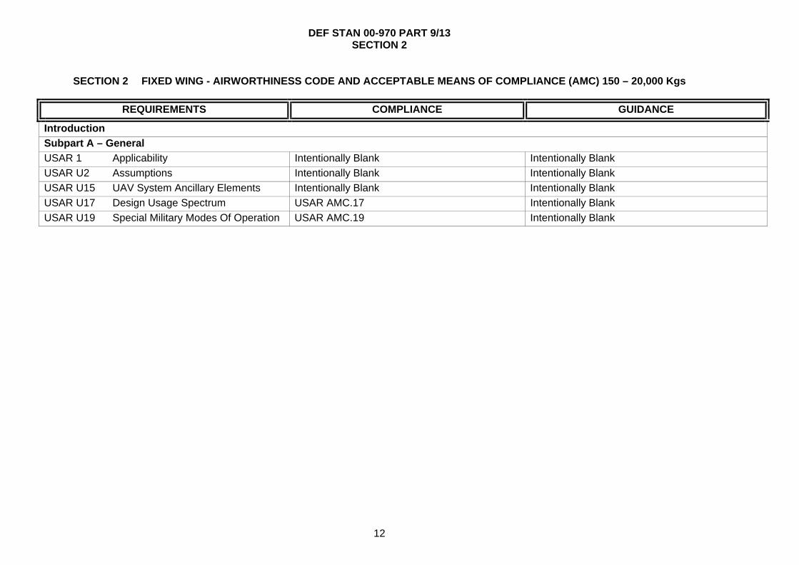
SECTION 2 FIXED WING - AIRWORTHINESS CODE AND ACCEPTABLE MEANS OF COMPLIANCE (AMC) 150 – 20,000 Kgs
REQUIREMENTS COMPLIANCE GUIDANCE
Introduction
Subpart A – General
USAR 1 Applicability Intentionally Blank Intentionally Blank
USAR U2 Assumptions Intentionally Blank Intentionally Blank
USAR U15 UAV System Ancillary Elements Intentionally Blank Intentionally Blank
USAR U17 Design Usage Spectrum USAR AMC.17 Intentionally Blank
USAR U19 Special Military Modes Of Operation USAR AMC.19 Intentionally Blank

DEF STAN 00-970 PART 9/13 SECTION 2
13
REQUIREMENTS COMPLIANCE GUIDANCE
Subpart B - UAV Flight
General
USAR 21 Proof Of Compliance USAR AMC.21 Intentionally Blank
UK FW.21a Range Safety Interfacing - Planning, justification and conduct of range flights shall be carried out to the satisfaction of the Range Safety Authority.
A range safety/trials documentation set shall be produced which addresses both the safe execution of flight trials and the ability to achieve trial objectives.
Intentionally Blank
UK FW.21b Range requirements shall be identified early in the design life-cycle and agreed with the MOD (PTL). Note: this is likely to be an iterative process and will involve clarification and refinement of range requirements.
Intentionally Blank The design of the RPAS should make provision for range safety and trials requirements. These may include safety justification, safety traces, installation of an independent flight termination system, provision (equipment or procedural) for sense and avoid, The ability for a representative of the Range Safety Authority to have immediate sanction over aspects of the RPAV flight. Appropriate warnings (audible and visible) on the air vehicle and/or in the control station of imminent air vehicle recovery. Possible items of equipment include homing beacon, radar reflector, range radar transponder, IFF transponder, TCAS II, ATC voice relay or an appropriate means to allow the range control station to independently monitor the position and/or health of the air vehicle.
UK FW.21c Range interfacing shall ensure safe flight in a range area and the recording of the specified required trials data, through the required interfaces onto a common computerised data base.
Hard-wired interfaces shall be designed so as to have minimal impact on reliability and system mass when no range or trial facilities are fitted.
Trials data will include data generated by the system under test, data generated by trials instrumentation controlled by the trials team, data generated by range instrumentation and data generated by GFF for specific trials.
UK FW.21d Equipment introduced to the RPAS for trials purposes only shall be suitable for the trials environment.
Installations shall be designed against the loads predicted for the trial and to ensure safety of flight is not affected.
Due to the variety of equipment that may be fitted, mechanical interfaces may need to be designed to suit specific trials.

DEF STAN 00-970 PART 9/13 SECTION 2
14
REQUIREMENTS COMPLIANCE GUIDANCE
UK FW.21e The RPAS interfaces for range and trial equipment fits shall be designed to the same standards the relevant prime equipment and shall not reduce the safety of the RPAV to unacceptable levels.
A safety assessment of all trials modifications to the RPAS shall be carried out. The installation of trials equipment shall be within the limits called up in the Safety Case for experimental flying.
Intentionally Blank
USAR 23 Load Distribution Limits Intentionally Blank Intentionally Blank
USAR 25 Weights Limits Intentionally Blank Intentionally Blank
USAR 29 Basic Weight And Corresponding Centre of Gravity
Intentionally Blank Intentionally Blank
USAR 31 Removable Ballast Intentionally Blank Intentionally Blank
USAR 33 Propeller Speed And Pitch Limits Intentionally Blank Intentionally Blank
Performance
USAR 45 General Intentionally Blank Intentionally Blank
UK FW.45 Airframes of a specific build standard shall have predictable and repeatable aerodynamic performance.
Intentionally Blank Intentionally Blank
UK FW.45b Air Launch - RPAVs that are to be launched from manned aircraft in flight shall comply with the requirements for weapons carriage and release as stated in Def Stan 00-970, Part 13 Section 3, Clause 3.1
Following release, the airframe shall be capable of predictable and safe transition into controlled flight for the defined launch envelope.
Intentionally Blank
UK FW.45c Hand Launch - The airframe shall meet the ergonomic requirements of the Health and Safety Legislation and Def Stan 00-250 where applicable.
Intentionally Blank Intentionally Blank
UK FW.45d Carousel Launch - The airframe and all its interfaces shall withstand the worst combination of centripetal and tangential accelerations and aerodynamic forces.
Following release, the airframe shall be capable of predictable and safe transition into controlled flight for the defined launch envelope.
Intentionally Blank
USAR 49 Stalling Speed Intentionally Blank Intentionally Blank
USAR U50 Minimum Demonstration Speed Intentionally Blank Intentionally Blank
UK FW.U50a Refer to UK National Reservations in part 1 - 1.2.2.c.(1)
Intentionally Blank Intentionally Blank
DEF STAN 00-970 PART 9/13 SECTION 2
15
REQUIREMENTS COMPLIANCE GUIDANCE
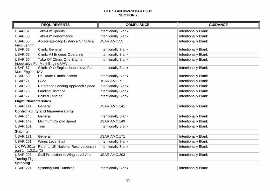
USAR 51 Take-Off Speeds Intentionally Blank Intentionally Blank
USAR 53 Take-Off Performance Intentionally Blank Intentionally Blank
USAR 55 Accelerate-Stop Distance Or Critical Field Length
USAR AMC.55 Intentionally Blank
USAR 63 Climb: General Intentionally Blank Intentionally Blank
USAR 65 Climb: All Engines Operating Intentionally Blank Intentionally Blank
USAR 66 Take-Off Climb: One Engine-Inoperative For Multi-Engine UAV
Intentionally Blank Intentionally Blank
USAR 67 Climb: One Engine-Inoperative For Multi-Engine UAV
Intentionally Blank Intentionally Blank
USAR 69 En-Route Climb/Descent Intentionally Blank Intentionally Blank
USAR 71 Glide USAR AMC.71 Intentionally Blank
USAR 73 Reference Landing Approach Speed Intentionally Blank Intentionally Blank
USAR 75 Landing Distance Intentionally Blank Intentionally Blank
USAR 77 Balked Landing Intentionally Blank Intentionally Blank
Flight Characteristics
USAR 141 General USAR AMC.141 Intentionally Blank
Controllability and Manoeuvrability
USAR 143 General Intentionally Blank Intentionally Blank
USAR 149 Minimum Control Speed USAR AMC.149 Intentionally Blank
USAR 161 Trim Intentionally Blank Intentionally Blank
Stability
USAR 171 General USAR AMC.171 Intentionally Blank
USAR 201 Wings Level Stall Intentionally Blank Intentionally Blank
UK FW.201a Refer to UK National Reservations in part 1 - 1.2.2.c.(2)
Intentionally Blank Intentionally Blank
USAR 203 Stall Protection In Wing Level And Turning Flight
USAR AMC.203 Intentionally Blank
Spinning
USAR 221 Spinning And Tumbling Intentionally Blank Intentionally Blank

DEF STAN 00-970 PART 9/13 SECTION 2
16
REQUIREMENTS COMPLIANCE GUIDANCE
Ground Handling Characteristics
USAR 231 Longitudinal Stability And Control Intentionally Blank Intentionally Blank
USAR 233 Directional Stability And Control Intentionally Blank Intentionally Blank
USAR 235 Operation On Unpaved Surfaces USAR AMC.235 Intentionally Blank
USAR U240 Wet Runway Operations USAR AMC.240 Intentionally Blank
USAR U249 Transportation And Storage Intentionally Blank Intentionally Blank
UK FW.U249a Reliability and Maintainability - Consideration shall be given to comprehensive self-test whilst the sub-systems are packaged for transport or storage.
Intentionally Blank Intentionally Blank
UK FW.U249b The level of transportability of the RPAS shall be defined in the RPAS Requirements Specification.
For all classes of RPAS the transportability guidance set out in Def Stan 00-3 shall be considered, and the resulting design approach agreed with the MOD (PTL)
Consideration should be given to the transportability needs of damaged equipment – especially RPAVs damaged during recovery.
UK FW.U249c Environmental Considerations - Consideration shall be given to the transportability and assembly of ship-based RPAS.
The RPAS shall be able to be transported and assembled on board ship under the range of environmental conditions and sea states as defined in the RPAS Requirements Specification.
Intentionally Blank
UK FW.U249d Containers - Consideration shall be given to use of containers for storage and transport that are standard ISO sizes.
The specifications for containers shall be issued to the MOD (PTL) for agreement.
It may be required that small containers fit within, or within the envelope of larger ISO containers.
UK FW.U249e Containers - Consideration shall be given to the provision of Built in Test capability to enable the container contents to be tested without opening the container.
The provision of container Built in Test shall be agreed with the MOD (PTL) and included in the RPAS Requirements Specification.
Intentionally Blank
UK FW.U249f The air vehicle, its sub-assemblies and components shall be transportable by standard transport facilities.
It shall be possible to divide the RPAV into sub-assemblies so that each sub-assembly when packaged, with such protection as is deemed necessary, meets the requirements of Def Stan 81-41 except for dangerous goods where specific regulations apply.
Intentionally Blank

DEF STAN 00-970 PART 9/13 SECTION 2
17
REQUIREMENTS COMPLIANCE GUIDANCE
Miscellaneous Flight Requirements
USAR 251 Vibration & Buffeting Intentionally Blank Intentionally Blank
USAR 253 High Speed Characteristics Intentionally Blank Intentionally Blank
Catapult Assisted and Rocket Assisted Take-Off UAV
USAR U280 Launch Performance Intentionally Blank Intentionally Blank
USAR U281 Transition To Normal Flight Attitude Intentionally Blank Intentionally Blank
USAR U282 UAV Active Control Intentionally Blank Intentionally Blank
USAR U283 Launch Safety Trace USAR AMC.U283 Intentionally Blank
Parachute Landing System
USAR U290 UAV Performance Before Parachute Landing
Intentionally Blank Intentionally Blank
USAR U291 Parachute Landing Characteristics Intentionally Blank Intentionally Blank
USAR U292 Parachute Landing Performance Intentionally Blank Intentionally Blank
USAR U293 Parachute Landing Safety Trace USAR AMC.293 Intentionally Blank

DEF STAN 00-970 PART 9/13 SECTION 2
18
REQUIREMENTS COMPLIANCE GUIDANCE
Subpart C - UAV Structure
General
USAR 301 Loads USAR AMC.301 Intentionally Blank
USAR 302 Canard Or Tandem Wing Configurations
Intentionally Blank Intentionally Blank
USAR 303 Factor Of Safety Intentionally Blank Intentionally Blank
USAR 304 Structural Performance USAR AMC.304
USAR 305 Strength And Deformation Intentionally Blank Intentionally Blank
USAR 307 Proof Of Structure USAR AMC.307 Intentionally Blank
Flight Loads
USAR 321 General USAR AMC.321 Intentionally Blank
USAR 331 Symmetrical Flight Conditions Intentionally Blank Intentionally Blank
USAR 333 Flight Envelope USAR AMC.333 Intentionally Blank
UK FW.333a The permitted operating envelopes for all given build standards and role configurations of the RPAV shall be declared.
The basic flight envelope shall be defined graphically, without ambiguity, in a recognised format.
The Basic Flight Envelope, conventionally of the form shown in USAR.333, should be expressed in terms of principal parameters such as Equivalent Airspeed (EAS), altitude and normal acceleration (normal load factor as a multiple of G), or any alternative format which more appropriately or more clearly defines those mission requirements of most concern. The effects of RPAV mass properties, role configuration and atmospheric/environmental conditions should be considered.
USAR U334 Flight Envelope Protection Intentionally Blank Intentionally Blank
USAR 335 Design Airspeeds Intentionally Blank Intentionally Blank
USAR 337 Limit Manoeuvring Load Factors Intentionally Blank Intentionally Blank
USAR 341 Gust Load Factors USAR AMC.341 Intentionally Blank
USAR 343 Design Fuel Loads USAR AMC.343 Intentionally Blank
USAR 345 High Lift Devices USAR AMC.345 Intentionally Blank

DEF STAN 00-970 PART 9/13 SECTION 2
19
REQUIREMENTS COMPLIANCE GUIDANCE
USAR 347 Asymmetrical Flight Conditions Intentionally Blank Intentionally Blank
USAR 349 Rolling Conditions Intentionally Blank Intentionally Blank
USAR 351 Yawing Conditions Intentionally Blank Intentionally Blank
USAR 361 Engine Torque Intentionally Blank Intentionally Blank
USAR 363 Sideload On Engine Mount Intentionally Blank Intentionally Blank
USAR 365 Pressurised Compartment Loads Intentionally Blank Intentionally Blank
USAR 367 Asymmetrical Loads Due To Engine Failure
Intentionally Blank Intentionally Blank
USAR 369 Rear Lift Truss Loads Intentionally Blank Intentionally Blank
USAR 371 Gyroscopic And Aerodynamic Loads USAR AMC.371 Intentionally Blank
USAR 373 Speed Control Devices Intentionally Blank Intentionally Blank
Control Surface and System Loads
USAR 391 Control Surface Loads Intentionally Blank Intentionally Blank
USAR 393 Loads Parallel To Hinge Line USAR AMC.393 Intentionally Blank
USAR 395 Control System Loads Intentionally Blank Intentionally Blank
USAR 397 Limit Control Forces And Torques Intentionally Blank Intentionally Blank
USAR 405 Secondary Flight Control Intentionally Blank Intentionally Blank
USAR 407 Trim Tab Effects Intentionally Blank Intentionally Blank
USAR 409 Tabs Intentionally Blank Intentionally Blank
USAR 415 Ground Gust Conditions Intentionally Blank Intentionally Blank
Horizontal Tail Surfaces
USAR 421 Balancing Loads Intentionally Blank Intentionally Blank
USAR 423 Manoeuvring Loads Intentionally Blank Intentionally Blank
USAR 425 Gust Loads Intentionally Blank Intentionally Blank
USAR 427 Asymmetrical Loads Intentionally Blank Intentionally Blank
Vertical Surfaces
USAR 441 Manoeuvring Loads USAR AMC.441 Intentionally Blank
USAR 443 Gust Loads USAR AMC.443 Intentionally Blank

DEF STAN 00-970 PART 9/13 SECTION 2
20
REQUIREMENTS COMPLIANCE GUIDANCE
USAR 445 Outboard Fins Or Winglets Intentionally Blank Intentionally Blank
Ailerons and Special Devices
USAR 455 Ailerons Intentionally Blank Intentionally Blank
USAR 459 Special Devices Intentionally Blank Intentionally Blank
Ground Loads
USAR 471 General USAR AMC.471 Intentionally Blank
UK FW.471a Landing Energy Absorber System - Any on-board Landing Energy Absorber System (LEAS) shall be such as to control the release of absorbed energy to avoid unnecessary damage to the RPAV.
The LEAS shall ensure that the loads which would be transferred to the airframe and payloads on impact with the landing surface are consistent with the structural requirements stated in USAR 301 and any limitations imposed by the payload.
LEAS may include: conventional undercarriage or skids, airbags, retro-rockets, crushable or frangible components, braking parachutes, electromagnetic retardation devices, The system may include devices that are not part of the airframe such as; arrestor wires, nets, impact absorbing material and mid air recovery systems.
UK FW.471b Where the LEAS is independent of the RPAV and is located on the landing surface or elsewhere, the airframe shall be provided with the appropriate means of engagement and retrieval.
The loads applied to the airframe during engagement shall be considered as part of the structural design and subject to the strength factors stated in USAR 613.
Reference should be made to USAR.333 Flight Envelope.
UK FW.471c The turn-round requirements of the LEAS shall be in accordance with the RPAV System Requirement Specification.
Intentionally Blank This may involve recharging gas cylinders, re-packing parachutes, replacing blow-out patches in air-bags or resetting mechanical and electrical systems or the replacement of airframe mounted components.
USAR 473 Ground Load Conditions And Assumptions
Intentionally Blank Intentionally Blank
USAR 477 Landing Gear Arrangement Intentionally Blank Intentionally Blank
USAR 479 Level Landing Conditions Intentionally Blank Intentionally Blank
USAR 481 Tail Down Landing Conditions USAR AMC.481 Intentionally Blank
USAR 483 One Wheel Landing Conditions Intentionally Blank Intentionally Blank
USAR 485 Sideload Conditions Intentionally Blank Intentionally Blank
USAR 493 Braked Roll Conditions Intentionally Blank Intentionally Blank
USAR 497 Supplementary Conditions For Tail Wheels
Intentionally Blank Intentionally Blank

DEF STAN 00-970 PART 9/13 SECTION 2
21
REQUIREMENTS COMPLIANCE GUIDANCE
USAR 499 Supplementary Conditions For Nose Wheels
Intentionally Blank Intentionally Blank
USAR 507 Jacking And Lifting Loads Intentionally Blank Intentionally Blank
USAR 509 Towing Loads Intentionally Blank Intentionally Blank
USAR 511 Ground Load :Asymmetrical Loads On Multiple Wheel Units
Intentionally Blank Intentionally Blank
Fatigue Evaluation
USAR U570 General USAR AMC.570 Intentionally Blank
USAR 572 Metallic Fuselage, Wing, Empennage And Associated Structures
USAR AMC.572 Intentionally Blank
USAR 573 Damage Tolerance And Fatigue Evaluation Of Structure
USAR AMC.573 Intentionally Blank
USAR 575 Inspection And Other Procedures Intentionally Blank Intentionally Blank
Catapult Assisted and Rocket Assisted Take-Off UAV
USAR U585 Launch Load Factor Intentionally Blank Intentionally Blank
USAR U586 Use Of Trolley Or Shuttle Intentionally Blank Intentionally Blank
UK FW.U586a Pressurised gas systems shall be designed to the requirements of Def Stan 00-970 Part 1 Section 6, Clause 6.14, (See also, Section 6 Clause 6.12, BS-4N100:1 , Def Stan 81-24 and BS EN 1803
Intentionally Blank The operating performance and reliability of stored energy catapult systems are particularly susceptible to environmental extremes such as heat, cold and the ingress of moisture or contaminants.
USAR U587 Rocket Assisted Take-Off Intentionally Blank Intentionally Blank
UK FW.U587a Rocket Assisted Takeoff (RATO) - The storage, transportation, handling, testing and operation of the RATO units shall be in undertaken following the safety guidance advice from DOSG.
Any device intended to restrain the air vehicle shall be capable of doing so for the highest possible motor thrust, and should preferably isolate the electrical initiation circuit to the rocket motor.
Design loads for RATO launch systems should take into account the stochastic variation in solid propellant characteristics and the most adverse environmental conditions. RATO launch involves the acceleration of the air vehicle from a support stand or via a short ground run by means of a rocket booster. The booster may be temporarily affixed to the RPAV to enable launch and may be released or jettisoned at the end of burn. Where asymmetric thrust and/or active flight controls during launch are possible, loads induced by

DEF STAN 00-970 PART 9/13 SECTION 2
22
REQUIREMENTS COMPLIANCE GUIDANCE
these systems should be catered for in the design of the RATO Launch system.
UK FW.587b RATO - Any failure of the RATO system shall not result in a hazardous situation, or pose a safety hazard to personnel.
Hazard analysis of the launch system should include: failure to ignite, asymmetric ignition, late ignition and partial thrust.
DOSG should be consulted for guidance.
UK FW.U587c RATO - The Launcher system, platform or personnel shall be protected from the effects of rocket plume impingement at launch and any debris emitting from the rocket motor.
The use of suitable materials, blast shields and safety procedures shall be implemented.
Intentionally Blank
Arrested Landing System
USAR U590 Arresting System USAR AMC.590 Further guidance in Def Stan 00-970 Part 13 Section 3 - 3.6 Arresting Hooks for land-based aeroplanes.
Parachute Landing System
USAR U595 Limit Load Factor USAR AMC.595 Intentionally Blank
USAR U596 UAV Dragging On Ground Intentionally Blank Intentionally Blank
USAR U597 Sacrificial Elements Intentionally Blank Intentionally Blank
USAR U598 Extracting Devices USAR AMC.598 Intentionally Blank
USAR U599 Installation Of The Parachute In The Airframe
Intentionally Blank Intentionally Blank
UK FW.U599a The routing of parachute attachment strops shall be unambiguous.
Instructions for routing of parachute strops shall be marked on the airframe and strops or highlighted in appropriate servicing manuals.
Intentionally Blank
DEF STAN 00-970 PART 9/13 SECTION 2
23
REQUIREMENTS COMPLIANCE GUIDANCE
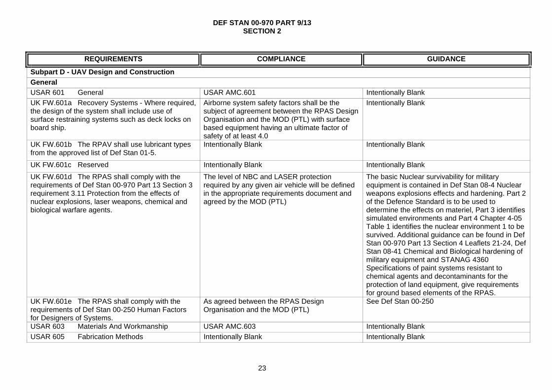
Subpart D - UAV Design and Construction
General
USAR 601 General USAR AMC.601 Intentionally Blank
UK FW.601a Recovery Systems - Where required, the design of the system shall include use of surface restraining systems such as deck locks on board ship.
Airborne system safety factors shall be the subject of agreement between the RPAS Design Organisation and the MOD (PTL) with surface based equipment having an ultimate factor of safety of at least 4.0
Intentionally Blank
UK FW.601b The RPAV shall use lubricant types from the approved list of Def Stan 01-5.
Intentionally Blank Intentionally Blank
UK FW.601c Reserved Intentionally Blank Intentionally Blank
UK FW.601d The RPAS shall comply with the requirements of Def Stan 00-970 Part 13 Section 3 requirement 3.11 Protection from the effects of nuclear explosions, laser weapons, chemical and biological warfare agents.
The level of NBC and LASER protection required by any given air vehicle will be defined in the appropriate requirements document and agreed by the MOD (PTL)
The basic Nuclear survivability for military equipment is contained in Def Stan 08-4 Nuclear weapons explosions effects and hardening. Part 2 of the Defence Standard is to be used to determine the effects on materiel, Part 3 identifies simulated environments and Part 4 Chapter 4-05 Table 1 identifies the nuclear environment 1 to be survived. Additional guidance can be found in Def Stan 00-970 Part 13 Section 4 Leaflets 21-24, Def Stan 08-41 Chemical and Biological hardening of military equipment and STANAG 4360 Specifications of paint systems resistant to chemical agents and decontaminants for the protection of land equipment, give requirements for ground based elements of the RPAS.
UK FW.601e The RPAS shall comply with the requirements of Def Stan 00-250 Human Factors for Designers of Systems.
As agreed between the RPAS Design Organisation and the MOD (PTL)
See Def Stan 00-250
USAR 603 Materials And Workmanship USAR AMC.603 Intentionally Blank
USAR 605 Fabrication Methods Intentionally Blank Intentionally Blank

DEF STAN 00-970 PART 9/13 SECTION 2
24
REQUIREMENTS COMPLIANCE GUIDANCE
UK FW.605a Where a RPAV is to be constructed in modular form, assembly and dismantling shall be simple and require the minimum of jigging and tooling.
The airframe shall utilise substantiated structural technology. New methods shall be substantiated as part of the qualification test programme and approved by the MOD (PTL). The size and mass of the airframe modules shall be compatible with the manpower, handling aids, storage and logistics stated in the RPAS requirement specification.
Intentionally Blank
USAR 607 Fasteners USAR AMC.607 Intentionally Blank
UK FW.607a Fasteners shall be capable of easy operation by personnel wearing the clothing and working in the environmental conditions stated in the RPAS Requirement Specification.
Intentionally Blank Intentionally Blank
UK FW.607b Fasteners shall be proofed against incorrect closure.
Intentionally Blank Intentionally Blank
USAR 609 Protection Of Structure USAR AMC.609 Intentionally Blank
UK FW.609a External colouring and markings of the RPAV shall be in accordance with DAP119A-0601-Series unless otherwise specified in the contract.
The decision to use specific colours shall be agreed by the MOD (PTL). Where a RPAV is of modular construction the nationality and registration mark shall be applied to the fuselage of the vehicle or on the assembly forming the main part of the fuselage.
Where electronics, explosive and close tolerance mechanical devices are fitted inside the fuselage or wings of the RPAV, which could be affected by solar heating absorption, care must be taken to ensure that external coating scheme does not add to the risk of an excessive rise of the internal temperature.
UK FW.609b The colours used for all interior markings and placards shall be in accordance with BS 381C.
Actual colours and markings required shall be agreed prior to contract.
Intentionally Blank
UK FW.609c Air vehicles being regulated under the MAP RA1100 series shall be given a nationality, registration and combatant marking. For other air vehicles a combatant marking only shall be required.
Intentionally Blank To prevent the high usage of registration numbers for target drones, which are eventually destroyed, the recommendation is that a single registration mark (prefix) should be issued by the MAR relating to RPAV type. The Agency or Service operating the equipment will be responsible for the identification of each individual RPAV covered by that registration mark by adding a suffix.

DEF STAN 00-970 PART 9/13 SECTION 2
25
REQUIREMENTS COMPLIANCE GUIDANCE
UK FW.609d RPAVs of modular construction shall have all major assemblies uniquely identified by the manufacturer.
An interchangeable parts register shall be kept for each registered fuselage. The manufacturer shall indelibly mark all components that make up the airframe of the RPAV. Any other assemblies and sub-assemblies that are subjected to fatigue, wear or are interchangeable should also have a record of life.
For the purposes of establishing fatigue life a record should be kept of all exchangeable and replaceable items comprising the RPAV.
USAR 611 Accessibility Provisions USAR AMC.611 Intentionally Blank
UK FW.611a Access hatches shall be large enough to allow adequate access to installed equipment for maintenance and service by personnel wearing the protective clothing (NBC, cold weather, etc.) specified in the RPAS Requirements Specification.
Parts that require regular inspection for replacement shall be readily accessible and care shall be taken to ensure that no sharp edges or corners are exposed where access is required for servicing and/or maintenance.
Intentionally Blank
USAR 613 Material Strength Properties And Design Values
USAR AMC.613 Intentionally Blank
UK FW.613a Any permitted repairs shall ensure that the structural and aerodynamic integrity of the airframe is not degraded and that the airworthiness and safety of the operation of the system is not degraded.
Intentionally Blank The RPAV Design Organisation should define the extent and scope of acceptable repairs, taking account of primary, secondary and tertiary structures in addition the RPAS Requirement Specification should state the service conditions in which repairs are expected to be undertaken.
USAR 619 Special Factors Intentionally Blank Intentionally Blank
USAR 621 Casting Factors Intentionally Blank Intentionally Blank
USAR 623 Bearing Factors Intentionally Blank Intentionally Blank
USAR 625 Fitting Factors Intentionally Blank Intentionally Blank
USAR 627 Fatigue Strength Intentionally Blank Intentionally Blank
USAR 629 Flutter USAR AMC.629 Intentionally Blank
USAR U631 Bird Strike USAR AMC.631 Intentionally Blank
USAR U635 Ground Equipment Affecting Flight Safety
Intentionally Blank Intentionally Blank
Wings

DEF STAN 00-970 PART 9/13 SECTION 2
26
REQUIREMENTS COMPLIANCE GUIDANCE
USAR 641 Proof Of Strength Intentionally Blank Intentionally Blank
Control Surfaces
USAR 651 Proof Of Strength Intentionally Blank Intentionally Blank
USAR 655 Installation Intentionally Blank Intentionally Blank
USAR 657 Hinges Intentionally Blank Intentionally Blank
USAR 659 Mass Balance Intentionally Blank Intentionally Blank
Control Systems
USAR 671 General USAR AMC.671 Intentionally Blank
USAR 673 Primary And Secondary Flight Controls
Intentionally Blank Intentionally Blank
USAR 675 Stops Intentionally Blank Intentionally Blank
USAR 677 Trim Systems Intentionally Blank Intentionally Blank
USAR 679 Primary Or Secondary Flight Controls Lock
Intentionally Blank Intentionally Blank
USAR 681 Limit Load Static Tests Intentionally Blank Intentionally Blank
USAR 683 Operation Tests USAR AMC.683 Intentionally Blank
USAR 685 Control System Details Intentionally Blank Intentionally Blank
USAR 687 Spring Devices Intentionally Blank Intentionally Blank
USAR 689 Cable Systems Intentionally Blank Intentionally Blank
USAR 693 Joints USAR AMC.693 Intentionally Blank
USAR 697 Wing Flap Controls Intentionally Blank Intentionally Blank
USAR 701 Flap Interconnection USAR AMC.701 Intentionally Blank
USAR 703 Take-Off Protection Intentionally Blank Intentionally Blank
Landing Gear
USAR U722 Landing Gear -General Intentionally Blank Intentionally Blank
USAR 723 Shock Absorption Tests Intentionally Blank Intentionally Blank
USAR 725 Limit Drop Tests Intentionally Blank Intentionally Blank
USAR 726 Ground Load Dynamic Tests Intentionally Blank Intentionally Blank
USAR 727 Reserve Energy Absorption Drop Intentionally Blank Intentionally Blank

DEF STAN 00-970 PART 9/13 SECTION 2
27
REQUIREMENTS COMPLIANCE GUIDANCE
Tests
USAR 729 Landing Gear Extension And Retraction System
USAR AMC.729 Intentionally Blank
USAR 731 Wheels Intentionally Blank Intentionally Blank
USAR 733 Tyres Intentionally Blank Intentionally Blank
USAR 735 Brakes USAR AMC.735 Intentionally Blank
USAR 745 Nose/Tail-Wheel Steering Intentionally Blank Intentionally Blank
Payload and Equipment Compartments
USAR 775 Payload Transparencies Intentionally Blank Intentionally Blank
USAR 783 Doors, Covers And Hatches Intentionally Blank Intentionally Blank
USAR 787 Payload Compartments Intentionally Blank Intentionally Blank
Pressurisation
USAR 841 Pressurised Compartments Intentionally Blank Intentionally Blank
USAR 843 Pressurisation Tests Intentionally Blank Intentionally Blank
Fire Protection
USAR U850 Fire Protection - General USAR AMC.850 Intentionally Blank
USAR 863 Flammable Fluid Fire Protection USAR AMC.863 Intentionally Blank
USAR 865 Fire Protection Of Flight Control System Components Engine Mounts And Other Flight Structure
USAR AMC.865 Intentionally Blank
Electrical Bonding and Lightning Protection
USAR 867 Electrical Bonding And Protection Against Lightning And Static Electricity
USAR AMC.867 Intentionally Blank
UK FW.867a Electrical Bonding And Protection Against Lightning And Static Electricity
Intentionally Blank See Def Stan 59-113

DEF STAN 00-970 PART 9/13 SECTION 2
28
REQUIREMENTS COMPLIANCE GUIDANCE
UK FW.867b Mounting and Protection of Components - Components shall be mounted and protected to established standards.
Components shall comply with the requirements of BS EN 60194 Printed Board Design, Manufacture and Assembly, IPC 2221B, Printed Wiring for Electronic Equipment or similar approved design standard agreed with the MOD (PTL). Subject to the operating conditions of components, conformal coating in accordance with the requirements of BS EN-61086-3-1 shall be used to protect circuit boards except where hermetically sealed enclosures are used.
Where identification of individual components is made in printed circuit or mounting boards, the identification where practicable shall be visible. Where practicable, the polarity markings of polarized components shall be placed adjacent to them.
UK FW.867c Static Charge - Equipment that is sensitive to static charge shall be marked accordingly.
Where the design requires Electro Static Sensitive Devices (ESSD) are fitted, precautions shall be taken to minimize the risk of damage to such devices during operation and maintenance. The design of the equipment shall take into account the need to minimize the risk of damage.
Intentionally Blank
UK FW.867d Programmable Memory Devices - The design of modules shall allow for the re-programming of memory devices.
The application of memory devices shall be designed so that, whenever possible, they may be re-programmed on the parent module. Where this is not practicable, the devices shall be easily removable for re-programming.
Intentionally Blank
Parachute Landing System
USAR U881 Parachute Design USAR AMC.881 Intentionally Blank

DEF STAN 00-970 PART 9/13 SECTION 2
29
REQUIREMENTS COMPLIANCE GUIDANCE
Subpart E - UAV Powerplant
General
USAR 901 Installation USAR AMC.901 Intentionally Blank
UK FW.901a For RPAVs utilising turbine / piston engines and rocket motor installations a power plant specification shall be produced based upon the appropriate standards that apply to manned aircraft power plants (in particular Def Stan 00-970 Part 1 Section 5) and associated sub-systems. (See UK 903)
Intentionally Blank Intentionally Blank
UK FW.901b For RPAVs that utilise other methods of propulsion, a power plant specification that provides levels of design integrity and safety consistent with Def Stan 00-970 Part 11 and Part 1 Section 5 shall be produced.
Intentionally Blank Intentionally Blank
UK FW.901c The power plant specification developed to comply with UK 901a or UK 901b shall adequately address any potential hazards or failures modes that could result from operational requirements over and above those for manned aircraft.
Intentionally Blank For example, RPAV power plants may be required to operate under significantly higher G loading than those for manned aircraft.
UK FW.901d The power plant shall be of such a design that it enables the RPAV to comply with operational, reliability, maintainability, environmental and safety requirements defined in the RPAS Requirements Specification.
Intentionally Blank The power plant is defined as the integrated assemblage of components and subsystems that provides the power in the appropriate form for flight propulsion, lift (rotorcraft and VTOL) and auxiliary systems such as electrical power generation. The engine is defined to be the core component that provides motive power and can be of the following configurations gas turbine, reciprocating internal combustion, reciprocating compressed gas, rotary internal combustion ramjet, pulsejet or electric motors. The power plant should have the potential to deliver

DEF STAN 00-970 PART 9/13 SECTION 2
30
REQUIREMENTS COMPLIANCE GUIDANCE
additional power to maintain the specified performance should the RPAV mass increase and where possible, the engine/power module should be a single change unit requiring the minimum number of disconnections. The disturbance to other elements of the propulsion or other systems should also be minimised.
UK FW.901e The use of special tools shall be kept to a minimum.
Any specialist tools to be used shall be agreed by the MOD (PTL)
Intentionally Blank
UK FW.901f The integration of the power plant into the airframe shall be consistent with the acoustic, aerodynamic, radar and thermal signatures of the RPAV.
Intentionally Blank Intentionally Blank
UK FW.901g Systems utilising solid and liquid rocket fuels shall be in accordance with Def Stan 07-85.
Intentionally Blank Intentionally Blank
USAR 903 Engines And Auxiliary Power Units USAR AMC.903 Intentionally Blank
UK FW.903a Engine Starting Systems - For safety reasons, hand-held engine starters shall only be employed when the small size of a RPAV precludes a fixed alternative.
Intentionally Blank The engine starting system may be separate and independent from the RPAV as such consideration should be given to ensure the safety of launch personnel throughout all stages of engine power-up, to the inclusion of guards on the engine starting device and to the provision of a suitable means of stabilisation or support for both the hand-held engine starter and the RPAV.
UK FW.903b All controls for hand-held engine starting devices shall be accessible only to the person starting the engine.
Intentionally Blank Intentionally Blank
UK FW.903c Engine starting devices shall employ safety features such as momentary main switches and over-run clutches.
Intentionally Blank Intentionally Blank

DEF STAN 00-970 PART 9/13 SECTION 2
31
REQUIREMENTS COMPLIANCE GUIDANCE
UK FW.903d For turbine engines, reference shall be made to Def Stan 00-970 Part 1 Sections 5 and 8, Part 11 and CS-E.
Compliance shall be demonstrated against relevant sections within of Def Stan 00-970 Part 1 Sections 5 and 8, and Part 11 and agreed with the MOD (PTL).
Intentionally Blank
UK FW.903e For piston engines, reference shall be made to CS-E and to FAR 33.
Compliance shall be demonstrated against the engine specification requirements within CS-E and agreed with the MOD (PTL)
Intentionally Blank
UK FW.903f For rocket motors, reference shall be made to the requirements set out in Def Stan 07-85.
Compliance shall be demonstrated against the engine specification sections within Def Stan 07-85 and agreed with the MOD (PTL)
Intentionally Blank
UK FW.903g Engine environmental impact shall be minimised.
The design shall be carried out in accordance with ISO 14001 principles.
Intentionally Blank
UK FW.903h The engine shall be mounted in the RPAV in such a manner as to keep transmitted vibration outside frequencies and amplitudes that would have deleterious effects on the integrity and performance of the RPAV structures, mechanisms, avionics and payload or harmful effects to personnel (for example during hand held launch) or the general public.
The RPAV Design Organisation and the RPAV Power plant Design Organisation shall agree vibration limits caused by the interaction of the power plant and the RPAV in all configurations such that the performance or safety requirements of the RPAV stated in the RPAS Requirement Specification are not unacceptably compromised.
Intentionally Blank
UK FW.903j The use of novel engine design or configurations shall be approved by the MOD (PTL)
Novel engine designs shall meet the requirements of Def Stan 00-970 Part 11 and Part 1 Section 5.
It should be noted that novel engine configurations will be subjected to the certification processes as defined in Def Stan 00-970 part 11 and Map RA 5000 series.
UK FW.903k Sufficient power shall be available to cover the maximum load conditions of the RPAS.
A power requirement calculation shall be performed.
Consideration should be given to the inclusion of a tolerance for potential future development. The power requirement calculation should take into account electrical, mechanical, pneumatic or hydraulic subsystems and possible payloads.
UK FW.903l Power Loading - Operational degradation due to partial loss of power shall be managed.
Critical systems shall be identified and priority given to maintaining their integrity.
The critical systems may be considered to be the RPAV flight control and safety systems and Consideration should be given to selective load shedding for operational contingencies.

DEF STAN 00-970 PART 9/13 SECTION 2
32
REQUIREMENTS COMPLIANCE GUIDANCE
USAR 905 Propellers USAR AMC.905 Intentionally Blank
UK FW.905a The design of the propeller shall be consistent with the acoustic, thermal, radar and visual signatures as specified in the RPAS Requirement Specification.
Intentionally Blank Intentionally Blank
UK FW.905b Positive indication that propeller blades are correctly and securely fitted shall be provided.
Intentionally Blank Intentionally Blank
USAR 907 Propeller Vibration USAR AMC.907 Intentionally Blank
USAR 909 Turbo Charger Systems USAR AMC.909 Intentionally Blank
USAR 925 Propeller Clearance Intentionally Blank Intentionally Blank
USAR 929 Engine Installation Ice Protection Intentionally Blank Intentionally Blank
USAR 933 Thrust Reversing Systems Intentionally Blank Intentionally Blank
USAR 934 Turbojet And Turbo Fan Engine Thrust Reverser System Tests
USAR AMC.934 Intentionally Blank
USAR 937 Turbopropeller-Drag Limiting Systems
Intentionally Blank Intentionally Blank
USAR 939 Powerplant Operation Characteristics
USAR AMC.939 Intentionally Blank
USAR 943 Negative Acceleration Intentionally Blank Intentionally Blank
Fuel System
USAR 951 General Intentionally Blank Intentionally Blank
USAR 953 Fuel System Independence Intentionally Blank Intentionally Blank
USAR 954 Fuel System Lightning Protection Intentionally Blank Intentionally Blank
UK FW.954a Fuel System Lightning Protection Intentionally Blank See Def Stan 59-113
USAR 955 Fuel Flow Intentionally Blank Intentionally Blank
USAR 957 Flow Between Interconnected Tanks Intentionally Blank Intentionally Blank
USAR 959 Unusable Fuel Supply USAR AMC.959 Intentionally Blank
USAR 961 Fuel System Hot Weather Operation USAR AMC.961 Intentionally Blank
USAR 963 Fuel Tanks General Intentionally Blank Intentionally Blank
USAR 965 Fuel Tank Tests Intentionally Blank Intentionally Blank

DEF STAN 00-970 PART 9/13 SECTION 2
33
REQUIREMENTS COMPLIANCE GUIDANCE
USAR 967 Fuel Tank Installation USAR AMC.967 Intentionally Blank
USAR 969 Fuel Tank Expansion Space Intentionally Blank Intentionally Blank
USAR 971 Fuel Tank Sump Intentionally Blank Intentionally Blank
USAR 973 Fuel Tank Filler Connection USAR AMC.973 Intentionally Blank
USAR 975 Fuel Tank Vents And Carburettor Vapour Vents
USAR AMC.975 Intentionally Blank
USAR 977 Fuel Tank Outlet Intentionally Blank Intentionally Blank
USAR 979 Pressure Fuelling Systems Intentionally Blank Intentionally Blank
Fuel System Components
USAR 991 Fuel Pumps Intentionally Blank Intentionally Blank
USAR 993 Fuel System Lines And Fittings USAR AMC.993 Intentionally Blank
USAR 994 Fuel System Components Intentionally Blank Intentionally Blank
USAR 995 Fuel Valves And Controls USAR AMC.995 Intentionally Blank
USAR 997 Fuel Strainer Or Filter USAR AMC.997 Intentionally Blank
USAR 999 Fuel System Drains USAR AMC.999 Intentionally Blank
USAR 1001 Fuel Jettisoning System USAR AMC.1001 Intentionally Blank
Oil System
USAR 1011 General USAR AMC.1011 Intentionally Blank
USAR 1013 Oil Tanks Intentionally Blank Intentionally Blank
USAR 1015 Oil Tank Tests Intentionally Blank Intentionally Blank
USAR 1017 Oil Lines And Fittings Intentionally Blank Intentionally Blank
USAR 1019 Oil Strainer Or Filter Intentionally Blank Intentionally Blank
USAR 1021 Oil System Drains Intentionally Blank Intentionally Blank
USAR 1023 Oil Radiators Intentionally Blank Intentionally Blank
USAR 1027 Propeller Feathering System Intentionally Blank Intentionally Blank
Cooling
USAR 1041 General Intentionally Blank Intentionally Blank

DEF STAN 00-970 PART 9/13 SECTION 2
34
REQUIREMENTS COMPLIANCE GUIDANCE
UK FW.1041a The location of any cooling air apertures, ducts or radiators shall be consistent with the requirements for acoustic, radar, thermal and visual signatures.
Intentionally Blank Intentionally Blank
USAR 1043 Cooling Tests Intentionally Blank Intentionally Blank
USAR 1045 Cooling Test Procedures For Turbine Engine-Powered UAV
USAR AMC.1045 Intentionally Blank
USAR 1047 Cooling Test Procedures For Reciprocating Engine-Powered UAV
USAR AMC.1047 Intentionally Blank
Liquid Cooling
USAR 1061 Installation Intentionally Blank Intentionally Blank
USAR 1063 Coolant Tank Tests Intentionally Blank Intentionally Blank
Induction System
USAR 1091 Air Induction System USAR AMC.1091 Intentionally Blank
UK FW.1091a The installation of the induction system shall ensure that adequate protection is provided for personnel.
Hazard and warning signs shall be displayed on the appropriate surfaces and locations of the RPAV.
Consideration should be given to the use of ground running guards.
UK FW.1091b The induction system shall be consistent with the requirements for RPAV acoustic, radar, thermal and visual signatures.
Intentionally Blank Intentionally Blank
USAR 1093 Induction System Icing Protection USAR AMC.1093 Intentionally Blank
USAR 1095 Carburettor De-Icing Fluid Flow Rate USAR AMC.1095 Intentionally Blank
USAR 1097 Carburettor De-Icing Fluid System Capacity
Intentionally Blank Intentionally Blank
USAR 1099 Carburettor De-Icing Fluid System Detail Design
Intentionally Blank Intentionally Blank
USAR 1101 Induction Air Preheated Design Intentionally Blank Intentionally Blank
USAR 1103 Induction System Ducts USAR AMC.1103 Intentionally Blank
USAR 1105 Induction System Screens Intentionally Blank Intentionally Blank
USAR 1107 Induction System Filters Intentionally Blank Intentionally Blank
DEF STAN 00-970 PART 9/13 SECTION 2
35
REQUIREMENTS COMPLIANCE GUIDANCE
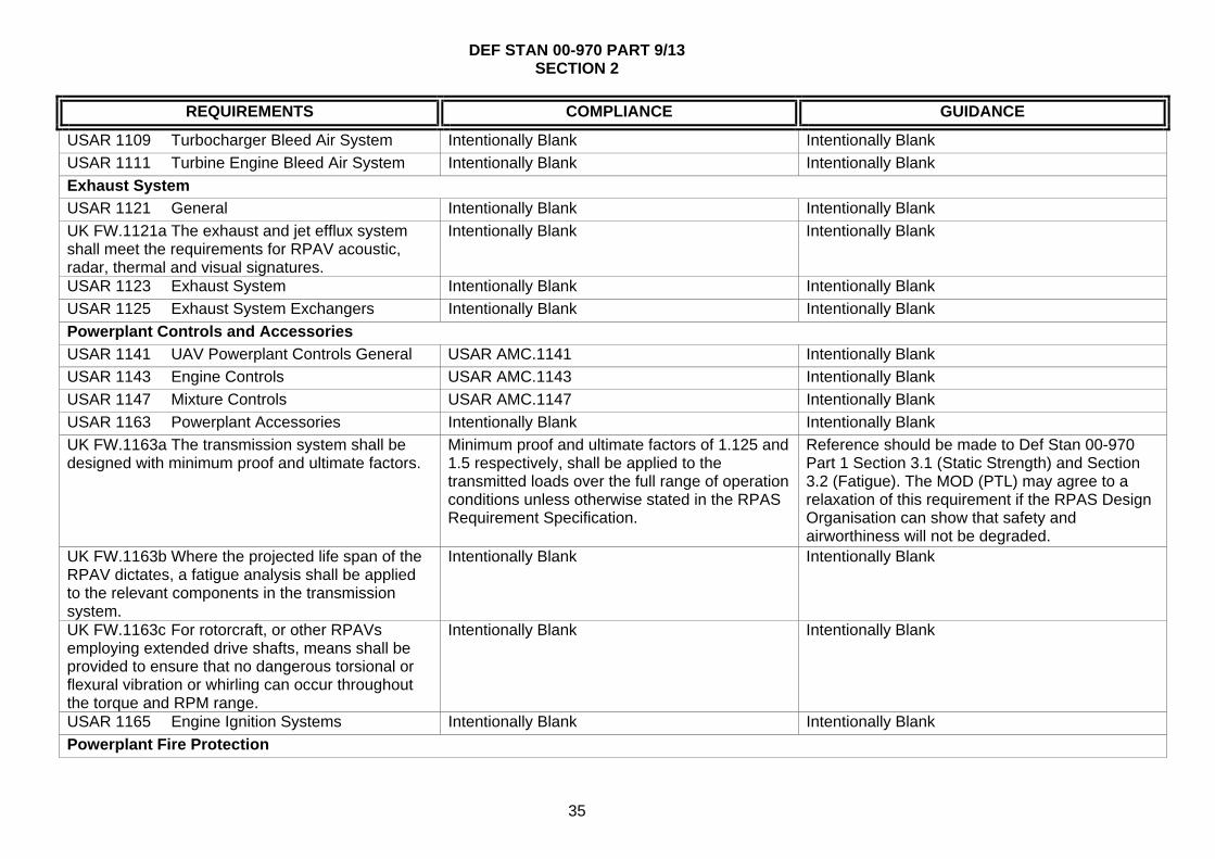
USAR 1109 Turbocharger Bleed Air System Intentionally Blank Intentionally Blank
USAR 1111 Turbine Engine Bleed Air System Intentionally Blank Intentionally Blank
Exhaust System
USAR 1121 General Intentionally Blank Intentionally Blank
UK FW.1121a The exhaust and jet efflux system shall meet the requirements for RPAV acoustic, radar, thermal and visual signatures.
Intentionally Blank Intentionally Blank
USAR 1123 Exhaust System Intentionally Blank Intentionally Blank
USAR 1125 Exhaust System Exchangers Intentionally Blank Intentionally Blank
Powerplant Controls and Accessories
USAR 1141 UAV Powerplant Controls General USAR AMC.1141 Intentionally Blank
USAR 1143 Engine Controls USAR AMC.1143 Intentionally Blank
USAR 1147 Mixture Controls USAR AMC.1147 Intentionally Blank
USAR 1163 Powerplant Accessories Intentionally Blank Intentionally Blank
UK FW.1163a The transmission system shall be designed with minimum proof and ultimate factors.
Minimum proof and ultimate factors of 1.125 and 1.5 respectively, shall be applied to the transmitted loads over the full range of operation conditions unless otherwise stated in the RPAS Requirement Specification.
Reference should be made to Def Stan 00-970 Part 1 Section 3.1 (Static Strength) and Section 3.2 (Fatigue). The MOD (PTL) may agree to a relaxation of this requirement if the RPAS Design Organisation can show that safety and airworthiness will not be degraded.
UK FW.1163b Where the projected life span of the RPAV dictates, a fatigue analysis shall be applied to the relevant components in the transmission system.
Intentionally Blank Intentionally Blank
UK FW.1163c For rotorcraft, or other RPAVs employing extended drive shafts, means shall be provided to ensure that no dangerous torsional or flexural vibration or whirling can occur throughout the torque and RPM range.
Intentionally Blank Intentionally Blank
USAR 1165 Engine Ignition Systems Intentionally Blank Intentionally Blank
Powerplant Fire Protection

DEF STAN 00-970 PART 9/13 SECTION 2
36
REQUIREMENTS COMPLIANCE GUIDANCE
USAR 1181 Designated Fire Zones Regions Included
Intentionally Blank Intentionally Blank
USAR 1183 Lines, Fittings And Components Intentionally Blank Intentionally Blank
USAR 1189 Shut-Off Means USAR AMC.1189 Intentionally Blank
USAR 1191 Firewalls USAR AMC.1191 Intentionally Blank
USAR 1192 Engine Accessory Compartment Diaphragm
Intentionally Blank Intentionally Blank
USAR 1193 Cowling And Nacelle USAR AMC.1193 Intentionally Blank
USAR 1195 Fire Extinguishing Systems Intentionally Blank Intentionally Blank
USAR 1203 Fire Detector System Intentionally Blank Intentionally Blank
DEF STAN 00-970 PART 9/13 SECTION 2
37
REQUIREMENTS COMPLIANCE GUIDANCE
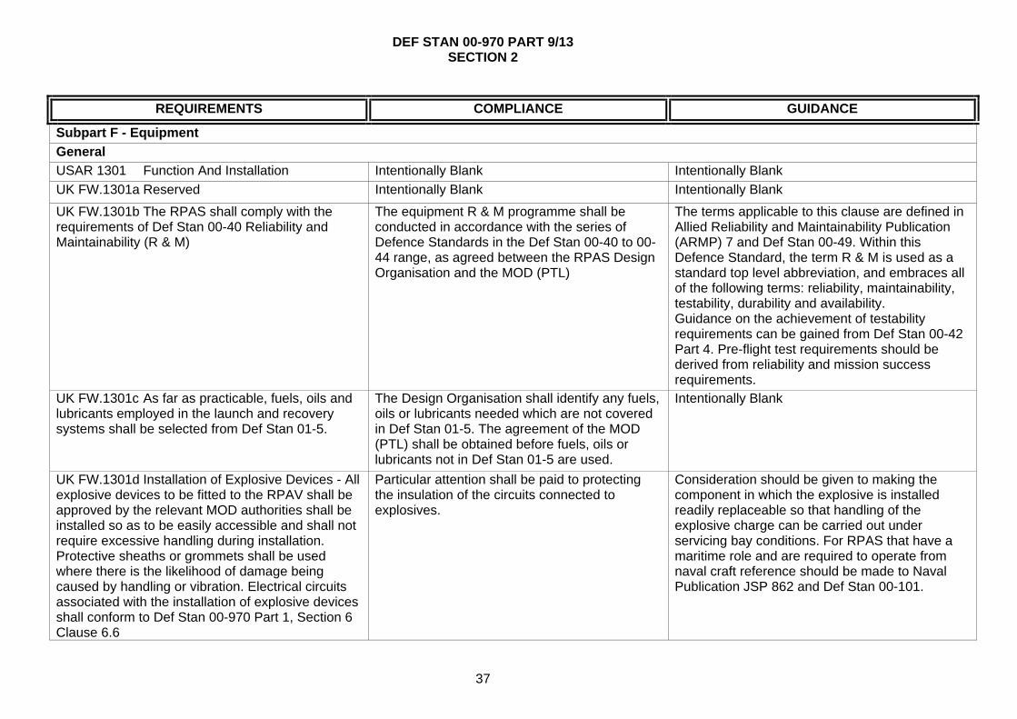
Subpart F - Equipment
General
USAR 1301 Function And Installation Intentionally Blank Intentionally Blank
UK FW.1301a Reserved Intentionally Blank Intentionally Blank
UK FW.1301b The RPAS shall comply with the requirements of Def Stan 00-40 Reliability and Maintainability (R & M)
The equipment R & M programme shall be conducted in accordance with the series of Defence Standards in the Def Stan 00-40 to 00-44 range, as agreed between the RPAS Design Organisation and the MOD (PTL)
The terms applicable to this clause are defined in Allied Reliability and Maintainability Publication (ARMP) 7 and Def Stan 00-49. Within this Defence Standard, the term R & M is used as a standard top level abbreviation, and embraces all of the following terms: reliability, maintainability, testability, durability and availability. Guidance on the achievement of testability requirements can be gained from Def Stan 00-42 Part 4. Pre-flight test requirements should be derived from reliability and mission success requirements.
UK FW.1301c As far as practicable, fuels, oils and lubricants employed in the launch and recovery systems shall be selected from Def Stan 01-5.
The Design Organisation shall identify any fuels, oils or lubricants needed which are not covered in Def Stan 01-5. The agreement of the MOD (PTL) shall be obtained before fuels, oils or lubricants not in Def Stan 01-5 are used.
Intentionally Blank
UK FW.1301d Installation of Explosive Devices - All explosive devices to be fitted to the RPAV shall be approved by the relevant MOD authorities shall be installed so as to be easily accessible and shall not require excessive handling during installation. Protective sheaths or grommets shall be used where there is the likelihood of damage being caused by handling or vibration. Electrical circuits associated with the installation of explosive devices shall conform to Def Stan 00-970 Part 1, Section 6 Clause 6.6
Particular attention shall be paid to protecting the insulation of the circuits connected to explosives.
Consideration should be given to making the component in which the explosive is installed readily replaceable so that handling of the explosive charge can be carried out under servicing bay conditions. For RPAS that have a maritime role and are required to operate from naval craft reference should be made to Naval Publication JSP 862 and Def Stan 00-101.

DEF STAN 00-970 PART 9/13 SECTION 2
38
REQUIREMENTS COMPLIANCE GUIDANCE
USAR U1304 Navigation Architecture Intentionally Blank Intentionally Blank
USAR U1307 Environmental Control System (ECS)
USAR AMC.1307 Intentionally Blank
USAR 1309 Equipment, Systems And Installations
USAR AMC.1309 Intentionally Blank
UK FW.1309a Refer to "UK National Reservations" in part 1 - 1.2.2.c.(3)
Intentionally Blank Intentionally Blank
UK FW.1309b. Safety Management Safety Management for all aspects of the RPAS to be in accordance with Def Stan 00-56, or an agreed equivalent standard.
Intentionally Blank
Measuring Devices Installation
USAR 1323 Airspeed Measuring Device Intentionally Blank Intentionally Blank
USAR 1325 Static Pressure Measuring Device USAR AMC.1325 Intentionally Blank
USAR 1327 Magnetic Heading Measuring Device Intentionally Blank Intentionally Blank
UK FW.1327a Installation of Magnetic Compass - The design shall take into account the need for implementing and carrying out De-magnetisation, Compass Safe Distance and Compass Swing Accuracy.
Information contained in Def Stan 00-970 Part. 1 Section 6.4 and BS G 262 shall be used to satisfy these requirements.
Intentionally Blank
USAR U1330 Flight Control Performance USAR AMC.1330 Intentionally Blank
UK FW.1330a Reversionary navigation capability shall be provided to ensure safety of flight.
The needs for, and performance requirements of, separate navigation systems shall be established in the RPAS Safety Case and specified in the RPAS Requirements Specification. Alternative navigation sensors listed under Guidance shall be considered.
The following should be considered as reversionary navigation sensors: Dead reckoning from fluxgate and air data, communication/data links range and bearing, Terrain referenced navigation and scene matching navigation. The choice may depend on terminal navigation requirements derived from mission success criteria.
USAR 1331 Measuring Device Using A Power Source
Intentionally Blank Intentionally Blank
USAR 1337 Powerplant Installation Measuring Device
Intentionally Blank Intentionally Blank

DEF STAN 00-970 PART 9/13 SECTION 2
39
REQUIREMENTS COMPLIANCE GUIDANCE
Electrical Systems and Equipment
USAR 1351 General USAR AMC.1351 Intentionally Blank
UK FW.1351a Electrical Systems and Wiring - The requirements of Def Stan 00-970 Part 1 Section 6 Leaflets 4, 14, 15, 16, and 35 shall be considered.
These requirements shall supplement the CS 1351 and 1353 requirements except where agreed with the MOD (PTL)
Intentionally Blank
UK FW.1351b Electrical Systems and Wiring - The installation shall be designed for ease of maintenance.
Intentionally Blank Intentionally Blank
UK FW.1351c If the air vehicle carries a payload that is designed to be jettisoned or released on command, the electrical installation of the arming and release system shall conform to Def Stan 00-970 Part 13 Sections 3.1 (Armament Installations – General), 3.2 (Armament Control System) and 3.14 (Integration of Stores)
Intentionally Blank Intentionally Blank
UK FW.1351d Electrical Interfaces - Established standards such as RS 422, MIL STD 1760 and MIL STD 1553B shall be used wherever practicable.
Intentionally Blank Intentionally Blank
USAR 1353 Storage Battery Or Emergency Power Supply Design And Installation
Intentionally Blank Intentionally Blank
UK FW.1353a Other fuels and Energy Sources - Where unconventional energy sources are utilised, they shall not hazard personnel or adversely affect the air vehicle.
Where unconventional energy sources are proposed they shall be agreed by the MOD (PTL).
Unconventional energy sources currently include the use of solar energy, microwave energy and regeneration systems. It should be noted that such systems might, in due course, be considered conventional.

DEF STAN 00-970 PART 9/13 SECTION 2
40
REQUIREMENTS COMPLIANCE GUIDANCE
UK FW.1353b The RPAS shall comply with the requirements of Def Stan 59-411- Electromagnetic Compatibility, for EMC and ECM, and Def Stan 59-113 for Lightening protection.
The control plan, requirements, trials and Tests shall be agreed by the MOD (PTL)
The achievement of EMC in a RPAS is a relatively complex matter because of the different nature of the requirement for the Air Vehicle, Ground Control Elements and the Communication/Data Links between the two and to the “outside world” in respect of a relatively “small” RPAS. The differing requirements for Sea, Air and Land systems should be taken into account. DE3A (Contact details in Def Stan 59-411) should be consulted, being able to offer E3 Functional Assurance at all stages of a project.
USAR 1357 Circuit Protection Devices USAR AMC.1357 Intentionally Blank
USAR 1359 Electrical System Fire Protection Intentionally Blank Intentionally Blank
USAR 1361 Master Switch Arrangement USAR AMC.1361 Intentionally Blank
USAR 1365 Electric Cables And Equipment Intentionally Blank Intentionally Blank
UK FW.1365a Cable runs and connector orientation shall be such as to enable easy and correct connection and disconnection of units in the field.
Intentionally Blank RPAVs may be smaller than their manned equivalents and the environment for servicing may be more severe. Good design of cable runs can obviate damage during servicing.
USAR 1367 Switches Intentionally Blank Intentionally Blank
Lights
USAR 1383 Taxi And Landing Lights Intentionally Blank Intentionally Blank
USAR 1385 Position Light System Installation Intentionally Blank Intentionally Blank
USAR 1387 Position Light System Dihedral Angles
Intentionally Blank Intentionally Blank
USAR 1389 Position Light Distribution And Intensities
Intentionally Blank Intentionally Blank
USAR 1391 Minimum Intensities In The Horizontal Plane Of Position Lights
Intentionally Blank Intentionally Blank
USAR 1393 Minimum Intensities In Any Vertical Plane Of Position Lights
Intentionally Blank Intentionally Blank
USAR 1395 Maximum Intensities In Overlapping Beams Of Position Lights
Intentionally Blank Intentionally Blank

DEF STAN 00-970 PART 9/13 SECTION 2
41
REQUIREMENTS COMPLIANCE GUIDANCE
USAR 1397 Colour Specifications Intentionally Blank Intentionally Blank
USAR 1401 Anti-Collision Light System Intentionally Blank Intentionally Blank
Safety equipment and Emergency Capability
USAR U1412 Emergency Recovery Capability USAR AMC.1412 Intentionally Blank
UK FW.U1412a Flight Termination - Safety and Reliability - The RPAS Requirements Specification shall identify any operational scenarios where the normal function of the FTS is to be inhibited.
Intentionally Blank Conditions in which it may be necessary to inhibit the operation of the FTS may include the period immediately after launch when it is necessary to achieve a safe separation distance from the launch platform, any period during recovery or retrieval when operation of the FTS could increase the risk to personnel or third parties being overflown or within the vicinity or if launch has been inhibited after propulsion system ignition.
UK FW.U1412b Flight Termination - The RPAS Requirement Specification shall state the extent to which the FTS shall be resistant to internal and external interference including jamming.
See Clause UK 1353b Intentionally Blank
USAR U1413 Engine Shut Down Procedure Intentionally Blank Intentionally Blank
USAR 1416 De-Icer System Intentionally Blank Intentionally Blank
USAR 1419 Ice Protection Intentionally Blank Intentionally Blank
Miscellaneous Equipment
USAR 1431 Electronic Equipment USAR AMC 1431 Intentionally Blank
UK FW.1431a Radio and Radar Installations - Radio and radar installations shall be such that when utilising the RPAV power source they shall achieve optimum specified performance, even when subjected to their most severe environmental conditions.
The location of the aerial(s) on the RPAV shall take into account: signal polarisation, required radiation pattern, electromagnetic interference, multipath signal reflections, optimised radiation efficiency, matched aerials (if homing is a requirement), and the ability to withstand mechanical loading and damage.
The Radio and Radar installations comprise those items of equipment including LRUs that form the communication and guidance system of the RPAV and includes the aerial design. It is recommended that the following Defence Standards shall be referred to where necessary: Def Stan 00-18 - Avionic Data Transmission, Def Stan 00-56 – Safety Management Requirements for Defence Systems and IEC TS 62239-1 Process management for avionics. Management
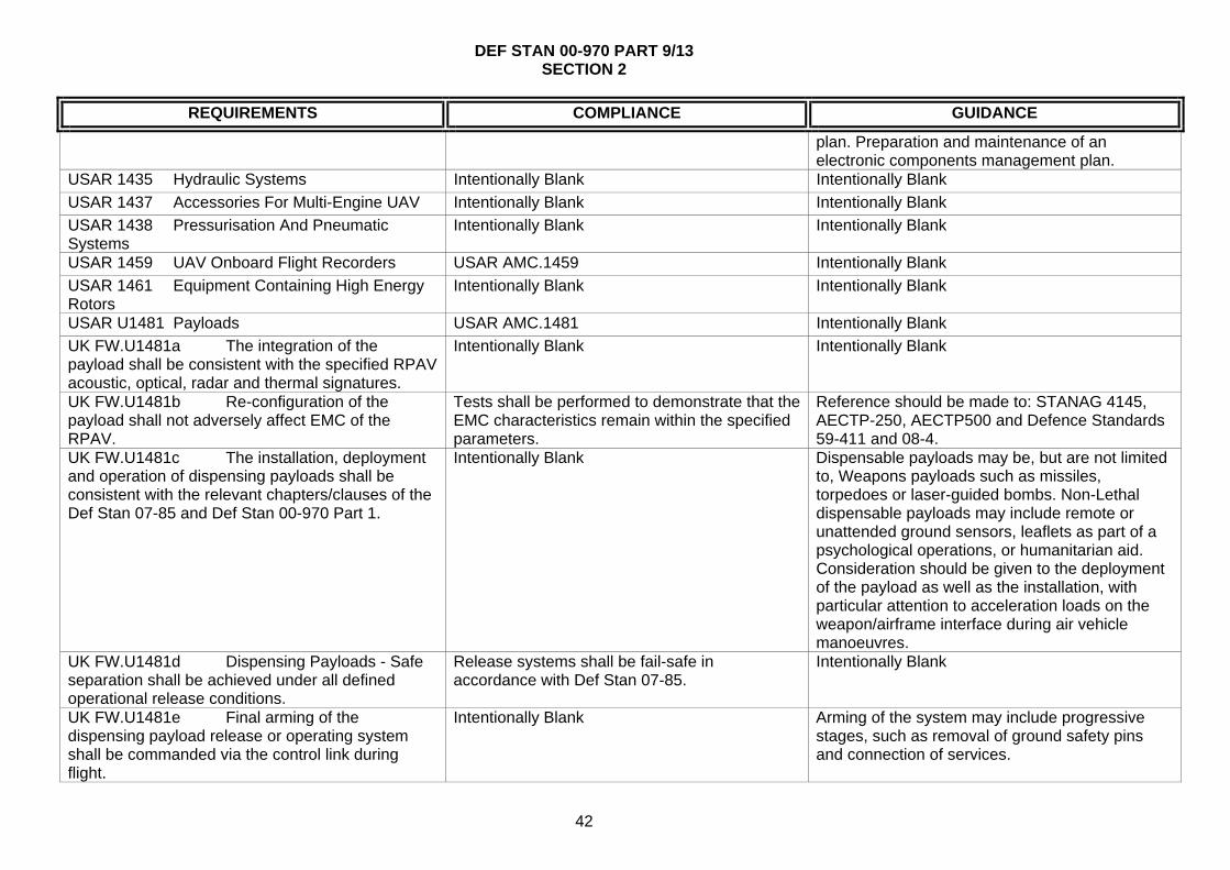
DEF STAN 00-970 PART 9/13 SECTION 2
42
REQUIREMENTS COMPLIANCE GUIDANCE
plan. Preparation and maintenance of an electronic components management plan.
USAR 1435 Hydraulic Systems Intentionally Blank Intentionally Blank
USAR 1437 Accessories For Multi-Engine UAV Intentionally Blank Intentionally Blank
USAR 1438 Pressurisation And Pneumatic Systems
Intentionally Blank Intentionally Blank
USAR 1459 UAV Onboard Flight Recorders USAR AMC.1459 Intentionally Blank
USAR 1461 Equipment Containing High Energy Rotors
Intentionally Blank Intentionally Blank
USAR U1481 Payloads USAR AMC.1481 Intentionally Blank
UK FW.U1481a The integration of the payload shall be consistent with the specified RPAV acoustic, optical, radar and thermal signatures.
Intentionally Blank Intentionally Blank
UK FW.U1481b Re-configuration of the payload shall not adversely affect EMC of the RPAV.
Tests shall be performed to demonstrate that the EMC characteristics remain within the specified parameters.
Reference should be made to: STANAG 4145, AECTP-250, AECTP500 and Defence Standards 59-411 and 08-4.
UK FW.U1481c The installation, deployment and operation of dispensing payloads shall be consistent with the relevant chapters/clauses of the Def Stan 07-85 and Def Stan 00-970 Part 1.
Intentionally Blank Dispensable payloads may be, but are not limited to, Weapons payloads such as missiles, torpedoes or laser-guided bombs. Non-Lethal dispensable payloads may include remote or unattended ground sensors, leaflets as part of a psychological operations, or humanitarian aid. Consideration should be given to the deployment of the payload as well as the installation, with particular attention to acceleration loads on the weapon/airframe interface during air vehicle manoeuvres.
UK FW.U1481d Dispensing Payloads - Safe separation shall be achieved under all defined operational release conditions.
Release systems shall be fail-safe in accordance with Def Stan 07-85.
Intentionally Blank
UK FW.U1481e Final arming of the dispensing payload release or operating system shall be commanded via the control link during flight.
Intentionally Blank Arming of the system may include progressive stages, such as removal of ground safety pins and connection of services.

DEF STAN 00-970 PART 9/13 SECTION 2
43
REQUIREMENTS COMPLIANCE GUIDANCE
UK FW.U1481f Dispensing Payloads - In the event of the payload misfiring or failing to operate, the RPAV must be capable of safe recovery, cut down, or disposal of the payload.
The system shall ensure the RPAV-pilot(s)/Commander have verification of payload operation (successful or not) at each phase.
The method employed for safe recovery, cut down, or disposal of the payload is dependent upon the nature of the payload and operating scenario.
USAR U1485 Environmental Control System (ECS)
USAR AMC.1485 Intentionally Blank
Automatic Take-Off, Taxi, Landing
USAR U1490 Automatic take-off system, automatic landing system
USAR AMC.1490 Intentionally Blank
USAR U1492 Manual Abort Function Intentionally Blank Intentionally Blank
USAR U1494 Automatic Taxi System Intentionally Blank Intentionally Blank

DEF STAN 00-970 PART 9/13 SECTION 2
44
REQUIREMENTS COMPLIANCE GUIDANCE
Subpart G - Operating Limitations and Information
General
USAR 1501 General Intentionally Blank Intentionally Blank
USAR 1505 Airspeed Limitations Intentionally Blank Intentionally Blank
USAR 1507 Manoeuvring Speed Intentionally Blank Intentionally Blank
USAR 1511 Flap Extended Speed Intentionally Blank Intentionally Blank
USAR 1513 Minimum Control Speed Intentionally Blank Intentionally Blank
USAR 1519 Weight And Centre Or Gravity Intentionally Blank Intentionally Blank
USAR 1521 Powerplant Limitations Intentionally Blank Intentionally Blank
USAR 1522 Auxiliary Power Unit Limitations Intentionally Blank Intentionally Blank
USAR 1525 Kinds Of Operation Intentionally Blank Intentionally Blank
USAR 1527 Maximum Operating Altitude Intentionally Blank Intentionally Blank
USAR 1529 Instructions For Continued Airworthiness
Intentionally Blank Intentionally Blank
Information, Markings and Placards
USAR 1541 General Intentionally Blank Intentionally Blank
USAR 1543 Instrument Markings- General Intentionally Blank Intentionally Blank
USAR 1551 Oil Quantity Indicator Intentionally Blank Intentionally Blank
USAR 1553 Fuel Quantity Indicator Intentionally Blank Intentionally Blank
USAR 1555 Control Markings On The UAV Intentionally Blank Intentionally Blank
UK FW.1555a Emergency controls (see Def Stan 00-970 Part 1, Section 4, clauses 22 to 24) to be coloured iaw Def Stan 00-970 Part 1 Section 7 requirement 7.4 - Operational Colouring and Markings.
Intentionally Blank Intentionally Blank
USAR 1557 Miscellaneous Information Markings And Placards
Intentionally Blank Intentionally Blank
UAV System Flight Manual
USAR 1581 General Intentionally Blank Intentionally Blank

DEF STAN 00-970 PART 9/13 SECTION 2
45
REQUIREMENTS COMPLIANCE GUIDANCE
USAR 1583 Operating Limitations Intentionally Blank Intentionally Blank
USAR 1585 Operating Procedures Intentionally Blank Intentionally Blank
USAR 1587 Performance Information USAR AMC.1587 Intentionally Blank
USAR 1589 Loading Information Intentionally Blank Intentionally Blank
USAR U1591 Data Link Information Intentionally Blank Intentionally Blank
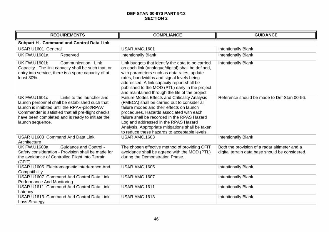
DEF STAN 00-970 PART 9/13 SECTION 2
46
REQUIREMENTS COMPLIANCE GUIDANCE
Subpart H - Command and Control Data Link
USAR U1601 General USAR AMC.1601 Intentionally Blank
UK FW.U1601a Reserved Intentionally Blank Intentionally Blank
UK FW.U1601b Communication - Link Capacity - The link capacity shall be such that, on entry into service, there is a spare capacity of at least 30%.
Link budgets that identify the data to be carried on each link (analogue/digital) shall be defined, with parameters such as data rates, update rates, bandwidths and signal levels being addressed. A link capacity report shall be published to the MOD (PTL) early in the project and maintained through the life of the project.
Intentionally Blank
UK FW.U1601c Links to the launcher and launch personnel shall be established such that launch is inhibited until the RPAV-pilot/RPAV Commander is satisfied that all pre-flight checks have been completed and is ready to initiate the launch sequence.
Failure Modes Effects and Criticality Analysis (FMECA) shall be carried out to consider all failure modes and their effects on launch procedures. Hazards associated with each failure shall be recorded in the RPAS Hazard Log and addressed in the RPAS Hazard Analysis. Appropriate mitigations shall be taken to reduce these hazards to acceptable levels.
Reference should be made to Def Stan 00-56.
USAR U1603 Command And Data Link Architecture
USAR AMC.1603 Intentionally Blank
UK FW.U1603a Guidance and Control - Safety consideration - Provision shall be made for the avoidance of Controlled Flight Into Terrain (CFIT)
The chosen effective method of providing CFIT avoidance shall be agreed with the MOD (PTL) during the Demonstration Phase.
Both the provision of a radar altimeter and a digital terrain data base should be considered.
USAR U1605 Electromagnetic Interference And Compatibility
USAR AMC.1605 Intentionally Blank
USAR U1607 Command And Control Data Link Performance And Monitoring
USAR AMC.1607 Intentionally Blank
USAR U1611 Command And Control Data Link Latency
USAR AMC.1611 Intentionally Blank
USAR U1613 Command And Control Data Link Loss Strategy
USAR AMC.1613 Intentionally Blank

DEF STAN 00-970 PART 9/13 SECTION 2
47
REQUIREMENTS COMPLIANCE GUIDANCE
USAR U1615 Command And Control Data Link Antenna Maskings
USAR AMC.1615 Intentionally Blank
UK FW.U1615a Covert Operation - The antenna installation shall meet requirements for covert operation.
Intentionally Blank Intentionally Blank
USAR U1617 Command And Control Data Link Switchover Function
USAR AMC.1617 Intentionally Blank

DEF STAN 00-970 PART 9/13 SECTION 2
48
REQUIREMENTS COMPLIANCE GUIDANCE
Subpart I - UAV Control Station
General
USAR U1701 General USAR AMC.1701 Intentionally Blank
UK FW.U1701a Portable equipment for use in the field shall comply with the requirements of Def Stan 00-35 Environmental Handbook for Defence Materiel.
Portable equipment shall be designed to withstand the environment that it will experience when stowed in its parent facility, and the additional conditions to which it may be subjected when in use outside the facility - See AECTP 100-500 series Environmental Guidelines For Defence Materiel.
Intentionally Blank
UK FW.U1701b The design of the RPAS Support Facilities shall be consistent with the transportation requirements stated in the RPAS Requirements Specification.
Unless otherwise stated in the RPAS Requirements Specification, the requirements of Def Stan 00-3 shall apply.
Intentionally Blank
UK FW.U1701c The safety of the RPAS Support Facilities shall be consistent with achieving the overall safety of the complete RPAS.
The RPAS Support Facilities shall be designed in accordance with Health and Safety legislation and the safety management procedures of Def Stan 00-56. The RPAS Design Organisation shall produce a Safety Programme Plan. As part of the RPAS Safety Case, hazards associated with the RPAS Support Facilities will be identified in the RPAS Hazard log and addressed in the RPAS Hazard Analysis.
Intentionally Blank

DEF STAN 00-970 PART 9/13 SECTION 2
49
REQUIREMENTS COMPLIANCE GUIDANCE
UK FW.U1701d RPAS Support Facilities shall be fire proof wherever possible and comply with the applicable fire regulations.
Where complete fireproofing is not practicable the materials used in the design shall be selected to provide the greatest degree of fire resistance possible and to minimise the emission of toxic fumes.
BSI BS 476(Fire tests on building materials and structures), BS 5266 (Emergency Lighting), BS5499 (Fire Signs), BS5852 (Assessment of upholstered seating) AFNOR NF EN3 (Portable fire extinguishers), Fire Prevention on Construction Sites (published by the British Employers Confederation, the Loss Prevention Council and the National Contractors Group) and CS-Definitions, contain information which may be of assistance when determining the construction and location of RPAS Support Facilities elements. Note should be taken of any special requirements for airborne or shipborne installations.
UK FW.U1701e All emissions from the RPAS Support Facilities (such as RF, Infra Red, Visible, Ultra Violet, Audio, Laser) shall be controlled to meet the system detectability requirements.
Where possible, sources of radiated energy shall be sited remotely from the main control station. The compatibility of the Support facility with emission requirements shall be determined by analysis or demonstrated by test and trial to ensure that there is no interference with other aspects of the system's operation, it does not interfere with other systems or equipment in the vicinity, it does not present itself as a large target to attacking forces nor shall it cause harm or injury to operating personnel.
Intentionally Blank
UK FW.U1701f RPAS Support Facilities shall comply with the requirements of NBC compatibility called for in the RPAS Requirements Specification.
Unless otherwise detailed in the RPAS Requirements Specification, the RPAS Design Organisation shall make reference to Def Stan 08-4 (for nuclear environments), and Def Stan 08-41 Parts 1 and 2 for chemical environments. The MOD (PTL) shall stipulate whether all or which parts of the above documents are mandatory.
If further information is required, the MOD (PTL) should be approached for guidance on the conditions to be considered in the RPAS Requirements Specification.
USAR U1702 UCS Infrastructure Intentionally Blank Intentionally Blank

DEF STAN 00-970 PART 9/13 SECTION 2
50
REQUIREMENTS COMPLIANCE GUIDANCE
UK FW.U1702a The stowage of hazardous systems such as fuel, rocket motors, pyrotechnics and other inflammable and explosive substances shall be in accordance with JSP 482.
Intentionally Blank JSP 482 also gives associated publications that could be relevant and should be referenced in the RPAS Requirement Specification as applicable.
USAR U1703 UAV Crew Workplace Intentionally Blank Intentionally Blank
UK FW.U1703a Workload analyses, using an agreed standard tool, shall be conducted during the Demonstration Phase.
The extent of the Workload Analyses shall be agreed with the MOD (PTL) As a minimum, these analyses shall measure the workload requirements placed on the RPAV - pilot(s) and RPAV Commander and identify whether or not it is possible for the RPAV-pilot(s) and RPAV Commander to safely control the RPAV in all phases of launch, flight and recovery without exceptional piloting skill, alertness, or strength and without danger of exceeding the aeroplane load-limit factor under any probable operating conditions.
Both safety and mission success criteria demand that the RPAV-pilot and RPAV Commander accommodation is comfortable in terms of the required mission or shift times. Equally important is an RPAS Crew to system interface which is natural and intuitive, particularly in periods of heightened stress.
UK FW.U1703b The design of the environmental and NBC conditioning of RPAS Crew compartments shall consider the needs of the operational personnel to ensure the maximization of efficiency and safety.
The conditions called up in Def Stan 00-35, Health and Safety Legislation shall be considered.
When necessary, the use of techniques such as over-pressurisation should be considered in order to meet the requirements of NBC control. This, in turn, will require that all equipment’s within a pressurised zone, including any hermetically sealed units, are capable of operating to their full specifications in their installed conditions. Escape hatches should be outward opening, prominent and have visual indication of their method of operation. They should not be positioned where they may be blocked or partially obscured by equipment inside or outside the Control Station.
USAR U1704 Minimum UAV Crew USAR AMC.1704 Intentionally Blank
USAR U1705 UAV Crew Workplace Lights Intentionally Blank Intentionally Blank
USAR U1707 Communication System USAR AMC.1707 Intentionally Blank

DEF STAN 00-970 PART 9/13 SECTION 2
51
REQUIREMENTS COMPLIANCE GUIDANCE
UK FW.U1707a Antenna Systems - Detection of the Emitter/Receiver by opposing forces shall be minimised.
Antenna systems shall be of minimum size and power and maximum directionality consistent with meeting the performance requirements in the RPAS Requirements Specification.
Consideration should be given to the remote siting of antennae systems, in order to minimise danger to personnel in the event of attacking forces using the associated radiated energy for targeting or terminal guidance of offensive munitions.
USAR U1709 Voice Recorders USAR AMC.1709 Intentionally Blank
USAR U1711 UCS Data Recorder USAR AMC.1711 Intentionally Blank
USAR U1717 UCS Electrical Systems Intentionally Blank Intentionally Blank
USAR U1719 UCS Power Supply Intentionally Blank Intentionally Blank
USAR U1720 Automated Mission Planning USAR AMC.1720 Intentionally Blank
USAR U1721 Arrangement & Visibility USAR AMC.1721 Intentionally Blank
UK FW.U1721a Controls and displays shall be developed with User participation.
Intentionally Blank Intentionally Blank
UK FW.U1721b Where conventional flying controls and displays are employed the form and layout shall be consistent with those of manned aircraft.
Reference shall be made to Def Stan 00-970 Part 1 Section 4, Clause 4.10.
Intentionally Blank
USAR U1722 Part-Time Data Display USAR AMC.1722 Intentionally Blank
USAR U1723 Flight And Navigation Data Intentionally Blank Intentionally Blank
USAR U1725 Powerplant Data Intentionally Blank Intentionally Blank
USAR U1726 Data Display Of Equipment Required By Operations Regulation
Intentionally Blank Intentionally Blank
USAR U1727 Electronic Data Display USAR AMC.1727 Intentionally Blank
USAR U1728 Data Link Display, Warnings And Indicators
Intentionally Blank Intentionally Blank
USAR U1729 Fuel Quantity And Oil Quantity Data Intentionally Blank Intentionally Blank
USAR U1730 Automatic Take-Off System Or Automatic Landing System Data
Intentionally Blank Intentionally Blank
Controls
USAR U1731 General USAR AMC.1731 Intentionally Blank

DEF STAN 00-970 PART 9/13 SECTION 2
52
REQUIREMENTS COMPLIANCE GUIDANCE
USAR U1732 Safety Critical Controls Intentionally Blank Intentionally Blank
USAR U1733 Conventional Controls And Indicators
Intentionally Blank Intentionally Blank
USAR U1735 Motion And Representation Of Controls
Intentionally Blank Intentionally Blank
USAR U1741 UCS Flight Controls Intentionally Blank Intentionally Blank
USAR U1742 Flight Termination System Control Intentionally Blank Intentionally Blank
USAR U1743 Fuel Controls Intentionally Blank Intentionally Blank
USAR U1745 Fuel Jettisoning Control Intentionally Blank Intentionally Blank
USAR U1747 Air Induction Control Intentionally Blank Intentionally Blank
USAR U1751 Engine And APU Controls Intentionally Blank Intentionally Blank
USAR U1753 Ignition Switches USAR AMC.1753 Intentionally Blank
USAR U1755 Mixture Controls Intentionally Blank Intentionally Blank
USAR U1757 Propeller Speed And Pitch Controls Intentionally Blank Intentionally Blank
USAR U1759 Propeller Feathering Controls Intentionally Blank Intentionally Blank
USAR U1761 Turbine Engine Reverse Thrust And Propeller Pitch Settings Below The Flight Regime
Intentionally Blank Intentionally Blank
USAR U1763 Carburettor Air Temperature Controls
Intentionally Blank Intentionally Blank
USAR U1765 Shut-Off Controls Intentionally Blank Intentionally Blank
USAR U1769 “Abort” Control For Automatic Take-Off System Or Automatic Landing System
USAR AMC.1769 Intentionally Blank
Indicators and Warnings
USAR U1785 Warning, Caution And Advisory Information Colour Code
Intentionally Blank Intentionally Blank
USAR U1787 UAV Automatic Diagnostic And Monitoring
USAR AMC.1787 Intentionally Blank
UK FW.U1787a Health monitoring data shall be available to be electronically entered into the DRACAS (Def Stan 00-40) database.
Intentionally Blank Intentionally Blank
USAR U1788 Degraded Modes Of Operation Warning
Intentionally Blank Intentionally Blank

DEF STAN 00-970 PART 9/13 SECTION 2
53
REQUIREMENTS COMPLIANCE GUIDANCE
USAR U1789 Low Speed Warning Intentionally Blank Intentionally Blank
USAR U1790 UAV Mode Of Control Indicator Intentionally Blank Intentionally Blank
USAR U1791 Wing Flap Position Indicator Intentionally Blank Intentionally Blank
USAR U1793 Landing Gear Position Indicator And Warning
USAR AMC.1793 Intentionally Blank
USAR U1795 Pressurised Compartment Indicator USAR AMC.1795 Intentionally Blank
USAR U1797 Fuel Pumps Warning Intentionally Blank Intentionally Blank
USAR U1799 Air Induction Indicator Intentionally Blank Intentionally Blank
USAR U1801 Battery Discharge Warning USAR AMC.1801 Intentionally Blank
USAR U1803 Indicators For Power-Assisted Valves In The Powerplant
USAR AMC.1803 Intentionally Blank
USAR U1805 Shut Off Valves Indicator Intentionally Blank Intentionally Blank
USAR U1809 UAV Electrical Systems Warning And Indicator
USAR AMC.1809 Intentionally Blank
USAR U1811 De-Icer Boot System Indicator Intentionally Blank Intentionally Blank
USAR U1813 Hydraulic Systems Indicator Intentionally Blank Intentionally Blank
USAR U1817 Fire Protection Warning Intentionally Blank Intentionally Blank
USAR U1819 Pitot Heat Indicator Intentionally Blank Intentionally Blank
USAR U1821 UCS Power Distribution Indicator USAR AMC.1821 Intentionally Blank
USAR U1825 Flight Control System Lock Warning Intentionally Blank Intentionally Blank
USAR U1827 Flight Path Deviation Warning Intentionally Blank Intentionally Blank
USAR U1829 UAV Safety Status Indication Intentionally Blank Intentionally Blank
Information, Markings and Placards
USAR U1831 General Intentionally Blank Intentionally Blank
USAR U1835 Airspeed Data Intentionally Blank Intentionally Blank
USAR U1837 Magnetic Heading Or Track Data USAR AMC.1837 Intentionally Blank
USAR U1839 Powerplant And Auxiliary Power Unit Data
Intentionally Blank Intentionally Blank
USAR U1841 Oil Quantity Data Intentionally Blank Intentionally Blank
USAR U1843 Fuel Quantity Data Intentionally Blank Intentionally Blank

DEF STAN 00-970 PART 9/13 SECTION 2
54
REQUIREMENTS COMPLIANCE GUIDANCE
USAR U1845 Control Markings USAR AMC.1845 Intentionally Blank
UK FW.U1845a Emergency controls (see Def Stan 00-970 Part 1, Section 4, clauses 22 to 24) to be coloured iaw Def Stan 00-970 Part 1 Section 7 requirement 7.4 - OPERATIONAL COLOURING AND MARKINGS
Intentionally Blank Intentionally Blank
USAR U1849 Operating Limitations Indications Intentionally Blank Intentionally Blank
Miscellaneous
USAR U1881 UAV Hand Over Between Two UCS USAR AMC.1881 Intentionally Blank
USAR U1883 Command And Control Of Multiple UAV
Intentionally Blank Intentionally Blank
USAR U1885 UAV Handover Within The Same UAV Control Station
USAR AMC.1885 Intentionally Blank
USAR U1887 Multiple UAV Monitoring Intentionally Blank Intentionally Blank

DEF STAN 00-970 PART 9/13 SECTION 2
55
REQUIREMENTS COMPLIANCE GUIDANCE
Appendix C - Basic Landing Conditions
USAR Basic Landing Conditions Intentionally Blank Intentionally Blank
Appendix D - Wheel spin-up Loads
USAR Wheel Spin-Up Loads Intentionally Blank Intentionally Blank
Appendix F - Test Procedure for Self-Extinguishing Materials
USAR Test Procedure For Self-Extinguishing Materials
Intentionally Blank Intentionally Blank
Appendix G - Instructions for Continued Airworthiness
USAR Instructions For Continued Airworthiness
Intentionally Blank Intentionally Blank

DEF STAN 00-970 PART 9/13 SECTION 3
56
SECTION 3 ROTARY WING - AIRWORTHINESS CODE AND ACCEPTABLE MEANS OF COMPLIANCE (AMC) (150 – 3175kg)
REQUIREMENTS COMPLIANCE GUIDANCE
Introduction
Subpart A – General
USAR-RW.1 Applicability Intentionally Blank Intentionally Blank
USAR-RW.U2 Assumptions Intentionally Blank Intentionally Blank
USAR-RW.U15 UAV System Ancillary Elements
Intentionally Blank Intentionally Blank
USAR-RW.U17 Design Usage Spectrum USAR-RW.AMC.17 Intentionally Blank
USAR-RW.U19 Special Military Modes Of Operation
USAR-RW.AMC.19 Intentionally Blank

DEF STAN 00-970 PART 9/13 SECTION 3
57
REQUIREMENTS COMPLIANCE GUIDANCE
Subpart B - UAV Flight
General
USAR-RW.21 Proof Of Compliance USAR-RW.AMC.21 Intentionally Blank
UK RW.21a Range Safety Interfacing - Planning, justification and conduct of range flights shall be carried out to the satisfaction of the Range Safety Authority.
A range safety/trials documentation set shall be produced which addresses both the safe execution of flight trials and the ability to achieve trial objectives.
Intentionally Blank
UK RW.21b Range requirements shall be identified early in the design life-cycle and agreed with the MOD (PTL). Note: this is likely to be an iterative process and will involve clarification and refinement of range requirements.
Intentionally Blank The design of the RPAS should make provision for range safety and trials requirements. These may include safety justification, safety traces, installation of an independent flight termination system, provision (equipment or procedural) for sense and avoid, The ability for a representative of the Range Safety Authority to have immediate sanction over aspects of the RPAV flight. Appropriate warnings (audible and visible) on the air vehicle and/or in the control station of imminent air vehicle recovery. Possible items of equipment include homing beacon, radar reflector, range radar transponder, IFF transponder, TCAS II, ATC voice relay or an appropriate means to allow the range control station to independently monitor the position and/or health of the air vehicle.
UK RW.21c Range interfacing shall ensure safe flight in a range area and the recording of the specified required trials data, through the required interfaces onto a common computerised data base.
Hard-wired interfaces shall be designed so as to have minimal impact on reliability and system mass when no range or trial facilities are fitted.
Trials data will include data generated by the system under test, data generated by trials instrumentation controlled by the trials team, data generated by range instrumentation and data generated by GFF for specific trials.
UK RW.21d Equipment introduced to the RPAS for trials purposes only shall be suitable for the trials environment.
Installations shall be designed against the loads predicted for the trial and to ensure safety of flight is not affected.
Due to the variety of equipment that may be fitted, mechanical interfaces may need to be designed to suit specific trials.

DEF STAN 00-970 PART 9/13 SECTION 3
58
REQUIREMENTS COMPLIANCE GUIDANCE
UK RW.21e The RPAS interfaces for range and trial equipment fits shall be designed to the same standards the relevant prime equipment and shall not reduce the safety of the RPAV to unacceptable levels.
A safety assessment of all trials modifications to the RPAS shall be carried out. The installation of trials equipment shall be within the limits called up in the Safety Case for experimental flying.
Intentionally Blank
USAR-RW.25 Weights Limits Intentionally Blank Intentionally Blank
USAR-RW.27 Load Distribution Limits Intentionally Blank Intentionally Blank
USAR-RW.29 Empty Weight And Corresponding Centre of Gravity
Intentionally Blank Intentionally Blank
USAR-RW.31 Removable Ballast or Payload Intentionally Blank Intentionally Blank
USAR-RW.33 Main Rotor Speed And Pitch Limits
Intentionally Blank Intentionally Blank
Performance
USAR-RW.45 General Intentionally Blank Intentionally Blank
UK RW.45a Hand Launch - The airframe shall meet the ergonomic requirements of the Health and Safety Legislation and Def Stan 00-250 where applicable.
Intentionally Blank Intentionally Blank
USAR-RW.49 Performance at Minimum Operating Speed
Intentionally Blank Intentionally Blank
USAR-RW.51 Take-Off USAR-RW.AMC.51(a)(2) Intentionally Blank
USAR-RW.65 Climb: All Engines Operating Intentionally Blank Intentionally Blank
USAR-RW.67 Climb: One Engine-Inoperative (OEI)
Intentionally Blank Intentionally Blank
USAR-RW.71 Glide Performance Intentionally Blank Intentionally Blank
USAR-RW.75 Landing USAR-RW.AMC.75 Intentionally Blank
USAR-RW.79 Limiting Height-Speed Envelope USAR-RW.AMC.79 Intentionally Blank
Flight Characteristics
USAR-RW.141 General Intentionally Blank Intentionally Blank
USAR-RW.143 Controllability and Manoeuvrability
USAR-RW.AMC.143(e) Intentionally Blank
USAR-RW.151 Flight Controls: Not Intentionally Blank Intentionally Blank

DEF STAN 00-970 PART 9/13 SECTION 3
59
REQUIREMENTS COMPLIANCE GUIDANCE
Applicable
USAR-RW.161 Trim Intentionally Blank Intentionally Blank
USAR-RW.171 Stability USAR-RW.AMC.171 Intentionally Blank
USAR-RW.173 Static Longitudinal Stability: Not Applicable
Intentionally Blank Intentionally Blank
USAR-RW.175 Demonstration of Static Longitudinal Stability: Not Applicable
Intentionally Blank Intentionally Blank
USAR-RW.177 Static Directional Stability: Not Applicable
Intentionally Blank Intentionally Blank
Ground and Water Handling Characteristics
USAR-RW.231 General Intentionally Blank Intentionally Blank
USAR-RW.235 Taxiing Condition Intentionally Blank Intentionally Blank
USAR-RW.239 Spray Characteristics Intentionally Blank Intentionally Blank
USAR-RW.241 Ground Resonance Intentionally Blank Intentionally Blank Miscellaneous Flight Requirements
USAR-RW.251 Vibration Intentionally Blank Intentionally Blank

DEF STAN 00-970 PART 9/13 SECTION 3
60
REQUIREMENTS COMPLIANCE GUIDANCE
Subpart C - UAV Structure
General
USAR-RW.301 Loads USAR-RW.AMC.301 Intentionally Blank
USAR-RW.303 Factor Of Safety Intentionally Blank Intentionally Blank
USAR-RW.305 Strength And Deformation Intentionally Blank Intentionally Blank
USAR-RW.307 Proof Of Structure Intentionally Blank Intentionally Blank
USAR-RW.309 Design Limitations Intentionally Blank Intentionally Blank
USAR-RW.U310 Flight Envelope Protection USAR-RW.AMC.310(a)(4) Intentionally Blank
Flight Loads
USAR-RW.321 General Intentionally Blank Intentionally Blank
USAR-RW.337 Limit Manoeuvring Load Factors
Intentionally Blank Intentionally Blank
USAR-RW.339 Resultant Limit Manoeuvring Loads
Intentionally Blank Intentionally Blank
USAR-RW.341 Gust Loads Intentionally Blank Intentionally Blank
USAR-RW.351 Yawing Conditions Intentionally Blank Intentionally Blank
USAR-RW.361 Engine Torque Intentionally Blank Intentionally Blank
USAR-RW.365 Pressurised Compartment Loads
Intentionally Blank Intentionally Blank
Control Surface and System Loads
USAR-RW.391 General Intentionally Blank Intentionally Blank
USAR-RW.395 Control System Loads Intentionally Blank Intentionally Blank
USAR-RW.397 Limit Control Forces And Torques
Intentionally Blank Intentionally Blank
USAR-RW.399 Dual Control System: Not Applicable
Intentionally Blank Intentionally Blank
USAR-RW.U405 Secondary Flight Control Intentionally Blank Intentionally Blank
USAR-RW.411 Ground Clearance: Tail Rotor Guard
Intentionally Blank Intentionally Blank
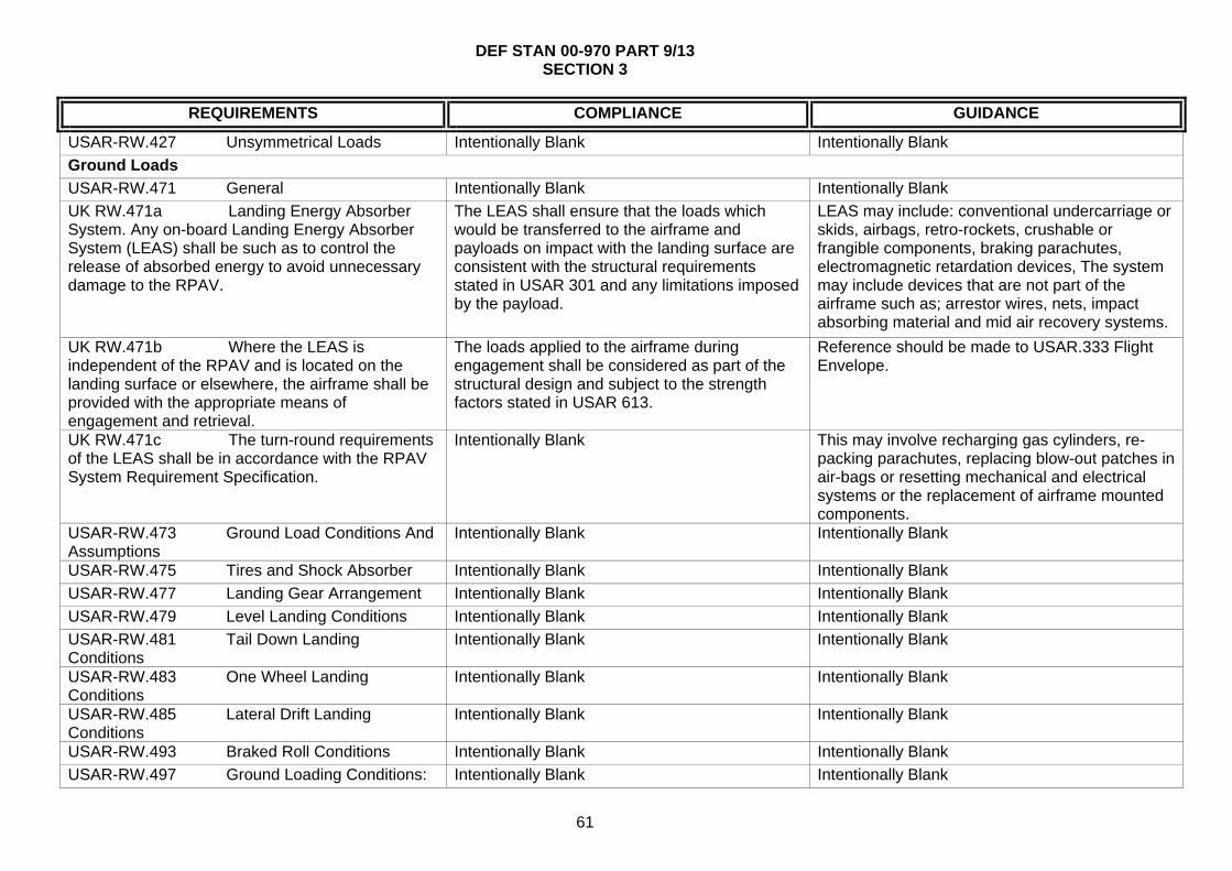
DEF STAN 00-970 PART 9/13 SECTION 3
61
REQUIREMENTS COMPLIANCE GUIDANCE
USAR-RW.427 Unsymmetrical Loads Intentionally Blank Intentionally Blank
Ground Loads
USAR-RW.471 General Intentionally Blank Intentionally Blank
UK RW.471a Landing Energy Absorber System. Any on-board Landing Energy Absorber System (LEAS) shall be such as to control the release of absorbed energy to avoid unnecessary damage to the RPAV.
The LEAS shall ensure that the loads which would be transferred to the airframe and payloads on impact with the landing surface are consistent with the structural requirements stated in USAR 301 and any limitations imposed by the payload.
LEAS may include: conventional undercarriage or skids, airbags, retro-rockets, crushable or frangible components, braking parachutes, electromagnetic retardation devices, The system may include devices that are not part of the airframe such as; arrestor wires, nets, impact absorbing material and mid air recovery systems.
UK RW.471b Where the LEAS is independent of the RPAV and is located on the landing surface or elsewhere, the airframe shall be provided with the appropriate means of engagement and retrieval.
The loads applied to the airframe during engagement shall be considered as part of the structural design and subject to the strength factors stated in USAR 613.
Reference should be made to USAR.333 Flight Envelope.
UK RW.471c The turn-round requirements of the LEAS shall be in accordance with the RPAV System Requirement Specification.
Intentionally Blank This may involve recharging gas cylinders, re-packing parachutes, replacing blow-out patches in air-bags or resetting mechanical and electrical systems or the replacement of airframe mounted components.
USAR-RW.473 Ground Load Conditions And Assumptions
Intentionally Blank Intentionally Blank
USAR-RW.475 Tires and Shock Absorber Intentionally Blank Intentionally Blank
USAR-RW.477 Landing Gear Arrangement Intentionally Blank Intentionally Blank
USAR-RW.479 Level Landing Conditions Intentionally Blank Intentionally Blank
USAR-RW.481 Tail Down Landing Conditions
Intentionally Blank Intentionally Blank
USAR-RW.483 One Wheel Landing Conditions
Intentionally Blank Intentionally Blank
USAR-RW.485 Lateral Drift Landing Conditions
Intentionally Blank Intentionally Blank
USAR-RW.493 Braked Roll Conditions Intentionally Blank Intentionally Blank
USAR-RW.497 Ground Loading Conditions: Intentionally Blank Intentionally Blank

DEF STAN 00-970 PART 9/13 SECTION 3
62
REQUIREMENTS COMPLIANCE GUIDANCE
Landing Gear with Tail Wheels
USAR-RW.501 Ground Loading Conditions: Landing Gear with Skids
Intentionally Blank Intentionally Blank
USAR-RW.505 Ski Landing Conditions Intentionally Blank Intentionally Blank
USAR-RW.U507 Jacking Loads Intentionally Blank Intentionally Blank
USAR-RW.U509 Towing Loads Intentionally Blank Intentionally Blank
Water Loads
USAR-RW.521 Float Landing Conditions Intentionally Blank Intentionally Blank
Main Component Requirements
USAR-RW.547: Main Rotor Structure Intentionally Blank Intentionally Blank
USAR-RW.549 Fuselage, Landing Gear and Rotor Pylon Structures
Intentionally Blank Intentionally Blank
Emergency Landing Conditions
USAR-RW.561 General Intentionally Blank Intentionally Blank
USAR-RW.562 Emergency Landing Dynamic Conditions: Not Applicable
Intentionally Blank Intentionally Blank
USAR-RW.563 Structural Ditching Provisions: Not Applicable
Intentionally Blank Intentionally Blank
Fatigue Evaluation
USAR-RW.U570 General USAR-RW.AMC.570 Intentionally Blank
USAR-RW.571 Fatigue Evaluation of Flight Structure
Intentionally Blank Intentionally Blank

DEF STAN 00-970 PART 9/13 SECTION 3
63
REQUIREMENTS COMPLIANCE GUIDANCE
Subpart D - UAV Design and Construction
General
USAR-RW.601 General Intentionally Blank Intentionally Blank
UK RW.601a Recovery Systems - Where required, the design of the system shall include use of surface restraining systems such as deck locks on board ship.
Airborne system safety factors shall be the subject of agreement between the RPAS Design Organisation and the MOD (PTL) with surface based equipment having an ultimate factor of safety of at least 4.0
Intentionally Blank
UK RW.601b The RPAV shall use lubricant types from the approved list of Def Stan 01-5.
Intentionally Blank Intentionally Blank
UK RW.601c The RPAS shall comply with the requirements of Def Stan 00-970 Part 13 Section 3 requirement 3.11 Protection from the effects of nuclear explosions, laser weapons, chemical and biological warfare agents.
The level of NBC and LASER protection required by any given air vehicle will be defined in the appropriate requirements document and agreed by the MOD (PTL)
The basic Nuclear survivability for military equipment is contained in Def Stan 08-4 Nuclear weapons explosions effects and hardening. Part 2 of the Defence Standard is to be used to determine the effects on materiel, Part 3 identifies simulated environments and Part 4 Chapter 4-05 Table 1 identifies the nuclear environment 1 to be survived. Additional guidance can be found in Def Stan 00-970 Part 13 Section 4 Leaflets 21-24, Def Stan 08-41 Chemical and Biological hardening of military equipment and STANAG 4360 Specifications of paint systems resistant to chemical agents and decontaminants for the protection of land equipment, give requirements for ground based elements of the RPAS.
UK RW.601d The RPAS shall comply with the requirements of Def Stan 00-250 Human Factors for Designers of Systems.
As agreed between the RPAS Design Organisation and the MOD (PTL)
See Def Stan 00-250
USAR-RW.602 Critical Parts USAR-RW.AMC.602 Intentionally Blank
USAR-RW.603 Materials USAR-RW.AMC.603 Intentionally Blank
USAR-RW.605 Fabrication Methods Intentionally Blank Intentionally Blank

DEF STAN 00-970 PART 9/13 SECTION 3
64
REQUIREMENTS COMPLIANCE GUIDANCE
UK RW.605a Where a RPAV is to be constructed in modular form, assembly and dismantling shall be simple and require the minimum of jigging and tooling.
The airframe shall utilise substantiated structural technology. New methods shall be substantiated as part of the qualification test programme and approved by the MOD (PTL). The size and mass of the airframe modules shall be compatible with the manpower, handling aids, storage and logistics stated in the RPAS requirement specification.
Intentionally Blank
USAR-RW.607 Fasteners USAR-RW.AMC.607(b) Intentionally Blank
UK RW.607a Fasteners shall be capable of easy operation by personnel wearing the clothing and working in the environmental conditions stated in the RPAS Requirement Specification.
Intentionally Blank Intentionally Blank
UK RW.607b Fasteners shall be proofed against incorrect closure.
Intentionally Blank Intentionally Blank
USAR-RW.609 Protection Of Structure Intentionally Blank Intentionally Blank
UK RW.609a External colouring and markings of the RPAV shall be in accordance with DAP119A-0601-Series unless otherwise specified in the contract.
The decision to use specific colours shall be agreed by the MOD (PTL). Where a RPAV is of modular construction the nationality and registration mark shall be applied to the fuselage of the vehicle or on the assembly forming the main part of the fuselage.
Where electronics, explosive and close tolerance mechanical devices are fitted inside the fuselage or wings of the RPAV, which could be affected by solar heating absorption, care must be taken to ensure that external coating scheme does not add to the risk of an excessive rise of the internal temperature.
UK RW.609b The colours used for all interior markings and placards shall be in accordance with BS 381C.
Actual colours and markings required shall be agreed prior to contract.
Intentionally Blank
UK RW.609c Air vehicles being regulated under the MAP RA1100 series shall be given a nationality, registration and combatant marking. For other air vehicles a combatant marking only shall be required.
Intentionally Blank To prevent the high usage of registration numbers for target drones, which are eventually destroyed, the recommendation is that a single registration mark (prefix) should be issued by the MAR relating to RPAV type. The Agency or Service operating the equipment will be responsible for the identification of each individual RPAV covered by that registration mark by adding a suffix.

DEF STAN 00-970 PART 9/13 SECTION 3
65
REQUIREMENTS COMPLIANCE GUIDANCE
UK RW.609d RPAVs of modular construction shall have all major assemblies uniquely identified by the manufacturer.
An interchangeable parts register shall be kept for each registered fuselage. The manufacturer shall indelibly mark all components that make up the airframe of the RPAV. Any other assemblies and sub-assemblies that are subjected to fatigue, wear or are interchangeable should also have a record of life.
For the purposes of establishing fatigue life a record should be kept of all exchangeable and replaceable items comprising the RPAV.
USAR-RW.610 Lightning and Static Electricity Protection
USAR-RW.AMC.610 Intentionally Blank
UK RW.610a Electrical Bonding And Protection Against Lightning And Static Electricity
Intentionally Blank See Def Stan 59-113
UK RW.610b Mounting and Protection of Components - Components shall be mounted and protected to established standards.
Components shall comply with the requirements of BS EN 60194 Printed Board Design, Manufacture and Assembly, IPC 2221B, Printed Wiring for Electronic Equipment or similar approved design standard agreed with the MOD (PTL). Subject to the operating conditions of components, conformal coating in accordance with the requirements of BS EN-61086-3-1 shall be used to protect circuit boards except where hermetically sealed enclosures are used.
Where identification of individual components is made in printed circuit or mounting boards, the identification where practicable shall be visible. Where practicable, the polarity markings of polarized components shall be placed adjacent to them.
UK RW.610c Static Charge - Equipment that is sensitive to static charge shall be marked accordingly.
Where the design requires Electro Static Sensitive Devices (ESSD) are fitted, precautions shall be taken to minimize the risk of damage to such devices during operation and maintenance. The design of the equipment shall take into account the need to minimize the risk of damage.
Intentionally Blank
UK RW.610d Programmable Memory Devices - The design of modules shall allow for the re-programming of memory devices.
The application of memory devices shall be designed so that, whenever possible, they may be re-programmed on the parent module. Where this is not practicable, the devices shall be easily removable for re-programming.
Intentionally Blank
USAR-RW.611 Inspection Provisions USAR-RW.AMC.611 Intentionally Blank

DEF STAN 00-970 PART 9/13 SECTION 3
66
REQUIREMENTS COMPLIANCE GUIDANCE
UK RW.611a Access hatches shall be large enough to allow adequate access to installed equipment for maintenance and service by personnel wearing the protective clothing (NBC, cold weather, etc.) specified in the RPAS Requirements Specification.
Parts that require regular inspection for replacement shall be readily accessible and care shall be taken to ensure that no sharp edges or corners are exposed where access is required for servicing and/or maintenance.
Intentionally Blank
USAR-RW.613 Material Strength Properties And Design Values
USAR-RW.AMC.613 Intentionally Blank
UK RW.613a Any permitted repairs shall ensure that the structural and aerodynamic integrity of the airframe is not degraded and that the airworthiness and safety of the operation of the system is not degraded.
Intentionally Blank The RPAV Design Organisation should define the extent and scope of acceptable repairs, taking account of primary, secondary and tertiary structures in addition the RPAS Requirement Specification should state the service conditions in which repairs are expected to be undertaken.
USAR-RW.619 Special Factors Intentionally Blank Intentionally Blank
USAR-RW.621 Casting Factors Intentionally Blank Intentionally Blank
USAR-RW.623 Bearing Factors Intentionally Blank Intentionally Blank
USAR-RW.625 Fitting Factors Intentionally Blank Intentionally Blank
USAR-RW.629 Flutter Intentionally Blank Intentionally Blank
USAR-RW.631 Bird Strike Intentionally Blank Intentionally Blank
UK RW.631(a) Refer to UK National Reservations in part 1 - 1.2.2.d.(1) The Applicant shall consider the hazardous effects of birdstrike on the RPAS when operated in accordance with the DUS.
The safety case should include the effects of failure of the RPAS and the control link as a result of birdstrike effects.
Intentionally Blank
USAR-RW.635 Ground Equipment Affecting Flight Safety
Intentionally Blank Intentionally Blank
Rotors
USAR-RW.653 Pressure Venting and Drainage of Rotor Blades
Intentionally Blank Intentionally Blank

DEF STAN 00-970 PART 9/13 SECTION 3
67
REQUIREMENTS COMPLIANCE GUIDANCE
UK RW.653a A specification for any rotors used in the RPAV propulsion system shall be written to meet all the relevant requirements of Def Stan 00-970 Part 7.
Compliance shall be demonstrated against relevant sections within Def Stan 00-970 Part 7 and agreed with the MOD (PTL)
Intentionally Blank
UK RW.653b Consideration shall be given to safety of launch personnel when starting rotorcraft engines.
Intentionally Blank This is particularly relevant for systems that have low-level rotor blades where launch personnel are required to come into close proximity to the rotor blades therefore to ensure safety of launch personnel, starting of rotorcraft should be remote, where possible.
USAR-RW.659 Mass Balance Intentionally Blank Intentionally Blank
USAR-RW.661 Rotor Blade Clearance Intentionally Blank Intentionally Blank
USAR-RW.663 Ground Resonance Prevention Means
Intentionally Blank Intentionally Blank
Control Systems
USAR-RW.671 General USAR-RW.AMC.671 Intentionally Blank
USAR-RW.672 Power Operated Systems Intentionally Blank Intentionally Blank
USAR-RW.674 Interconnected Controls Intentionally Blank Intentionally Blank
USAR-RW.675 Stops Intentionally Blank Intentionally Blank
USAR-RW.679 Control Locks Intentionally Blank Intentionally Blank
USAR-RW.681 Limit Load Static Tests Intentionally Blank Intentionally Blank
USAR-RW.683 Operation Tests USAR-RW.AMC.683 Intentionally Blank
USAR-RW.685 Control System Details Intentionally Blank Intentionally Blank
USAR-RW.687 Spring Devices Intentionally Blank Intentionally Blank
USAR-RW.691 Autorotation Control Mechanism
Intentionally Blank Intentionally Blank
USAR-RW.695 Power Boost and Power-Operated Control System
Intentionally Blank Intentionally Blank
Landing Gear
USAR-RW.723 Shock Absorption Tests Intentionally Blank Intentionally Blank
USAR-RW.725 Limit Drop Test Intentionally Blank Intentionally Blank

DEF STAN 00-970 PART 9/13 SECTION 3
68
REQUIREMENTS COMPLIANCE GUIDANCE
USAR-RW.727 Reserve Energy Absorption Drop Tests
Intentionally Blank Intentionally Blank
USAR-RW.729 Landing Gear Extension And Retraction System
Intentionally Blank Intentionally Blank
USAR-RW.731 Wheels Intentionally Blank Intentionally Blank
USAR-RW.733 Tyres Intentionally Blank Intentionally Blank
USAR-RW.735 Brakes Intentionally Blank Intentionally Blank
USAR-RW.737 Skis Intentionally Blank Intentionally Blank
Floats and Hulls
USAR-RW.751 Main Float Buoyancy Intentionally Blank Intentionally Blank
USAR-RW.753 Main Float Design Intentionally Blank Intentionally Blank
USAR-RW.755 Hulls Intentionally Blank Intentionally Blank
Payload and Equipment Accommodations
USAR-RW.771 Pilot Compartment: Not Applicable in this Subpart (See USAR-RW.U1703)
Intentionally Blank Intentionally Blank
USAR-RW.773 Pilots Compartment View: Not Applicable in this Subpart (See USAR-RW.1721(a))
Intentionally Blank Intentionally Blank
USAR-RW.775 Windshields and Windows: Not Applicable
Intentionally Blank Intentionally Blank
USAR-RW.777 Cockpit Controls: Not Applicable
Intentionally Blank Intentionally Blank
USAR-RW.779 Motion and Effect of Controls: Not Applicable in this Subpart (See USAR-RW.U1735)
Intentionally Blank Intentionally Blank
USAR-RW.783 Payload or Equipment Doors And Hatches
Intentionally Blank Intentionally Blank
USAR-RW.785 Seats, Berths, Safety Belts and harnesses: Not Applicable
Intentionally Blank Intentionally Blank
USAR-RW.787 Cargo/Payload Compartments
Intentionally Blank Intentionally Blank
USAR-RW.801 Ditching: Not Applicable Intentionally Blank Intentionally Blank

DEF STAN 00-970 PART 9/13 SECTION 3
69
REQUIREMENTS COMPLIANCE GUIDANCE
USAR-RW.805 Flight Crew Emergency Exits: Not Applicable
Intentionally Blank Intentionally Blank
USAR-RW.807 Emergency Exits: Not Applicable
Intentionally Blank Intentionally Blank
USAR-RW.831 Ventilation: Not Applicable Intentionally Blank Intentionally Blank
USAR-RW.833 Heaters Intentionally Blank Intentionally Blank
UK RW.833a Refer to UK National Reservations in part 1 - 1.2.2.d.(2)
Intentionally Blank Intentionally Blank
USAR-RW.841 Pressurised Compartments Intentionally Blank Intentionally Blank
USAR-RW.843 Pressurisation Tests Intentionally Blank Intentionally Blank
Fire Protection
USAR-RW.850 Fire Protection - General USAR-RW.AMC.850 Intentionally Blank
USAR-RW.853 Compartment Interiors: Not Applicable
Intentionally Blank Intentionally Blank
USAR-RW.855 Cargo Compartments Intentionally Blank Intentionally Blank
USAR-RW.859 Heating Systems: Not Applicable
Intentionally Blank Intentionally Blank
USAR-RW.861 Fire Protection of Structure, Controls and other Parts
Intentionally Blank Intentionally Blank
USAR-RW.863 Flammable Fluid Fire Protection
Intentionally Blank Intentionally Blank
External Loads
USAR-RW.865 External Loads Intentionally Blank Intentionally Blank
Miscellaneous
USAR-RW.871 Levelling Means Intentionally Blank Intentionally Blank
USAR-RW.873 Ballast Provisions Intentionally Blank Intentionally Blank

DEF STAN 00-970 PART 9/13 SECTION 3
70
REQUIREMENTS COMPLIANCE GUIDANCE
Subpart E - UAV Powerplant
General
USAR-RW.901 Installation Intentionally Blank Intentionally Blank
UK RW.901a For RPAVs utilising turbine / piston engines and rocket motor installations a power plant specification shall be produced based upon the appropriate standards that apply to manned aircraft power plants (in particular Def Stan 00-970 Part 1 Section 5) and associated sub-systems. (See UK 903)
Intentionally Blank Intentionally Blank
UK RW.901b For RPAVs that utilise other methods of propulsion, a power plant specification that provides levels of design integrity and safety consistent with Def Stan 00-970 Part 11 and Part 1 Section 5 shall be produced.
Intentionally Blank Intentionally Blank
UK RW.901c The power plant specification developed to comply with UK 901a or UK 901b shall adequately address any potential hazards or failures modes that could result from operational requirements over and above those for manned aircraft.
Intentionally Blank For example, RPAV power plants may be required to operate under significantly higher G loading than those for manned aircraft.
UK RW.901d The power plant shall be of such a design that it enables the RPAV to comply with operational, reliability, maintainability, environmental and safety requirements defined in the RPAS Requirements Specification.
Intentionally Blank The power plant is defined as the integrated assemblage of components and subsystems that provides the power in the appropriate form for flight propulsion, lift (rotorcraft and VTOL) and auxiliary systems such as electrical power generation. The engine is defined to be the core component that provides motive power and can be of the following configurations gas turbine, reciprocating internal combustion, reciprocating compressed gas, rotary internal combustion ramjet, pulsejet or electric motors. The power plant should have the potential to deliver
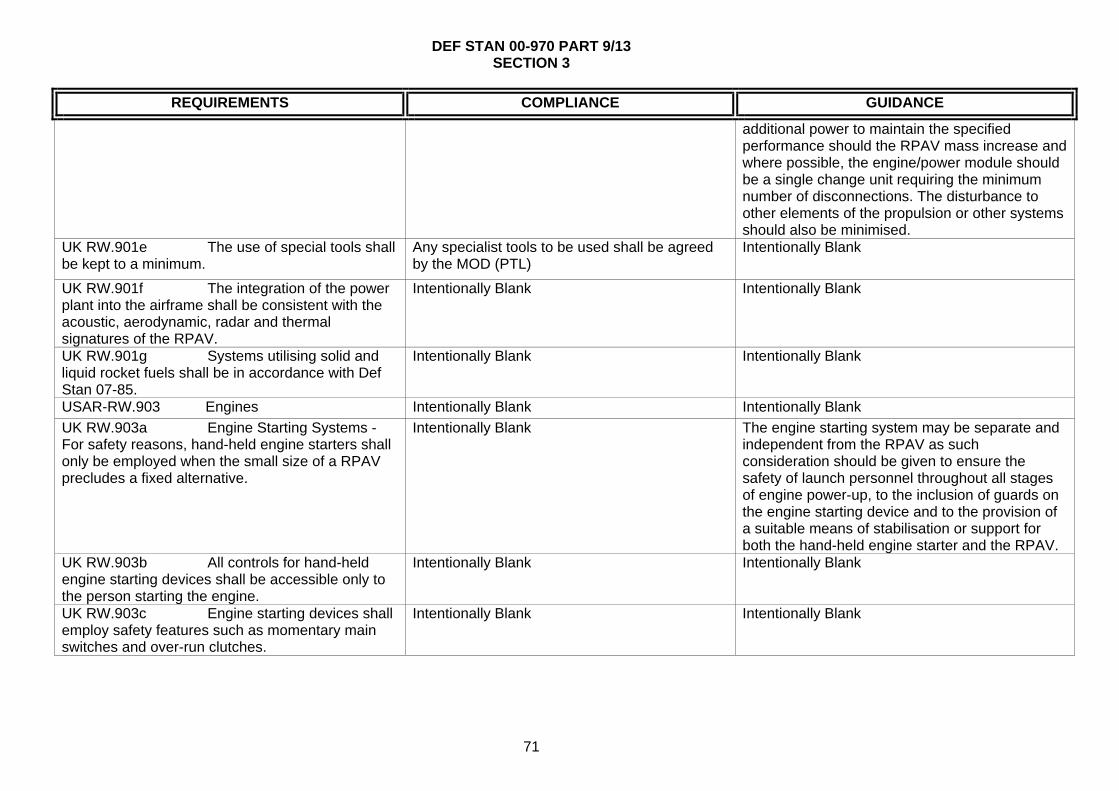
DEF STAN 00-970 PART 9/13 SECTION 3
71
REQUIREMENTS COMPLIANCE GUIDANCE
additional power to maintain the specified performance should the RPAV mass increase and where possible, the engine/power module should be a single change unit requiring the minimum number of disconnections. The disturbance to other elements of the propulsion or other systems should also be minimised.
UK RW.901e The use of special tools shall be kept to a minimum.
Any specialist tools to be used shall be agreed by the MOD (PTL)
Intentionally Blank
UK RW.901f The integration of the power plant into the airframe shall be consistent with the acoustic, aerodynamic, radar and thermal signatures of the RPAV.
Intentionally Blank Intentionally Blank
UK RW.901g Systems utilising solid and liquid rocket fuels shall be in accordance with Def Stan 07-85.
Intentionally Blank Intentionally Blank
USAR-RW.903 Engines Intentionally Blank Intentionally Blank
UK RW.903a Engine Starting Systems - For safety reasons, hand-held engine starters shall only be employed when the small size of a RPAV precludes a fixed alternative.
Intentionally Blank The engine starting system may be separate and independent from the RPAV as such consideration should be given to ensure the safety of launch personnel throughout all stages of engine power-up, to the inclusion of guards on the engine starting device and to the provision of a suitable means of stabilisation or support for both the hand-held engine starter and the RPAV.
UK RW.903b All controls for hand-held engine starting devices shall be accessible only to the person starting the engine.
Intentionally Blank Intentionally Blank
UK RW.903c Engine starting devices shall employ safety features such as momentary main switches and over-run clutches.
Intentionally Blank Intentionally Blank

DEF STAN 00-970 PART 9/13 SECTION 3
72
REQUIREMENTS COMPLIANCE GUIDANCE
UK RW.903d For turbine engines, reference shall be made to Def Stan 00-970 Part 1 Sections 5 and 8, Part 11 and CS-E.
Compliance shall be demonstrated against relevant sections within of Def Stan 00-970 Part 1 Sections 5 and 8, and Part 11 and agreed with the MOD (PTL).
Intentionally Blank
UK RW.903e For piston engines, reference shall be made to CS-E and to FAR 33.
Compliance shall be demonstrated against the engine specification requirements within CS-E and agreed with the MOD (PTL).
Intentionally Blank
UK RW.903f For rocket motors, reference shall be made to the requirements set out in Def Stan 07-85.
Compliance shall be demonstrated against the engine specification sections within Def Stan 07-85 and agreed with the MOD (PTL)
Intentionally Blank
UK RW.903g Engine environmental impact shall be minimised.
The design shall be carried out in accordance with ISO 14001 principles.
Intentionally Blank
UK RW.903h The engine shall be mounted in the RPAV in such a manner as to keep transmitted vibration outside frequencies and amplitudes that would have deleterious effects on the integrity and performance of the RPAV structures, mechanisms, avionics and payload or harmful effects to personnel (for example during hand held launch) or the general public.
The RPAV Design Organisation and the RPAV Power plant Design Organisation shall agree vibration limits caused by the interaction of the power plant and the RPAV in all configurations such that the performance or safety requirements of the RPAV stated in the RPAS Requirement Specification are not unacceptably compromised.
Intentionally Blank
UK RW.903j The use of novel engine design or configurations shall be approved by the MOD (PTL)
Novel engine designs shall meet the requirements of Def Stan 00-970 Part 11 and Part 1 Section 5.
It should be noted that novel engine configurations will be subjected to the certification processes as defined in Def Stan 00-970 part 11 and Map RA 5000 series.
UK RW.903k Sufficient power shall be available to cover the maximum load conditions of the RPAV.
A power requirement calculation shall be performed.
Consideration should be given to the inclusion of a tolerance for potential future development. The power requirement calculation should take into account electrical, mechanical, pneumatic or hydraulic subsystems and possible payloads.
UK RW.903l Power Loading - Operational degradation due to partial loss of power shall be managed.
Critical systems shall be identified and priority given to maintaining their integrity.
The critical systems may be considered to be the RPAV flight control and safety systems and Consideration should be given to selective load shedding for operational contingencies.
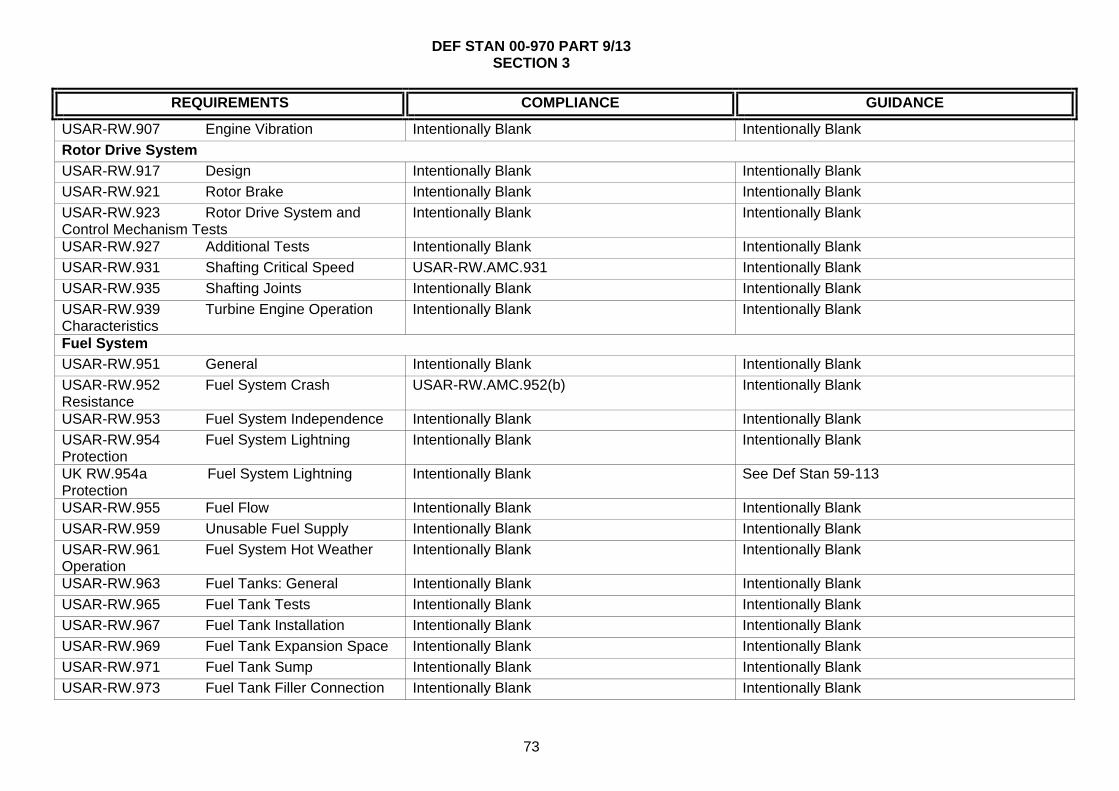
DEF STAN 00-970 PART 9/13 SECTION 3
73
REQUIREMENTS COMPLIANCE GUIDANCE
USAR-RW.907 Engine Vibration Intentionally Blank Intentionally Blank
Rotor Drive System
USAR-RW.917 Design Intentionally Blank Intentionally Blank
USAR-RW.921 Rotor Brake Intentionally Blank Intentionally Blank
USAR-RW.923 Rotor Drive System and Control Mechanism Tests
Intentionally Blank Intentionally Blank
USAR-RW.927 Additional Tests Intentionally Blank Intentionally Blank
USAR-RW.931 Shafting Critical Speed USAR-RW.AMC.931 Intentionally Blank
USAR-RW.935 Shafting Joints Intentionally Blank Intentionally Blank
USAR-RW.939 Turbine Engine Operation Characteristics
Intentionally Blank Intentionally Blank
Fuel System
USAR-RW.951 General Intentionally Blank Intentionally Blank
USAR-RW.952 Fuel System Crash Resistance
USAR-RW.AMC.952(b) Intentionally Blank
USAR-RW.953 Fuel System Independence Intentionally Blank Intentionally Blank
USAR-RW.954 Fuel System Lightning Protection
Intentionally Blank Intentionally Blank
UK RW.954a Fuel System Lightning Protection
Intentionally Blank See Def Stan 59-113
USAR-RW.955 Fuel Flow Intentionally Blank Intentionally Blank
USAR-RW.959 Unusable Fuel Supply Intentionally Blank Intentionally Blank
USAR-RW.961 Fuel System Hot Weather Operation
Intentionally Blank Intentionally Blank
USAR-RW.963 Fuel Tanks: General Intentionally Blank Intentionally Blank
USAR-RW.965 Fuel Tank Tests Intentionally Blank Intentionally Blank
USAR-RW.967 Fuel Tank Installation Intentionally Blank Intentionally Blank
USAR-RW.969 Fuel Tank Expansion Space Intentionally Blank Intentionally Blank
USAR-RW.971 Fuel Tank Sump Intentionally Blank Intentionally Blank
USAR-RW.973 Fuel Tank Filler Connection Intentionally Blank Intentionally Blank

DEF STAN 00-970 PART 9/13 SECTION 3
74
REQUIREMENTS COMPLIANCE GUIDANCE
USAR-RW.975 Fuel Tank Vents Intentionally Blank Intentionally Blank
USAR-RW.977 Fuel Tank Outlet Intentionally Blank Intentionally Blank
Fuel System Components
USAR-RW.991 Fuel Pumps Intentionally Blank Intentionally Blank
USAR-RW.993 Fuel System Lines And Fittings
Intentionally Blank Intentionally Blank
USAR-RW.995 Fuel Valves And Controls (See also USAR-RW.U1743 Fuel Controls)
Intentionally Blank Intentionally Blank
USAR-RW.997 Fuel Strainer Or Filter Intentionally Blank Intentionally Blank
USAR-RW.999 Fuel System Drains USAR-RW.AMC.999 Intentionally Blank
Oil System
USAR-RW.1011 General Intentionally Blank Intentionally Blank
USAR-RW.1013 Oil Tanks Intentionally Blank Intentionally Blank
USAR-RW.1015 Oil Tank Tests Intentionally Blank Intentionally Blank
USAR-RW.1017 Oil Lines And Fittings Intentionally Blank Intentionally Blank
USAR-RW.1019 Oil Strainer Or Filter Intentionally Blank Intentionally Blank
USAR-RW.1021 Oil System Drains Intentionally Blank Intentionally Blank
USAR-RW.1027 Transmissions and Gearboxes: General
Intentionally Blank Intentionally Blank
Cooling
USAR-RW.1041 General Intentionally Blank Intentionally Blank
UK RW.1041a The location of any cooling air apertures, ducts or radiators shall be consistent with the requirements for acoustic, radar, thermal and visual signatures.
Intentionally Blank Intentionally Blank
USAR-RW.1043 Cooling Tests Intentionally Blank Intentionally Blank
USAR-RW.1045 Cooling Test Procedure Intentionally Blank Intentionally Blank
Induction System
USAR-RW.1091 Air Induction Intentionally Blank Intentionally Blank
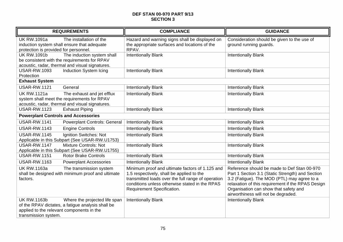
DEF STAN 00-970 PART 9/13 SECTION 3
75
REQUIREMENTS COMPLIANCE GUIDANCE
UK RW.1091a The installation of the induction system shall ensure that adequate protection is provided for personnel.
Hazard and warning signs shall be displayed on the appropriate surfaces and locations of the RPAV.
Consideration should be given to the use of ground running guards.
UK RW.1091b The induction system shall be consistent with the requirements for RPAV acoustic, radar, thermal and visual signatures.
Intentionally Blank Intentionally Blank
USAR-RW.1093 Induction System Icing Protection
Intentionally Blank Intentionally Blank
Exhaust System
USAR-RW.1121 General Intentionally Blank Intentionally Blank
UK RW.1121a The exhaust and jet efflux system shall meet the requirements for RPAV acoustic, radar, thermal and visual signatures.
Intentionally Blank Intentionally Blank
USAR-RW.1123 Exhaust Piping Intentionally Blank Intentionally Blank
Powerplant Controls and Accessories
USAR-RW.1141 Powerplant Controls: General Intentionally Blank Intentionally Blank
USAR-RW.1143 Engine Controls Intentionally Blank Intentionally Blank
USAR-RW.1145 Ignition Switches: Not Applicable in this Subpart (See USAR-RW.U1753)
Intentionally Blank Intentionally Blank
USAR-RW.1147 Mixture Controls: Not Applicable in this Subpart (See USAR-RW.U1755)
Intentionally Blank Intentionally Blank
USAR-RW.1151 Rotor Brake Controls Intentionally Blank Intentionally Blank
USAR-RW.1163 Powerplant Accessories Intentionally Blank Intentionally Blank
UK RW.1163a The transmission system shall be designed with minimum proof and ultimate factors.
Minimum proof and ultimate factors of 1.125 and 1.5 respectively, shall be applied to the transmitted loads over the full range of operation conditions unless otherwise stated in the RPAS Requirement Specification.
Reference should be made to Def Stan 00-970 Part 1 Section 3.1 (Static Strength) and Section 3.2 (Fatigue). The MOD (PTL) may agree to a relaxation of this requirement if the RPAS Design Organisation can show that safety and airworthiness will not be degraded.
UK RW.1163b Where the projected life span of the RPAV dictates, a fatigue analysis shall be applied to the relevant components in the transmission system.
Intentionally Blank Intentionally Blank

DEF STAN 00-970 PART 9/13 SECTION 3
76
REQUIREMENTS COMPLIANCE GUIDANCE
UK RW.1163c For rotorcraft employing extended drive shafts, means shall be provided to ensure that no dangerous torsional or flexural vibration or whirling can occur throughout the torque and RPM range.
Intentionally Blank Intentionally Blank
Powerplant Fire Protection
USAR-RW.1183 Lines, Fittings And Components
Intentionally Blank Intentionally Blank
USAR-RW.1185 Flammable Fluids Intentionally Blank Intentionally Blank
USAR-RW.1187 Ventilation and Drainage Intentionally Blank Intentionally Blank
USAR-RW.1189 Shut-Off Means Intentionally Blank Intentionally Blank
USAR-RW.1191 Firewalls Intentionally Blank Intentionally Blank
USAR-RW.1193 Cowling And Engine Compartment Covering
Intentionally Blank Intentionally Blank
USAR-RW.1194 Other Surfaces Intentionally Blank Intentionally Blank
USAR-RW.1195 Fire Detector Systems Intentionally Blank Intentionally Blank

DEF STAN 00-970 PART 9/13 SECTION 3
77
REQUIREMENTS COMPLIANCE GUIDANCE
Subpart F - Equipment
General
USAR-RW.1301 Function And Installation Intentionally Blank Intentionally Blank
UK RW.1301a The RPAS shall comply with the requirements of Def Stan 00-40 Reliability and Maintainability (R & M)
The equipment R & M programme shall be conducted in accordance with the series of Defence Standards in the Def Stan 00-40 to 00-44 range, as agreed between the RPAS Design Organisation and the MOD (PTL)
The terms applicable to this clause are defined in Allied Reliability and Maintainability Publication (ARMP) 7 and Def Stan 00-49. Within this Defence Standard, the term R & M is used as a standard top level abbreviation, and embraces all of the following terms: reliability, maintainability, testability, durability and availability. Guidance on the achievement of testability requirements can be gained from Def Stan 00-42 Part 4. Pre-flight test requirements should be derived from reliability and mission success requirements.
UK RW.1301b As far as practicable, fuels, oils and lubricants employed in the launch and recovery systems shall be selected from Def Stan 01-5.
The Design Organisation shall identify any fuels, oils or lubricants needed which are not covered in Def Stan 01-5. The agreement of the MOD (PTL) shall be obtained before fuels, oils or lubricants not in Def Stan 01-5 are used.
Intentionally Blank
UK RW.1301c Installation of Explosive Devices - All explosive devices to be fitted to the RPAV shall be approved by the relevant MOD authorities, shall be installed so as to be easily accessible and shall not require excessive handling during installation. Protective sheaths or grommets shall be used where there is the likelihood of damage being caused by handling or vibration. Electrical circuits associated with the installation of explosive devices shall conform to Def Stan 00-970 Part 1, Section 6 Clause 6.6
Particular attention shall be paid to protecting the insulation of the circuits connected to explosives.
Consideration should be given to making the component in which the explosive is installed readily replaceable so that handling of the explosive charge can be carried out under servicing bay conditions. For RPAS that have a maritime role and are required to operate from naval craft reference should be made to Naval Publication JSP 862 and Def Stan 00-101.
USAR-RW.1303 Flight and Navigation Intentionally Blank Intentionally Blank

DEF STAN 00-970 PART 9/13 SECTION 3
78
REQUIREMENTS COMPLIANCE GUIDANCE
Instruments: Not Applicable in this Subpart (See USAR-RW.F1723 Flight and Navigation Data) USAR-RW.1304 Navigation Architecture Intentionally Blank Intentionally Blank
USAR-RW.1305 Powerplant Instruments: Not Applicable in this Subpart (See USAR-RW.U1725 Powerplant Data)
Intentionally Blank Intentionally Blank
USAR-RW.1307 Miscellaneous Equipment Intentionally Blank Intentionally Blank
USAR-RW.1309 Equipment, Systems And Installations
USAR-RW.AMC.1309(b) Intentionally Blank
UK RW.1309a Safety Management Safety Management for all aspects of the RPAS to be in accordance with Def Stan 00-56, or an agreed equivalent standard.
Intentionally Blank
USAR-RW.U1317 High-Intensity Radiated Fields (HIRF) Protection
USAR-RW.AMC.1317 Intentionally Blank
USAR-RW.1321 Arrangement and Visibility Intentionally Blank Intentionally Blank
USAR-RW.1322 Warning Control and Advisory Lights
Intentionally Blank Intentionally Blank
Measuring Devices Installation
USAR-RW.1323 Airspeed Measuring Device Intentionally Blank Intentionally Blank
USAR-RW.1325 Static Pressure Systems Intentionally Blank Intentionally Blank
USAR-RW.1327 Magnetic Heading Measuring Device
Intentionally Blank Intentionally Blank
UK RW.1327a Installation of Magnetic Compass - The design shall take into account the need for implementing and carrying out De-magnetisation, Compass Safe Distance and Compass Swing Accuracy.
Information contained in Def Stan 00-970 Part. 1 Section 6.4 and BS G 262 shall be used to satisfy these requirements.
Intentionally Blank
USAR-RW.1329 Flight Control System USAR-RW.AMC.1329 Intentionally Blank

DEF STAN 00-970 PART 9/13 SECTION 3
79
REQUIREMENTS COMPLIANCE GUIDANCE
UK RW.1329a Reversionary navigation capability shall be provided to ensure safety of flight.
The needs for, and performance requirements of, separate navigation systems shall be established in the RPAS Safety Case and specified in the RPAS Requirements Specification. Alternative navigation sensors listed under Guidance shall be considered.
The following should be considered as reversionary navigation sensors: Dead reckoning from fluxgate and air data, communication/data links range and bearing, Terrain referenced navigation and scene matching navigation. The choice may depend on terminal navigation requirements derived from mission success criteria.
USAR-RW.1335 Flight Director Systems: Not Applicable in this Subpart (See USAR-RW.U1790 UAV RW Mode of Control Indicator)
Intentionally Blank Intentionally Blank
USAR-RW.1337 Powerplant Installation Measuring Device
Intentionally Blank Intentionally Blank
Electrical Systems and Equipment
USAR-RW.1351 General USAR-RW.AMC.1351(a)(2) Intentionally Blank
UK RW.1351a Electrical Systems and Wiring - The requirements of Def Stan 00-970 Part 1 Section 6 Leaflets 4, 14, 15, 16, and 35 shall be considered.
These requirements shall supplement the CS 1351 and 1353 requirements except where agreed with the MOD (PTL)
Intentionally Blank
UK RW.1351b Electrical Systems and Wiring - The installation shall be designed for ease of maintenance.
Intentionally Blank Intentionally Blank
UK RW.1351c If the air vehicle carries a payload that is designed to be jettisoned or released on command, the electrical installation of the arming and release system shall conform to Def Stan 00-970 Part 13 Sections 3.1 (Armament Installations – General), 3.2 (Armament Control System) and 3.14 (Integration of Stores)
Intentionally Blank Intentionally Blank
UK RW.1351d Electrical Interfaces - Established standards such as RS 422, MIL STD 1760 and MIL STD 1553B shall be used wherever practicable.
Intentionally Blank Intentionally Blank
USAR-RW.1353 Storage Battery Or Intentionally Blank Intentionally Blank

DEF STAN 00-970 PART 9/13 SECTION 3
80
REQUIREMENTS COMPLIANCE GUIDANCE
Emergency Power Supply Design And Installation
UK RW.1353a Refer to UK National Reservations in part 1 - 1.2.2.d.(3)
Intentionally Blank Intentionally Blank
UK RW.1353b Other fuels and Energy Sources - Where unconventional energy sources are utilised, they shall not hazard personnel or adversely affect the air vehicle.
Where unconventional energy sources are proposed they shall be agreed by the MOD (PTL).
Unconventional energy sources currently include the use of solar energy, microwave energy and regeneration systems. It should be noted that such systems might, in due course, be considered conventional.
UK RW.1353c The RPAS shall comply with the requirements of Def Stan 59-411 - Electromagnetic Compatibility, for EMC and ECM, and Def Stan 59-113 for Lightning protection.
The control plan, requirements, trials and Tests shall be agreed by the MOD (PTL)
The achievement of EMC in a RPAS is a relatively complex matter because of the different nature of the requirement for the Air Vehicle, Ground Control Elements and the Communication/Data Links between the two and to the “outside world” in respect of a relatively “small” RPAS. The differing requirements for Sea, Air and Land systems should be taken into account. DE3A (Contact details in Def Stan 59-411) should be consulted, being able to offer E3 Functional Assurance at all stages of a project.
USAR-RW.1357 Circuit Protection Devices Intentionally Blank Intentionally Blank
USAR-RW.1361 Master Switch Arrangement USAR-RW.AMC.1361 Intentionally Blank
USAR-RW.1365 Electric Cables And Equipment
Intentionally Blank Intentionally Blank
UK RW.1365a Cable runs and connector orientation shall be such as to enable easy and correct connection and disconnection of units in the field.
Intentionally Blank RPAVs may be smaller than their manned equivalents and the environment for servicing may be more severe. Good design of cable runs can obviate damage during servicing.
USAR-RW.1367 Switches Intentionally Blank Intentionally Blank
Lights
USAR-RW.1381 Instrument Lights: Not Applicable in this Subpart (See USAR-RW.1705 and USAR-RW.U1721(e))
Intentionally Blank Intentionally Blank
USAR-RW.1383 Taxi And Landing Lights Intentionally Blank Intentionally Blank

DEF STAN 00-970 PART 9/13 SECTION 3
81
REQUIREMENTS COMPLIANCE GUIDANCE
USAR-RW.1385 Position Light System Installation
Intentionally Blank Intentionally Blank
USAR-RW.1387 Position Light System Dihedral Angles
Intentionally Blank Intentionally Blank
USAR-RW.1389 Position Light Distribution And Intensities
Intentionally Blank Intentionally Blank
USAR-RW.1391 Minimum Intensities In The Horizontal Plane Of Forward and Rear Position Lights
Intentionally Blank Intentionally Blank
USAR-RW.1393 Minimum Intensities In Any Vertical Plane Of Forward and Rear Position Lights
Intentionally Blank Intentionally Blank
USAR-RW.1395 Maximum Intensities In Overlapping Beams Of Forward and Rear Position Lights
Intentionally Blank Intentionally Blank
USAR-RW.1397 Colour Specifications Intentionally Blank Intentionally Blank
USAR-RW.1399 Riding Light Intentionally Blank Intentionally Blank
USAR-RW.1401 Anti-Collision Light System Intentionally Blank Intentionally Blank
Safety equipment and Emergency Capability
USAR-RW.1411 General: Not Applicable Intentionally Blank Intentionally Blank
USAR-RW.U1412 Emergency Recovery Capability
USAR AMC.1412 Intentionally Blank
UK RW.U1412a Flight Termination - Safety and Reliability - The RPAS Requirements Specification shall identify any operational scenarios where the normal function of the FTS is to be inhibited.
Intentionally Blank Conditions in which it may be necessary to inhibit the operation of the FTS may include the period immediately after launch when it is necessary to achieve a safe separation distance from the launch platform, any period during recovery or retrieval when operation of the FTS could increase the risk to personnel or third parties being overflown or within the vicinity or if launch has been inhibited after propulsion system ignition.
UK RW.U1412b Flight Termination - The RPAS Requirement Specification shall state the extent to which the FTS shall be resistant to internal
See Clause UK 1353b Intentionally Blank

DEF STAN 00-970 PART 9/13 SECTION 3
82
REQUIREMENTS COMPLIANCE GUIDANCE
and external interference including jamming. USAR-RW.1413 Safety Belt: Not Applicable Intentionally Blank Intentionally Blank
USAR-RW.1415 Ditching Equipment: Not Applicable
Intentionally Blank Intentionally Blank
USAR-RW.1419 Ice Protection Intentionally Blank Intentionally Blank
Miscellaneous Equipment
USAR-RW.1431 Electronic Equipment USAR-RW.AMC 1431 Intentionally Blank
UK RW.1431a Radio and Radar Installations - Radio and radar installations shall be such that when utilising the RPAV power source they shall achieve optimum specified performance, even when subjected to their most severe environmental conditions.
The location of the aerial(s) on the RPAV shall take into account: signal polarisation, required radiation pattern, electromagnetic interference, multipath signal reflections, optimised radiation efficiency, matched aerials (if homing is a requirement), and the ability to withstand mechanical loading and damage.
The Radio and Radar installations comprise those items of equipment including LRUs that form the communication and guidance system of the RPAV and includes the aerial design. It is recommended that the following Defence Standards shall be referred to where necessary: Def Stan 00-18 - Avionic Data Transmission, Def Stan 00-56 – Safety Management Requirements for Defence Systems and IEC TS 62239-1 Process management for avionics. Management plan. Preparation and maintenance of an electronic components management plan.
USAR-RW.1435 Hydraulic Systems Intentionally Blank Intentionally Blank
USAR-RW.1457 Voice Recorder: Not Applicable in this Subpart (See USAR-RW.U1709)
Intentionally Blank Intentionally Blank
USAR-RW.1459 Rotorcraft UAV Onboard Flight Recorders
USAR-RW.AMC.1459 Intentionally Blank
USAR-RW.1461 Equipment Containing High Energy Rotors
Intentionally Blank Intentionally Blank
USAR-RW.U1481 Payloads USAR-RW.AMC.1481 Intentionally Blank
UK RW.U1481a The integration of the payload shall be consistent with the specified RPAV acoustic, optical, radar and thermal signatures.
Intentionally Blank Intentionally Blank
UK RW.U1481b Re-configuration of the payload shall not adversely affect EMC of the RPAV.
Tests shall be performed to demonstrate that the EMC characteristics remain within the specified parameters.
Reference should be made to: STANAG 4145, AECTP-250, AECTP500 and Defence Standards 59-411 and 08-4.

DEF STAN 00-970 PART 9/13 SECTION 3
83
REQUIREMENTS COMPLIANCE GUIDANCE
UK RW.U1481c The installation, deployment and operation of dispensing payloads shall be consistent with the relevant chapters/clauses of the Def Stan 07-85 and Def Stan 00-970 Part 1.
Intentionally Blank Dispensable payloads may be, but are not limited to, Weapons payloads such as missiles, torpedoes or laser-guided bombs. Non-Lethal dispensable payloads may include remote or unattended ground sensors, leaflets as part of a psychological operations, or humanitarian aid. Consideration should be given to the deployment of the payload as well as the installation, with particular attention to acceleration loads on the weapon/airframe interface during air vehicle manoeuvres.
UK RW.U1481d Dispensing Payloads - Safe separation shall be achieved under all defined operational release conditions.
Release systems shall be fail-safe in accordance with Def Stan 07-85.
Intentionally Blank
UK RW.U1481e Final arming of the dispensing payload release or operating system shall be commanded via the control link during flight.
Intentionally Blank Arming of the system may include progressive stages, such as removal of ground safety pins and connection of services.
UK RW.U1481f Dispensing Payloads - In the event of the payload misfiring or failing to operate, the RPAV must be capable of safe recovery, cut down, or disposal of the payload.
The system shall ensure the RPAV-pilot(s)/Commander have verification of payload operation (successful or not) at each phase.
The method employed for safe recovery, cut down, or disposal of the payload is dependent upon the nature of the payload and operating scenario.
USAR-RW.U1485 Environmental Control System (ECS)
USAR AMC.1485 Intentionally Blank
Automatic Take-Off, Taxi, Landing
USAR-RW.U1490 General Intentionally Blank Intentionally Blank
USAR-RW.U1492 Manual Abort Function Intentionally Blank Intentionally Blank
USAR-RW.U1494 Automatic Taxi System Intentionally Blank Intentionally Blank

DEF STAN 00-970 PART 9/13 SECTION 3
84
REQUIREMENTS COMPLIANCE GUIDANCE
Subpart G - Operating Limitations and Information
General
USAR-RW.1501 General Intentionally Blank Intentionally Blank
USAR-RW.1503 Airspeed Limitations: General Intentionally Blank Intentionally Blank
USAR-RW.1505 Never Exceed Speed Intentionally Blank Intentionally Blank
USAR-RW.1509 Rotor Speed Intentionally Blank Intentionally Blank
USAR-RW.1519 Weight And Centre Or Gravity
Intentionally Blank Intentionally Blank
USAR-RW.1521 Powerplant Limitations Intentionally Blank Intentionally Blank
USAR-RW.1523 Minimum Flight Crew: Not Applicable in this Subpart (See USAR-RW.U1704)
Intentionally Blank Intentionally Blank
USAR-RW.1525 Kinds Of Operation Intentionally Blank Intentionally Blank
USAR-RW.1527 Maximum Operating Altitude Intentionally Blank Intentionally Blank
USAR-RW.1529 Instructions For Continued Airworthiness
Intentionally Blank Intentionally Blank
Information, Markings and Placards
USAR-RW.1541 General Intentionally Blank Intentionally Blank
USAR-RW.1543 Instrument Markings: Not Applicable in this Subpart (See USAR-RW.U1831)
Intentionally Blank Intentionally Blank
USAR-RW.1545 Airspeed Indicator: Not Applicable in this Subpart (See USAR-RW.U1835)
Intentionally Blank Intentionally Blank
USAR-RW.1547 Magnetic Direction Indicator: Not Applicable in this Subpart (See USAR-RW.U1837)
Intentionally Blank Intentionally Blank
USAR-RW.1549 Powerplant Instrument: Not Applicable in this Subpart (See USAR-RW.U1839)
Intentionally Blank Intentionally Blank
USAR-RW.1551 Oil Quantity Indicator (See also USAR-RW.U1481 Oil Quantity Data)
Intentionally Blank Intentionally Blank
USAR-RW.1553 Fuel Quantity Indicator (See also USAR-RW.U1843 Fuel Quantity Data)
Intentionally Blank Intentionally Blank
USAR-RW.1555 Control Markings On The Intentionally Blank Intentionally Blank
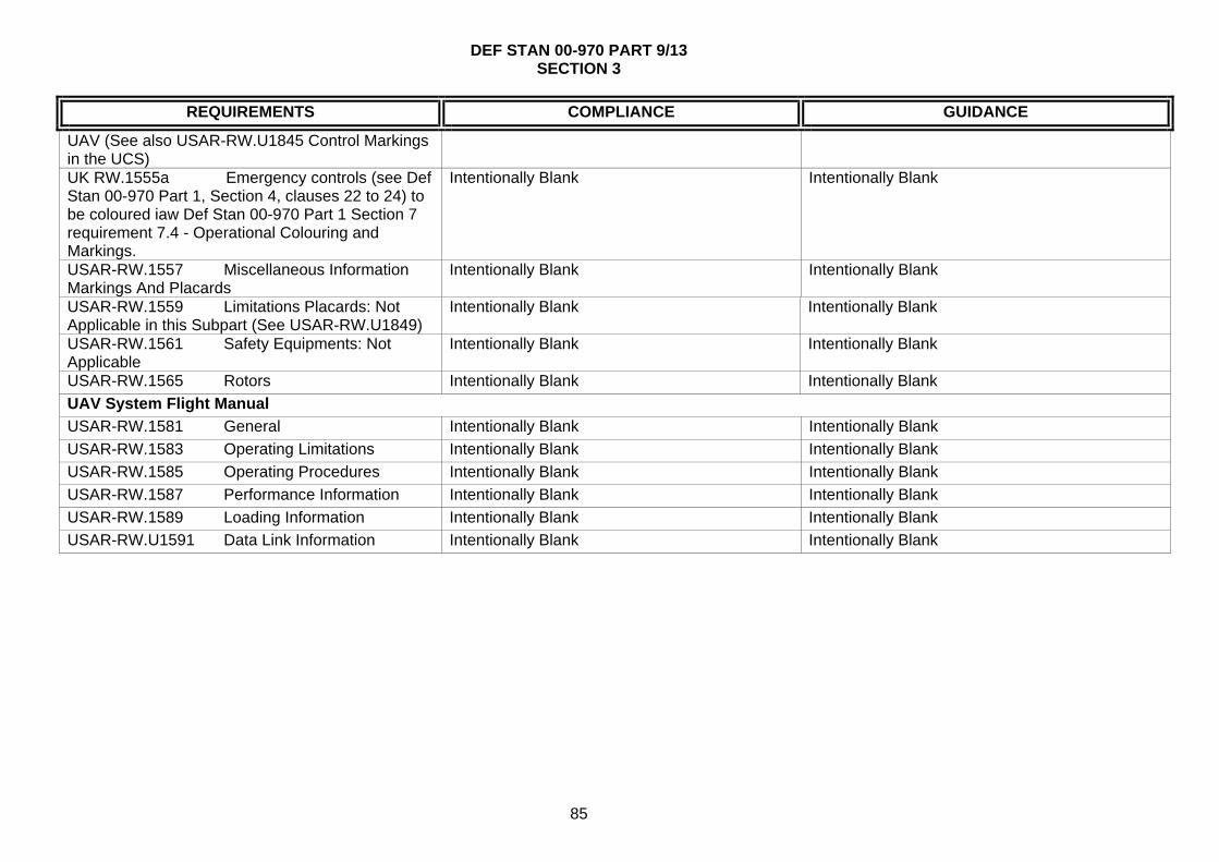
DEF STAN 00-970 PART 9/13 SECTION 3
85
REQUIREMENTS COMPLIANCE GUIDANCE
UAV (See also USAR-RW.U1845 Control Markings in the UCS) UK RW.1555a Emergency controls (see Def Stan 00-970 Part 1, Section 4, clauses 22 to 24) to be coloured iaw Def Stan 00-970 Part 1 Section 7 requirement 7.4 - Operational Colouring and Markings.
Intentionally Blank Intentionally Blank
USAR-RW.1557 Miscellaneous Information Markings And Placards
Intentionally Blank Intentionally Blank
USAR-RW.1559 Limitations Placards: Not Applicable in this Subpart (See USAR-RW.U1849)
Intentionally Blank Intentionally Blank
USAR-RW.1561 Safety Equipments: Not Applicable
Intentionally Blank Intentionally Blank
USAR-RW.1565 Rotors Intentionally Blank Intentionally Blank
UAV System Flight Manual
USAR-RW.1581 General Intentionally Blank Intentionally Blank
USAR-RW.1583 Operating Limitations Intentionally Blank Intentionally Blank
USAR-RW.1585 Operating Procedures Intentionally Blank Intentionally Blank
USAR-RW.1587 Performance Information Intentionally Blank Intentionally Blank
USAR-RW.1589 Loading Information Intentionally Blank Intentionally Blank
USAR-RW.U1591 Data Link Information Intentionally Blank Intentionally Blank

DEF STAN 00-970 PART 9/13 SECTION 3
86
REQUIREMENTS COMPLIANCE GUIDANCE
Subpart H - Command and Control Data Link
USAR-RW.U1601 General USAR-RW.AMC.1601 Intentionally Blank
UK RW.U1601a Communication - Link Capacity - The link capacity shall be such that, on entry into service, there is a spare capacity of at least 30%.
Link budgets that identify the data to be carried on each link (analogue/digital) shall be defined, with parameters such as data rates, update rates, bandwidths and signal levels being addressed. A link capacity report shall be published to the MOD (PTL) early in the project and maintained through the life of the project.
Intentionally Blank
UK RW.U1601b Links to the launcher and launch personnel shall be established such that launch is inhibited until the RPAV-pilot/RPAV Commander is satisfied that all pre-flight checks have been completed and is ready to initiate the launch sequence.
Failure Modes Effects and Criticality Analysis (FMECA) shall be carried out to consider all failure modes and their effects on launch procedures. Hazards associated with each failure shall be recorded in the RPAS Hazard Log and addressed in the RPAS Hazard Analysis. Appropriate mitigations shall be taken to reduce these hazards to acceptable levels.
Reference should be made to Def Stan 00-56.
USAR-RW.U1603 Command And Data Link Architecture
USAR-RW.AMC.1603 Intentionally Blank
UK RW.U1603a Guidance and Control - Safety consideration - Provision shall be made for the avoidance of Controlled Flight Into Terrain (CFIT)
The chosen effective method of providing CFIT avoidance shall be agreed with the MOD (PTL) during the Demonstration Phase.
Both the provision of a radar altimeter and a digital terrain data base should be considered.
USAR-RW.U1605 Electromagnetic Interference And Compatibility
USAR-RW AMC.1605 and USAR-RW.AMC.1605(b)
Intentionally Blank
USAR-RW.U1607 Command And Control Data Link Performance And Monitoring
USAR-RW.AMC.1607(a) Intentionally Blank
UK RW.1607a Refer to UK National Reservations in part 1 - 1.2.2.d.(4)
Intentionally Blank Intentionally Blank
USAR-RW.U1611 Command And Control Data Link Latency
USAR-RW.AMC.1611(a) Intentionally Blank
USAR-RW.U1613 Command And Control Data Link Loss Strategy
USAR-RW.AMC.1613(a), (b) and (c) Intentionally Blank

DEF STAN 00-970 PART 9/13 SECTION 3
87
REQUIREMENTS COMPLIANCE GUIDANCE
USAR-RW.U1615 Command And Control Data Link Antenna Maskings
USAR-RW.AMC.1615 Intentionally Blank
UK RW.U1615a Covert Operation - The antenna installation shall meet requirements for covert operation.
Intentionally Blank Intentionally Blank
USAR-RW.U1617 Command And Control Data Link Switchover Function
USAR AMC.1617(a), (b) and (c) Intentionally Blank

DEF STAN 00-970 PART 9/13 SECTION 3
88
REQUIREMENTS COMPLIANCE GUIDANCE
Subpart I - UAV Control Station
General
USAR-RW.U1701 General USAR-RW.AMC.1701 and USAR-RW.AMC.1701(e)
Intentionally Blank
UK RW.U1701a Portable equipment for use in the field shall comply with the requirements of Def Stan 00-35 Environmental Handbook for Defence Materiel.
Portable equipment shall be designed to withstand the environment that it will experience when stowed in its parent facility, and the additional conditions to which it may be subjected when in use outside the facility - See AECTP 100-500 series Environmental Guidelines For Defence Materiel.
Intentionally Blank
UK RW.U1701b The design of the RPAS Support Facilities shall be consistent with the transportation requirements stated in the RPAS Requirements Specification.
Unless otherwise stated in the RPAS Requirements Specification, the requirements of Def Stan 00-3 shall apply.
Intentionally Blank
UK RW.U1701c The safety of the RPAS Support Facilities shall be consistent with achieving the overall safety of the complete RPAS.
The RPAS Support Facilities shall be designed in accordance with Health and Safety legislation and the safety management procedures of Def Stan 00-56. The RPAS Design Organisation shall produce a Safety Programme Plan. As part of the RPAS Safety Case, hazards associated with the RPAS Support Facilities will be identified in the RPAS Hazard log and addressed in the RPAS Hazard Analysis.
Intentionally Blank

DEF STAN 00-970 PART 9/13 SECTION 3
89
REQUIREMENTS COMPLIANCE GUIDANCE
UK RW.U1701d RPAS Support Facilities shall be fire proof wherever possible and comply with the applicable fire regulations.
Where complete fireproofing is not practicable the materials used in the design shall be selected to provide the greatest degree of fire resistance possible and to minimise the emission of toxic fumes.
BSI BS 476(Fire tests on building materials and structures), BS 5266 (Emergency Lighting), BS5499 (Fire Signs), BS5852 (Assessment of upholstered seating) AFNOR NF EN3 (Portable fire extinguishers), Fire Prevention on Construction Sites (published by the British Employers Confederation, the Loss Prevention Council and the National Contractors Group) and CS-Definitions, contain information which may be of assistance when determining the construction and location of RPAS Support Facilities elements. Note should be taken of any special requirements for airborne or shipborne installations.
UK RW.U1701e All emissions from the RPAS Support Facilities (such as RF, Infra Red, Visible, Ultra Violet, Audio, Laser) shall be controlled to meet the system detectability requirements.
Where possible, sources of radiated energy shall be sited remotely from the main control station. The compatibility of the Support facility with emission requirements shall be determined by analysis or demonstrated by test and trial to ensure that there is no interference with other aspects of the system's operation, it does not interfere with other systems or equipment in the vicinity, it does not present itself as a large target to attacking forces nor shall it cause harm or injury to operating personnel.
Intentionally Blank
UK RW.U1701f RPAS Support Facilities shall comply with the requirements of NBC compatibility called for in the RPAS Requirements Specification.
Unless otherwise detailed in the RPAS Requirements Specification, the RPAS Design Organisation shall make reference to Def Stan 08-4 (for nuclear environments), and Def Stan 08-41 Parts 1 and 2 for chemical environments. The MOD (PTL) shall stipulate whether all or which parts of the above documents are mandatory.
If further information is required, the MOD (PTL) should be approached for guidance on the conditions to be considered in the RPAS Requirements Specification.
USAR-RW.U1702 UCV Control Station Infrastructure
Intentionally Blank Intentionally Blank

DEF STAN 00-970 PART 9/13 SECTION 3
90
REQUIREMENTS COMPLIANCE GUIDANCE
UK RW.U1702a The stowage of hazardous systems such as fuel, rocket motors, pyrotechnics and other inflammable and explosive substances shall be in accordance with JSP 482.
Intentionally Blank JSP 482 also gives associated publications that could be relevant and should be referenced in the RPAS Requirement Specification as applicable.
USAR-RW.U1703 Rotorcraft UAV Crew Workplace
Intentionally Blank Intentionally Blank
UK RW.U1703a Workload analyses, using an agreed standard tool, shall be conducted during the Demonstration Phase.
The extent of the Workload Analyses shall be agreed with the MOD (PTL) As a minimum, these analyses shall measure the workload requirements placed on the RPAV - pilot(s) and RPAV Commander and identify whether or not it is possible for the RPAV-pilot(s) and RPAV Commander to safely control the RPAV in all phases of launch, flight and recovery without exceptional piloting skill, alertness, or strength and without danger of exceeding the aeroplane load-limit factor under any probable operating conditions.
Both safety and mission success criteria demand that the RPAV-pilot and RPAV Commander accommodation is comfortable in terms of the required mission or shift times. Equally important is an RPAS Crew to system interface which is natural and intuitive, particularly in periods of heightened stress.
UK RW.U1703b The design of the environmental and NBC conditioning of RPAS Crew compartments shall consider the needs of the operational personnel to ensure the maximization of efficiency and safety.
The conditions called up in Def Stan 00-35, Health and Safety Legislation shall be considered.
When necessary, the use of techniques such as over-pressurisation should be considered in order to meet the requirements of NBC control. This, in turn, will require that all equipment’s within a pressurised zone, including any hermetically sealed units, are capable of operating to their full specifications in their installed conditions. Escape hatches should be outward opening, prominent and have visual indication of their method of operation. They should not be positioned where they may be blocked or partially obscured by equipment inside or outside the Control Station.
USAR-RW.U1704 Minimum Rotorcraft UAV Crew
USAR-RW.AMC.1704 Intentionally Blank
USAR-RW.U1705 Rotorcraft UAV Crew Workplace Lights
Intentionally Blank Intentionally Blank

DEF STAN 00-970 PART 9/13 SECTION 3
91
REQUIREMENTS COMPLIANCE GUIDANCE
USAR-RW.U1707 Communication System USAR-RW.AMC.1707(a) and (c) Intentionally Blank
UK RW.U1707a Antenna Systems - Detection of the Emitter/Receiver by opposing forces shall be minimised.
Antenna systems shall be of minimum size and power and maximum directionality consistent with meeting the performance requirements in the RPAS Requirements Specification.
Consideration should be given to the remote siting of antennae systems, in order to minimise danger to personnel in the event of attacking forces using the associated radiated energy for targeting or terminal guidance of offensive munitions.
USAR-RW.U1709 Voice Recorders USAR-RW.AMC.1709 and USAR-RW.AMC.1709(e)
Intentionally Blank
USAR-RW.U1711 UAV Control Station Data Recorder
USAR-RW.AMC.1711 and USAR-RW.AMC.1711(a)
Intentionally Blank
USAR-RW.U1717 UCS Electrical Systems Intentionally Blank Intentionally Blank
USAR-RW.U1719 UCS Power Supply Intentionally Blank Intentionally Blank
USAR-RW.U1720 Automated Mission Planning USAR-RW.AMC.1720 Intentionally Blank
DATA Displayed in the UAV Control Station
USAR-RW.U1721 Arrangement & Visibility USAR-RW.AMC.1721 Intentionally Blank
UK RW.U1721a Controls and displays shall be developed with User participation.
Intentionally Blank Intentionally Blank
UK RW.U1721b Where conventional flying controls and displays are employed the form and layout shall be consistent with those of manned aircraft.
Reference shall be made to Def Stan 00-970 Part 1 Section 4, Clause 4.10.
Intentionally Blank
USAR-RW.U1722 Part-Time Data Display USAR-RW.AMC.1722 Intentionally Blank
USAR-RW.U1723 Flight And Navigation Data Intentionally Blank Intentionally Blank
USAR-RW.U1725 Powerplant Data USAR-RW.AMC.1725(t) and (u) Intentionally Blank
USAR-RW.U1727 Electronic Data Display USAR-RW.AMC.1727 and USAR-RW.AMC.1727(b)
Intentionally Blank
USAR-RW.U1728 Data Link Display, Warnings And Indicators
Intentionally Blank Intentionally Blank
USAR-RW.U1729 Fuel Quantity And Oil Quantity Data
Intentionally Blank Intentionally Blank
USAR-RW.U1730 Automatic Take-Off and Intentionally Blank Intentionally Blank

DEF STAN 00-970 PART 9/13 SECTION 3
92
REQUIREMENTS COMPLIANCE GUIDANCE
Landing Data
Controls
USAR-RW.U1731 General USAR-RW.AMC.1731 Intentionally Blank
USAR-RW.U1732 Safety Critical Controls Intentionally Blank Intentionally Blank
USAR-RW.U1733 Conventional Controls And Indicators
Intentionally Blank Intentionally Blank
USAR-RW.U1735 Motion And Representation Of Controls
Intentionally Blank Intentionally Blank
USAR-RW.U1738 Master Switch Arrangement Intentionally Blank Intentionally Blank
USAR-RW.U1741 Flight Controls Intentionally Blank Intentionally Blank
USAR-RW.U1742 Flight Termination System Control
Intentionally Blank Intentionally Blank
USAR-RW.U1743 Fuel Controls Intentionally Blank Intentionally Blank
USAR-RW.U1745 Fuel Jettisoning Control Intentionally Blank Intentionally Blank
USAR-RW.U1747 Air Induction Control Intentionally Blank Intentionally Blank
USAR-RW.U1748 Landing and Position Lights Control
Intentionally Blank Intentionally Blank
USAR-RW.U1749 External Load Control Intentionally Blank Intentionally Blank
USAR-RW.U1750 Rotor Brake Control Intentionally Blank Intentionally Blank
USAR-RW.U1751 Engine And APU Controls Intentionally Blank Intentionally Blank
USAR-RW.U1753 Ignition Switches USAR-RW.AMC.1753(b) Intentionally Blank
USAR-RW.U1755 Mixture Controls Intentionally Blank Intentionally Blank
USAR-RW.U1765 Shut-Off Controls Intentionally Blank Intentionally Blank
USAR-RW.U1769 Automatic Take-Off and Landing “Abort” Control
USAR-RW.AMC.1769 Intentionally Blank
Indicators and Warnings
USAR-RW U1785 Warning, Caution And Advisory Information Colour Code
Intentionally Blank Intentionally Blank
USAR-RW.U1787 Rotorcraft UAV Automatic Diagnostic And Monitoring
USAR-RW.AMC.1787(a) Intentionally Blank
UK RW.U1787a Health monitoring data shall Intentionally Blank Intentionally Blank

DEF STAN 00-970 PART 9/13 SECTION 3
93
REQUIREMENTS COMPLIANCE GUIDANCE
be available to be electronically entered into the DRACAS (Def Stan 00-40) database. USAR-RW.U1788 Degraded Modes Of Operation Warning
Intentionally Blank Intentionally Blank
USAR-RW.U1790 UAV Mode Of Control Indicator
Intentionally Blank Intentionally Blank
USAR-RW.U1793 Landing Gear Position Indicator And Warning
Intentionally Blank Intentionally Blank
USAR-RW.U1794 Chip Detectors Intentionally Blank Intentionally Blank
USAR-RW.U1795 ECS and Pressurised Compartment Indicators
USAR-RW.AMC.1795 Intentionally Blank
USAR-RW.U1797 Fuel Pumps Warning Intentionally Blank Intentionally Blank
USAR-RW.U1798 Low Fuel Warning Intentionally Blank Intentionally Blank
USAR-RW.U1799 Air Induction Indicator Intentionally Blank Intentionally Blank
USAR-RW.U1803 Indicators For Power-Assisted Valves In The Powerplant
USAR-RW.AMC.1803 Intentionally Blank
USAR-RW.U1805 Shut Off Valves Indicator Intentionally Blank Intentionally Blank
USAR-RW.U1807 Oil Filter Intentionally Blank Intentionally Blank
USAR-RW.U1809 Rotorcraft UAV Electrical Systems Warning And Indicator
USAR-RW.AMC.1809 Intentionally Blank
USAR-RW.U1813 Hydraulic Systems Indicator Intentionally Blank Intentionally Blank
USAR-RW.U1817 Fire Protection Warning Intentionally Blank Intentionally Blank
USAR-RW.U1819 Pitot Heat Indicator Intentionally Blank Intentionally Blank
USAR-RW.U1821 Power Distribution Indicator USAR-RW.AMC.1821 Intentionally Blank
USAR-RW.U1825 Flight Controls Lock Warning Intentionally Blank Intentionally Blank
USAR-RW.U1827 Flight Path Deviation Warning
Intentionally Blank Intentionally Blank
USAR-RW.U1828 Main Rotor Low Speed Warning for helicopter UAVs
Intentionally Blank Intentionally Blank
USAR-RW.U1829 Safety Status Indication Intentionally Blank Intentionally Blank
USAR-RW.U1830 Rotor Brake Warning Intentionally Blank Intentionally Blank

DEF STAN 00-970 PART 9/13 SECTION 3
94
REQUIREMENTS COMPLIANCE GUIDANCE
Information, Markings and Placards
USAR-RW.U1831 General Intentionally Blank Intentionally Blank
USAR-RW.U1835 Airspeed Data Intentionally Blank Intentionally Blank
USAR-RW.U1837 Magnetic Heading Or Track Data
USAR-RW.AMC.1837 Intentionally Blank
USAR-RW.U1839 Powerplant And Auxiliary Power Unit Data
Intentionally Blank Intentionally Blank
USAR-RW.U1841 Oil Quantity Data Intentionally Blank Intentionally Blank
USAR-RW.U1843 Fuel Quantity Data Intentionally Blank Intentionally Blank
USAR-RW U1845 Control Markings USAR-RW.AMC.1845(e)(2) Intentionally Blank
UK RW.U1845a Emergency controls (see Def Stan 00-970 Part 1, Section 4, clauses 22 to 24) to be coloured iaw Def Stan 00-970 Part 1 Section 7 requirement 7.4 - OPERATIONAL COLOURING AND MARKINGS
Intentionally Blank Intentionally Blank
USAR-RW U1849 Operating Limitations Placard Intentionally Blank Intentionally Blank
USAR-RW U1851 Rotor Brake Intentionally Blank Intentionally Blank
Miscellaneous
USAR-RW.U1881 Rotorcraft UAV Hand Over Between Two UAV Control Stations
USAR-RW.AMC.1881(b), (c) and (d) Intentionally Blank
USAR-RW.U1883 Command And Control Of Multiple UAVs
Intentionally Blank Intentionally Blank
USAR-RW.U1885 UAV Handover Within The Same UAV Control Station
USAR-RW.AMC.1885(b) and (d) Intentionally Blank
USAR-RW.U1887 Multiple Rotorcraft UAV Monitoring
Intentionally Blank Intentionally Blank

DEF STAN 00-970 PART 9/13 SECTION 3
95
REQUIREMENTS COMPLIANCE GUIDANCE
Appendix A - Instructions for Continued Airworthiness
USAR Instructions For Continued Airworthiness
Intentionally Blank Intentionally Blank
Appendix B - Not Applicable
Appendix C – Icing Certification
USAR Icing Certification Intentionally Blank Intentionally Blank
Appendix D – HIRF Environments and Equipment HIRF Test Levels
USAR HIRF Environments and Equipment HIRF Test Levels
Intentionally Blank Intentionally Blank
Appendix E – Not Applicable
Appendix F - Test Procedure for Self-Extinguishing Materials
USAR Test Procedure For Self-Extinguishing Materials
Intentionally Blank Intentionally Blank

DEF STAN 00-970 PART 9/13 SECTION 4
96
SECTION 4 LIGHT FIXED WING - AIRWORTHINESS CODE AND ACCEPTABLE MEANS OF COMPLIANCE (AMC) (Sub 150 kg)
INTRODUCTION
AEP-83.1 Scope
AEP-83.2 Introduction
AEP-83.3 Type Design Airworthiness Evidence
UK LFW-83.3a Refer to UK National Reservations in part 1 - 1.2.2.e.(1)
AEP-83.4 Source Documents
AEP-83.5 Restricted Certification
AEP-83.6 Requirements

DEF STAN 00-970 PART 9/13 SECTION 4
97
AIRWORTHINESS ESSENTIAL REQUIREMENT
DETAILED ARGUMENTS MEANS OF EVIDENCE
UL.0 – Design Usage Spectrum
UK LFW.0a Transportation and storage requirements are detailed in STANAG 4671, Para U249, and shall be agreed between the DO and the PTL.
ME.0 ER.1 - System Integrity
UL.1 – Design Criteria ME.1
UL.2 – Design Load Margin
UL.2.1
UL.2.2
UL.2.3
ER.1.1 – Structures and Materials
UL.2.4
ME.2
UL.3 – Primary Structural Elements Identification ME.3 ER.1.1.1
UL.4 – PSE Criteria ME.4
UL.5 – Flight Loads
UL.5.1
UL.5.2
UL.5.3
UL.5.4
UL.5.5
UL.5.6
UL.6 – Ground Loads
ER.1.1.1.1
UL.6.1
ME.5

DEF STAN 00-970 PART 9/13 SECTION 4
98
AIRWORTHINESS ESSENTIAL REQUIREMENT
DETAILED ARGUMENTS MEANS OF EVIDENCE
UL.6.2
UK LFW.6.2a Landing Energy Absorber System - Any on-board Landing Energy Absorber System (LEAS) shall be such as to control the release of absorbed energy to avoid unnecessary damage to the RPAV. The LEAS shall ensure that the loads which would be transferred to the airframe and payloads on impact with the landing surface are consistent with the structural requirements stated in UL.6 and any limitations imposed by the payload. LEAS may include: conventional undercarriage or skids, airbags, retro-rockets, crushable or frangible components, braking parachutes, electromagnetic retardation devices, The system may include devices that are not part of the airframe such as; arrestor wires, nets, impact absorbing material and mid air recovery systems. UK LFW.6.2b The loads applied to the airframe during engagement shall be considered as part of the structural design and subject to the strength factors stated in UL.2 Where the LEAS is independent of the RPAV and is located on the landing surface or elsewhere, the airframe should be provided with the appropriate means of engagement and retrieval. Reference should be made to UL.58 Flight Envelope. UK LFW.6.2c The turn-round requirements of the LEAS shall be in accordance with the RPAV System Requirement Specification. This may involve recharging gas cylinders, re-packing parachutes, replacing blow-out patches in air-bags or resetting mechanical and electrical systems or the replacement of airframe mounted components.
UL.6.3
ER.1.1.1.2 Not Applicable Not Applicable
ER.1.1.1.3 UL.7 – Structural Dynamic Load response ME.7
ER.1.1.2 UL.8 – Aeroservoelastic Effects ME.8
UL.9 – Material Allowables ER.1.1.3
UK LFW.9a Where a RPAV is to be constructed in modular form, assembly and dismantling shall be simple and require the minimum of jigging and tooling. The airframe shall utilise substantiated structural technology. New methods shall be
ME.9

DEF STAN 00-970 PART 9/13 SECTION 4
99
AIRWORTHINESS ESSENTIAL REQUIREMENT
DETAILED ARGUMENTS MEANS OF EVIDENCE
substantiated as part of the qualification test programme and approved by the MOD (PTL). UL.9.1
UL.9.2
UL.9.3
UL.10 – Quality Assurance ME.10
UL.11 - Fatigue
UL.11.1
UL.11.2
UL.11.2.1
UL.11.2.2
UL.11.2.3
ME.11
UL.12 – Structural Protection (Environmental)
UK LFW.12a External colouring and markings of the RPAV shall be in accordance with DAP119A-0601-Series unless otherwise specified in the contract. The decision to use specific colours shall be agreed by the MOD (PTL). Where a RPAV is of modular construction the nationality and registration mark shall be applied to the fuselage of the vehicle or on the assembly forming the main part of the fuselage.
ER.1.1.4
UK LFW.12b Air vehicles being regulated under the MAP RA1100 series shall be given a nationality, registration and combatant marking. For other air vehicles a combatant marking only shall be required. To prevent the high usage of registration numbers for target drones, which are eventually destroyed, the recommendation is that a single registration mark (prefix) should be issued by the MAR relating to RPAV type. The Agency or Service operating the equipment will be responsible for the identification of each individual RPAV covered by that registration mark by adding a suffix.
ME.12

DEF STAN 00-970 PART 9/13 SECTION 4
100
AIRWORTHINESS ESSENTIAL REQUIREMENT
DETAILED ARGUMENTS MEANS OF EVIDENCE
UL.13 - Structural Protection (Accidental and Discrete Damage sources)
UL.13.1
UL.13.1.1
UL.13.1.2
UL.13.2
ME.13
UL.14 – Maintenance Accessibility
UK LFW.14a Fasteners shall be capable of easy operation by personnel wearing the clothing and working in the environmental conditions stated in the RPAS Requirement Specification. UK LFW.14b Fasteners shall be proofed against incorrect closure.
UK LFW.14c Access hatches shall be large enough to allow adequate access to installed equipment for maintenance and service by personnel wearing the protective clothing (NBC, cold weather, etc.) specified in the RPAS Requirements Specification. Parts that require regular inspection for replacement shall be readily accessible and care shall be taken to ensure that no sharp edges or corners are exposed where access is required for servicing and/or maintenance.
ME.14
UL.15 – Promulgation of Continued Airworthiness Instructions ME.15

DEF STAN 00-970 PART 9/13 SECTION 4
101
AIRWORTHINESS ESSENTIAL REQUIREMENT
DETAILED ARGUMENTS MEANS OF EVIDENCE
UL.16 – Engine
UK LFW.16a Where the projected life span of the RPAV dictates, a fatigue analysis shall be applied to the relevant components in the transmission system. UK LFW.16b For RPAVs employing extended drive shafts, means shall be provided to ensure that no dangerous torsional or flexural vibration or whirling can occur throughout the torque and RPM range. UL.16.1
UL.16.2
UL.16.3
ME.16
UL.17 - Propeller
UK LFW.17a The design of the propeller shall be consistent with the acoustic, thermal, radar and visual signatures as specified in the RPAS Requirement Specification.
ER.1.2 - Propulsion
UK LFW.17b Positive indication that propeller blades are correctly and securely fitted shall be provided.
ME.17
UL.18 – Propulsion System Compatibility
UK LFW.18a For RPAVs utilising turbine / piston engines and rocket motor installations a power plant specification shall be produced based upon the appropriate standards that apply to manned aircraft power plants (in particular Def Stan 00-970 Part 1 Section 5) and associated sub-systems. UK LFW.18b For RPAVs that utilise other methods of propulsion, a power plant specification that provides levels of design integrity and safety consistent with Def Stan 00-970 Part 11 and Part 1 Section 5 shall be produced. UK LFW.18c The power plant specification developed to comply with UK 18a or UK 18b shall adequately address any potential hazards or failures modes that could result from operational requirements over and above those for manned aircraft. For example, RPAV power plants may be required to operate under significantly higher G loading than those for manned aircraft.
ER.1.2.1
UK LFW.18d The power plant shall be of such a design that it enables the RPAV to comply with operational, reliability, maintainability, environmental and safety requirements defined in the RPAS Requirements Specification.
ME.18

DEF STAN 00-970 PART 9/13 SECTION 4
102
AIRWORTHINESS ESSENTIAL REQUIREMENT
DETAILED ARGUMENTS MEANS OF EVIDENCE
The power plant is defined as the integrated assemblage of components and subsystems that provides; the power in the appropriate form for flight propulsion, lift (VTOL) and auxiliary systems such as electrical power generation. The engine is defined to be the core component that provides motive power and can be of the following configurations gas turbine, reciprocating internal combustion, reciprocating compressed gas, rotary internal combustion ramjet, pulsejet or electric motors. The power plant should have the potential to deliver additional power to maintain the specified performance should the RPAV mass increase and where possible, the engine/power module should be a single change unit requiring the minimum number of disconnections. The disturbance to other elements of the propulsion or other systems should also be minimised. UK LFW.18e The use of special tools shall be kept to a minimum. Any specialist tools to be used shall be agreed by the MOD (PTL) UK LFW.18f The integration of the power plant into the airframe shall be consistent with the acoustic, aerodynamic, radar and thermal signatures of the RPAV. UK LFW.18g Systems utilising solid and liquid rocket fuels shall be in accordance with Def Stan 07-85. UK LFW.18h Engine Starting Systems - For safety reasons, hand-held engine starters shall only be employed when the small size of a RPAV precludes a fixed alternative. The engine starting system may be separate and independent from the RPAV as such consideration should be given to ensure the safety of launch personnel throughout all stages of engine power-up, to the inclusion of guards on the engine starting device and to the provision of a suitable means of stabilisation or support for both the hand-held engine starter and the RPAV. UK LFW.18i All controls for hand-held engine starting devices shall be accessible only to the person starting the engine. UK LFW.18j Engine starting devices shall employ safety features such as momentary main switches and over-run clutches.
UK LFW.18k For turbine engines, reference shall be made to Def Stan 00-970 Part 1 Sections 5 and 8, Part 11 and CS-E. Compliance shall be demonstrated against relevant sections within of Def Stan 00-970 Part 1 Sections 5 and 8, and Part 11 and agreed with the MOD (PTL).

DEF STAN 00-970 PART 9/13 SECTION 4
103
AIRWORTHINESS ESSENTIAL REQUIREMENT
DETAILED ARGUMENTS MEANS OF EVIDENCE
UK LFW.18l For piston engines, reference shall be made to CS-E and to FAR 33. Compliance shall be demonstrated against the engine specification requirements within CS-E and agreed with the MOD (PTL) UK LFW.18m For rocket motors, reference shall be made to the requirements set out in Def Stan 07-85. Compliance shall be demonstrated against the engine specification sections within Def Stan 07-85 and agreed with the MOD (PTL) UK LFW.18n Engine environmental impact shall be minimised. The design shall be carried out in accordance with ISO 14001 principles. UK LFW.18o The engine shall be mounted in the RPAV in such a manner as to keep transmitted vibration outside frequencies and amplitudes that would have deleterious effects on the integrity and performance of the RPAV structures, mechanisms, avionics and payload or harmful effects to personnel (for example during hand held launch) or the general public. The RPAV Design Organisation and the RPAV Power plant Design Organisation shall agree vibration limits caused by the interaction of the power plant and the RPAV in all configurations such that the performance or safety requirements of the RPAV stated in the RPAS Requirement Specification are not unacceptably compromised. UK LFW.18p The use of novel engine design or configurations shall be approved by the MOD (PTL) Novel engine designs shall meet the requirements of Def Stan 00-970 Part 11 and Part 1 Section 5. It should be noted that novel engine configurations will be subjected to the certification processes as defined in Def Stan 00-970 part 11 and Map RA 5000 series. UK LFW.18q Sufficient power shall be available to cover the maximum load conditions of the RPAS. A power requirement calculation shall be performed. Consideration should be given to the inclusion of a tolerance for potential future development. The power requirement calculation should take into account electrical, mechanical, pneumatic or hydraulic subsystems and possible payloads.
UK LFW.18r Power Loading - Operational degradation due to partial loss of

DEF STAN 00-970 PART 9/13 SECTION 4
104
AIRWORTHINESS ESSENTIAL REQUIREMENT
DETAILED ARGUMENTS MEANS OF EVIDENCE
power shall be managed. Critical systems shall be identified and priority given to maintaining their integrity. The critical systems may be considered to be the RPAV flight control and safety systems and Consideration should be given to selective load shedding for operational contingencies. UL.18.1
UL.18.2
UL.18.3
UL.18.4
UL.18.5 – Air Inlet
UK LFW.18.5a The location of any cooling air apertures, ducts or radiators shall be consistent with the requirements for acoustic, radar, thermal and visual signatures. UK LFW.18.5b The installation of the induction system shall ensure that adequate protection is provided for personnel. Hazard and warning signs shall be displayed on the appropriate surfaces and locations of the RPAV. Consideration should be given to the use of ground running guards. UK LFW.18.5c The induction system shall be consistent with the requirements for RPAV acoustic, radar, thermal and visual signatures. UL.18.5.1
UL.18.5.2
UL.18.6 – Exhaust System
UK LFW.18.6a The exhaust and jet efflux system shall meet the requirements for RPAV acoustic, radar, thermal and visual signatures.
UL.18.7 – Electrical System
ER.1.2.2 This Essential Requirement is met by compliance with UL.16 and UL.17.
ER.1.2.3 This Essential Requirement is met by compliance with UL.16 and UL.17.
ER.1.2.4 This Essential Requirement is met by compliance with UL.16 and UL.17.
UL.19 – Fuel System for Spark and Compression Ignition Engines ER.1.2.5 UK LFW.19a Refer to UK National Reservations in part 1 - 1.2.2.e.(2)
ME.19

DEF STAN 00-970 PART 9/13 SECTION 4
105
AIRWORTHINESS ESSENTIAL REQUIREMENT
DETAILED ARGUMENTS MEANS OF EVIDENCE
UK LFW.19b For Fuel System Lightning Protection - See Def Stan 59-113
UL.19.1
UL.19.2
UL.19.3
UL.19.4
UL.19.5
UL.19.6
UL.19.7
UL.19.8
UL.19.9
UL.20 – Electric Power Subsystem
UK LFW.20a Other fuels and Energy Sources - Where unconventional energy sources are utilised, they shall not hazard personnel or adversely affect the air vehicle. Where unconventional energy sources are proposed they shall be agreed by the MOD (PTL) Unconventional energy sources currently include the use of solar energy, microwave energy and regeneration systems. It should be noted that such systems might, in due course, be considered conventional. UK LFW.20b The RPAS shall comply with the requirements of Def Stan 59-411- Electromagnetic Compatibility, for EMC and ECM, and Def Stan 59-113 for Lightening protection. The control plan, requirements, trials and Tests shall be agreed by the MOD (PTL). The achievement of EMC in a RPAS is a relatively complex matter because of the different nature of the requirement for the Air Vehicle, Ground Control Elements and the Communication/Data Links between the two and to the “outside world” in respect of a relatively “small” RPAS. The differing requirements for Sea, Air and Land systems should be taken into account. DE3A (Contact details in Def Stan 59-411) should be consulted, being able to offer E3 Functional Assurance at all stages of a project. UL.20.1
ME.20

DEF STAN 00-970 PART 9/13 SECTION 4
106
AIRWORTHINESS ESSENTIAL REQUIREMENT
DETAILED ARGUMENTS MEANS OF EVIDENCE
UL.20.2
UL.20.3
UL.20.4
UL.20.5
UL.20.6
UL.20.7
UL.20.8
UL.20.9

DEF STAN 00-970 PART 9/13 SECTION 4
107
AIRWORTHINESS ESSENTIAL REQUIREMENT
DETAILED ARGUMENTS MEANS OF EVIDENCE
ER.1.3 – Systems and Equipment
UL.21 – Design Criteria Substantiation UK LFW.21a For Electrical Bonding And Protection Against Lightning And Static Electricity - See Def Stan 59-113 UK LFW.21b Mounting and Protection of Components - Components shall be mounted and protected to established standards. Components shall comply with the requirements of BS EN 60194 Printed Board Design, Manufacture and Assembly, IPC 2221B, Printed Wiring for Electronic Equipment or similar approved design standard agreed with the MOD (PTL). Subject to the operating conditions of components, conformal coating in accordance with the requirements of BS EN-61086-3-1 shall be used to protect circuit boards except where hermetically sealed enclosures are used. Where identification of individual components is made in printed circuit or mounting boards, the identification where practicable shall be visible. Where practicable, the polarity markings of polarized components shall be placed adjacent to them. UK LFW.21c Static Charge - Equipment that is sensitive to static charge shall be marked accordingly. Where the design requires Electro Static Sensitive Devices (ESSD) are fitted, precautions shall be taken to minimize the risk of damage to such devices during operation and maintenance. The design of the equipment shall take into account the need to minimize the risk of damage. UK LFW.21d Programmable Memory Devices - The design of modules shall allow for the re-programming of memory devices. The application of memory devices shall be designed so that, whenever possible, they may be re-programmed on the parent module. Where this is not practicable, the devices shall be easily removable for re-programming. UK LFW.21e Electrical Systems and Wiring - The requirements of Def Stan 00-970 Part 1 Section 6 Leaflets 4, 14, 15, 16, and 35 shall be considered. UK LFW.21f Electrical Systems and Wiring - The installation shall be designed for ease of maintenance.
ER.1.3.1
UK LFW.21g If the air vehicle carries a payload that is designed to be jettisoned or released on command, the electrical installation of the arming and release system shall conform to Def Stan 00-970 Part 13 Sections 3.1 (Armament
ME.21

DEF STAN 00-970 PART 9/13 SECTION 4
108
AIRWORTHINESS ESSENTIAL REQUIREMENT
DETAILED ARGUMENTS MEANS OF EVIDENCE
Installations – General), 3.2 (Armament Control System) and 3.14 (Integration of Stores) UL LFW.21h Electrical Interfaces - Established standards such as RS 422, MIL STD 1760 and MIL STD 1553B shall be used wherever practicable.
UL.22 – Safety Tracking System ME.22
UL.23 – Flight Test ME.23
UL.24 - Equipment UK LFW.24a Refer to UK National Reservations in part 1 - 1.2.2.e.(3) UK LFW.24b Refer to UK National Reservations in part 1 - 1.2.2.e.(4) UK LFW.24c The RPAS shall comply with the requirements of Def Stan 00-40 Reliability and Maintainability (R & M). The equipment R & M programme shall be conducted in accordance with the series of Defence Standards in the Def Stan 00-40 to 00-44 range, as agreed between the RPAS Design Organisation and the MOD (PTL). The terms applicable to this clause are defined in Allied Reliability and Maintainability Publication (ARMP) 7 and Def Stan 00-49. Within this Defence Standard, the term R & M is used as a standard top level abbreviation, and embraces all of the following terms: reliability, maintainability, testability, durability and availability. Guidance on the achievement of testability requirements can be gained from Def Stan 00-42 Part 4. Pre-flight test requirements should be derived from reliability and mission success requirements. UK LFW.24d As far as practicable, fuels, oils and lubricants employed in the launch and recovery systems shall be selected from Def Stan 01-5. The Design Organisation shall identify any fuels, oils or lubricants needed which are not covered in Def Stan 01-5. The agreement of the MOD (PTL) shall be obtained before fuels, oils or lubricants not in Def Stan 01-5 are used.
ER.1.3.2
UK LFW.24e Installation of Explosive Devices - All explosive devices to be fitted to the RPAV shall be approved by the relevant MOD authorities, shall be installed so as to be easily accessible and shall not require excessive handling during installation. Protective sheaths or grommets shall be used where there is the likelihood of damage being caused by handling or vibration. Electrical circuits associated with the installation of explosive devices shall conform to Def Stan 00-970 Part 1, Section 6 Clause 6.6
ME.24
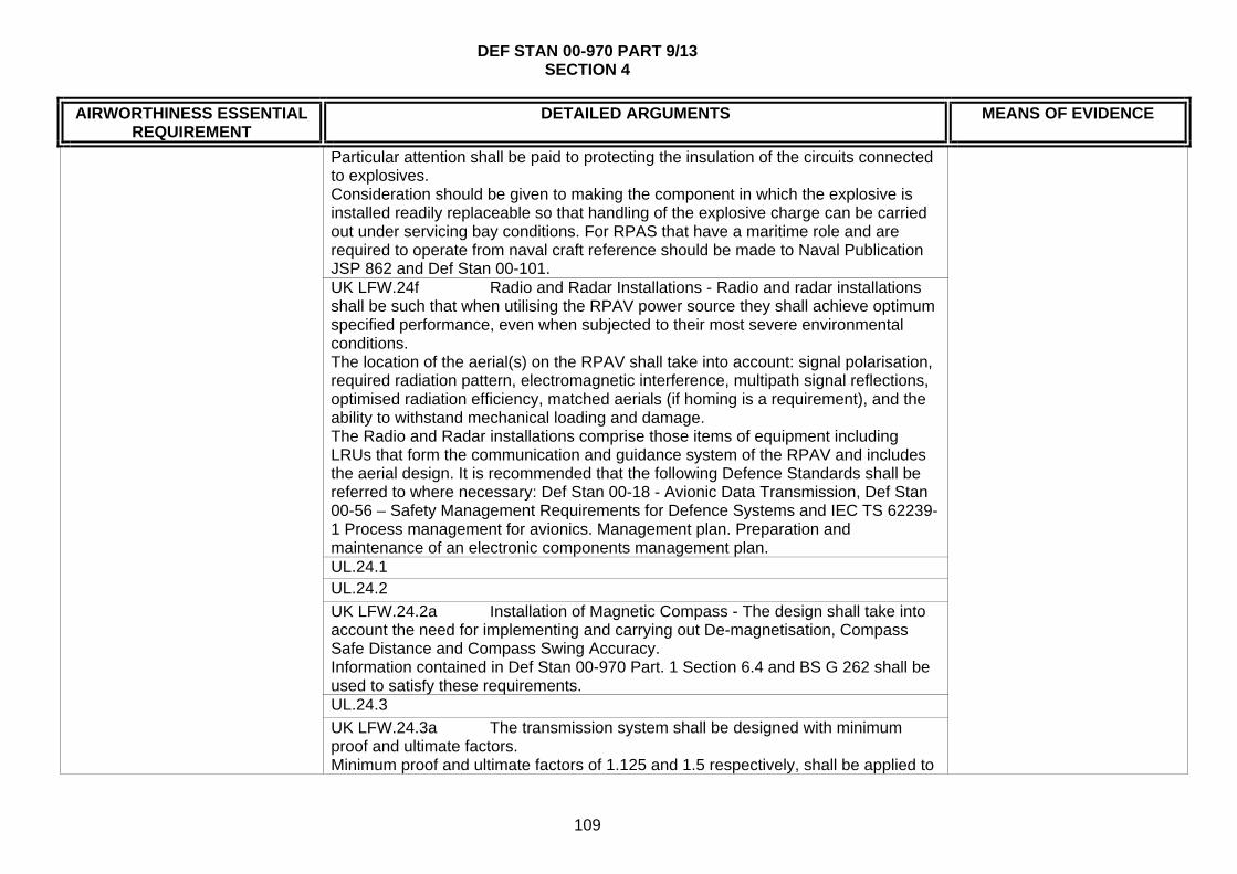
DEF STAN 00-970 PART 9/13 SECTION 4
109
AIRWORTHINESS ESSENTIAL REQUIREMENT
DETAILED ARGUMENTS MEANS OF EVIDENCE
Particular attention shall be paid to protecting the insulation of the circuits connected to explosives. Consideration should be given to making the component in which the explosive is installed readily replaceable so that handling of the explosive charge can be carried out under servicing bay conditions. For RPAS that have a maritime role and are required to operate from naval craft reference should be made to Naval Publication JSP 862 and Def Stan 00-101. UK LFW.24f Radio and Radar Installations - Radio and radar installations shall be such that when utilising the RPAV power source they shall achieve optimum specified performance, even when subjected to their most severe environmental conditions. The location of the aerial(s) on the RPAV shall take into account: signal polarisation, required radiation pattern, electromagnetic interference, multipath signal reflections, optimised radiation efficiency, matched aerials (if homing is a requirement), and the ability to withstand mechanical loading and damage. The Radio and Radar installations comprise those items of equipment including LRUs that form the communication and guidance system of the RPAV and includes the aerial design. It is recommended that the following Defence Standards shall be referred to where necessary: Def Stan 00-18 - Avionic Data Transmission, Def Stan 00-56 – Safety Management Requirements for Defence Systems and IEC TS 62239-1 Process management for avionics. Management plan. Preparation and maintenance of an electronic components management plan. UL.24.1 UL.24.2
UK LFW.24.2a Installation of Magnetic Compass - The design shall take into account the need for implementing and carrying out De-magnetisation, Compass Safe Distance and Compass Swing Accuracy. Information contained in Def Stan 00-970 Part. 1 Section 6.4 and BS G 262 shall be used to satisfy these requirements. UL.24.3
UK LFW.24.3a The transmission system shall be designed with minimum proof and ultimate factors. Minimum proof and ultimate factors of 1.125 and 1.5 respectively, shall be applied to

DEF STAN 00-970 PART 9/13 SECTION 4
110
AIRWORTHINESS ESSENTIAL REQUIREMENT
DETAILED ARGUMENTS MEANS OF EVIDENCE
the transmitted loads over the full range of operation conditions unless otherwise stated in the RPAS Requirement Specification. Reference should be made to Def Stan 00-970 Part 1 Section 3.1 (Static Strength) and Section 3.2 (Fatigue). The MOD (PTL) may agree to a relaxation of this requirement if the RPAS Design Organisation can show that safety and airworthiness will not be degraded. UL.24.4
UL.24.5
UL.24.6 UL.25 – Sub-System Function and Environmental Tests ME.25
UL.26 – Command and Control Data Link Subsystem UK LFW.26a Covert Operation - The antenna installation shall meet requirements for covert operation. UL.26.1 UK LFW.26.1a For RPAS equipped with Automatic Diagnostic and Monitoring Systems this DATA shall be available to be electronically entered into the DRACAS (Def Stan 00-40) database. UL.26.2 – Data Link Performance UK LFW.26.2a Communication - Link Capacity: The link capacity shall be such that, on entry into service, there is a spare capacity of at least 30%. Link budgets that identify the data to be carried on each link (analogue/digital) shall be defined, with parameters such as data rates, update rates, bandwidths and signal levels being addressed. A link capacity report shall be published to the MOD (PTL) early in the project and maintained through the life of the project. UL.26.3
UK LFW.26.3a Guidance and Control - Safety consideration: Provision shall be made for the avoidance of Controlled Flight Into Terrain (CFIT) The chosen effective method of providing CFIT avoidance shall be agreed with the MOD (PTL) during the Demonstration Phase. Both the provision of a radar altimeter and a digital terrain data base should be considered.
ME.26
UL.27 – UCS/UCB ME.27

DEF STAN 00-970 PART 9/13 SECTION 4
111
AIRWORTHINESS ESSENTIAL REQUIREMENT
DETAILED ARGUMENTS MEANS OF EVIDENCE
UK LFW.27a Portable equipment for use in the field shall comply with the requirements of Def Stan 00-35 Environmental Handbook for Defence Materiel. Portable equipment shall be designed to withstand the environment that it will experience when stowed in its parent facility, and the additional conditions to which it may be subjected when in use outside the facility - See AECTP 100-500 series Environmental Guidelines For Defence Materiel. UK LFW.27b The design of the RPAS Support Facilities shall be consistent with the transportation requirements stated in the RPAS Requirements Specification. Unless otherwise stated in the RPAS Requirements Specification, the requirements of Def Stan 00-3 shall apply. UK LFW.27c The safety of the RPAS Support Facilities shall be consistent with achieving the overall safety of the complete RPAS. The RPAS Support Facilities shall be designed in accordance with Health and Safety legislation and the safety management procedures of Def Stan 00-56. The RPAS Design Organisation shall produce a Safety Programme Plan. As part of the RPAS Safety Case, hazards associated with the RPAS Support Facilities will be identified in the RPAS Hazard log and addressed in the RPAS Hazard Analysis. UK LFW.27d RPAS Support Facilities shall be fire proof wherever possible and comply with the applicable fire regulations. Where complete fireproofing is not practicable the materials used in the design shall be selected to provide the greatest degree of fire resistance possible and to minimise the emission of toxic fumes. BSI BS 476(Fire tests on building materials and structures), BS 5266 (Emergency Lighting), BS5499 (Fire Signs), BS5852 (Assessment of upholstered seating) AFNOR NF EN3 (Portable fire extinguishers), Fire Prevention on Construction Sites (published by the British Employers Confederation, the Loss Prevention Council and the National Contractors Group) and CS-Definitions, contain information which may be of assistance when determining the construction and location of RPAS Support Facilities elements. Note should be taken of any special requirements for airborne or shipborne installations. UK LFW.27e All emissions from the RPAS Support Facilities (such as RF, Infra Red, Visible, Ultra Violet, Audio, Laser) shall be controlled to meet the system detectability requirements. Where possible, sources of radiated energy shall be sited remotely from the main
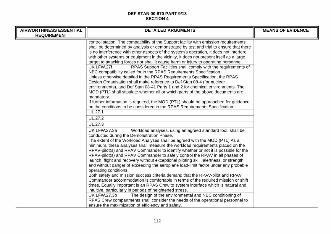
DEF STAN 00-970 PART 9/13 SECTION 4
112
AIRWORTHINESS ESSENTIAL REQUIREMENT
DETAILED ARGUMENTS MEANS OF EVIDENCE
control station. The compatibility of the Support facility with emission requirements shall be determined by analysis or demonstrated by test and trial to ensure that there is no interference with other aspects of the system's operation, it does not interfere with other systems or equipment in the vicinity, it does not present itself as a large target to attacking forces nor shall it cause harm or injury to operating personnel. UK LFW.27f RPAS Support Facilities shall comply with the requirements of NBC compatibility called for in the RPAS Requirements Specification. Unless otherwise detailed in the RPAS Requirements Specification, the RPAS Design Organisation shall make reference to Def Stan 08-4 (for nuclear environments), and Def Stan 08-41 Parts 1 and 2 for chemical environments. The MOD (PTL) shall stipulate whether all or which parts of the above documents are mandatory. If further information is required, the MOD (PTL) should be approached for guidance on the conditions to be considered in the RPAS Requirements Specification. UL.27.1
UL.27.2
UL.27.3
UK LFW.27.3a Workload analyses, using an agreed standard tool, shall be conducted during the Demonstration Phase. The extent of the Workload Analyses shall be agreed with the MOD (PTL) As a minimum, these analyses shall measure the workload requirements placed on the RPAV-pilot(s) and RPAV Commander to identify whether or not it is possible for the RPAV-pilot(s) and RPAV Commander to safely control the RPAV in all phases of launch, flight and recovery without exceptional piloting skill, alertness, or strength and without danger of exceeding the aeroplane load-limit factor under any probable operating conditions. Both safety and mission success criteria demand that the RPAV-pilot and RPAV Commander accommodation is comfortable in terms of the required mission or shift times. Equally important is an RPAS Crew to system interface which is natural and intuitive, particularly in periods of heightened stress. UK LFW.27.3b The design of the environmental and NBC conditioning of RPAS Crew compartments shall consider the needs of the operational personnel to ensure the maximization of efficiency and safety.

DEF STAN 00-970 PART 9/13 SECTION 4
113
AIRWORTHINESS ESSENTIAL REQUIREMENT
DETAILED ARGUMENTS MEANS OF EVIDENCE
The conditions called up in Def Stan 00-35, Health and Safety Legislation shall be considered. When necessary, the use of techniques such as over-pressurisation should be considered in order to meet the requirements of NBC control. This, in turn, will require that all equipment’s within a pressurised zone, including any hermetically sealed units, are capable of operating to their full specifications in their installed conditions. Escape hatches should be outward opening, prominent and have visual indication of their method of operation. They should not be positioned where they may be blocked or partially obscured by equipment inside or outside the Control Station. UK LFW.27.3c Controls and displays shall be developed with User participation. UK LFW.27.3d Where conventional flying controls and displays are employed the form and layout shall be consistent with those of manned aircraft. Reference shall be made to Def Stan 00-970 Part 1 Section 4, Clause 4.10. UK LFW.27.3e Emergency controls (see Def Stan 00-970 Part 1, Section 4, clauses 22 to 24) to be coloured iaw Def Stan 00-970 Part 1 Section 7 requirement 7.4 - OPERATIONAL COLOURING AND MARKINGS UL.27.4
UK LFW.27.4a Antenna Systems - Detection of the Emitter/Receiver by opposing forces shall be minimised. Antenna systems shall be of minimum size and power and maximum directionality consistent with meeting the performance requirements in the RPAS Requirements Specification. Consideration should be given to the remote siting of antennae systems, in order to minimise danger to personnel in the event of attacking forces using the associated radiated energy for targeting or terminal guidance of offensive munitions. UL.27.5
UL.27.6
UL.27.7
UL.28 – Payload
UK LFW.28a The integration of the payload shall be consistent with the
ME.28
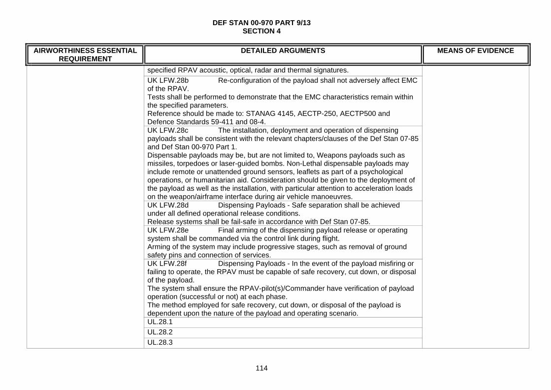
DEF STAN 00-970 PART 9/13 SECTION 4
114
AIRWORTHINESS ESSENTIAL REQUIREMENT
DETAILED ARGUMENTS MEANS OF EVIDENCE
specified RPAV acoustic, optical, radar and thermal signatures.
UK LFW.28b Re-configuration of the payload shall not adversely affect EMC of the RPAV. Tests shall be performed to demonstrate that the EMC characteristics remain within the specified parameters. Reference should be made to: STANAG 4145, AECTP-250, AECTP500 and Defence Standards 59-411 and 08-4. UK LFW.28c The installation, deployment and operation of dispensing payloads shall be consistent with the relevant chapters/clauses of the Def Stan 07-85 and Def Stan 00-970 Part 1. Dispensable payloads may be, but are not limited to, Weapons payloads such as missiles, torpedoes or laser-guided bombs. Non-Lethal dispensable payloads may include remote or unattended ground sensors, leaflets as part of a psychological operations, or humanitarian aid. Consideration should be given to the deployment of the payload as well as the installation, with particular attention to acceleration loads on the weapon/airframe interface during air vehicle manoeuvres. UK LFW.28d Dispensing Payloads - Safe separation shall be achieved under all defined operational release conditions. Release systems shall be fail-safe in accordance with Def Stan 07-85. UK LFW.28e Final arming of the dispensing payload release or operating system shall be commanded via the control link during flight. Arming of the system may include progressive stages, such as removal of ground safety pins and connection of services. UK LFW.28f Dispensing Payloads - In the event of the payload misfiring or failing to operate, the RPAV must be capable of safe recovery, cut down, or disposal of the payload. The system shall ensure the RPAV-pilot(s)/Commander have verification of payload operation (successful or not) at each phase. The method employed for safe recovery, cut down, or disposal of the payload is dependent upon the nature of the payload and operating scenario. UL.28.1
UL.28.2
UL.28.3

DEF STAN 00-970 PART 9/13 SECTION 4
115
AIRWORTHINESS ESSENTIAL REQUIREMENT
DETAILED ARGUMENTS MEANS OF EVIDENCE
UL.29 - Integration ME.29
UL.30 – System Safety Assessment
UK LFW.30a Safety Management for all aspects of the RPAS shall be in accordance with Def Stan 00-56, or an agreed equivalent standard. UL.30.1
UK LFW.30.1a Links to the launcher and launch personnel shall be established such that launch is inhibited until the RPAV-pilot/RPAV Commander is satisfied that all pre-flight checks have been completed and is ready to initiate the launch sequence. Failure Modes Effects and Criticality Analysis (FMECA) shall be carried out to consider all failure modes and their effects on launch procedures. Hazards associated with each failure shall be recorded in the RPAS Hazard Log and addressed in the RPAS Hazard Analysis. Appropriate mitigations shall be taken to reduce these hazards to acceptable levels. Reference should be made to Def Stan 00-56 UL.30.2
UL.30.3
ME.30
UL.31 – Software Development Assurance Levels
UL.31.1
UL.31.2
UL.31.3
UL.31.4
ER.1.3.3
UL.31.5
ME.31
UL.32 – Minimum Display Information
UL.32.1
UL.32.2
UL.32.3
UL.32.4
ME.32
UL.33 – Effectiveness of Displayed Information ME.33
ER.1.3.4
UL.34 – Servicing and Maintenance Information ME.34

DEF STAN 00-970 PART 9/13 SECTION 4
116
AIRWORTHINESS ESSENTIAL REQUIREMENT
DETAILED ARGUMENTS MEANS OF EVIDENCE
UL.35 – External Threats
UL.35.1
UL.35.2
UL.35.3
UL.35.4
UL.35.5
ME.35
UL.36 – Internal Threats
UK LFW.36a Airframes of a specific build standard shall have predictable and repeatable aerodynamic performance. UK LFW.36b Cable runs and connector orientation shall be such as to enable easy and correct connection and disconnection of units in the field. RPAVs may be smaller than their manned equivalents and the environment for servicing may be more severe. Good design of cable runs can obviate damage during servicing. UK LFW.36c Emergency controls (see Def Stan 00-970 Part 1, Section 4, clauses 22 to 24) to be coloured iaw Def Stan 00-970 Part 1 Section 7 requirement 7.4 - Operational Colouring and Markings. UL.36.1
UL.36.2
UL.36.3
UL.36.4
UL.36.5
UL.36.6
UL.36.7
UL.36.7.1
ER.1.3.5
UL.36.7.2
ME.36

DEF STAN 00-970 PART 9/13 SECTION 4
117
AIRWORTHINESS ESSENTIAL REQUIREMENT
DETAILED ARGUMENTS MEANS OF EVIDENCE
ER.1.4 – Continued Airworthiness of the UAS
UL.37 – Instructions for Continued Airworthiness UL.37.1
UL.37.2
UK LFW.37.2a Any permitted repairs shall ensure that the structural and aerodynamic integrity of the airframe is not degraded and that the airworthiness and safety of the operation of the system is not degraded. The RPAV Design Organisation should define the extent and scope of acceptable repairs, taking account of primary, secondary and tertiary structures; in addition the RPAS Requirement Specification should state the service conditions in which repairs are expected to be undertaken. UL.37.3
UL.37.4
UL.37.5
UL.37.6
ER.1.4.1
UL.37.7
ME.37
ER.1.4.2 UL.38 – Means for Continued Airworthiness
ER.1.4.3 See UL.37 and ME.37
ME.38
ER.1.4.4 UL.39 – Airworthiness Limitations Section ME.39

DEF STAN 00-970 PART 9/13 SECTION 4
118
AIRWORTHINESS ESSENTIAL REQUIREMENT
DETAILED ARGUMENTS MEANS OF EVIDENCE
ER.2 – Airworthiness Aspects of System Operation
ER.2.1 See the Following
UL.40 – Kinds of Operation UK LFW.40a The permitted operating envelopes for all given build standards and role configurations of the RPAV shall be declared. The basic flight envelope shall be defined graphically, without ambiguity, in a recognised format. The Basic Flight Envelope, should be expressed in terms of principal parameters such as Equivalent Airspeed (EAS), altitude and normal acceleration (normal load factor as a multiple of G), or any alternative format which more appropriately or more clearly defines those mission requirements of most concern. The effects of RPAV mass properties, role configuration and atmospheric/environmental conditions should be considered. UL.40.1
UL.40.2
ME.40
UL.41 – Stalling Speeds
UL.41.1
UL.41.2
UL.41.3
UL.41.4
ME.41
UL.42 – Takeoff/Launch
UK LFW.42a Air Launch - RPAVs that are to be launched from manned aircraft in flight shall comply with the requirements for weapons carriage and release as stated in Def Stan 00-970, Part 13 Section 3, Clause 3.1
ER.2.1.1
UK LFW.42b Pressurised gas systems shall be designed to the requirements of Def Stan 00-970 Part 1 Section 6, Clause 6.14, (See also, Section 6 Clause 6.12, BS-4N100:1 , Def Stan 81-24 and BS EN 1803. The operating performance and reliability of stored energy catapult systems are particularly susceptible to environmental extremes such as heat, cold and the ingress of
ME.42

DEF STAN 00-970 PART 9/13 SECTION 4
119
AIRWORTHINESS ESSENTIAL REQUIREMENT
DETAILED ARGUMENTS MEANS OF EVIDENCE
moisture or contaminants.
UK LFW.42c Rocket Assisted Takeoff (RATO) - The storage, transportation, handling, testing and operation of the RATO units shall be in undertaken following the safety guidance advice from DOSG. Any device intended to restrain the air vehicle shall be capable of doing so for the highest possible motor thrust, and should preferably isolate the electrical initiation circuit to the rocket motor. Design loads for RATO launch systems should take into account the stochastic variation in solid propellant characteristics and the most adverse environmental conditions. RATO launch involves the acceleration of the air vehicle from a support stand or via a short ground run by means of a rocket booster. The booster may be temporarily affixed to the RPAV to enable launch and may be released or jettisoned at the end of burn. Where asymmetric thrust and/or active flight controls during launch are possible, loads induced by these systems should be catered for in the design of the RATO Launch system. UK LFW.42d RATO - Any failure of the RATO system shall not result in a hazardous situation, or pose a safety hazard to personnel. Hazard analysis of the launch system should include: failure to ignite, asymmetric ignition, late ignition and partial thrust. DOSG should be consulted for guidance. UK LFW.42e RATO - The Launcher system, platform or personnel shall be protected from the effects of rocket plume impingement at launch and any debris emitting from the rocket motor. The use of suitable materials, blast shields and safety procedures shall be implemented. UL.42.1
UL.42.2
UL.42.3
UL.42.4
UK LFW.42.4a Including Carousel Launch. UL.42.5 UL.42.6
UL.42.7

DEF STAN 00-970 PART 9/13 SECTION 4
120
AIRWORTHINESS ESSENTIAL REQUIREMENT
DETAILED ARGUMENTS MEANS OF EVIDENCE
UL.42.8
UL.43 – Climb and Descent UL.43.1
UL.43.2 UL.43.3 UL.43.4
ME.43
UL.44 – Navigation Accuracy UL.44.1 UL.44.2 UL.44.3
ME.44
UL.45 - Glide UL.45.1 UL.45.2
ME.45
UL.46 - Landing UL.46.1 UL.46.2 UL.46.3 – Conventional Landing UL.46.4 – Recovery with Parachute UK LFW.46.4a The routing of parachute attachment strops shall be unambiguous. Instructions for routing of parachute strops shall be marked on the airframe and strops or highlighted in appropriate servicing manuals. UL.46.5 – Recovery by Arrestment UK LFW.46.5a Recovery Systems - Where required, the design of the system shall include use of surface restraining systems such as deck locks on board ship. Airborne system safety factors shall be the subject of agreement between the RPAS Design Organisation and the MOD (PTL) with surface based equipment having an ultimate factor of safety of at least 4.0 UL.46.6 UL.46.7 UL.46.8
ME.46
ER.2.1.2 UL.47 – Controllability and Manoeuvrability ME.47

DEF STAN 00-970 PART 9/13 SECTION 4
121
AIRWORTHINESS ESSENTIAL REQUIREMENT
DETAILED ARGUMENTS MEANS OF EVIDENCE
UL.47.1 UL.47.2 UL.47.3 UK LFW.47.3a Reversionary navigation capability shall be provided to ensure safety of flight. The needs for, and performance requirements of, separate navigation systems shall be established in the RPAS Safety Case and specified in the RPAS Requirements Specification. Alternative navigation sensors listed under Guidance shall be considered. The following should be considered as reversionary navigation sensors: Dead reckoning from fluxgate and air data, communication/data links range and bearing, terrain referenced navigation and scene matching navigation. The choice may depend on terminal navigation requirements derived from mission success criteria. UL.47.4 UL.48 - Trim ME.48 UL.49 – Minimum Control Speed ME.49 UL.50 - Stability UL.50.1 UL.50.2 UL.50.3 UL.50.4 UL.50.5
ME.50
UL.51 – DUO Workload UK LFW.51a The RPAS shall comply with the requirements of Def Stan 00-250 Human Factors for Designers of Systems. As agreed between the RPAS Design Organisation and the MOD (PTL)
ME.51
ER.2.1.3 UL.52 – Flight Phase Transition ER.2.1.4 Not Applicable
ME.52
ER.2.1.5 UL.53 – Emergency recovery Capability UK LFW.53a Flight Termination - Safety and Reliability: The RPAS
Requirements Specification shall identify any operational scenarios where the normal function of the FTS is to be inhibited. Conditions in which it may be necessary to inhibit the operation of the FTS may include the period immediately after launch when it is necessary to achieve a safe
ME.53

DEF STAN 00-970 PART 9/13 SECTION 4
122
AIRWORTHINESS ESSENTIAL REQUIREMENT
DETAILED ARGUMENTS MEANS OF EVIDENCE
separation distance from the launch platform, any period during recovery or retrieval when operation of the FTS could increase the risk to personnel or third parties being overflown or within the vicinity or if launch has been inhibited after propulsion system ignition. UK LFW.53b Flight Termination - The RPAS Requirement Specification shall state the extent to which the FTS shall be resistant to internal and external interference including jamming - See Clause UK 20b UL.53.1 UL.53.2 UL.53.3 UL.54 – Conflict Avoidance manoeuvres ME.54 UL.55 – Engine Shut Down Procedure UL.55.1 UL.55.2 UL.55.3
ME.55
UL.56 – Flight manual ME.56 UL.57 – Flight Envelope Design UL.57.1 UL.57.2 UL.57.3 UL.57.4 UL.57.5 UL.57.6
ME.57
UL.58 – Flight Envelope Protection UL.58.1 UL.58.2
ER.2.1.6
UL.58.3
ME.58
ER.2.1.7 UL.59 – Flight Envelope Extremes Test ME.59 ER.2.2 UL.60 – Flight Manual ER.2.3 See UL.35 and UL.36 ER.2.3.1 See UL.35 and UL.36
ME.60
ER.2.3.2 Not Applicable Not Applicable ER.2.3.3 See UL.27, UL.32 and UL.33 ME.60
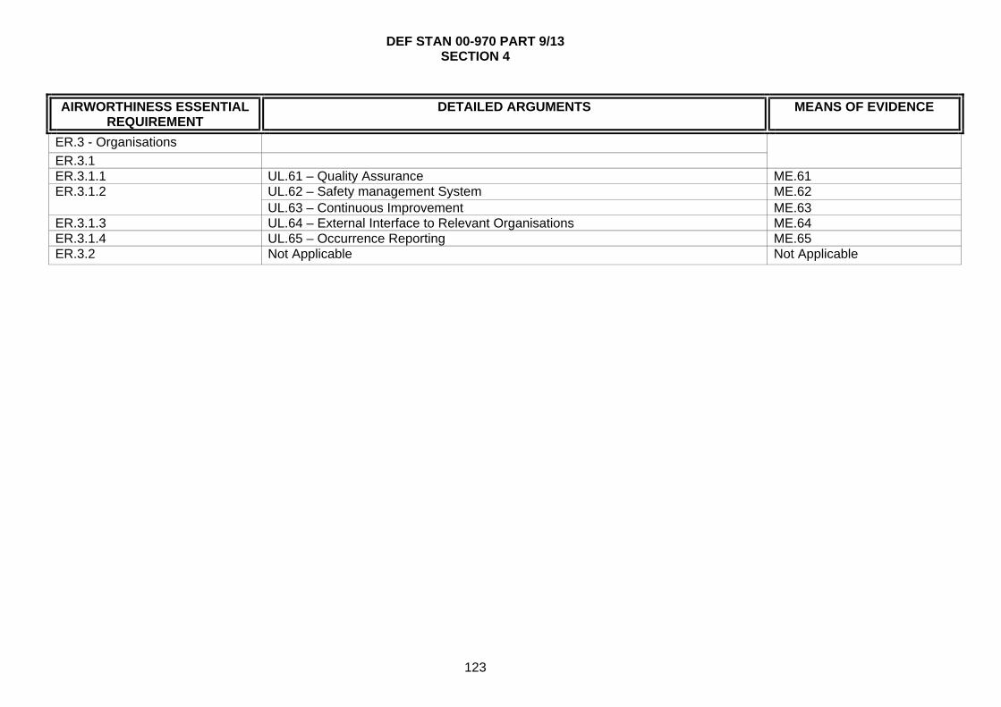
DEF STAN 00-970 PART 9/13 SECTION 4
123
AIRWORTHINESS ESSENTIAL REQUIREMENT
DETAILED ARGUMENTS MEANS OF EVIDENCE
ER.3 - Organisations
ER.3.1
ER.3.1.1 UL.61 – Quality Assurance ME.61 UL.62 – Safety management System ME.62 ER.3.1.2 UL.63 – Continuous Improvement ME.63
ER.3.1.3 UL.64 – External Interface to Relevant Organisations ME.64 ER.3.1.4 UL.65 – Occurrence Reporting ME.65 ER.3.2 Not Applicable Not Applicable

DEF STAN 00-970 PART 9/13 SECTION 4
124
AIRWORTHINESS ESSENTIAL REQUIREMENT
DETAILED ARGUMENTS MEANS OF EVIDENCE
UL.66 – UA Handover between two UCS/UCB
UL.66.1
UL.66.2
UL.66.3
UL.66.4
UL.66.5
ME.66
UL.67 – UCS/UCB Control of Multiple UA
UL.67.1
UL.67.2
UL.67.3
UL.67.4
ME.67
UL.68 – UCS with more than one Workstation for controlling the UA
UL.68.1
UL.68.2
UL.68.3
UL.68.4
UL.68.5
ME.68
UA Handover
UL.69 – UCS/UCB Monitoring of Multiple UA ME.69

DEF STAN 00-970 PART 9/13 SECTION 4
125
AIRWORTHINESS ESSENTIAL REQUIREMENT
DETAILED ARGUMENTS MEANS OF EVIDENCE
Annex A – Terms and Definitions
Annex B - Landing Conditions for Conventional Landing Gear Configurations (Where Applicable)
Annex C – Spark and Compression Ignition Reciprocating Engines
Annex D – Electric Engines
Annex E – Turbine Engines
Annex F - Propellers
Annex G – Hazard Reference System
Annex H – Stability and Response Assessment Guidance
Annex I – The Safety Management Plan
Annex J – Guidelines for Airworthiness Requirements Applicable to UA below the 66J Impact Energy

©Crown Copyright 2015
Copying Only as Agreed with DStan
Defence Standards are published and obtainable from:
Defence Equipment and Support UK Defence Standardization
Kentigern House 65 Brown Street
Glasgow G2 8EX
DStan Helpdesk:
Tel: 44 (0) 141 224 2531/2
Fax: 44 (0) 141 224 2503
Internet e-mail: [email protected]
File Reference
The DStan file reference relating to work on this standard is D/DStan/21/970/9 Contract Requirements
When Defence Standards are incorporated into contracts users are responsible for their correct application and for complying with contractual and statutory requirements. Compliance with a Defence Standard does not in itself confer immunity from legal obligations. Revision of Defence Standards
Defence Standards are revised as necessary by an up issue or amendment. It is important that users of Defence Standards should ascertain that they are in possession of the latest issue or amendment. Information on all Defence Standards can be found on the DStan Website www.dstan.mod.uk, updated weekly and supplemented regularly by Standards in Defence News (SID News). Any person who, when making use of a Defence Standard encounters an inaccuracy or ambiguity is requested to notify UK Defence Standardization (DStan) without delay in order that the matter may be investigated and appropriate action taken. Sponsors and authors shall refer to Def Stan 00-00 before proceeding with any standards work.
®


![Singapore Airworthiness Requirements · SINGAPORE AIRWORTHINESS REQUIREMENTS CONTENTS 1 NOV 2018 [REV 29] CIVIL AVIATION AUTHORITY OF SINGAPORE C-3 SECTION 5 - AIRCRAFT PERFORMANCE](https://img.pdfslide.net/doc/110x75/5e4ef41da2f97d51ee7557cd/singapore-airworthiness-requirements-singapore-airworthiness-requirements-contents.jpg)