Embed Size (px)
Citation preview

International Journal of Application or Innovation in Engineering & Management (IJAIEM) Web Site: www.ijaiem.org Email: [email protected], [email protected]
Volume 3, Issue 1, January 2014 ISSN 2319 - 4847
Volume 3, Issue 1, January 2014 Page 223
ABSTRACT In this paper, Minkowski fractal antenna for Bluetooth application has been designed. Apart from this, it can be used for various other applications as well because of its multiband feature. The antenna is fed by Microstrip feeding technique. Its advantage is that it can be easily fabricated as it is a just conducting strip connecting to the patch and therefore, can be considered as an extension of the patch. The proposed patch antenna is designed and simulated on IE3D simulation software and it is designed to operate in 2.45GHz band. Dielectric substrate with the permittivity €=2.2 (RT/Duroid 5880) with width of 1.588mm is used to make a resonant patch antenna of linear polarization. In this analysis, we have compared the antenna parameters such as gain, impedance, antenna efficiency, radiation efficiency, radiation pattern, polar plots, VSWR and Q-factor. Reduction in patch antenna size is achieved when performing fractalization of the main patch. General Terms: Microstrip patch antenna, Minkowski Fractal Antenna, Microstrip feed Keywords: Radiation pattern, VSWR, Directivity, 2D Polar Plot, Return loss, Fractal Antenna,
1. INTRODUCTION The concept of microstrip radiators, introduced by Deschamps in 1953, remained dormant until the late 1970s when low-profiles antennas were required for an emerging generation of missiles [1], [2]. However, first practical antennas were developed by Munson [3] and Howell in the 1970s. Since then, extensive research and development of microstrip antennas and arrays, aimed at exploiting their numerous advantages such as low profile, light weight, conformable to planer & non-planer surfaces, compatibility with integrated circuits, mechanically robust, have an ease of fabrication and so on, which led to diversified applications and to the establishment of the topic as a separate entity within the broad field of microwave antennas [4]. In last 40 years, the microstrip antennas have been developed for various communication systems such as radars, sensors, wireless, satellite, broadcasting, ultra-wideband, radio frequency identification (RFIDs), reader devices etc. But a low bandwidth can be achieved with simple microstrip antennas and advanced communication systems require antennas with more bandwidth and smaller dimensions as compared to conventional antennas. Various desirable features like smaller size, multi-band and broad-band properties can be easily achieved by using fractal geometry-based antennas. Fractals have self-similar shapes and can be subdivided into parts such that each part is a reduced size copy of the whole.
2. MICROSTRIP PATCH ANTENNA
2.1 INTRODUCTION A microstrip antenna mainly consists of a single ground plane and an open strip conductor separated by dielectric substrate as shown in the fig. 1. It is constructed by the photographic processed used for integrated circuits [13]. The most commonly used microstrip element consists of a rectangular element that is photoetched from one side of a printed-circuit board. However, other shapes, such as the square, circular, triangular, semicircular, sectoral and annular ring shapes can also be possible [5]. Microstrip antennas shown as in fig. 1, consists of a very thin [11] (t<<λo where λo is a free-space wavelength) metallic strip (patch) placed at a small fraction of a wavelength (h<< λo usually 0.003 λo ≤ h ≤ 0.05 λo) above a ground plane. This is accomplished by properly choosing the mode (field configuration) of excitation beneath the patch. For a rectangular patch, the length L of the element is usually λo/3 < L < λo/2. The strip and ground plane are separated by a dielectric sheet usually referred to as the substrate. The dielectric constants are usually in the range of 2.2 ≤ €r ≤ 12.
DESIGN AND ANALYSIS OF MINKOWSKI FRACTAL ANTENNA USING
MICROSTRIP FEED
Munish Kumar1
1M-Tech Electronics and Communication, Department of ECE, USICT, G.G.S. Indraprastha University, New Delhi

International Journal of Application or Innovation in Engineering & Management (IJAIEM) Web Site: www.ijaiem.org Email: [email protected], [email protected]
Volume 3, Issue 1, January 2014 ISSN 2319 - 4847
Volume 3, Issue 1, January 2014 Page 224
Figure 1 Typical geometry of a Microstrip Antenna
2.2 EFFECT OF DIMENSIONS AND OTHER FACTORS ON ANTENNA PARAMETERS ARE AS FOLLOWS: The width, W of the patch can be taken smaller or larger than the value obtained using equation (4.1). If W is
smaller, then the bandwidth and gain both will degrade. If W is larger, BW increases due to increase in the radiated fields. The directivity increases due to increase in the aperture area. However, if W is too large, then the higher order modes could be excited [5], [7], [11].
As the W increases, it not only affects gain and bandwidth, but also affects the resonant frequency as well. Resonant frequency decreases due to decrease in ∆L and €eff [5].
Input impedance also decreases as W increases because the radiation from the radiating edge increases, which decreases the radiation resistance [5].
The aperture area of the antenna increases as W increases; resulting in the increase in the directivity, efficiency and hence, gain. The HPBW in the H-plane decreases, whereas it remains almost same in the E-plane, because the increase in the width is in the H-plane [5].
As the ‘h’ or substrate height increases, the fringing fields from the edges increase, which increases the extension in the length ∆L and hence, the effective length, thereby decreasing the resonant frequency. On the other hand, as ‘h’ increases, the W/h ratio reduces, which decreases €eff and hence increases the resonant frequency. However, the effect of the increase in ∆L is dominant over the decrease in €eff. Therefore, the net effect is to decrease the resonant frequency [5].
The BW of the antenna increases as ‘h’ increases [5], [7]. The efficiency also increases with an increase in the substrate thickness or ‘h’ [5], [7].
3. FRACTAL ANTENNAS
3.1INTRODUCTION Fractals (term coined by Benoit Mandelbrot in 1975, derived from Latin word fractuss, meaning “broken” or “fractured”) are highly convoluted and jagged shapes that can be subdivided in parts, each of which is (at least approximately) a reduced-size copy of the whole. These are nature inspired antennas. The discontinuities in these antennas causes increase in bandwidth and effective radiation.
3.2MAJOR VARIATIONS OF FRACTALS Fractals come into two major variations:
Deterministic (chaotic) fractal: It consists of those fractals that are composed of several scaled down and rotated copies of itself, such as Koch curve (fig. 2.a). They are also called geometric fractals. They exhibit the property of self symmetry.
Random fractal: It includes those fractals which have an additional element of randomness allowing for simulation of natural phenomenon, so they exhibit property of statistical self similarity. They look like random walks (Brownian motion), dendrites or lightning bolts.
3.3 MINKOWSKI FRACTAL ANTENNA Fractal antennas can take on various shapes and forms. There are many mathematical structures that are fractals; e.g. Sierpinski’s Carpet, Sierpinski’s gasket, Cantor’s comb, von Koch’s snowflake, the Mandelbrot set, Minkowski square loop and hexagonal etc.

International Journal of Application or Innovation in Engineering & Management (IJAIEM) Web Site: www.ijaiem.org Email: [email protected], [email protected]
Volume 3, Issue 1, January 2014 ISSN 2319 - 4847
Volume 3, Issue 1, January 2014 Page 225
Minkowski gasket is one of the earliest structures of fractal geometry. A miniaturization of loop antenna using the fractal technique is known as Minkowski square loop antenna.
Figure 2 Construction of the Minkowski-like fractal structure [17]
a.) The generator b.) First Iteration c.) Square patch antenna (Initiator)
3.4 SPECIAL PROPERTIES OF FRACTALS Fractal antennas have some very special properties that make them attractive for the design of small antennas. These properties are [17], [20]:
Broad band operation: The fractals antennas radiate and detect efficiently within a wide range of frequencies. The frequency range is specified by the smallest and largest size present in the antenna. The radiation pattern and hence, the detection efficiency do not vary much as a function of frequency.
Gain: the fractal antennas can display a gain which depends slowly on frequency over a large frequency range. Spatial structure: The fractal antennas can display a spatial structure which is also related to the antenna gain, as
the antenna concentrates certain power in certain positions and not in others. Space filling and multiple scale properties: Fractal antennas can place long electrical length into small volume
only because of this property. Self-similar pattern: Because one should expect a self-similar (at least approximately or stochastically) antenna
(which contains many copies of itself at several scales) to operate in a similar way at several wavelengths. That is, the antenna should keep similar radiation parameters through several bands.
Mechanical simplicity and robustness: The characteristic of fractal antenna are obtained due to its geometry and not by the addition of discrete components.
4. DESIGN METHODOLOGY
a. DESIGN PROCEDURE a.) The width of the microstrip antenna can be calculated as
W = (4.1)
= 48.4mm b.) For low frequencies, the effective dielectric constant is essentially constant; but at intermediate frequencies, its
values begin to monotonically increase and eventually approach the values of the dielectric constant of the substrate. It is given by the expression as follows:
εeff =
= 2.1082 c.) Due to the fringing effect, electrically the patch of the microstrip antenna looks greater than its physical
dimensions. So, first we will calculate the extra length which is extended on each side of the patch along its
International Journal of Application or Innovation in Engineering & Management (IJAIEM) Web Site: www.ijaiem.org Email: [email protected], [email protected]
Volume 3, Issue 1, January 2014 ISSN 2319 - 4847
Volume 3, Issue 1, January 2014 Page 226
length. It is given by the following expression:
∆L =
= 0.84mm d.) After that, we will calculate the effective length of the patch, which is given by:
Leff =
= 41.27754mm e.) So, the actual length of the rectangular patch can be determined as follows:
L = Leff – 2(∆L) == 40.49mm
ff..)) IInnppuutt iimmppeeddaannccee ooff tthhee ppaattcchh ccaann bbee ggiivveenn aass::
Za =
= 225544..0044Ω gg..)) CChhaarraacctteerriissttiicc iimmppeeddaannccee ooff tthhee ttrraannssiittiioonn sseeccttiioonn sshhoouulldd bbee::
Zo = = 122.69 Ω
h.) Transition line width can be calculated by using the formula:
Zo =
WT = 0.615mm i.) Transition line length can be calculated as:
εre =
= 1.706 Hence, the length of the transition should be:
=
= 23.437mm j.) Width of 50 Ω microstrip line feed can be calculated as:
Zc =
50 =
So, Wm = 4.367mm
The final rectangular patch antenna will look as follows:
Figure 3 A reference patch antenna for 2.45GHz with 0 iteration
International Journal of Application or Innovation in Engineering & Management (IJAIEM) Web Site: www.ijaiem.org Email: [email protected], [email protected]
Volume 3, Issue 1, January 2014 ISSN 2319 - 4847
Volume 3, Issue 1, January 2014 Page 227
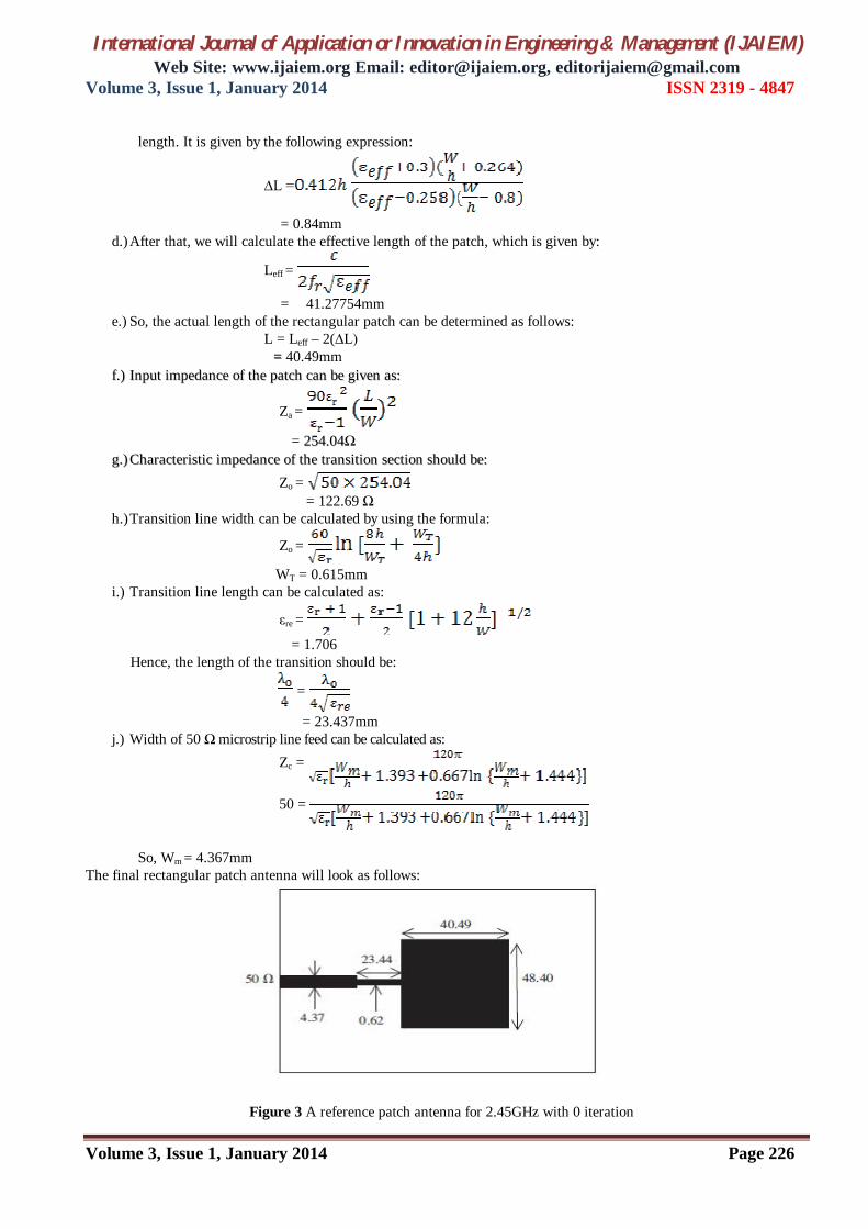
IInniittiiaallllyy,, ssiimmuullaattiioonn ooff tthhee aaccttuuaall ppaattcchh ((wwiitthh 00 iitteerraattiioonn)) hhaass bbeeeenn ddoonnee.. FFiirrsstt ooff aallll,, wwiiddtthh WW22 iiss vvaarriieedd ffoorr ffiixxeedd vvaalluuee ooff WW11 ((ssaayy 11mmmm)).. AAss ppeerr oouurr ssiimmuullaattiioonn rreessuullttss,, bbeesstt rreessuullttss hhaavvee ccoommee oonn WW22 == 88mmmm.. AAfftteerr tthhaatt WW11 iiss vvaarriieedd ffoorr ffiixxeedd vvaalluuee ooff WW22 ((==88mmmm))..
5. SIMULATION RESULTS AND DISCUSSION The iterations of the microstrip patch antenna were examined by using the IE3D simulation software tool. The frequency lies between (1GHz-5GHz) upto 1000 number of frequencies. The simulation of this antenna structure provides good results and makes this antenna suitable to work in 4 different frequency bands. 5.1 WHEN W2 IS VARIED AND W1 IS KEPT CONSTANT Simulation results for WW11 =1mm and WW22 =1mm, 2mm, 4mm, 8mm, 10mm, 12mm, 19.475mm and 23.7mm (beyond that is not possible) are as follows (for W1 and W2, see fig.2).
Figure 4 Minkowski Fractal Antenna with same value of W1 and different values of W2.

International Journal of Application or Innovation in Engineering & Management (IJAIEM) Web Site: www.ijaiem.org Email: [email protected], [email protected]
Volume 3, Issue 1, January 2014 ISSN 2319 - 4847
Volume 3, Issue 1, January 2014 Page 228
Here, ‘unequal cuts’ (last antenna of fig.4) refers to the case when the cuts along the L and W are not same, i.e. here it is 23.7 along the W and 19.745 along the L. In last, a comparison table (Table 1) is made for better understanding. For more clarity, simulation results for only few values of W2 are shown in the below figures.
Figure 5 S11 Display (dB) Figure 6 VSWR Display
Figure 7 Antenna Efficiency Figure 8 Radiation Efficiency

International Journal of Application or Innovation in Engineering & Management (IJAIEM) Web Site: www.ijaiem.org Email: [email protected], [email protected]
Volume 3, Issue 1, January 2014 ISSN 2319 - 4847
Volume 3, Issue 1, January 2014 Page 229
Figure 99 TToottaall GGaaiinn ((ddBBii)) Figure 1100 DDiirreeccttiivviittyy ((ddBBii))
5.2 WHEN W1 IS VARIED AND W2 IS KEPT CONSTANT Similarly, if we vary the W1, we will get the different results. Simulation results for WW22 =8mm and WW11 =1mm, 2mm, 4mm, 8mm, 12mm (for W1 and W2, see fig.2) are as follows. Comparison table (Table 2) for the same is also given after the simulation results.
Figure 11 Minkowski Fractal Antenna with same value of W1 and different values of W2.

International Journal of Application or Innovation in Engineering & Management (IJAIEM) Web Site: www.ijaiem.org Email: [email protected], [email protected]
Volume 3, Issue 1, January 2014 ISSN 2319 - 4847
Volume 3, Issue 1, January 2014 Page 230
Figure 12 Antenna Efficiency Figure 13 Radiation Efficiency
Figure 14 Total Gain (dBi) Figure 15 Directivity (dBi)

International Journal of Application or Innovation in Engineering & Management (IJAIEM) Web Site: www.ijaiem.org Email: [email protected], [email protected]
Volume 3, Issue 1, January 2014 ISSN 2319 - 4847
Volume 3, Issue 1, January 2014 Page 231
Figure 16 S11 Display (dB) Figure 17 VSWR Display
Table 1: Comparison table when W1 is constant & W2 is varied.

International Journal of Application or Innovation in Engineering & Management (IJAIEM) Web Site: www.ijaiem.org Email: [email protected], [email protected]
Volume 3, Issue 1, January 2014 ISSN 2319 - 4847
Volume 3, Issue 1, January 2014 Page 232
Table 2: Comparison table when W2 is constant & W1 is varied.
G=Gain, D=Directivity, B.W= bandwidth, A.E=Antenna Efficiency, R.E=Radiation Efficiency
6. CONCLUSION
Minkowski fractal antenna upto 1st iteration with microstrip feed has been designed and simulated using IE3D ver.14.0. As W2 starts increasing (keeping W1=1mm), the results were fine upto W2=8mm; but starts deteriorating beyond that. So we are getting best results at W1=1mm & W2=8mm and hence this patch has been taken as the reference patch for our next simulation where W1 starts changing and keeping W2 constant. Before making the main patch fractal, the bandwidth was 11.45MHz. However after making it fractal, the bandwidth has been enhanced to 18.9MHz for the same resonant frequency. Along with bandwidth, return loss (S11) parameter also gets reduced to -24.9774dB from -10.9726dB, gain increases to 5.16dBi from 5.12dBi and antenna efficiency to 69.7% from 60.7%, which clearly indicates the advantages of making the patch fractal. We can further enhance the performance of the antenna by performing 2nd iteration over it. Since the number of frequency bands are 4 i.e. 1.8689GHz, 2.19319GHz, 4.043GHz and 4.599GHz; so the proposed Minkowski antenna can be used in various other applications as well apart from the Bluetooth like UMTS, GSM and other industrial, medical and scientific applications. So in future, Minkowski fractal antenna upto 2nd iteration with EBG will be designed and simulated for the same resonant frequency in order to achieve better gain, bandwidth etc which will make it suitable for other applications as well.
REFERENCES [1] James J.R. & Hall P.S. (1989). Handbook of Microstrip Antennas, Peter Peregrinus, ISBN: 0-86341-150-9, London [2] James J.R. & Hall P.S., and Wood C, “Microstrip antennas-theory and design”, London: Peregrinus, 1981. [3] Munson, R. E., ‘‘Conformal Microstrip Antennas and Microstrip Phased Arrays’’ IEEE Trans. Antennas
Propagation, Vol. AP-22, 1974, pp. 74–78. [4] Bahl, I.J., P. Bhartia, Ramesh Garg, Apisak Ittipiboon, Microstrip Antenna Design Handbook, Dedham, MA: Artech
House, Inc. Canton Street, Norwood, 2001. [5] Girish Kumar and K.P. Ray, Broadband Microstrip Antennas, Artech House, ISBN: 1-58053-244-6, Boston,
London. [6] Qian, Y., et al., “Microstrip Patch Antenna Using Novel Photonic Bandgap Structures,” Microwave J., Vol.42, Jan.
1999, pp. 67-76 [7] Bahl, I.J., and P. Bhartia, Microstrip Antennas, Dedham, MA: Artech House, 1980. [8] S.A. Long and M.D. Walton, “A Dual-Frequency Stacked Circular-Disc Antenna,” IEEE Trans. Antennas
Propagation, Vol. AP-27, No. 2, pp. 270-273, March 1979. [9] James, J.R., and P.S. Hall, Handbook of Microstrip Antennas, Vol. 1, London: Peter Peregrinus Ltd., 1989.
Dimensions fr S11(dB) VSWR G
(dBi)
A.E and R.E.
(%)
D
(dBi)
B.W.
(MHz)
No. of bands
1mm 8mm 2.19319 -24.9774 1.11945 5.161 69.70,69.7 7.21526 18.90 4
2mm 8mm 2.17316 -24.4130 1.12778 5.930 78.9,86.49 7.18957 18.71 4
4mm 8mm 2.14115 -21.9151 1.17442 1.064 30.83,85.1 7.16057 17.8981 4
8mm 8mm 2.10907 -15.6177 1.39692 4.957 68.3,84.35 7.10668 15.0245 2
12mm 8mm 2.10917 -12.6528 1.60789 4.187 58.9,83.16 7.07843 11.228 1

International Journal of Application or Innovation in Engineering & Management (IJAIEM) Web Site: www.ijaiem.org Email: [email protected], [email protected]
Volume 3, Issue 1, January 2014 ISSN 2319 - 4847
Volume 3, Issue 1, January 2014 Page 233
[10] Richard C. Johnson, Henry Jasik, “Microstrip Antennas” in Antenna Engineering Handbook, 3rd ed. New York, McGraw-Hill, Inc., ch. 7, sec. 3, pp. 7-19
[11] C.A. Balanis, “Advanced Engineering Electromagnetics”, New York, John Wiley and Sons, 1989 [12] IE3d Manual, Zealand Software Inc. Freemont, California, U. S. A., 1999. [13] Mathew N.O. Sadiku , “Transmission Lines” in Principles of Electromagnetics, 4th ed. Oxford University Press, ch.
10, sec.10.7, pp. 474-478 [14] Ansoft Corporation HFSS. http://www.ansoft.com/products/hf/hfss. 2004 [15] B.B. Mandelbrot, “The Fractal Geometry of Nature” San Francisco, CA: Freeman, 1983 [16] Douglas H. Werner and Suman Ganguly, “An overview of Fractal Antenna Engineering Research Communications
and Space sciences laboratory”, Department of Electrical Engineering, the Pennsylvania state University, University Park, PA 16802, USA
[17] Dhrgham. K. Naji, Jaber. S. Aziz and Raad S. Fyath, “Design and simulation of RFID Aperture Coupled Fractal Antennas”, Department of Electronics and Communication Engineering, College of Engineering, Al-Nahrain University, Baghdad-Iraq
[18] Philip Felber. Fractal Antennas. A literature study as a project for ECE 576, Illinois Institute of Technology December 12, 2000 (Revised: January 16, 2001)
[19] X. Yang, J. Chiochetti, D. Papadopoulos and L. Susman, “Fractal Antenna Elements and Arrays”, Applied Microwave & Wireless, APTI Inc.
[20] Neetu, Savina Bansal and R. K. Bansal, “Design and analysis of fractal antennas based on Koch and Sierpinski fractal geometries”, Department of Electronics and Communication, PTU GZS campus, Bhatinda.
[21] Cohen. N.L., “Fractals’ new era in military antenna design” [22] David A. Sanchez-Hernandez, “Printed Multiband Fractal Antennas” in Multiband Integrated Antennas for 4G
Terminals, Artech House, London, pp 97-117 [23] S.B. Kumar, “Analysis of Multiband Band Microstrip Fractal Antenna” National Conference Sponsored By IETE,
GWALIOR (M.P.). [24] “Electromagnetic Band Gap Structures in Antenna Engineering” Fan Yang, University of Mississippi and Yahya
Rahmatt Samii, University of California (Los Angeles). [25] M. Fallah, F. H. Kashani, and S. H. Mohseni, “Side Effect Characterization Of EBG Structures in Microstrip
Antennas” Progress In Electromagnetics Research Symposium Proceedings, Cambridge, USA, July 5-8, 2010, pp 323-326.
AUTHOR Munish Kumar received the B-Tech degree in Electronics and Communication Engineering from Bharati Vidyapeeth’s College of Engineering, New Delhi in 2011 and published one of his papers ‘Analysis of Sierpinski’s gasket multiband fractal antenna’ in National Conference on Electronics and Communication held in MITS in 2010, Gwalior, MTTS IEEE Council. Now, he is receiving M-Tech degree from USICT,
Guru Govind Singh Indraprastha University, New Delhi in Electronics and Communication. During 2011-2013, he worked with HCL Technologies Limited as a software engineer. His research interest is in the area of Electromagnetic theory, Mobile and Wireless Communication, Microstrip Antennas & propagation, Fiber optics and Optics, and Fractals antennas.


![MICROSTRIP PATCH ANTENNA OPTIMIZATION US- ING … · IE3D is a full wave EM simulator [15] in which Maxwell’s integral equations are solved using the frequency-domain method of](https://img.pdfslide.net/doc/110x75/5e68090653db16443a374bf5/microstrip-patch-antenna-optimization-us-ing-ie3d-is-a-full-wave-em-simulator-15.jpg)