Embed Size (px)
Citation preview

DESIGN AND FABRICATION OF POTHOLE DETECTION
AND LEVELLING ROBOT
MINI PROJECT REPORT
Submitted by
ROHITH V L
YOGESH R
VARUN VINAYEK J
VASUDEVAN P
MECHATRONICS ENGINEERING
SRI KRISHNA COLLEGE OF
ENGINEERING AND TECHNOLOGY
(An Autonomous Institution)
(Approved by AICTE and Affiliated to Anna University,
Chennai)
ACCREDITED BY NAAC WITH ‘A’ GRADE
APRIL 2018

ii
ABSTRACT
The main objective of the project is to design and fabricate an Semi-
Automated Robot,which will detect the Pothole on the road and will
discharge the required amount on concrete quantity,which is needed for the
detected pothole and to do the levelling process on the discharged concrete
and hence the pothole on the road filled completely.
The power source for the robot is switched ON and allows the robot to
move on the road.The Ultrasonic sensor on the front of the robot is allowed
to sense the surface of the road, if the pothole will be detected the sensor send
the signals to the Arduino Controller, and the controller suddenly stops the
movement of robot near the pothole, and allows to discharge the required
concrete needed for the detected pothole.Then after filling the pothole the
slider crank mechanism is used for levelling process.
KEYWORDS: Ultrasonic sensor, Slider crank mechanism, Levelling, Semi
automated robot.

TABLE OF CONTENTS iii
CHAPTER TITLE PAGE
NO. NO.
ABSTRACT ii
TABLE OF CONTENTS iii
LIST OF TABLES v
LIST OF FIGURES vi
1 INTRODUCTION 1
1.1 INTRODUCTION 1
1.2 OBJECTIVE OF PROJECT WORK 2
1.3 ORGANISATION OF CHAPTERS 3
1.4 CONCLUSION 4
2 LITERATURE REVIEW 5
2.1 INTRODUCTION 5
2.2 POTHOLE-DEFINITION 5
2.3 AUTOMATED PATCHING 6
2.4 VISION EVALUATIONS 6
2.4.1 Remote Manipulator Evaluations 6

vi
2.5 FILLING
8
2.6 BENEFITS
9
2.7 CONCLUSION
9
3 SYSTEM DESIGN 10
3.1 INTRODUCTION 10
3.2 ULTRASONIC SENSOR 10
3.3 DC MOTOR 10
3.4 ARDUINO ATMEGA-328 11
3.5 HUMAN SAFETY 13
3.6 CONCLUSION 14
4 DESIGN CALCULATIONS 15
4.1 INTRODUCTION 15
4.2 MECHANICAL DESIGN 15
4.3 CONCLUSION 17
5 3D AND 2D DIAGRAM OF ROBOT 18
5.1 INTRODUCTION 18
5.2 2D AND 3D SETUP 18
5.3 CONCLUSION 20
6 PROCESS SHEET 21
6.1 INTRODUCTION 21
6.2 COMPONENT SPECIFICATIONS 26

vii
6.2.1 Arduino Atmega-328 21
6.2.2 DC Motor Specifications 22
6.3 CONCLUSION 22
7 PROGRAMMING CONCEPTS 23
7.1 INTRODUCTION 23
7.2 ARDUINO PROGRAMMING 23
7.3 CONCLUSION 24
8 COST OF THE PROJECT 25
8.1 INTRODUCTION 25
8.2 COST TABLE 25
8.3 CONCLUSION 26
9 CONCLUSION 27
9.1 INTRODUCTION 27
9.2 CONCLUSION 27
REFERENCES 28

v
LIST OF TABLES
TABLE TITLE PAGE
NO. NO.
6.1 General Specifications of Arduino Atmega-328 21
6.2 DC Motor specifications 22
8.1 Cost Estimation\7 25
vi
LIST OF FIGURES
FIG TITLE
PAGE
NO.
NO.
1.1 Pothole 1
2.1 Core Technologies of Automation 7
3.1 Construction of DC Motor 11
3.2 Architecture of Arduino Atmega-328 12
4.1 3D Model of the Robot 15
5.1 Full View of Our Robot 18
5.2 Part Diagram 19
5.3
Sectional view of Concrete Discharge
Pipe 19
5.4 2D CAM Model 20

CHAPTER 1 1
INTRODUCTION
1.1 INTRODUCTION
Roads make a crucial contribution to economic development and bring important social
benefits. They are of vital importance in order to make a nation grow and develop. Roads open up
more areas and stimulate economic and social development. For those reasons, road infrastructure
is the most important of all public assets. But due to repeated loading and weathering on roads, a
pothole may be caused which may affect the human life very badly.
A pothole is a structural failure in a road surface, caused by failure primarily in asphalt
pavement due to the presence of water in the underlying soil structure and the presence of traffic
passing over the affected area.
So our project is to make a robot which helps the society in promoting the road safety and to
reduce the difficulties in detecting the pothole and also reduce the usage of human power,and
hence saves the time.
We designed a Semi Automatic Robot which will detect the pothole on the road,and will
discharge the required amount of concrete to fill the pothole and to do a levelling process on the
discharged concrete using the slider.Therefore the pothole on the road (Fig.1.1.Pothole) may be
filled completely and hence the accidents occur due to the pothole may be reduced.
Fig. 1.1 Pothole

2
1.2 OBJECTIVE OF PROJECT WORK
The main objective of the project is to design and fabricate an Semi-Automated
Robot,which will detect the Pothole on the road and will discharge the required amount on concrete
quantity,which is needed for the detected pothole and to do the levelling process on the discharged
concrete and hence the pothole on the road filled completely.
The power source for the robot is switched ON and allows the robot to move on the
road.The Ultrasonic sensor on the front of the robot is allowed to sense the surface of the road, if
the pothole will be detected the sensor send the signals to the Arduino Controller,and the controller
suddenly stops the movement of robot near the pothole,and allows to discharge the required
concrete needed for the detected pothole. Then the pothole is levelled by slider crank mechanism.

3
1.3 ORGANISATION OF CHAPTERS
Introduction
Literature Review
System Design
Design Calculations
Assembly Drawing
Process Chart
Programming Concept
Cost Estimation
Experimentation and
Performance Analysis
Conclusion

4
1.4 CONCLUSION
The objective of this project work has been framed into chapters for the development of
pothole detection and levelling robot. The basic C programming and design calculations along
with photos have been included in the following chapters.

5
CHAPTER 2
LITERATURE REVIEW
2.1 INTRODUCTION
Before starting this project, it is important to research existing machines and the
technologies used in them. This will help us understand any existing problems and try to find
solutions for these problems in such a way that it can be implemented in our project. Going through
the literature also helps us understand the practical outcomes of the project and how to attain the
required outcomes.
2.2 Pothole-Definition
SHRP established a basic requirement for the scope of potholes to be repaired. An
expanded definition included other variations that would be encountered in practice.
Pavement Type:
The pothole would be in pancake pavement, flexible base, or rigid composite base.
Pavement areas adjacent to the pothole might be asphalt.
Pothole Size Limits:
1 to 6 inches (2.5 to 15 cm) in depth, 1 to 10 square feet(.09 to .93 sq m) in surface area.
Pothole Frequency and Location:
Closely spaced or infrequent. Anywhere in 10to 12 foot (3 to 3.66 m) lane width but
usually in wheel paths assumed to be 7 feet.
Repair Conditions:
It should be the objective to make repairs in virtually any weather condition, day or night
time operation whenever potholes develop.

6
2.3 Automated Patching
An operational requirement was that the system be productive and place as much material
per day as possible, with less labour, and at lower cost. The overall design of the system and many
of the engineering decisions depend on calculated operational and maintenance costs. There are
many sources of information for determining the cost of various patching operations.
The primary economic drivers include: the cost of materials, labor rates ,productivity of
patching operations, costs of delays, and patch lifetimes. No single source was found that could
bring all of these costs into a single comparison. For this reason, we developed a productivity
model to analyze how pothole patching costs are related and used it as a tool to evaluate the impact
of some engineering decisions on finalpatch cost.
Various scenarios are analyzed in Appendix B.One can look at pothole repair costs on a
daily, seasonal, or yeady basis, but that only tellspart of the story. To perform a fair cost
comparison of different approaches, it is perhaps best to look at the cost of making a single repair,
and assume equivalent patch lifetimes.When field data are available on actual lifetimes and other
cost variables, the basiccomparison can be adjusted.
2.4 Vision Evaluations
The vision system had to determine a pothole's measurements, depth, and volume so that
it can be repaired automatically by a robot.For which ultra sonic sensors are used.
2.4.1 Remote Manipulator Evaluations
Manipulation of the repair nozzles and tools, whether it be cutters, lances, or filling nozzles,
requires a support system and a mechanical structure sufficiently strong to handle significant
weight and impact forces. Since the road surface is basically planar, only two degrees
of freedom (X and Y direction) are required for the remote manipulator. A third vertical axis of
motion (Z direction) is needed if the tool must descend into the cavity in controlled fashion. It

7
was our objective to find a commercial manipulator (robot) that had speed, strength, high payload
capacity, tolerance to extreme shocks, and yet only require low maintenance in a dirty
environment. None of these features is typically available in commercial robots, however, We
considered XY 'plotter type' tables during the cutter evaluations and find them subject to problems
from dirt, spray, weather conditions, and small accidental impacts to the chassis. As noted
previously, the XY table also must be well supported at all comers, forcing it to be located under
or inside the truck.
Fig .2.1 Relevant Core Technologies of Automation in Highway Works
The following areas of technology constitute the basis for development of automated road
construction and maintenance machines (Hendrickson 1989).
Manipulators:
Stationary, articulated manipulator arms are essential components of industrial robotics.
The role of a manipulator arm is to move an effector tool into a proper location and orientation
relative to a work object.
8
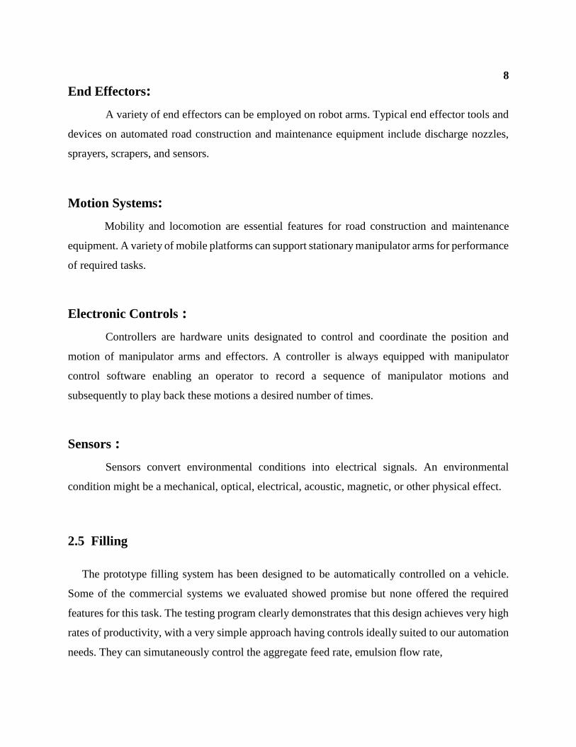
End Effectors:
A variety of end effectors can be employed on robot arms. Typical end effector tools and
devices on automated road construction and maintenance equipment include discharge nozzles,
sprayers, scrapers, and sensors.
Motion Systems:
Mobility and locomotion are essential features for road construction and maintenance
equipment. A variety of mobile platforms can support stationary manipulator arms for performance
of required tasks.
Electronic Controls :
Controllers are hardware units designated to control and coordinate the position and
motion of manipulator arms and effectors. A controller is always equipped with manipulator
control software enabling an operator to record a sequence of manipulator motions and
subsequently to play back these motions a desired number of times.
Sensors :
Sensors convert environmental conditions into electrical signals. An environmental
condition might be a mechanical, optical, electrical, acoustic, magnetic, or other physical effect.
2.5 Filling
The prototype filling system has been designed to be automatically controlled on a vehicle.
Some of the commercial systems we evaluated showed promise but none offered the required
features for this task. The testing program clearly demonstrates that this design achieves very high
rates of productivity, with a very simple approach having controls ideally suited to our automation
needs. They can simutaneously control the aggregate feed rate, emulsion flow rate,

9
temperature, aggregate coverage, and fill. This is the surest way of achieving the most consistent
patch performance.
2.6 Benefits
The technology developed and applied through this SHRP study will have lasting benefit
to all roadway maintenance authorities and workers by making pothole repair safer for all, with
greater performance and productivity than traditional methods. Given a successful
commercialization program and field testing, production models could start to become available
for the benefit of the pavement maintenance community in 1994. We think that different
configurations would be manufactured to maximize the benefit to state highways, districts, cities,
and private contractors. Every group has special requirements as to size, maneuverability, level of
automation, and material capability. Since the APRV was designed as a modular system, each of
the components could be modified to suit the needs of the end user.
2.7 CONCLUSION
Thus, research was done regarding this project on various sources of literature. The many
methodologies were studied and this information has helped to complete the project successfully.

10
CHAPTER 3
SYSTEM DESIGN
3.1 INTRODUCTION
This Robot is designed,which helps the society in promoting the road safety and to reduce
the difficulties in detecting the pothole and also reduce the usage of human power,and hence saves
the time.
This is done in ensuring perfection in all the aspects such as speed, accuracy, flexibility,
safety, reliability and cost effective during the maintanence and service of the robot. The overall
concept of the system will be explained in this chapter.
3.2 ULTRASONIC SENSOR
An Ultrasonic sensor is a device that can measure the distance to an object by using sound
waves. It measures distance by sending out a sound wave at a specific frequency and listening for
that sound wave to bounce back. By recording the elapsed time between the sound wave being
generated and the sound wave bouncing back, it is possible to calculate the distance between the
sonar sensor and the object.
3.3 DC MOTOR
A DC Motor like we all know is a device that deals in the conversion of Electrical energy
to mechanical energy and this is essentially brought about by two major parts required for
the construction of dc motor, namely.
1) Stator – The static part that houses the field windings and receives the supply and
2) Rotor – The rotating part that brings about the mechanical rotations.

11
Other than that there are several subsidiary parts namely
3) Yoke or casting of dc motor.
4) Magnetic poles of dc motor.
5) Field winding of dc motor.
6) Armature winding of dc motor.
7) Commutator of dc motor.
8) Brushes of dc motor.
All these parts put together configures the total construction of a dc motor, that has been
pictorially represented in the diagram below. Fig.3.1.Construction of DC motor.
Fig.3.1.Construction of DC motor
3.4 ARDUINO ATMEGA-328:
The Arduino Nano is a small, complete, and breadboard-friendly board based on the
ATmega328 (Arduino Nano 3.0) or ATmega168 (Arduino Nano 2.x). It has more or less the same
functionality of the Arduino , but in a different package. It lacks only a DC power jack, and

12
works with a Mini-B USB cable instead of a standard one. Fig. 3.2 Architecture of Arduino
Atmega-328.
Fig. 3.2 Architecture of Arduino Atmega-328
I.)Power :
The Arduino Nano can be powered via the Mini-B USB connection, 6-20V unregulated
external power supply (pin 30), or 5V regulated external power supply (pin 27).
II.)Memory:
The ATmega-168 has 16 KB of flash memory for storing code (of which 2 KB is used for

13
bootloader); the ATmega328 has 32 KB, (also with 2 KB used for the bootloader). TheATmega-
168 has 1 KB of SRAM and 512 bytes of EEPROM (which can be read and written with the
EEPROM library); the ATmega328 has 2 KB of SRAM and 1 KB of EEPROM.
III.)Input and Output:
Each of the 14 digital pins on the Nano can be used as an input or output, using pinMode(),
digitalWrite(), and digitalRead() functions. They operate at 5 volts. Each pin can provide or receive
a maximum of 40 mA and has an internal pull-up resistor (disconnected by default) of 20-50
kOhms. In addition, some pins have specialized functions:
Serial:
0 (RX) and 1 (TX). Used to receive (RX) and transmit (TX) TTL serial data. These pins
are connected to the corresponding pins of the FTDI USB-to-TTL Serial chip.
External Interrupts:
2 and 3. These pins can be configured to trigger an interrupt on a low value, a rising or
falling edge, or a change in value. See the attachInterrupt() function for details.
PWM:
3, 5, 6, 9, 10, and 11. Provide 8-bit PWM output with the analogWrite() function.
SPI:
10 (SS), 11 (MOSI), 12 (MISO), 13 (SCK). These pins support SPI communication, which,
although provided by the underlying hardware, is not currently included in the Arduino language.
LED:
13. There is a built-in LED connected to digital pin 13. When the pin is HIGH value, the
LED is on, when the pin is LOW, it's off. The Nano has 8 analog inputs, each of which provide 10
bits of resolution (i.e. 1024 different values). By default they measure from ground to 5 volts,
though is it possible to change the upper end of their range using the analogReference() function.

14
3.5 HUMAN SAFETY
In any automated process human safety holds the first priority. In this process the robot is
monitored by a well equipped skilled person. This prevents the damage to the other humans on the
road. Since the Ultrasonic sensor is fixed on the front of the robot,if any obstacles is detected it
immediately stops the movement of the robot.
3.6 CONCLUSION
The various functionalities and principles used in the Robot have been explained. The
entire working of the Robot has been described. Further details will be seen in the following
chapters.

15
CHAPTER 4
DESIGN CALCULATIONS
4.1 INTRODUCTION
This chapter will include the mechanical design calculations required for the Selection of
Motor used in the project.
4.2 MECHANICAL DESIGN:
The following shows the 3D modeling of the robot. The mechanical Design of the
robot is designed and calculations are made as follows. Fig.4.1. 3D Model of the robot.
Fig.4.1. 3D Model of the robot

16
The weight acting on the shaft will be considered as uniformly distributed load.
Motor Selection:
Total mass of robot = 10Kg
Weight of the robot = 10 * 9.81= 98.1N
Weight acting per shaft = 98.1/4 = 24.5 N
Length of wheel shaft =60 mm
T=(𝜋
16) ∗ 𝜏 ∗ 𝑑3
T=F * R
F=𝜇 ∗ 𝑅 ∗ 𝑁
= 0.7*24.5 = 17.15N
So, T=17.15 * 0.5 = 8.575 Nm
Take velocity = 0.1 m/s
Angular velocity = 𝑣
𝑟 = 0.1/0.05 = 2 rad/s
P= T * W = 8.515 * 2 =17.15W
W = 2𝜋𝑁
60
N = (2*60)/2π =19.098 rpm
Finding diameter of shaft:
Te = √𝑇2 +𝑀2
= 6.1 Nm
6.1= 𝜋
16∗ (250 ∗ 106) ∗ 𝐷3
D = 4.99 * 10-3 m
D using Normal torque = 4.968 * 10-3 m
D using equivalent torque = 4.99 * 10-3 m

17
4.3 CONCLUSION
Thus, the design calculations for the selection of motor were done. These calculations were
done keeping in mind the dimensional restrictions for this project, along with economic views.
The values are well within the limit and the design is safe and accurate.

18
CHAPTER 5
2D AND 3D DIAGRAM OF ROBOT
5.1 INTRODUCTION
This chapter consists of the complete2D and 3D diagram of our project.
5.2 2D AND 3D SETUP
The full view and the 3D design of this project is shown below. Fig.5.1.full view of our
robot
Fig.5.1.full view of our robot

19 The following shows the Part Diagram of the outer mechanical box in the robot Fig.5.2.Part
diagram
Fig.5.2. Part diagram
The following shows the sectional view of the pipe that is used to discharge the concrete. Fig.5.3.
Sectional view of the concrete discharge pipe.
Fig.5.3. Sectional view of the concrete discharge pipe

20
The 2D CAM model of the part is shown as follows in the Fig.5.3. 2D CAM model
Fig.5.3. 2D CAM model

5.3 CONCLUSION
Thus, the part drawing was done using Solid Works modeling software. Based on this
design, the design calculations were done and the machine is kept within these dimensions. The
complete layout of the system is also shown.

21
CHAPTER 6
PROCESS SHEET
6.1 INTRODUCTION
The prime motive of the ‘PROCESS SHEET’ chapter is to provide the fine details about
the components being used, their material and quantity of each component involved in the
project. It also illustrates the processing steps to complete the project.
6.2 COMPONENT SPECIFICATIONS
6.2.1 ARDUINO ATMEGA-328
.The following Table 6.1 General Specifications Arduino Atmega-328 shows the
component specifications were done in this project.
Parameter Value
Operating voltage 5 V
Input voltage 7-12 V
Digital I/O Pins 14(of which 6 provide PWM output)
Analog input pins 8
Memory Flash memory(16KB OR 32KB)
Clock speed 16 MHz
Dimensions 0.73 X 1.70
Table 6.1 General Specifications Arduino Atmega-328

22
6.2.2. DC MOTOR SPECIFICATIONS
The motor Specifications are shown in the Table 6.2 Specifications of DC Motor.
PARAMETER VALUE
Voltage 12V
Speed 30rpm
Current 1 amps
Weight Able to lift 5kg
No of motor 2
Table 6.2 Specifications of DC Motor
6.3 CONCLUSION
Thus the process sheet has been illustrated by tabulating all the process took place during
the design and fabrication of Pothole detection and levelling robot. The tables also contain the
details about the controller used along with their dimensions.

23
CHAPTER 7
PROGRAMMING CONCEPTS
7.1 INTRODUCTION
For the detection of the pothole and to stop the robot automatically when the pothole is
detected, programming is done using C language in Arduino portal.
7.2 ARDUINO PROGRAMMING
//ultrasonic sensor
int tr=2;
int ec=3;
//motor
int a=4;//left motor
int a2=5;
int b1=6;//right motor
int b2=7;
int c1=8;//sweeper
int c2=9;
float d;
void setup() {
pinMode (2,OUTPUT);
pinMode (4,OUTPUT);
pinMode (5,OUTPUT);
pinMode (6,OUTPUT);
pinMode (7,OUTPUT);
pinMode (8,OUTPUT);
pinMode (9,OUTPUT);
Serial.begin(9600);

24
}
Void loop() {
If (dist()>6)
{
Motor(0,0);
Sweep():
}
7.3 CONCLUSION
Thus the control of the Robot and the levelling operations programming is done in
Arduino portal using basic C language.

25
CHAPTER 8
COST OF THE PROJECT
8.1 INTRODUCTION:
This chapter lists the approximate cost of various components used in the project.
8.2 ESTIMATION TABLE:
The following table shows the Cost estimation of this project TABLE 8.1 Cost
Estimation
S.NO COMPONENTS QUANTITY COST
1 Arduino Atmega-
328
1 220
2 DC Motor 2 900
3 Ultrasonic sensor 1 150
4 Wheel 4 280
6 Metal body Fully 1000
7 Additional cost - 500
TOTAL 3050
TABLE 8.1 Cost Estimation

2
6
8.3 CONCLUSION:
The components were chosen with cost as a parameter to optimize the
development of the system.

27
CHAPTER 9
CONCLUSION
9.1 INTRODUCTION
Therefore our Semi Automated Robot, helps the society in promoting the road safety and
to reduce the difficulties in detecting the pothole and also reduce the usage of human power,and
hence saves the time.Therefore by filling the pothole accidents which occur on the road may be
reduced.
9.2 CONCLUSION
The project is successfully completed and tested. All the specified requirements were
fulfilled upon completion the project.

28
REFERENCES
[1] “Automation and robotics for road construction and maintenance”,by miroslaw Skibniewski
and chris Hendrickson.
[2] Herbsman, Z., and Ellis, R. (1988). “Potential application of robotics in highway construction."
Proc, 5th Int. Symp. on Robotics in Constr., Japan Industrial Robot Association, Tokyo, Japan,
June, 299-308.
[3] “Fabrication and Testing of Automated Pothole patching machine” , by James.R.Bhlaha.
[4] Kahane B. and Rosenfeld, y.(2004).Real-time “Sense and Act” operation for construction
robots, Automation in Construction.
[5] Shohet, I.M. and Rosenfeld, Y.(1997). Robotic mapping of building interior-precision analysis,
Automation in Construction.
.
[6] Hyeun-Seok Choia, Chang-Soo Hana, Kye-young Leeb and Sang-heon Leeb, (August 2005),
Development of hybrid robot for construction works with pneumatic actuator, Automation in
Construction, Volume 14, Issue 4, 452-459
[7] A.T.P. and Chan, W.L. (2002). LAN-basedbuilding maintenance and surveillance robot,
Automation in Construction, 11, 6 , 619-627.
[8] Werfel, J., Bar-Yam, Y. and Nagpal, R. (2005).Building Patterned Structures with Robot
Swarms,Computer Science and Artificial IntelligenceLaboratory, Technical Report,
MassachusettsInstitute of technology, Cambridge, USA.
[9] Kalay, Y.E. and Skibniewski, M.J. Automation in Construction journal,
www.iaarc.org/_old/frame/publish/autcon.htm.