Embed Size (px)
Citation preview
Review ArticleVolume 8 Issue 1 - August 2017DOI: 10.19080/CTBEB.2017.08.555729
Curr Trends Biomedical Eng & Biosci Copyright © All rights are reserved by Chukwuedozie N Ezema
Design and Implementation of Microcontroller Based Logic Gate Tester
Chukwuedozie N Ezema1*, Chinazam C. Ezema1 and Ernest O Nonum2
1Nnamdi Azikiwe, University Awka, Nigeria2Novena University, Nigeria
Submission: August 08, 2017; Published: August 29, 2017
*Corresponding author: Chukwuedozie N Ezema, Nnamdi Azikiwe, University Awka, Anambra State, Nigeria, Email:
IntroductionThe Logic gate tester is used to test integrated circuit logic
ICs. We don’t need to rig up different kinds of circuits for different kind of logic ICs, each time we need to test them. The chip tester verifies the functionality and timing of some variety of 7400 series logic gate integrated circuits. Students taking Digital Logic
Design Lab, Use these chips often in their laboratory. The IC to be tested should be placed on the ZIF socket and the Microcontroller prompts the user to enter the IC number of the chip to be tested. After entering it the microcontroller will check the IC as per the truth table of the IC which is stored in its ROM. It will check each and every pin of the IC and produce the Output detail. Like “Gate 1 is good”, “Gate is bad”, “Counter 1 is good” etc
Curr Trends Biomedical Eng & Biosci 8(1): CTBEB.MS.ID.555729 (2017) 0016
Abstract
In electronics, testing tools is a major part when it comes to laboratory work. It’s a part of everyday activity to use one or several too while working on electrical system. No workman can do without testing tools. It is of great importance on practical basis. Thus the aim of this research is to build a Logic tester capable of testing most 74 series logic gates integrated circuits using a Microcontroller (AT89C51). This project is basically designed test or determines the condition of the gates in a logic gate IC by simulating its characteristics using the truth table of the particular IC. Different design approaches were compared and finally one approach was implemented. Each individual module was designed separately. After successful simulation and testing, they were put together to create the finalized version.
Keywords: Logic gate tester; Digital primer; Regulator; Microcontroller; Integrated circuits (ICs)
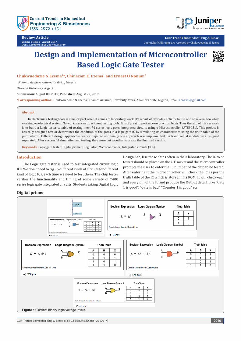
Digital primer
Figure 1: Distinct binary logic voltage levels.
Current Trends in Biomedical Engineering & Biosciences
How to cite this article: Chukwuedozie N E, Chinazam C. Ezema, Ernest O N. Design and Implementation of Microcontroller Based Logic Gate Tester. Curr Trends Biomedical Eng & Biosci. 2017; 8(1): 555729. DOI: 10.19080/CTBEB.2017.08.555729.0017
Two voltage levels can be represented as the two digits 0 and 1. Signals in digital electronics have two distinct voltage levels with built-in tolerances for variations in the voltage. A valid digital signal should be within either of the two shaded areas as shown in (Figure 1).
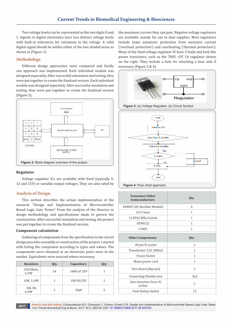
MethodologyDifferent design approaches were compared and finally
one approach was implemented. Each individual module was designed separately. After successful simulation and testing, they were put together to create the finalized version. Each individual module was designed separately. After successful simulation and testing, they were put together to create the finalized version (Figure 2).
Figure 2: Block diagram overview of the project.
RegulatorVoltage regulator ICs are available with fixed (typically 5,
12 and 15V) or variable output voltages. They are also rated by
the maximum current they can pass. Negative voltage regulators are available, mainly for use in dual supplies. Most regulators include some automatic protection from excessive current (‘overload protection’) and overheating (‘thermal protection’). Many of the fixed voltage regulator IC have 3 leads and look like power transistors, such as the 7805 +5V 1A regulator shown on the right. They include a hole for attaching a heat sink if necessary (Figure 3 & 4).
Figure 3: (a) Voltage Regulator. (b) Circuit Symbol.
Figure 4: Flow chart approach.
Analysis of DesignThis section describes the actual implementation of the
research “Design and Implementation of Microcontroller Based Logic Gate Tester.” From the analysis of the theories in design methodology and specifications made to govern the construction. After successful simulation and testing, the project was put together to create the finalized version.
Component calculationGathering of components from the specification in the circuit
design precedes assembly or construction of the project. I started with listing the component according to types and values. The components were obtained at an electronic parts store in the market. Equivalents were sourced where necessary.
Resistors: Qty. Capacitors: Qty.
220 Ohms, 1/4W 14 1000 uF 25V 1
10K, 1/4W 1 100 Uf/25V 1
10k VR, 1/4W 1 33pF 2
Transistor/Other Semiconductors: Qty.
1N4007 (Or Rectifier Module) 4
16*2 lines 1
11.0592 MHz Crystal 1
AT89C52 1
L7805 1
Other Components: Qty.
40 pin IC socket 1
Transformer 12V, 500mA 1
Power Switch 1
Mains power cord 1
Vero Board (Big size) 1
Connecting Flexible wire 3yd
Zero Insertion Force IC socket 1
Push Button Switch 12
Current Trends in Biomedical Engineering & Biosciences
How to cite this article: Chukwuedozie N E, Chinazam C. Ezema, Ernest O N. Design and Implementation of Microcontroller Based Logic Gate Tester. Curr Trends Biomedical Eng & Biosci. 2017; 8(1): 555729. DOI: 10.19080/CTBEB.2017.08.555729.0018
Hardware implementationThis involves the actual construction, which is the hard
wiring of the circuit already prototyped. This consists of thin copper strips on one side and plain insulator board on the other side punched with hole at 0.1- inch matrix interval. Components are mounted on the plain side and soldered on the copper side. The copper strip runs from left to right and all components soldered on the strip are automatically joined together; where that is not required the strip is cut at appropriate point with drill or sharp object. All the components were mounted and soldered taking care that the transistors, electrolytic capacitors, diodes and the regulator were mounted the correct way round. The LED was connected with flexible wires, so that they may be mounted on the case. While soldering the solder blobs should not touch the adjacent tracks otherwise there will be short circuit. Finally the IC should be mounted on the IC socket and tracks under the socket were cut to separate the pins.
Input interface wiring diagram: The circuit arrangement below shows the input keypad interface implementation wiring diagram (Figure 5).
Figure 5: Typical (4*3) matrix keypad arrangement.
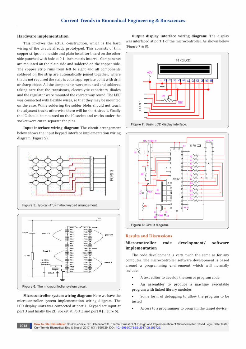
Figure 6: The microcontroller system circuit.
Microcontroller system wiring diagram: Here we have the microcontroller system implementation wiring diagram. The LCD display units was connected at port 1, Keypad set input at port 3 and finally the ZIF socket at Port 2 and port 0 (Figure 6).
Output display interface wiring diagram: The display was interfaced at port 1 of the microcontroller. As shown below (Figure 7 & 8).
Figure 7: Basic LCD display interface.
Figure 8: Circuit diagram.
Results and DiscussionsMicrocontroller code development/ software implementation
The code development is very much the same as for any computer. The microcontroller software development is based around a programming environment which will normally include:
• A text editor to develop the source program code
• An assembler to produce a machine executable program with linked library modules
• Some form of debugging to allow the program to be tested
• Access to a programmer to program the target device.

Current Trends in Biomedical Engineering & Biosciences
How to cite this article: Chukwuedozie N E, Chinazam C. Ezema, Ernest O N. Design and Implementation of Microcontroller Based Logic Gate Tester. Curr Trends Biomedical Eng & Biosci. 2017; 8(1): 555729. DOI: 10.19080/CTBEB.2017.08.555729.0019
• The job of the assembler is to convert the source code produced by the programmer into an object code file. It works by replacing each line of assembly instruction code with the corresponding machine code instruction that will be executed on the target microcontroller.
The object code file cannot be executed on the target microcontroller. It needs to be passed through a program called a linker. The job of the linker is to take the object file produced by the assembler and link it with standard library modules (that have already been pre-assembled into object files) to produce a complete working executable file that can be loaded into the memory of the microcontroller. Sometimes the assembler and linker are combined into one program so that assembling a source program automatically links it as well. This is the case with the 8051 Assembler.
Figure 9: Stages in the production of a program.
Figure 9, below shows the different stages in the production of a program. Note that the only stage that requires a lot of user input is the initial production of the user source code file. The rest of the program production involves using the Assembler and Linker tools.
• ‘Filename’ is the name of the program that the user is developing, thus the output of the Editor is the source file ‘filename.asm’.
• The output of the Assembler is the object file ‘filename.obj’.
• The Linker links the ‘filename.obj’ with any Library object files that the program might use. It will also link any user object files that the user might want to include.
The Linker output is the executable file to run on the target system.
A program called a Loader or a microcontroller programmer takes your executable file from the hard disk and loads it onto the target microcontroller.
Complete system testWhen the system is switched on, the microcontroller
initializes the LCD, and writes the name of the project on screen. Then it prompts the user to input, the IC number. Once that is done the microcontroller verifies the functionality of the logic
gate making reference to the truth table. If the gate is OK it will signal Gates OK if gated is bad it will signal Gate bad. If the Logic gate IC is not in the data base it will also display that on the screen. The part number of the IC entered must be maximum 5 digits and will have the suffix (74xxx). The cancel button could be pressed to clear LCD screen for another data entry [1-8].
ConclusionThe research, “Design and Implementation of Microcontroller
based Logic gate tester”, proved to be a very interesting research to embark on, however whenever there is a task to perform, there could be problems likely to come up. In the course of this research the integrated logic gate tester was used to test logic gate Integrated Circuits (ICs). We can easily test any digital IC using this kind of an IC tester. For testing an IC, we need to use different hardware circuits for different ICs; like we need a particular kind of tester for testing each individual logic gate ICs. The task of accommodating each logic IC routine is enormous mistakes are prone to happen. So there is continues debugging of the code and hardware matching to the system. To test a particular digital IC, one needs to insert the IC into the IC socket and enter the IC number using the keyboard and then press the “ENTER” key. The IC number gets displayed on LCD unit. If the IC being tested is a logic gate, then each of the gates will be tested for functionality.
References1. Kopelman PG (2000) Obesity as a medical problem. Nature 404(6778):
635-643.
2. Flegal KM, Graubard BI, Williamson DF, Gail MH (2007) Cause-specific excess deaths associated with underweight, overweight, and obesity. JAMA 298(17): 2028-20373.
3. Ogden CL, Carroll MD, Flegal KM (2008) High body mass index for age among US children and adolescents, 2003-2006. JAMA 299(20): 2401-2405.
4. Garver WS, Newman SB, Gonzales-Pacheco DM, Castillo JJ, Jelinek D, et al. (2013) The genetics of childhood obesity and interaction with dietary macronutrients. Genes Nutr 8(3): 271-287.
5. Ogden CL, Carroll MD, Kit BK, Flegal KM (2012) Prevalence of obesity and trends in body mass index among US children and adolescents, 1999-2010. JAMA 307(5): 483-490.
6. www. samhsa.gov/oas/nhsda/trean05.htm
7. SAMHSA (Substance Abuse and Mental Health Services Administration) (2002). Results from the 2001 National Household Survey on Drug Abuse: Volume I. Summary of national findings. Office of Applied Studies, NHSDA Series H-17, DHHS Publication No. SMA 02-3758, Rockville, MD: SAMHSA.
8. Frank DA, Augustyn M, Knight WG, Pell T, Zuckerman B (2001) Growth, development, and behavior in early childhood following prenatal cocaine exposure: a systematic review. JAMA 285(1): 1613-1625.
9. http://www.drugfree.org
10. http://oas.samhsa.gov/nsduh/2k6nsduh/2k6Results.pdf
11. http://www.casacolumbia.org/absolutenm/articlefiles/380-under_the_counter_-_diversion.pdf
12. Young JL, Martin PR (2012) Treatment of opioid dependence in the setting of pregnancy. Psychiatr Clin North Am 35(2): 441-460.

Current Trends in Biomedical Engineering & Biosciences
How to cite this article: Chukwuedozie N E, Chinazam C. Ezema, Ernest O N. Design and Implementation of Microcontroller Based Logic Gate Tester. Curr Trends Biomedical Eng & Biosci. 2017; 8(1): 555729. DOI: 10.19080/CTBEB.2017.08.555729.0020
This work is licensed under CreativeCommons Attribution 4.0 LicenseDOI: 10.19080/CTBEB.2017.08.555729
Your next submission with Juniper Publishers will reach you the below assets
• Quality Editorial service• Swift Peer Review• Reprints availability• E-prints Service• Manuscript Podcast for convenient understanding• Global attainment for your research• Manuscript accessibility in different formats
( Pdf, E-pub, Full Text, Audio) • Unceasing customer service
Track the below URL for one-step submission https://juniperpublishers.com/online-submission.php
13. Mozurkewich EL, Rayburn WF (2014) Buprenorphine and Methadone for Opioid Addiction During Pregnancy. Obstet Gynecol Clin N Am 41(2): 241-253.
14. Maes HH, Neale MC, Eaves LJ (1997) Genetic and environmental factors in relative body weight and human adiposity. Behavior Genetics 27(4): 325-351.
15. Monteleone P, Tortorella A, Martiadis V, Serritella C, Fuschino A (2004) Opposite changes in the serum brain-derived neurotrophic factor in anorexia nervosa and obesity. Psychosomatic Medicine 66(5): 744-748.
16. El-Gharbawy AH, Adler-Wailes DC, Mirch MC, Theim KR, Ranzenhofer L, et al. (2006) Serum brain-derived neurotrophic factor concentrations in lean and overweight children and adolescents. J Clin Endocrinol Metab 91(9): 3548-3552.
17. Krabbe KS, Nielsen AR, Krogh-Madsen R, Plomgaard P, Rasmussen P, et al. (2007) Brain derived neurotrophic factor (BDNF) and type 2 diabetes. Diabetologia 50(2): 431-438.
18. Yeo GS, Connie Hung CC, Rochford J, Keogh J, Gray J, et al. (2004) A de novo mutation affecting human TrkB associated with severe obesity and developmental delay. Nature Neuroscience 7(11): 1187-1189.
19. Yu Y, Wang Q, Huang XF (2009) Energy-restricted pair-feeding normalizes low levels of brain-derived neurotrophic factor/tyrosine kinase B mRNA expression in the hippocampus, but not ventromedial hypothalamic nucleus, in diet-induced obese mice,” Neuroscience 160(2): 295-306.
20. Unger TJ, Calderon GA, Bradley LC, Sena-Esteves M, Rios M (2007) Selective deletion of Bdnf in the ventromedial and dorsomedial hypothalamus of adult mice results in hyperphagic behavior and obesity. J Neurosci 27: 14265-14274.
21. Lyons WE, Mamounas LA, Ricaurte GA, Coppola V, Reid SW, et al. (1999) Brain-derived neurotrophic factor-deficient mice develop aggressiveness and hyperphagia in conjunction with brain serotonergic abnormalities. Proc Natl Acad Sci U S A 96(26): 15239-15244.
22. Rios M, Fan G, Fekete C, Kelly J, Bates B, et al. (2005) Conditional deletion of brain-derived neurotrophic factor in the postnatal brain leads to obesity and hyperactivity. Molecular Endocrinology 15(10): 1748-1757.
23. Kernie SG, Liebl DJ, Parada LF (2000) BDNF regulates eating behavior and locomotor activity in mice. EMBO J 19(6): 1290-1300.
24. Fox EA, Byerly MS (2004) A mechanism underlying mature-onset obesity: evidence from the hyperphagic phenotype of brain-derived neurotrophic factor mutants. Am J Physiol Regul Integr Comp Physiol 286(6): R994-1004.
25. Gray J, Yeo GS, Cox JJ, Morton J, Adlam AL, et al. (2006) Hyperphagia, severe obesity, impaired cognitive function, and hyperactivity associated with functional loss of one copy of the brain-derived neurotrophic factor (BDNF) gene. Diabetes 55(12): 3366-3371.
26. Hyman SE (2005) Addiction: a disease of learning and memory. Am J Psychiatry 162(8): 1414-22.
27. Araki S, Yamamoto Y, Dobashi K, Asayama K, Kusuhara K (2014) Decreased plasma levels of brain-derived neurotrophic factor and its relationship with obesity and birth weight in obese Japanese children. Obes Res Clin Pract 8(1): e63-e69.
28. Miller CA, Campbell SL, Sweatt JD (2008) DNA methylation and histone acetylation work in concert to regulate memory formation and synaptic plasticity. Neurobiol Learn Mem 89(4): 599-603.
29. Konijnenberg C, Melinder A (2011) Prenatal exposure to methadoneand buprenorphine: a review of the potential effects on cognitive development. Child Neuropsychol 17(5): 1-25.
30. Che Y, Sun H, Tan H, Peng Y, Zeng T, et al. (2005) The effect ofprenatal morphine exposure on memory consolidation in thechick. Neurosci Lett 380(3): 300-304.
31. Yang SN, Liu CA, Chung MY, Huang HC, Yeh GC, et al. (2006) Alterations of postsynapticdensity proteins in the hippocampus of rat offspring from themorphine-addicted mother: beneficial effect of dextromethorphan. Hippocampus 16(6): 521-530.
32. Nasiraei-Moghadam S, Kazeminezhad B, Dargahi L, Ahmadiani A (2010) Maternal oral consumption of morphine increases Bax/Bcl-2 ratio and caspase 3 activity during early neural systemdevelopment in rat embryos. J MolNeurosci 41(1): 156-164.
33. Yang SN, Huang LT, Wang CL, Chen WF, Yang CH, et al. (2003) Prenatal administration ofmorphine decreases CREBSerine-133 phosphorylation and synapticplasticity range mediated by glutamatergic transmission inthe hippocampal CA1 area of cognitive-deficient rat offspring. Hippocampus 13(8): 915-921.