Embed Size (px)
Citation preview
International Journal of Science and Research (IJSR) ISSN (Online): 2319-7064
Index Copernicus Value (2013): 6.14 | Impact Factor (2013): 4.438
Volume 4 Issue 5, May 2015
www.ijsr.net Licensed Under Creative Commons Attribution CC BY
Design and Implementation of Non-Isolated Three-
Port DC/DC Converter for Stand-Alone Renewable
Power System Applications
Archana1, Nalina Kumari
2
1PG Student (power Electronics), Department of EEE, The Oxford College of Engineering, Bangalore, India
2Assistant Professor, Department of EEE, The Oxford College of Engineering, Bangalore, India
Abstract: DC-DC Converters are those devices which have the ability to change one level of direct voltage/ direct current to that of
another level. Non-Isolated DC/DC three-port converters intermeddling the input source that is photovoltaic array, storage device like
battery and the load is proposed in Stand-Alone Renewable system applications. In This application PV panel is not being connected to
the grid but instead are used for charging the batteries. Each port is used for specific input or output, and its functions depend on the
port; they are the renewable source, the battery set, and the output port. Three-Port Converters are bring into existence by introducing a
bidirectional converter into Boost converter. Power flow path either from PV array to the load or from battery to the load is achieved in
this project. Using four regulators accomplishing Maximum Power Point Tracking (MPPT) control of PV array, governs the charging
battery and voltage control of the load. PWM scheme applied to the Three-Port Converter based on power relations among three ports.
DC/DC Converter works in every operation mode and switch between dissimilar mode easily. Three-Port Converter has advantages of
high efficiency, higher flexibility, reliability and lower cost. A proposed system is simulated using MATLAB/SIMULINK environment.
Keywords: PV array, DC/DC converter, Bidirectional converter, MPPT controller.
1. Introduction
Now a day’s world population is increasing rapidly, the
power demand is also increasing frequently. Conventional
energy sources like oil, coal and so on (fossil fuels) are
continuously depleting in the recent years in the universe, it
is necessary to known various choice of energy sources in
order to meet power demands. Hence renewable sources play
an important role in generating power and achieve the load
requirements. Advantages like low maintenance, almost nil
harmful emissions, and renewable energy sources hold virtual
role in satisfying the future load demand.
Applications of renewable energy sources may be different
depending upon whether they are connected to the grid or
not, also known as standalone system. Standalone system is
also known as remote area power supply (RAPS), it is an off-
the-grid electricity system for the locations that are not
connected with an electricity distribution system. Standalone
system includes electricity generation, energy storage and
generation.
The renewable source like solar energy utilization has been
looked upon by many researchers all around the world. It has
been known that solar cell operates at very low efficiency
approximately around 20% and thus a better control
mechanism is required to increase the overall efficiency of
the solar cell. In this field researchers have developed that
are nothing Maximum Power Point Tracking (MPPT)
algorithms [1].
PV array should be the main energy source in standalone
application. Renewable sources like solar, wind are not
regular in nature. Hence storage device like battery is
required for stand-alone power system to improve overall
dynamics of the system. Renewable energy sources have few
disadvantages like fluctuation in output due to weather
conditions, temperature irradiance. To overcome from these
drawbacks battery is used as a storage element to improve
dynamic characteristics.
The power management of power converter is required in
order to meet output power. Three-Port DC/DC converter is
best for standalone PV system applications. TPC has
advantages of less component count, lower cost higher
reliability and fewer conversion stages [2]-[4]. Due to
considerable advantages of the TPC, a variety of topologies
have been proposed in different fields, like hybrid electric
vehicles [5]-[8]. PV system with battery backup [9]-[12].
2. Photovoltaic system
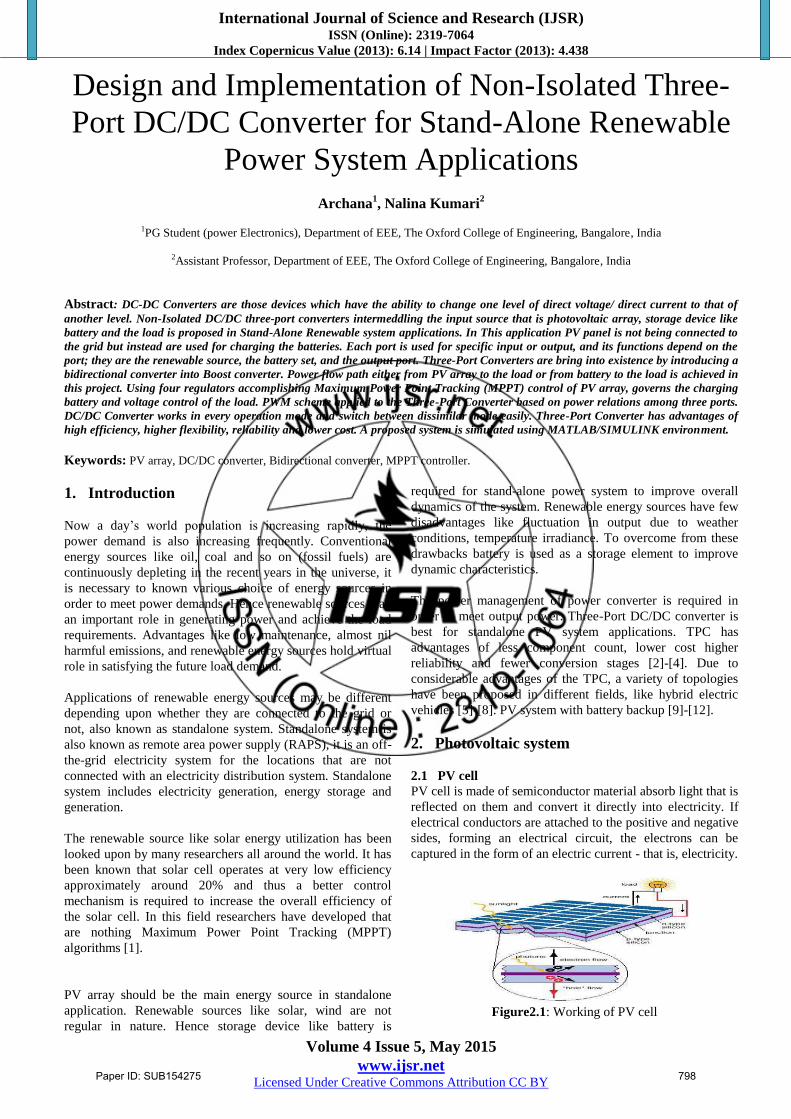
2.1 PV cell
PV cell is made of semiconductor material absorb light that is
reflected on them and convert it directly into electricity. If
electrical conductors are attached to the positive and negative
sides, forming an electrical circuit, the electrons can be
captured in the form of an electric current - that is, electricity.
Figure2.1: Working of PV cell
Paper ID: SUB154275 798
International Journal of Science and Research (IJSR) ISSN (Online): 2319-7064
Index Copernicus Value (2013): 6.14 | Impact Factor (2013): 4.438
Volume 4 Issue 5, May 2015
www.ijsr.net Licensed Under Creative Commons Attribution CC BY
2.1 PV module
Due to the low voltage generated in a PV cell (around 0.5V),
several PV cells are connected in series (for high voltage)
and in parallel (for high current) to form a PV module for
desired output. Separate diodes may be needed to avoid
reverse currents, in case of partial or total shading, and at
night.
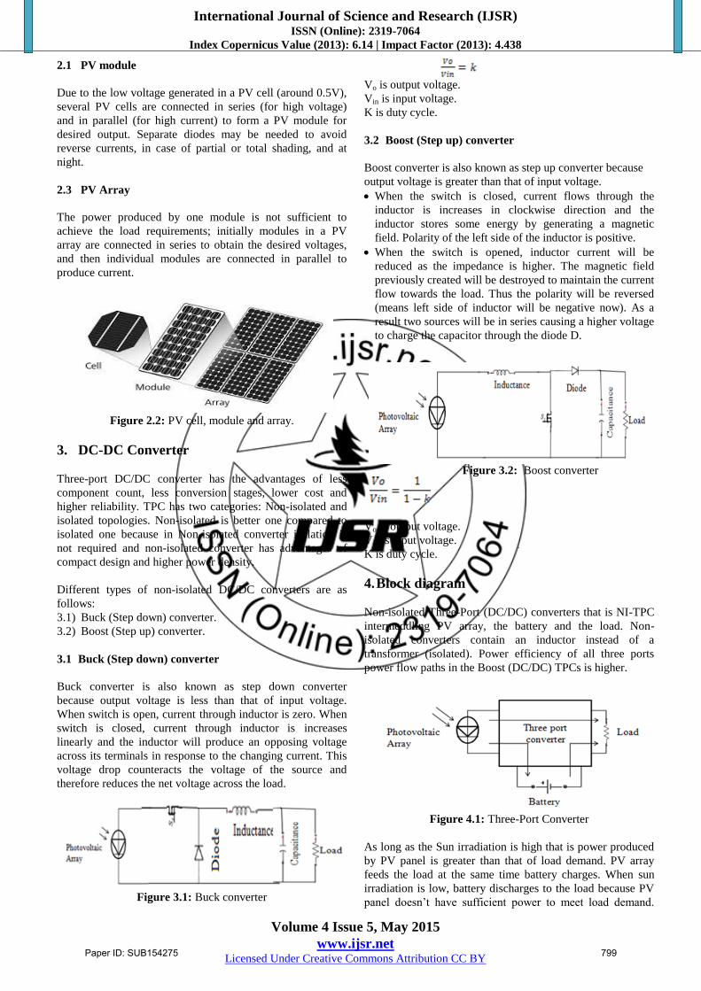
2.3 PV Array
The power produced by one module is not sufficient to
achieve the load requirements; initially modules in a PV
array are connected in series to obtain the desired voltages,
and then individual modules are connected in parallel to
produce current.
Figure 2.2: PV cell, module and array.
3. DC-DC Converter
Three-port DC/DC converter has the advantages of less
component count, less conversion stages, lower cost and
higher reliability. TPC has two categories: Non-isolated and
isolated topologies. Non-isolated is better one compared to
isolated one because in Non-isolated converter isolation is
not required and non-isolated converter has advantages of
compact design and higher power density.
Different types of non-isolated DC/DC converters are as
follows:
3.1) Buck (Step down) converter.
3.2) Boost (Step up) converter.
3.1 Buck (Step down) converter
Buck converter is also known as step down converter
because output voltage is less than that of input voltage.
When switch is open, current through inductor is zero. When
switch is closed, current through inductor is increases
linearly and the inductor will produce an opposing voltage
across its terminals in response to the changing current. This
voltage drop counteracts the voltage of the source and
therefore reduces the net voltage across the load.
Figure 3.1: Buck converter
Vo is output voltage.
Vin is input voltage.
K is duty cycle.
3.2 Boost (Step up) converter
Boost converter is also known as step up converter because
output voltage is greater than that of input voltage.
When the switch is closed, current flows through the
inductor is increases in clockwise direction and the
inductor stores some energy by generating a magnetic
field. Polarity of the left side of the inductor is positive.
When the switch is opened, inductor current will be
reduced as the impedance is higher. The magnetic field
previously created will be destroyed to maintain the current
flow towards the load. Thus the polarity will be reversed
(means left side of inductor will be negative now). As a
result two sources will be in series causing a higher voltage
to charge the capacitor through the diode D.
Figure 3.2: Boost converter
Vo is output voltage.
Vin is input voltage.
K is duty cycle.
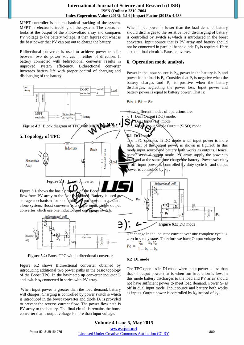
4. Block diagram
Non-isolated Three-Port (DC/DC) converters that is NI-TPC
intermeddling PV array, the battery and the load. Non-
isolated converters contain an inductor instead of a
transformer (isolated). Power efficiency of all three ports
power flow paths in the Boost (DC/DC) TPCs is higher.
Figure 4.1: Three-Port Converter
As long as the Sun irradiation is high that is power produced
by PV panel is greater than that of load demand. PV array
feeds the load at the same time battery charges. When sun
irradiation is low, battery discharges to the load because PV
panel doesn’t have sufficient power to meet load demand.
Paper ID: SUB154275 799
International Journal of Science and Research (IJSR) ISSN (Online): 2319-7064
Index Copernicus Value (2013): 6.14 | Impact Factor (2013): 4.438
Volume 4 Issue 5, May 2015
www.ijsr.net Licensed Under Creative Commons Attribution CC BY
MPPT controller is not mechanical tracking of the system.
MPPT is electronic tracking of the system. The controller
looks at the output of the Photovoltaic array and compares
PV voltage to the battery voltage. It then figures out what is
the best power that PV can put out to charge the battery.
Bidirectional converter is used to achieve power transfer
between two dc power sources in either of direction. If
battery connected with bidirectional converter results in
improved system efficiency. Bidirectional converter
increases battery life with proper control of charging and
discharging of the battery.
Figure 4.2: Block diagram of TPC with MPPT controller.
5. Topology of TPC
Figure 5.1: Boost converter
Figure 5.1 shows the basic property of the Boost TPC. Power
flow from PV array to the load is defined. Battery is used as
storage mechanism for smoothing output power in a stand-
alone system. Boost converter is a single input, single output
converter which use one inductor and one power switch.
Figure 5.2: Boost TPC with bidirectional converter
Figure 5.2 shows Bidirectional converter obtained by
introducing additional two power paths in the basic topology
of the Boost TPC. In the basic step up converter inductor L
and switch s1 connected in series with PV array.
When input power is greater than the load demand, battery
will charges. Charging is controlled by power switch s2 which
is introduced in the boost converter and diode D2 is provided
to prevent the reverse current flow. The power flow path is
PV array to the battery. The final circuit is remains the boost
converter that is output voltage is more than input voltage.
When input power is lower than the load demand, battery
should discharges to the resistive load, discharging of battery
is controlled by switch s3 which is introduced in the boost
converter. Input source that is PV array and battery should
not be connected in parallel hence diode D3 is required. Here
also the final circuit is Boost converter.
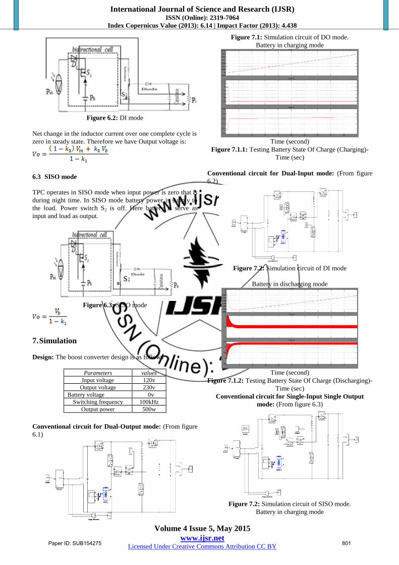
6. Operation mode analysis
Power in the input source is Pin, power in the battery is Pb and
power in the load is Po. Consider that Pb is negative when the
battery charges and Pb is positive when the battery
discharges, neglecting the power loss. Input power and
battery power is equal to battery power. That is:
Three different modes of operations are:
6.1 Dual Output (DO) mode.
6.2 Dual Input (DI) mode.
6.3 Single Input Single Output (SISO) mode.
6.1 DO mode
The TPC operates in DO mode when input power is more
than that of the output power is shown in figure8. In this
mode input source and battery both works as outputs. Hence,
named as dual-output mode. PV array supply the power to
load and at the same time charge the battery. Power switch s3
is off, input power is controlled by duty cycle k1 and output
power is controlled by k2 .
Figure 6.1: DO mode
Net change in the inductor current over one complete cycle is
zero in steady state. Therefore we have Output voltage is:
6.2 DI mode
The TPC operates in DI mode when input power is less than
that of output power that is when sun irradiation is low. In
this mode battery discharges to the load and PV array should
not have sufficient power to meet load demand. Power S2 is
off in dual input mode. Input source and battery both works
as inputs. Output power is controlled by k3 instead of k2 .
Paper ID: SUB154275 800
International Journal of Science and Research (IJSR) ISSN (Online): 2319-7064
Index Copernicus Value (2013): 6.14 | Impact Factor (2013): 4.438
Volume 4 Issue 5, May 2015
www.ijsr.net Licensed Under Creative Commons Attribution CC BY
Figure 6.2: DI mode
Net change in the inductor current over one complete cycle is
zero in steady state. Therefore we have Output voltage is:
6.3 SISO mode
TPC operates in SISO mode when input power is zero that is
during night time. In SISO mode battery power is supply to
the load. Power switch S2 is off. Here battery is serve as
input and load as output.
Figure 6.3: SISO mode
7. Simulation
Design: The boost converter design is as follows
Parameters values
Input voltage 120v
Output voltage 230v
Battery voltage 0v
Switching frequency 100kHz
Output power 500w
Conventional circuit for Dual-Output mode: (From figure
6.1)
Figure 7.1: Simulation circuit of DO mode.
Battery in charging mode
Time (second)
Figure 7.1.1: Testing Battery State Of Charge (Charging)-
Time (sec)
Conventional circuit for Dual-Input mode: (From figure
6.2)
Figure 7.2: Simulation circuit of DI mode
Battery in discharging mode
Time (second)
Figure 7.1.2: Testing Battery State Of Charge (Discharging)-
Time (sec)
Conventional circuit for Single-Input Single Output
mode: (From figure 6.3)
Figure 7.2: Simulation circuit of SISO mode.
Battery in charging mode
Paper ID: SUB154275 801
International Journal of Science and Research (IJSR) ISSN (Online): 2319-7064
Index Copernicus Value (2013): 6.14 | Impact Factor (2013): 4.438
Volume 4 Issue 5, May 2015
www.ijsr.net Licensed Under Creative Commons Attribution CC BY
Time (second)
Figure 7.1.3: Testing Battery State Of Charge (Charging)-
Time (sec)
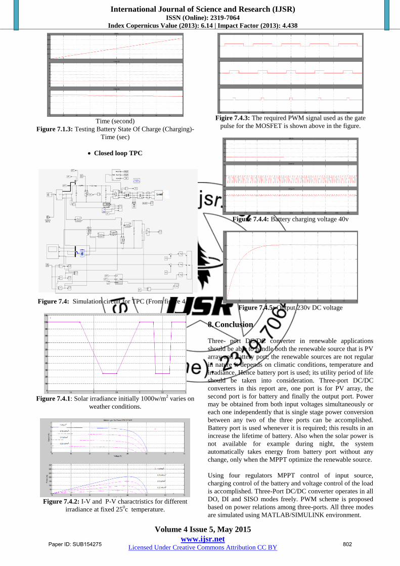
Closed loop TPC
Figure 7.4: Simulation circuit for TPC (From figure 4.2)
Figure 7.4.1: Solar irradiance initially 1000w/m
2 varies on
weather conditions.
Figure 7.4.2: I-V and P-V charactristics for different
irradiance at fixed 250c temperature.
Figire 7.4.3: The required PWM signal used as the gate
pulse for the MOSFET is shown above in the figure.
Figure 7.4.4: Battery charging voltage 40v
Figure 7.4.5: Output 230v DC voltage
8. Conclusion
Three- port DC/DC converter in renewable applications
should be able to handle both the renewable source that is PV
array and battery port; the renewable sources are not regular
in nature it depends on climatic conditions, temperature and
irradiance. Hence battery port is used; its utility period of life
should be taken into consideration. Three-port DC/DC
converters in this report are, one port is for PV array, the
second port is for battery and finally the output port. Power
may be obtained from both input voltages simultaneously or
each one independently that is single stage power conversion
between any two of the three ports can be accomplished.
Battery port is used whenever it is required; this results in an
increase the lifetime of battery. Also when the solar power is
not available for example during night, the system
automatically takes energy from battery port without any
change, only when the MPPT optimize the renewable source.
Using four regulators MPPT control of input source,
charging control of the battery and voltage control of the load
is accomplished. Three-Port DC/DC converter operates in all
DO, DI and SISO modes freely. PWM scheme is proposed
based on power relations among three-ports. All three modes
are simulated using MATLAB/SIMULINK environment.
Paper ID: SUB154275 802
International Journal of Science and Research (IJSR) ISSN (Online): 2319-7064
Index Copernicus Value (2013): 6.14 | Impact Factor (2013): 4.438
Volume 4 Issue 5, May 2015
www.ijsr.net Licensed Under Creative Commons Attribution CC BY
References
[1] Mummadi Veerachary, "Control of TI-SEPIC Converter
for Optimal Utilization of PV Power", IICPE, 2010 New
Delhi.
[2] W. Jiang and B. Fahimi, “Multi-port power electric
interface for renewable energy sources,” in Proc. IEEE
2009 Appl. Power Electron. Conf., pp. 347-352.
[3] H. Tao. J. L. Duarte, Hendrix, M.A.M., “Multiport
converters for hybrid power sources,” in IEEE Proc.
PESC, USA, 2008.
[4] G. Su and L. Tang, “A reduced-part, triple-voltage DC-
DC converter for EV-HEV power management,” IEEE
Trans. Power Electron., vol. 24, no. 10, pp. 2406-3410,
Oct. 2009.
[5] Gui-Jia Su, Lixin Tang, “A multiphase, modular,
bidirectional, triple voltage DC-DC converter for hybrid
and fuel cell vehicle power system, ” IEEE Trans. on
Power Electronics, vol. 23, no. 6, pp. 3035- 3046, 2008.
[6] G. Gamboa, C. Hamilton, R. Kerley, “Control strategy of
a multi- port, grid connected direct DC PV charging
station for plug-in electric vehicles ,” in proc. IEEE
Energy Conversion Congress & Expo, Atlanta, USA,
2010, pp. 1173-1177.
[7] Chuanhong Zhao, Simon D. Round, Johann W., “An
isolated three-port bidirectional DC-DC converter with
decoupled power flow management,” IEEE Trans. on
Power Electronics, vol. 23, no. 5, pp. 2443 -2453, 2008.
[8] Haimin Tao, J. L. Duarte, Marcel A. M., “Three-port
triple-half-bridge bidirectional converter with zero-
voltage switching,” IEEE Trans. On power Electronics,
vol. 23, no. 2, pp. 782-792, 2008.
[9] H. Tao, A. Kotsopoulos, J. Duarte, and M. Hendrix,
“Transformer coupled multiport ZVS bidirectional dc-dc
converter with wide input range,” IEEE Trans. Power
Electron., vol. 23, no. 2, pp. 771-781, Mar. 2008
[10] Zhan Wang, Hui Li, “Integrated MPPT and bidirectional
battery charger for PV application using one multiphase
interleaved three-port DC-DC converter,” in Proc. IEEE
APEC 2011, USA, pp. 295-300.
[11] Hongfei Wu, Kai Sun, Zihu Zhou, Yan Xing, “An
integrated four-port full-bridge converter with DMPPT
for renewable power system,” in PEDG, 2012 3rd IEEE
International Symposium on, 2012, pp. 895- 900.
[12] Hongfei Wu, Runruo Chen, Junjun Zhang, Yan Xing, “A
family of three-port half-bridge converters for a stand-
alone renewable power system,” IEEE Trans. on Power
Electronics, vol. 26, no.9, pp. 2697-2706, 2011.
Author Profile Rachana received the B.E degree in Electrical and
Electronics Engineering from Guru Nanak Dev
Engineering College Bidar in 2011 affiliated to VTU
Belgum, and pursuing M.Tech in Power Electronics
from The Oxford College of Engineering, Bangalore from 2013 to
2015 affiliated to VTU Belgum.
Paper ID: SUB154275 803