Embed Size (px)
DESCRIPTION
Notes on SMPS
Citation preview
SMPS - Switch Mode Power SupplyDC Power Supply
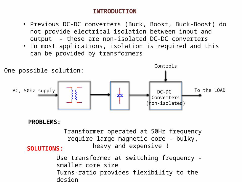
• Previous DC-DC converters (Buck, Boost, Buck-Boost) do not provide electrical isolation between input and output - these are non-isolated DC-DC converters
• In most applications, isolation is required and this can be provided by transformers
DC-DC Converters
(non-isolated)
To the LOADAC, 50hz supply
One possible solution:
PROBLEMS:
Transformer operated at 50Hz frequency require large magnetic core – bulky, heavy and expensive !
Controls
SOLUTIONS:
Use transformer at switching frequency – smaller core sizeTurns-ratio provides flexibility to the designCan provide multiple outputs
INTRODUCTION
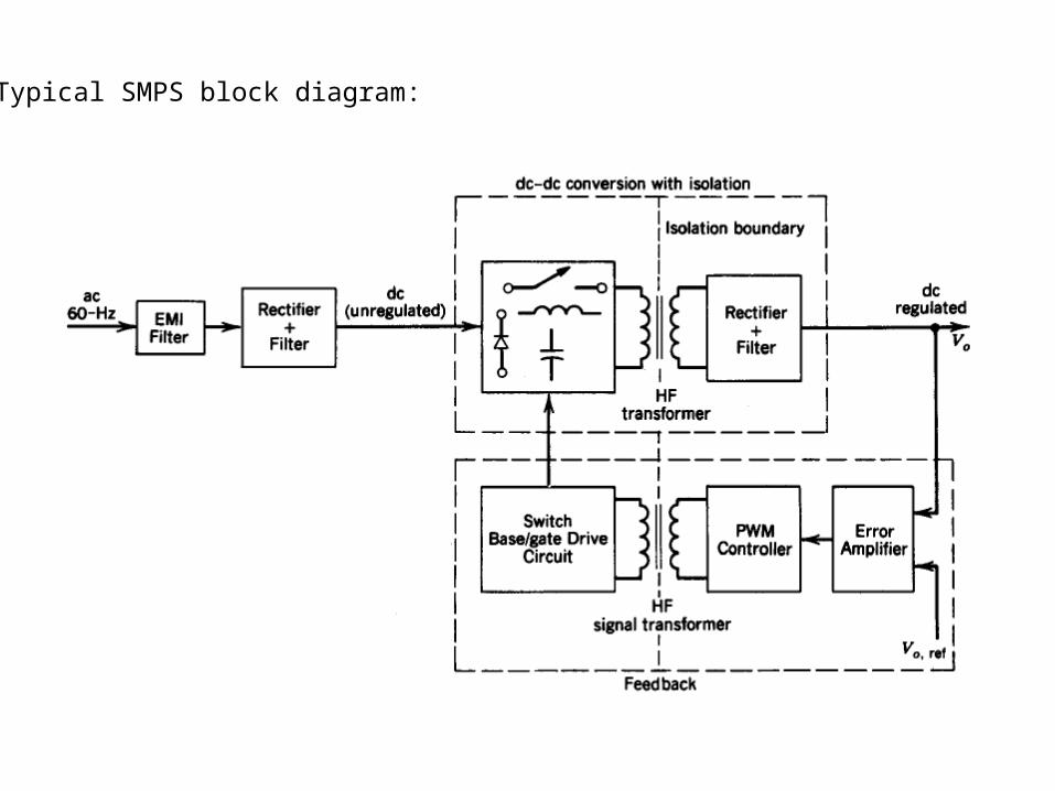
Typical SMPS block diagram:
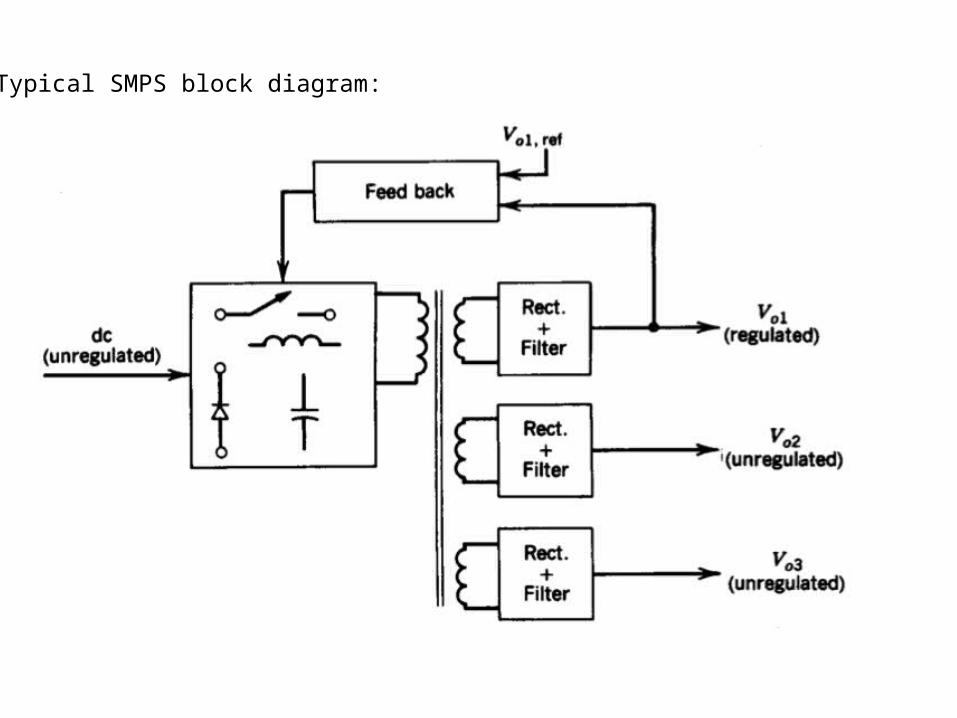
Typical SMPS block diagram:
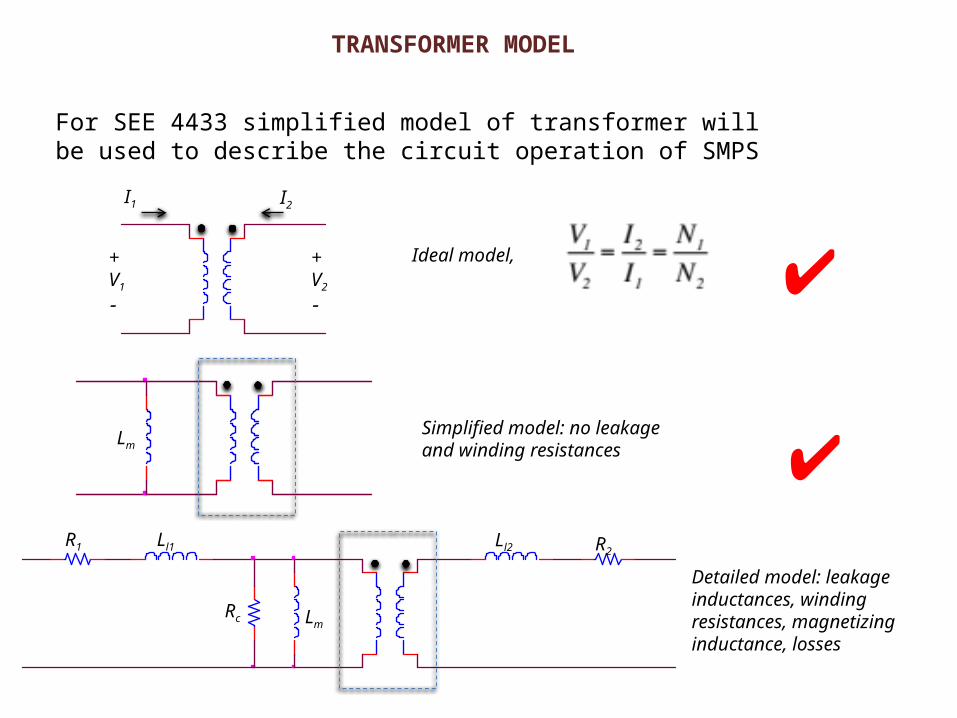
TRANSFORMER MODEL
For SEE 4433 simplified model of transformer will be used to describe the circuit operation of SMPS
Detailed model: leakage inductances, winding resistances, magnetizing inductance, losses
Simplified model: no leakage and winding resistances
+V1
+V2
I1 I2
✔Lm
Ll1R1
Rc Lm
Ll2 R2
✔Ideal model,
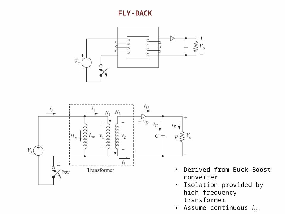
FLY-BACK
• Derived from Buck-Boost converter• Isolation provided by high frequency
transformer• Assume continuous iLm
FLY-BACK
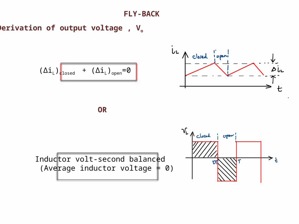
(ΔiL)closed + (ΔiL)open=0
Inductor volt-second balanced (Average inductor voltage = 0)
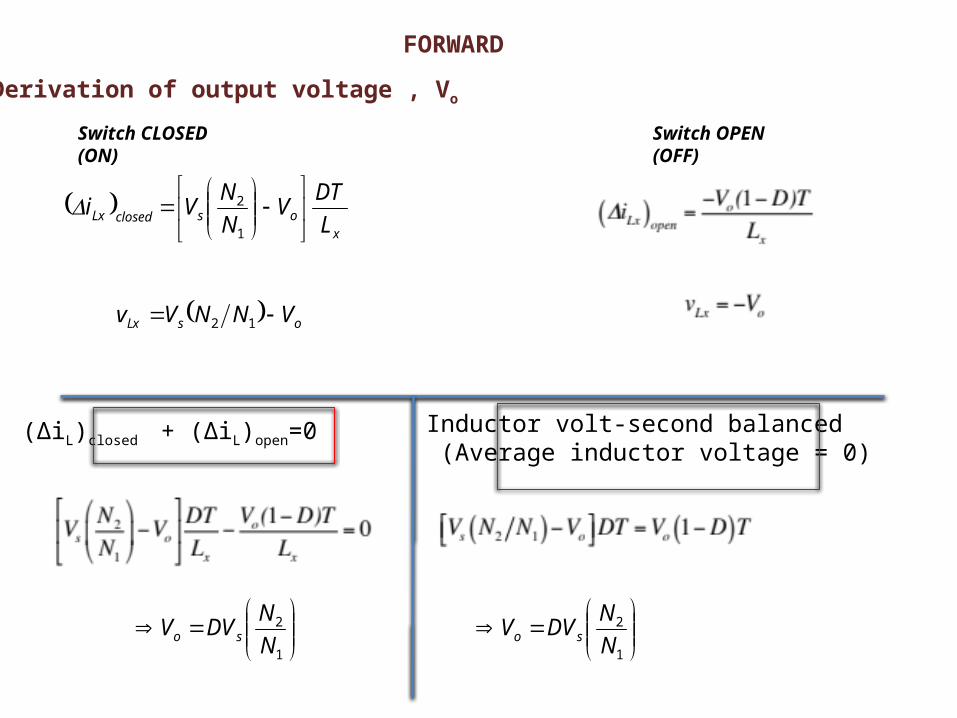
Derivation of output voltage , Vo
OR
FLY-BACK
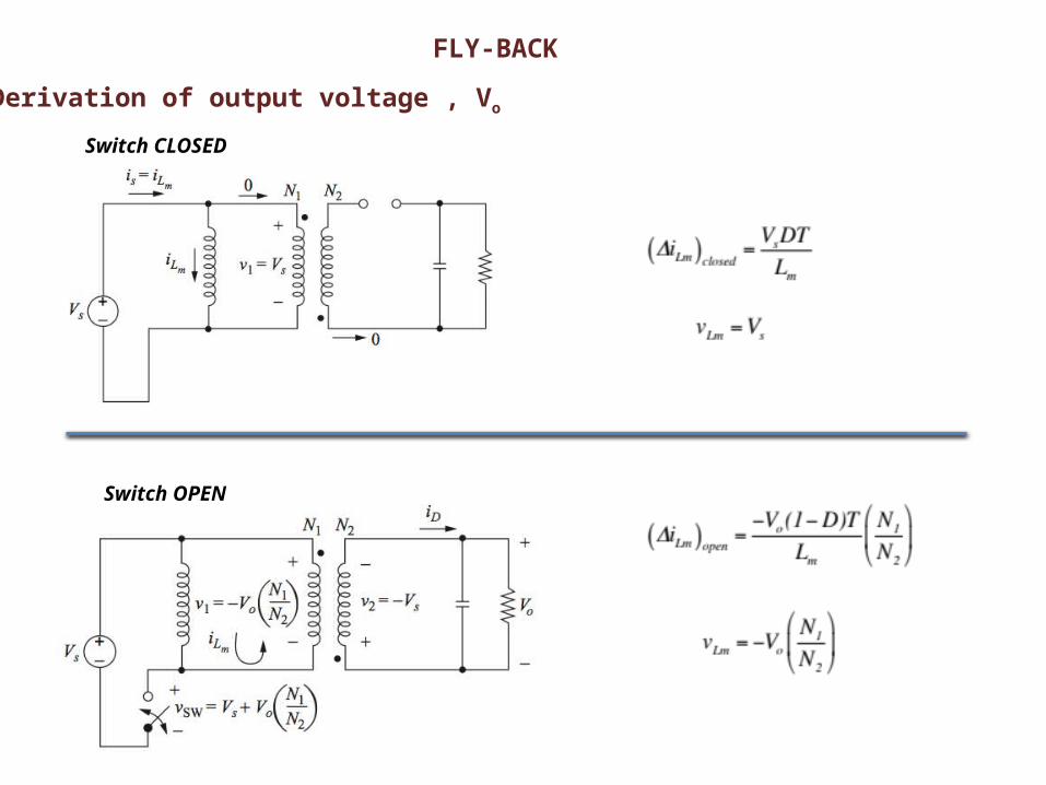
Derivation of output voltage , Vo
Switch CLOSED (ON)
Switch OPEN (OFF)
FLY-BACK
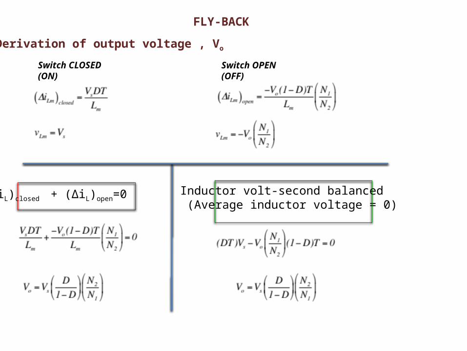
Switch CLOSED (ON)
Derivation of output voltage , Vo
Switch OPEN (OFF)
(ΔiL)closed + (ΔiL)open=0 Inductor volt-second balanced (Average inductor voltage = 0)
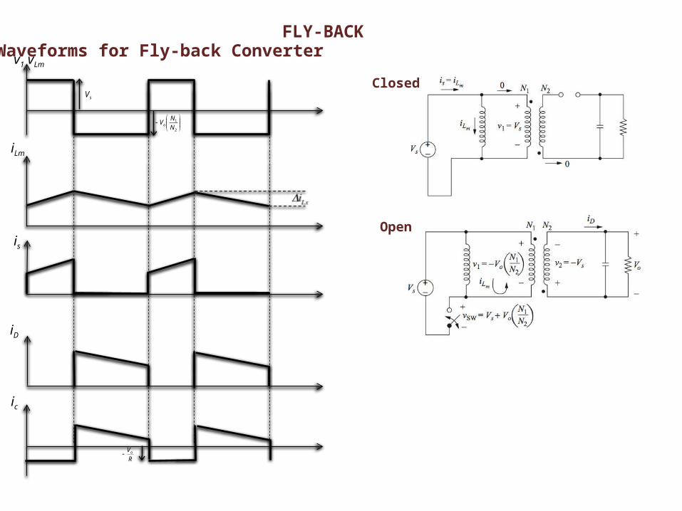
FLY-BACKWaveforms for Fly-back Converter
Closed
Open
v1 vLm
iLm
is
iD
ic
sV
2
1
N
NVo
R
Vo
FLY-BACK
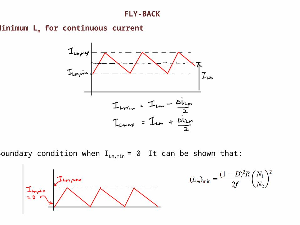
Minimum Lm for continuous current
Boundary condition when ILm,min = 0 It can be shown that:
FLY-BACK
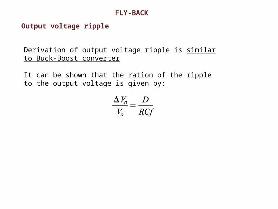
Output voltage ripple
Derivation of output voltage ripple is similar to Buck-Boost converter
It can be shown that the ration of the ripple to the output voltage is given by:
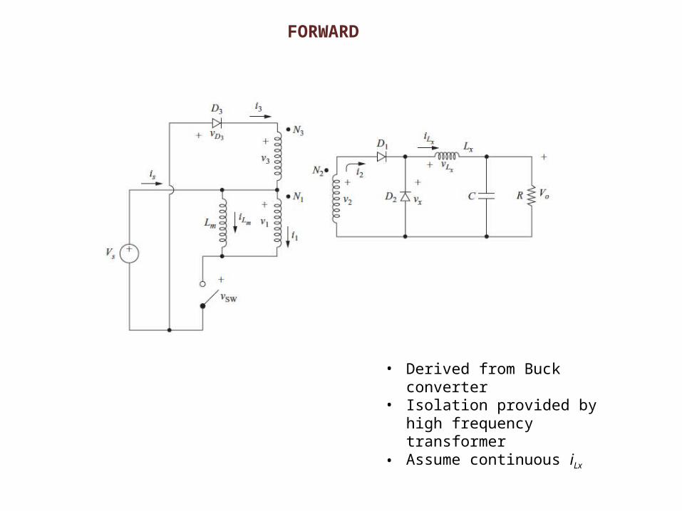
FORWARD
• Derived from Buck converter• Isolation provided by high
frequency transformer• Assume continuous iLx
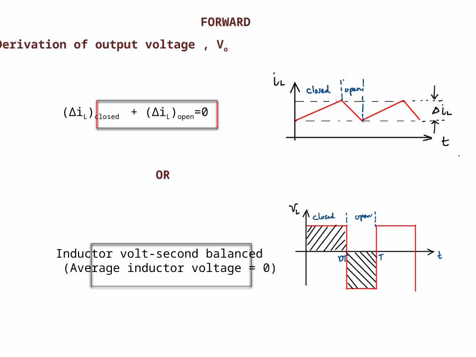
(ΔiL)closed + (ΔiL)open=0
Inductor volt-second balanced (Average inductor voltage = 0)
Derivation of output voltage , Vo
OR
FORWARD
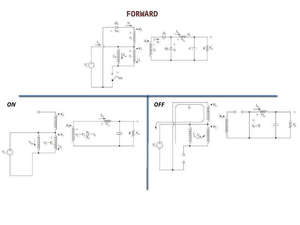
FORWARD
ON OFF
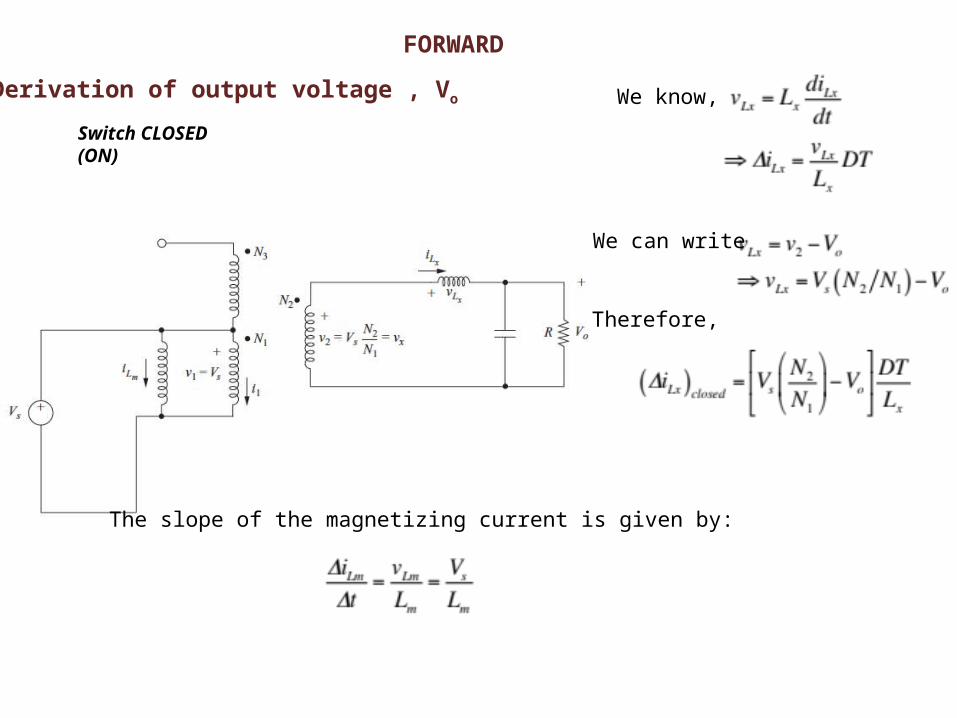
Derivation of output voltage , Vo
Switch CLOSED (ON)
FORWARD
We know,
We can write
Therefore,
The slope of the magnetizing current is given by:
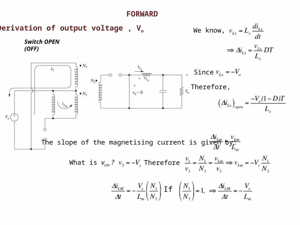
Derivation of output voltage , Vo
Switch OPEN (OFF)
FORWARD
We know,
Since
Therefore,
The slope of the magnetising current is given by:
What is vLm ? Therefore
If
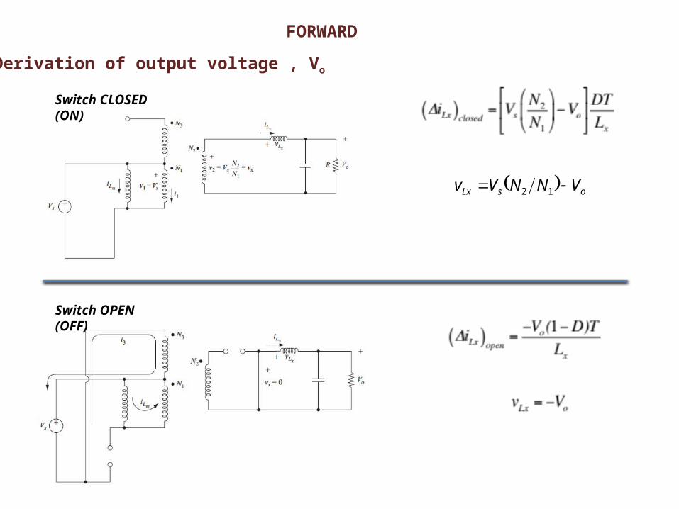
Derivation of output voltage , Vo
FORWARD
osLx VNNVv 12
Switch CLOSED (ON)
Switch OPEN (OFF)
Derivation of output voltage , Vo
FORWARD
(ΔiL)closed + (ΔiL)open=0 Inductor volt-second balanced (Average inductor voltage = 0)
Switch CLOSED (ON) Switch OPEN (OFF)
x
osclosedLx L
DTV
N
NVi
1
2
osLx VNNVv 12
1
2
N
NDVV so
1
2
N
NDVV so
FORWARD
ON
OFF
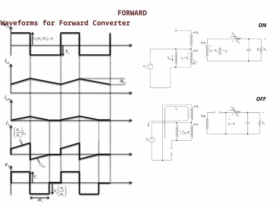
Waveforms for Forward ConvertervLx
iLx
iLm
i1
v1
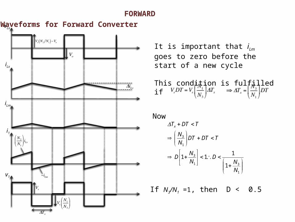
FORWARDWaveforms for Forward Converter
It is important that iLm goes to zero before the start of a new cycle
This condition is fulfilled if
Now
1
31
3
1
3
1
111
NN
DN
ND
TDTDTN
N
TDTTx
If N3/N1 =1, then D < 0.5
v1
vLx
iLx
iLm
i1
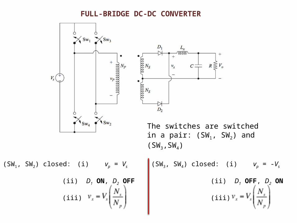
FULL-BRIDGE DC-DC CONVERTER
The switches are switched in a pair: (SW1, SW2) and (SW3,SW4)
(SW1, SW2) closed: (i) vp = Vs
(ii) D1 ON, D2 OFF
(iii)
(SW3, SW4) closed: (i) vp = -Vs
(ii) D1 OFF, D2 ON
(iii)
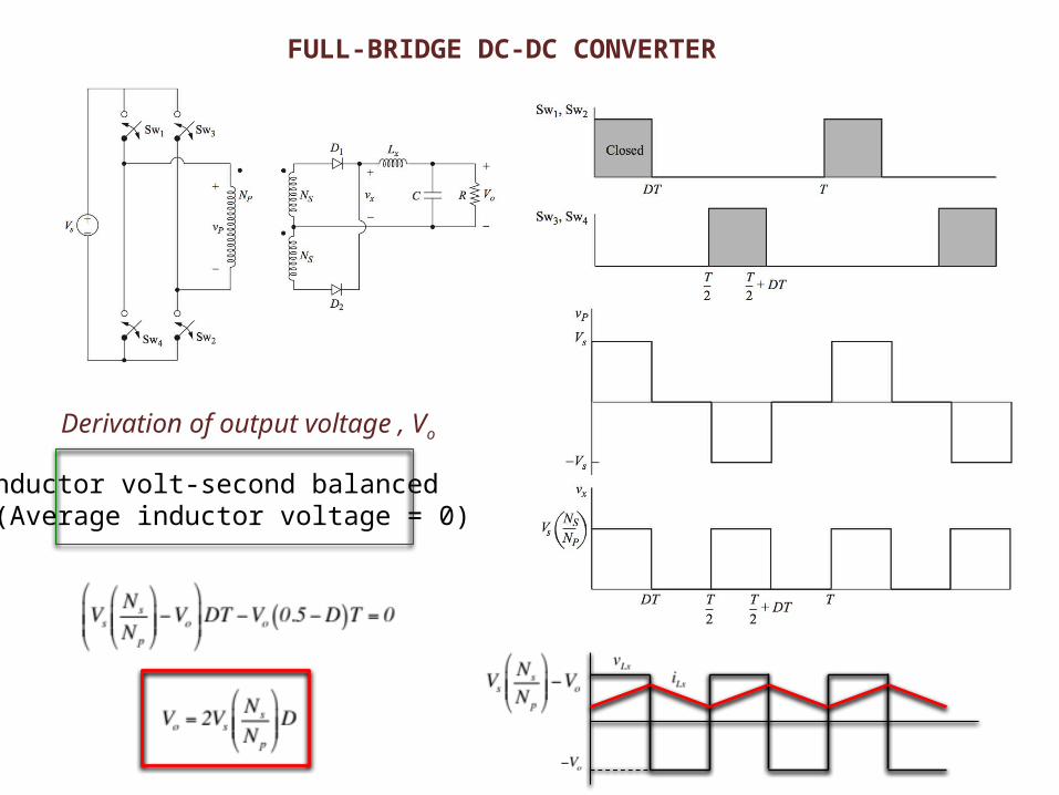
FULL-BRIDGE DC-DC CONVERTER
Derivation of output voltage , Vo
Inductor volt-second balanced (Average inductor voltage = 0)
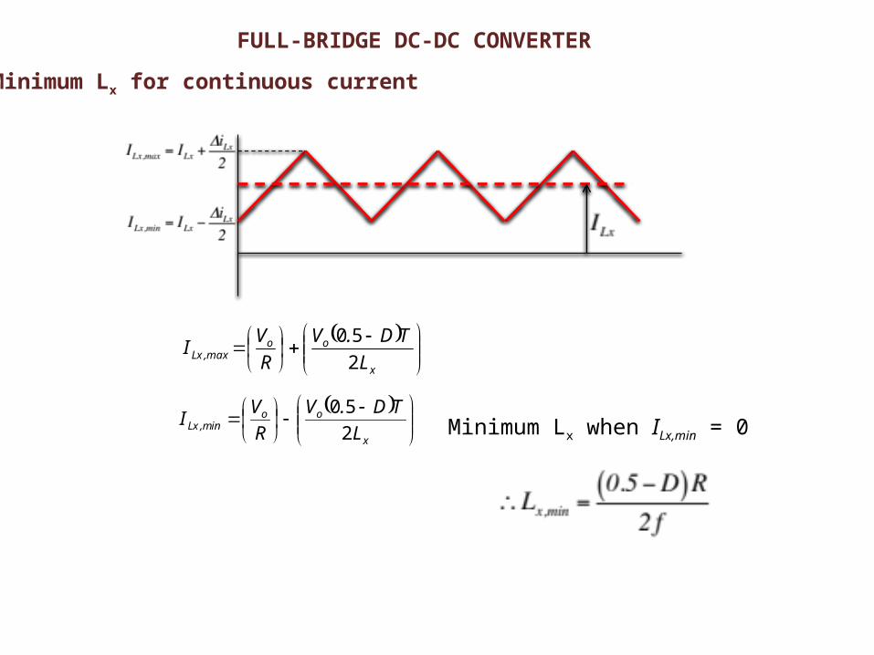
FULL-BRIDGE DC-DC CONVERTER
Minimum Lx for continuous current
Minimum Lx when ILx,min = 0
x
oomax,Lx L
TD.V
R
VI
2
50
x
ooinm,Lx L
TD.V
R
VI
2
50
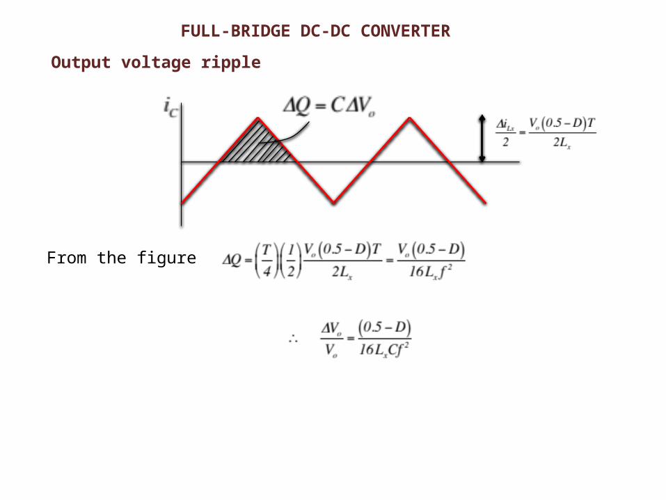
FULL-BRIDGE DC-DC CONVERTER
Output voltage ripple
From the figure
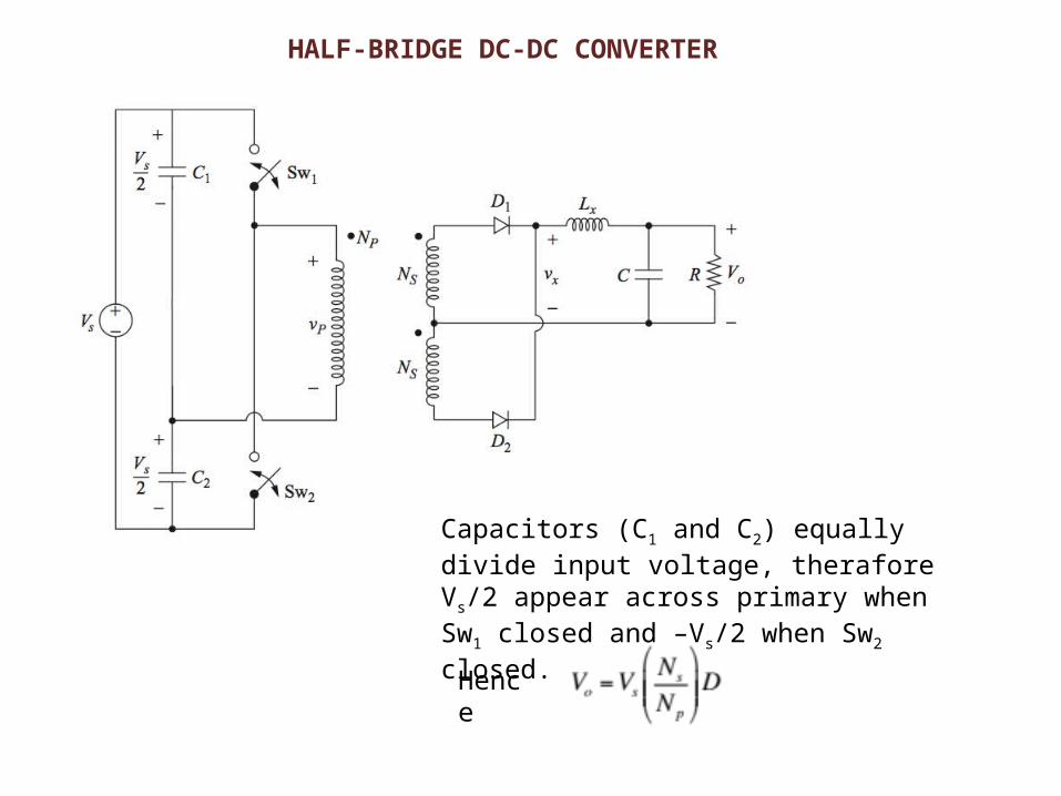
HALF-BRIDGE DC-DC CONVERTER
Capacitors (C1 and C2) equally divide input voltage, therafore Vs/2 appear across primary when Sw1 closed and –Vs/2 when Sw2 closed.
Hence
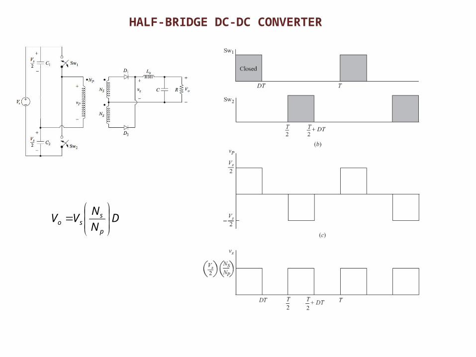
HALF-BRIDGE DC-DC CONVERTER
DN
NVV
p
sso