Embed Size (px)
Citation preview

Proceedings of the First International Conference on Press-in Engineering 2018, Kochi
- 563 -
Design and Installation of a Permanent Sheet Pile basement for the Manly Twenty95 Development
Davide CANTALI
Senior Sales Engineer , J Steel Australasia Pty Ltd
Email: [email protected]
Taro ITO
Project Manager, J Steel Australasia Pty Ltd
Email: [email protected]
ABSTRACT
Manly Twenty95 project is a luxury 6 story (24 apartment) residential development currently under construction in
Sydney Australia. J Steel Engineering had been constructed the permanent 4 level basement for an integral automated
carpark storage facility for this development in March 2018 using the ECO600S Silent Piler. Approximately 100m of
sheet pile wall was required for the basement structure. 21m long, 600mm wide hot rolled U piles were installed with
the Super Crush system in dense to very dense sands to support excavation depths of up to 12.5m. The bottom-up
technique with temporary propping was adopted by the builder. This paper identifies and discuss the design and
construction challenges for the permanent sheet pile basement, including; supporting large vertical column loads on the
sheet pile wall, durability aspects for providing a life beyond 50 years, and interfacing with temporary and permanent
lateral supports. In addition, the paper emphasizes interesting aspects related to the installation of the sheet pile system,
including use of the Super Crush for installing long sheet piles and problem solving of any other issues that arised
during the works.
Key words: Giken ECO600S, Permanent Sheet Pile Basement, Design, Axial load
1. Outline of the project
1.1. Place
The project site is located on the corner of the busy
intersection of Belgrave Street and Sydney Road in Manly,
Sydney, NSW Australia – a 5min. walk from the surf
beach and opposite to Manly Oval. Adjacent to the site is
an existing telecommunications exchange and a heritage
listed sandstone church (Fig. 1).
Fig. 1 Site location
Proceedings of the First International Conference on Press-in Engineering 2018, Kochi
- 564 -
1.2. Background and objectives of the project
The project site is a small congested site
approximately 1000m2 in area. Grocon are developing the
site into 4 levels of 1, 2 & 3 bedroom luxury apartments in
addition to some commercial and retail space. To service
the building, a 4 level automated carpark within a
permanent basement will be constructed. A maximum
excavation depth of ~12.5m is required to construct the
carpark.
2. Structural type and piling method
2.1. Site condition
The site is within the busy commercial/residential
precinct of Manly and was formerly used as a
park/carpark (Photo 1).
Due to the restricted site space and concerns
regarding noise within the retail area and vibration
damaging heritage listed buildings, suitable retaining wall
systems were carefully considered.
Photo 1. Site Image
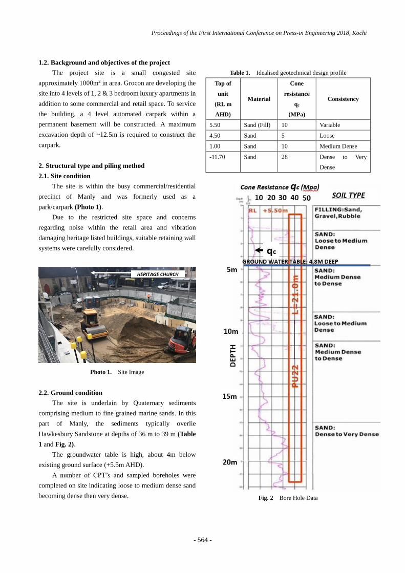
2.2. Ground condition
The site is underlain by Quaternary sediments
comprising medium to fine grained marine sands. In this
part of Manly, the sediments typically overlie
Hawkesbury Sandstone at depths of 36 m to 39 m (Table
1 and Fig. 2).
The groundwater table is high, about 4m below
existing ground surface (+5.5m AHD).
A number of CPT’s and sampled boreholes were
completed on site indicating loose to medium dense sand
becoming dense then very dense.
Table 1. Idealised geotechnical design profile
Top of
unit
(RL m
AHD)
Material
Cone
resistance
qc
(MPa)
Consistency
5.50 Sand (Fill) 10 Variable
4.50 Sand 5 Loose
1.00 Sand 10 Medium Dense
-11.70 Sand 28 Dense to Very
Dense
Fig. 2 Bore Hole Data

Proceedings of the First International Conference on Press-in Engineering 2018, Kochi
- 565 -
2.3. Structural type & design
The project required a permanent basement wall for
a design life of 50 years. The basement would be
constructed bottom up and required a maximum 12.5m
excavation. In the temporary case, the walls would be
supported by temporary anchoring and bracing, and by
concrete slabs at each of the basement slab levels in the
permanent scenario.
The initial Geotechnical report provided by the
client suggested for the retaining wall system either of;
1) A secant pile wall comprising interlocking
Continuous Flight Auger (CFA) piles or CFA piles with
jet grouted columns between the piles.
2) Soil mixed wall systems constructed using
specialised equipment to either blend cement with the
in-situ soils to create a soil-cement mix.
The conventional sheet piles installation method
using a vibration hammer was NOT recommended for
the use on this site as there were movement sensitive
structures adjacent to the excavation. We proposed the
Press-in Piling method using our ECO600S with the
design described below.
A PU22 pile section, supplied as 600mm wide U
piles, was determined as the preferred section to support
the earth and water pressures in the temporary and
permanent case (Fig. 3).
Fig. 3 PU22 pile properties

Proceedings of the First International Conference on Press-in Engineering 2018, Kochi
- 566 -
As per the client design requirement the walls also
had to support permanent surcharge load from the
adjacent pedestrian footpaths and roadways (up to
20kPa) as well as temporary construction load from the
plant, equipment and materials (up to 50kPa).
Fig. 4 section view shows a typical design
arrangement for the permanent case.
In addition to supporting earth and water pressures,
the walls were required to support axial load from
permanent columns supporting the superstructure above.
The maximum factored column loads of up to
2141kN were supported on 2, 3 or 4 U piles. Fig. 5
shows column loading. Also the sheet pile/wall was
required to provide cut-off to limit groundwater flow into
the excavation.
Fig. 4 PU22 pile properties

Proceedings of the First International Conference on Press-in Engineering 2018, Kochi
- 567 -
Fig. 5 Column Loadings
2.4. Durability
In accordance with the Australian Standard AS2159,
the site was classified as non-aggressive to steel piling. A
corrosion allowance of 0.025mm/yr was allowed on the
front and back faces of the wall, reducing thickness by
1.25mm per side over 50 years (2.5mm overall). In
addition, on the inside within the basement excavation,
the sheet piles will be painted and maintained for a 25
year life.
The appropriate reductions in section modulus and
moment of inertia were determined and applied in the
design calculation to confirm satisfactory structural
performance at end of life.
2.5. Piling method
The geotechnical report stipulated to conduct further
testing to determine the appropriate disposal options of
ground water as it detected hydrocarbons within the
samples collected from the monitoring well.
Initially the press-in with water jetting was planned.
However, considering the counter measure against
possibly contaminated groundwater collected from the
jetting operation, and a possible disturbance to nearby
ground/ structure by high pressure jetting, J Steel
proposed the press-in with augering with ECO 600S.
3. Press-in piling
3.1. Layout
The layout of the sheet piles can be seen in Fig. 6.
The sheet pile length varies depending on the excavation
depth.

Proceedings of the First International Conference on Press-in Engineering 2018, Kochi
- 568 -
Fig. 6 Layout of Sheet Piles
3.2. Productivity
We used 1 no. x press-in machine (ECO 600S) for
entire project. The outline of our program on the site is
described in Table 2;
Table 2. Outline of Site Program
Noticeably, the actual working (piling) day was 34
out of 60 business days we stayed on the site. The causes
of the stand down of our resources will be explained in the
next section.
The maximum length of sheet pile installed within a
day was 9 Sheets x 21.0m = 189 m which was recorded on
17-January 2018.
3.3. Resources
3.3.1. Major plant and equipment
The major equipment use on site are listed below;
- 1 no. Press-in ECO 600S - Giken/ JSteel
- 1 no. 80 ton Crawler Crane - Keller/ WGC
- 1 no. 30 ton Crawler Crane - Keller/ WGC
- 1 no. 250 cfm Air Compressor - Keller/ Coates
- 1 no. 5 ton Excavator - Keller/ Coates
- 1 no. Welding Machine – Keller
- 1 no. Oxy Cut set – Keller
3.3.2. Site personnel
The site personnel to execute the works are listed
below;
- T. Ito – Engineer (J Steel)
- T. Ueta – Operation of ECO 600S (Giken)
- M. Machida – Leading hand (Giken)
- K. Fukumori – Offsider (Giken)
- C. Carde – Supervisor (Keller)
- L. Copley – Welder (Keller)
- R. Coombes – Offsider (Keller)
- 80 Ton Crane Operator (Keller/ WGC)
- 30 Ton Crane Operator (Keller/ WGC)
3.4. Encountered difficulties
3.4.1. Delay of existing sub-station removal
We mobilised resources on 13/12/2017 based on the
Sub-station located within the site would be removed in a
week time. However this did not happen until 27/2/2018.
This delay had resulted in significant low productivity
and increase of work load. We were also forced to reduce
our storage area and increased congestions on the site.
The originally planned foot print was as per below Fig. 7.
This was changed drastically due to the existence of the
Sub-station. Cranes were needed to increase their
capacity to enable to reach longer distance. Sheet piles
were needed to store on top of the existing Telecom
Building.
Fig. 7 Planned Foot Print
The existence of Sub-station also affected the
sequence of our piling works. Closing the sheet pile wall
as a “box” (clutched) required a careful planning.
Closing at a 90 degree corner is a normal practice as it
provides greater flexibility to absorb material and

Proceedings of the First International Conference on Press-in Engineering 2018, Kochi
- 569 -
construction tolerance. However due to the existence of
sub-station we needed to re-plan the piling sequence and
compromised to close the wall at 45 degree (Number 6 at
Fig. 7), which eventually took us for a few days to close
because of the the limited flexibility compare to a 90
degree corner and the deviation of the wall was more
than what we anticipated.
Moving the Piler from one place to another took
about half a day. The 27m casing auger was required to
be removed and dismantled. Associated plant and
equipment need to be re-organised.
Initially we anticipated only twice for moving the
Piler. But after we changed the sequence we had to move
5 time which increased 3 movements from the original
plan.
3.4.2. Piling platform level issue
1m deep x 2m wide trench was to be excavated
along the perimeter line before we commence the piling
works. However the client found an existing high voltage
cables along the boundary line and could not create the
trench (Fig. 8).
The failure to excavate over the boundary resulted
in extending piles for 1m and slower productivity while
existing cables close to the site boundary had been
identified and protected.
Fig. 8 Piling Platform Level
3.4.3. Tolerance of sheet pile material
The Fig. 9 shows the comparison between the actual
distance and the design distance of sheet pile walls. As
can be seen approximately 270mm was lengthened due
to extra 5-6mm width of each sheet pile.
These extra lengths were absorbed at the corner
which had greater flexibility.
Fig. 9 Tolerance of Sheet Pile Material

Proceedings of the First International Conference on Press-in Engineering 2018, Kochi
- 570 -
3.4.4. Ground Movement due to Pre-Drilling
As can be seen in the Photo 2 and 3, we observed
some crack and subsidence were caused, possibly by our
augering works along the perimeter.
The client used plywood and fence posts and
excavated the site about 1m before we commence our
works (refer to Photo 1).
Patched repair of path was done by the client and
fortunately no serious damaged been observed.
Photo 2. Pedestrian Path 1
Photo 3. Pedestrian Path 2
3.4.5. Execution team on site
Fig. 10 shows the contractual formation of the
project. Although we had engaged with a well-known
specialist contractor, Keller, they had no experience in
press-in operation. Therefore, we had 3 members from
Giken including an experienced operator during the
course of the project to ensure we provide the best
performance.
Fig. 10 Contractual Formation
4. Concluding remarks
This paper described the outline of the project
including how we carried out the design for the basement
as well as the construction works. We particularly spent a
space for problems we encountered on site which we
would like to share with other members for future use.
5. Acknowledgements
This project would not have been possible without
full support from Giken's personnel from the tender stage
to the completion of the site works. We would like to
extend our sincere appreciation to all of Giken team.
References
Australian Standard 2159. 2009. Piling - Design and
Installation, Council of Standards Australia.
Douglas Partners Pty Ltd. 2016. Geotechnical
Investigation, Proposed Residential Development,
85028.00.R.001.Rev1.
J Steel. 2017. Design Report – Sheet Pile Wall,
JE-7003-DR-04.
Arcelor Mittal. 2017. Arcelor Mittal Sheet Piling.
Catalogue.