Embed Size (px)
Citation preview

Design Challenges for Next Generation, High Speed Ethernet:40 and 100 GbE
Sponsored by: Ethernet Alliance®
Panel Organizer: John D’Ambrosia, Sr. Scientist
Force10 Networks
Chair, IEEE 802.3ba Task Force
DesignCon 2009
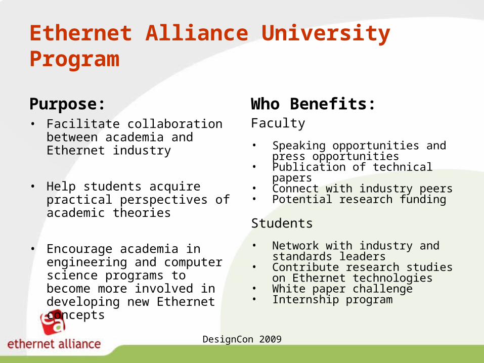
Ethernet Alliance University Program
Purpose:• Facilitate collaboration between
academia and Ethernet industry
• Help students acquire practical perspectives of academic theories
• Encourage academia in engineering and computer science programs to become more involved in developing new Ethernet concepts
Who Benefits:Faculty
• Speaking opportunities and press opportunities
• Publication of technical papers• Connect with industry peers• Potential research funding
Students
• Network with industry and standards leaders
• Contribute research studies on Ethernet technologies
• White paper challenge• Internship program
DesignCon 2009
January 2009
Academic Members
Page 4 © 2009 Dell’Oro Group
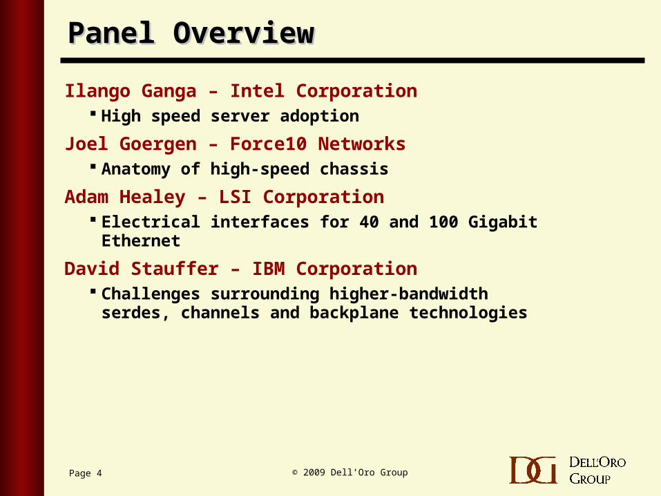
Panel OverviewPanel Overview
Ilango Ganga – Intel Corporation High speed server adoption
Joel Goergen – Force10 Networks Anatomy of high-speed chassis
Adam Healey – LSI Corporation Electrical interfaces for 40 and 100 Gigabit Ethernet
David Stauffer – IBM Corporation Challenges surrounding higher-bandwidth serdes,
channels and backplane technologies
Page 5 © 2009 Dell’Oro Group
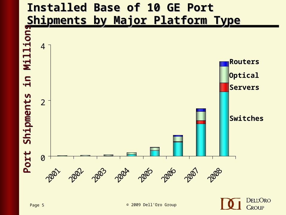
Installed Base of 10 GE Port Shipments by Installed Base of 10 GE Port Shipments by Major Platform TypeMajor Platform Type
Por
t S
hipm
ents
in M
illio
nsP
ort
Shi
pmen
ts in
Mill
ions
Servers
Optical
Switches
Routers
0
2
4
Page 6 © 2009 Dell’Oro Group
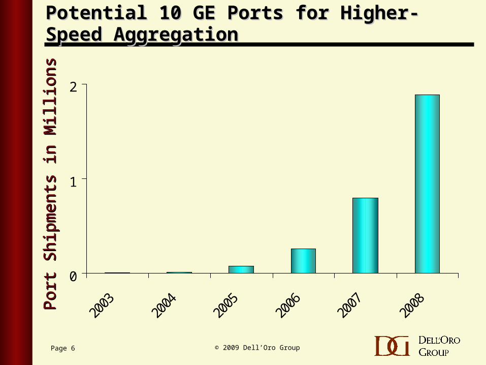
Potential 10 GE Ports for Higher-Speed Potential 10 GE Ports for Higher-Speed AggregationAggregation
Por
t S
hipm
ents
in M
illio
nsP
ort
Shi
pmen
ts in
Mill
ions
0
1
2
2003
2004
2005
2006
2007
2008
Page 7 © 2009 Dell’Oro Group
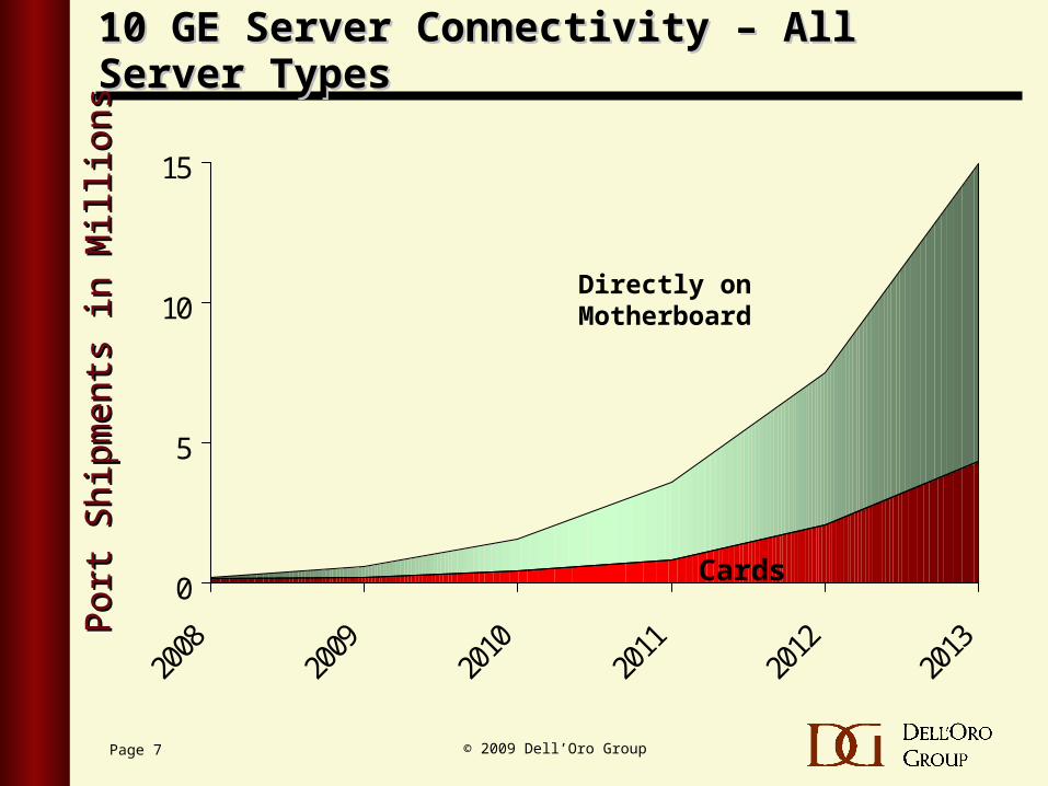
10 GE Server Connectivity – All Server Types10 GE Server Connectivity – All Server TypesP
ort
Shi
pmen
ts in
Mill
ions
Por
t S
hipm
ents
in M
illio
ns
0
5
10
15
Cards
Directly on Motherboard
Design Challenges for Next Gen Ethernet −Server End Station perspective
Ilango GangaCommunications Architect , Intel Corporation
Editor-in-Chief, IEEE P802.3ba Task Force
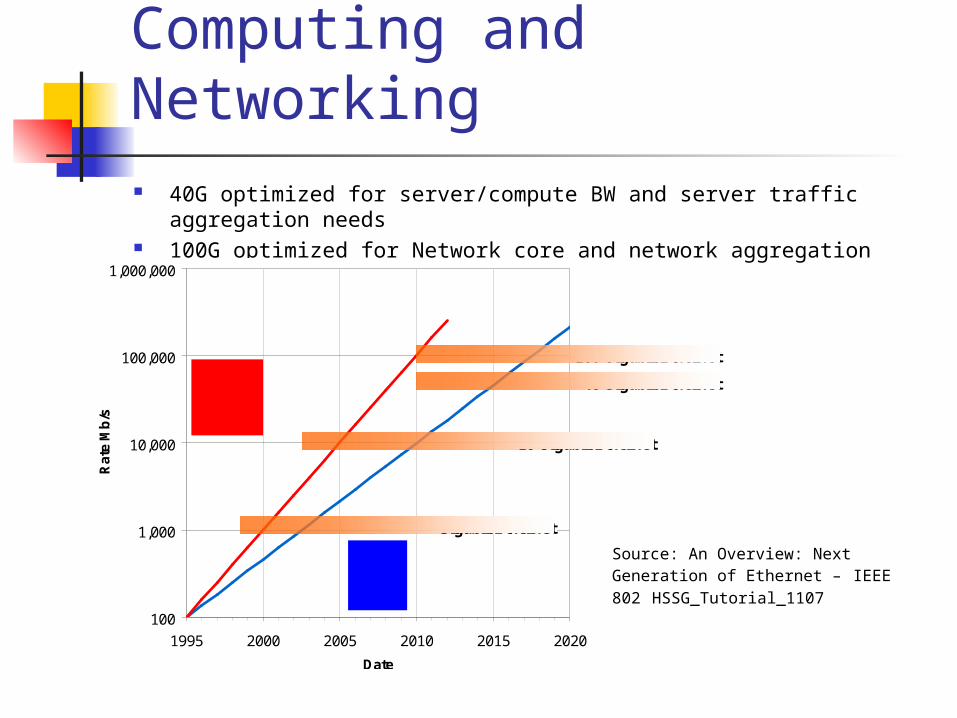
40GbE and 100GbE Computing and Networking 40G optimized for server/compute BW and server traffic aggregation
needs 100G optimized for Network core and network aggregation needs
100
1,000
10,000
100,000
1,000,000
1995 2000 2005 2010 2015 2020
Date
Rat
e M
b/s
CoreNetworkingDoubling≈18 mos
ServerI/O
Doubling≈24 mos
Gigabit Ethernet
10 Gigabit Ethernet
100 Gigabit Ethernet
40 Gigabit Ethernet
Source: An Overview: Next Generation of Ethernet – IEEE 802 HSSG_Tutorial_1107
Server I/O BW drivers
Higher system processing capability Multi-core processors Higher speed memory, systems bus, and next gen. process
technologies Server Virtualization
Consolidation of multiple logical servers in a single physical server Converged networking and storage
Multiple I/O connections converging to single connection with fabric virtualization
Clustered servers Scientific, financial, oil/gas exploration, engineering workloads
Internet applications IPTV, Web 2.0
Transition to 10GbE and Multiple 10GbE will drive the future transition to 40GbE
System capabilities & design constraints
System & I/O capabilities Today’s Server systems are capable of 10GbE
I/O convergence happening at 10GbE Systems capable of handling multiple 10GbE from 2009+
Next generation I/O bus upgrades (for e.g. PCIe Gen3) Blade backplanes/midplanes are capable of multiple 10G
lanes, 4 lane backplanes are scalable to 40G (KR KR4)
Design Constraints Performance Cost Power Density (Form factor/size)
High speed LAN controllers
Today’s 10G LAN controllers handle more and more advanced packet processing in hardware, for example:
Packet classification I/O Virtualization Protocol offloads MAC/Serdes Handle dual Ports
Design challenges for packet processing capabilities at 40G speeds
Fixed Power constrains for PCI adapters, Blade adapters Advanced packet processing at multiple 10G (e.g. 4x10G) and 40G Integration of 40G MAC and serdes technologies
Can leverage multiple 10G serdes technology Host bus upgrades to next gen system I/O speeds Convergence of NIC/HBA/Virtualization models in a single controller SW challenges to scaling
Summary
Server consolidation, storage & network convergence, cluster, and video applications will drive the need for higher I/O bandwidths
Consolidation with 10G / multiple 10G, and then to 40G Multi-core processors, next generation System busses,
and blade backplane/midplane systems expected to be capable of 40G I/O speeds in 3 years time frame
Performance/Cost/Power constraints will drive the design choices for 40G Network controllers
Implementations expected to leverage 10G technologies for faster time to market
Copyright © 2008 Force10 Networks, Inc. All rights reserved.
The Call for Industry Research on Next-Generation Electrical Signaling
Joel GoergenVice President of Technology,Chief Scientist
Force10 Networks
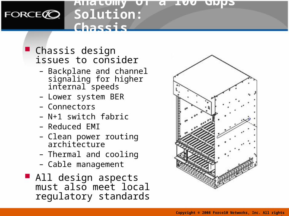
Anatomy of a 100 Gbps Solution:Chassis
Chassis design issues to consider– Backplane and channel
signaling for higher internal speeds
– Lower system BER– Connectors– N+1 switch fabric – Reduced EMI– Clean power routing
architecture– Thermal and cooling– Cable management
All design aspects must also meet local regulatory standards
Copyright © 2008 Force10 Networks, Inc. All rights reserved.
Copyright © 2008 Force10 Networks, Inc. All rights reserved.
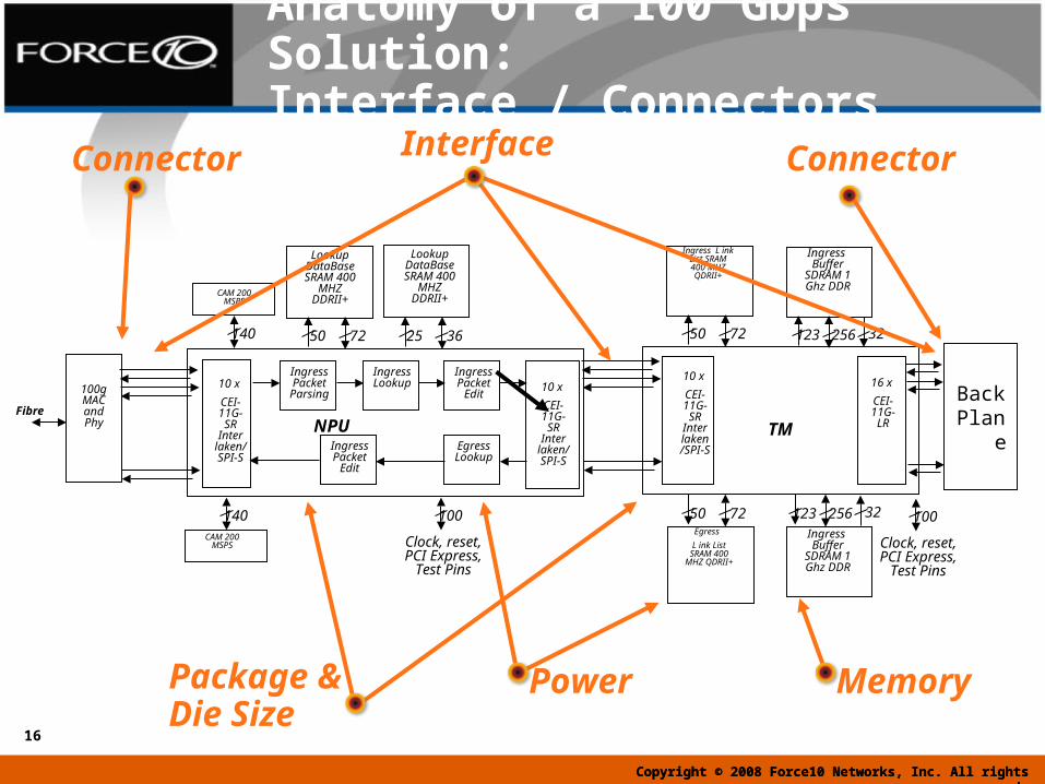
Anatomy of a 100 Gbps Solution:Interface / Connectors
Copyright © 2008 Force10 Networks, Inc. All rights reserved.
16
NPU
CAM 200 MSPS
140
Lookup DataBase SRAM 400
MHZ DDRII+
50 72
Lookup DataBase SRAM 400
MHZ DDRII+
25 36
140CAM 200
MSPS
10 x
CEI-11G-SR
Inter laken/S
PI-S
Ingress Packet Parsing
Ingress Lookup
Ingress Packet
Edit10 x
CEI-11G-SR
Inter laken/SPI-S
Egress Lookup
Ingress Packet
Edit
100g MAC and Phy
Fibre
Ingress L ink List SRAM 400 MHZ QDRII+
50 72
Ingress Buffer
SDRAM 1 Ghz DDR
123 256 32
10 x
CEI-11G-SR
Inter laken/SPI-S
Ingress Buffer
SDRAM 1 Ghz DDR
123 256 32Egress
L ink List SRAM 400
MHZ QDRII+
50 72
16 x
CEI-11G-LRTM
Clock, reset, PCI Express,
Test Pins
100
Clock, reset, PCI Express,
Test Pins
100
BackPlane
Power Memory
Interface
Package &Die Size
ConnectorConnector
Copyright © 2008 Force10 Networks, Inc. All rights reserved.
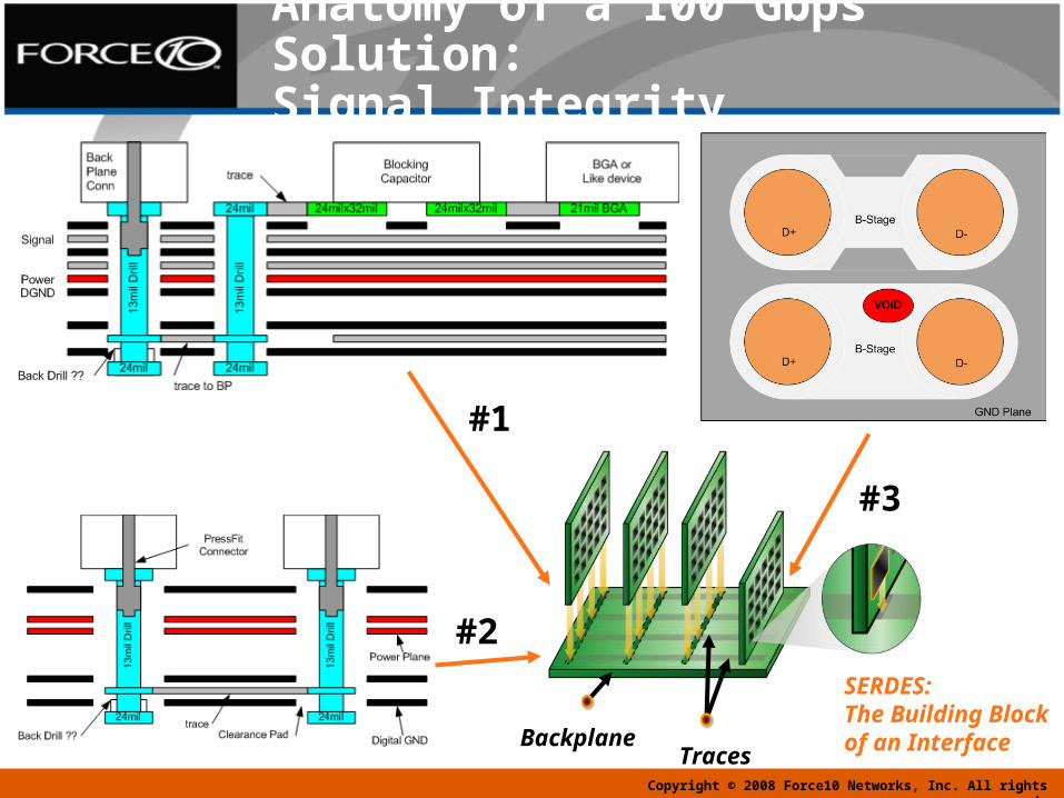
Anatomy of a 100 Gbps Solution:Signal Integrity
Backplane
SERDES:The Building Blockof an Interface
Traces
#1
#2
#3
Design Challenges for Next-Generation, High-Speed
Ethernet: 40 and 100 GbE
Adam HealeyLSI Corporation
19Healey DesignCon 2009
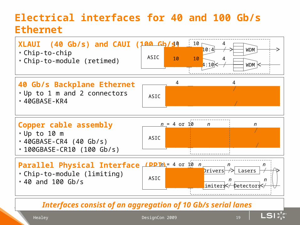
Electrical interfaces for 40 and 100 Gb/s Ethernet
Interfaces consist of an aggregation of 10 Gb/s serial lanes
• Chip-to-chip• Chip-to-module (retimed)
XLAUI (40 Gb/s) and CAUI (100 Gb/s)
• Up to 1 m and 2 connectors• 40GBASE-KR4
40 Gb/s Backplane Ethernet
• Up to 10 m• 40GBASE-CR4 (40 Gb/s)• 100GBASE-CR10 (100 Gb/s)
Copper cable assembly
• Chip-to-module (limiting)• 40 and 100 Gb/s
Parallel Physical Interface (PPI)
ASIC
Limiters
Lasers
Detectors
Driversn = 4 or 10
n n
n n
n
n
n
ASIC
n = 4 or 10
n n
n n
n
10:4
4:10
ASIC
10 10 4WDM
WDM10 10 4
ASIC
4
4
4
4
20Healey DesignCon 2009
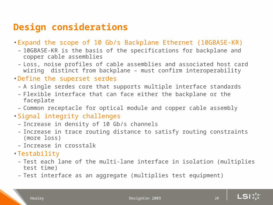
Design considerations
• Expand the scope of 10 Gb/s Backplane Ethernet (10GBASE-KR)– 10GBASE-KR is the basis of the specifications for backplane and copper
cable assemblies– Loss, noise profiles of cable assemblies and associated host card wiring
distinct from backplane – must confirm interoperability
• Define the superset serdes– A single serdes core that supports multiple interface standards– Flexible interface that can face either the backplane or the faceplate– Common receptacle for optical module and copper cable assembly
• Signal integrity challenges– Increase in density of 10 Gb/s channels– Increase in trace routing distance to satisfy routing constraints (more loss)– Increase in crosstalk
• Testability– Test each lane of the multi-lane interface in isolation (multiplies test time)– Test interface as an aggregate (multiplies test equipment)
21Healey DesignCon 2009
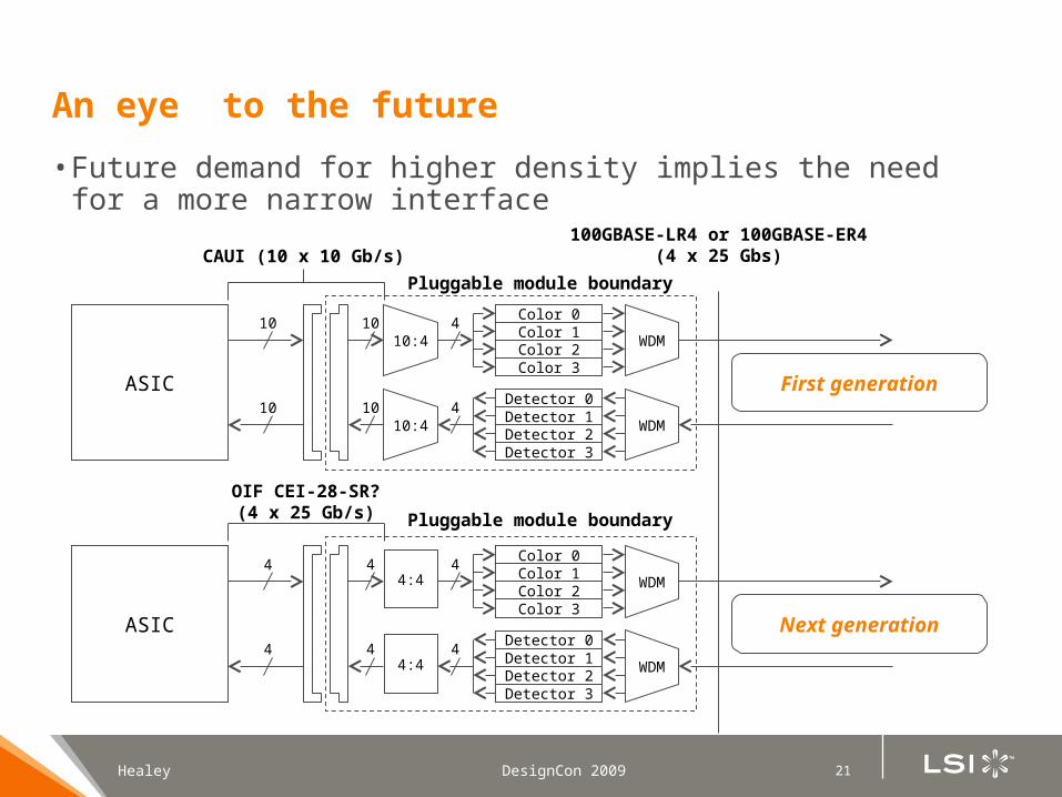
An eye to the future
• Future demand for higher density implies the need for a more narrow interface
Detector 0Detector 1Detector 2Detector 3
WDM10:4410
Color 0Color 1Color 2Color 3
WDM10:4410
ASIC10
10
Detector 0Detector 1Detector 2Detector 3
WDM44
Color 0Color 1Color 2Color 3
WDM44
ASIC4
4
CAUI (10 x 10 Gb/s)100GBASE-LR4 or 100GBASE-ER4
(4 x 25 Gbs)
OIF CEI-28-SR?(4 x 25 Gb/s) Pluggable module boundary
Pluggable module boundary
First generation
Next generation
4:4
4:4
IBM Server and Technology Group
DesignCon 2009 © 2009 IBM Corporation
Design Challenges for Next-Generation, High-Speed Ethernet: 40 and 100 GbE
DesignCon 2009February 4, 2009
David R. StaufferSenior Technical Staff MemberIBM ASIC Design CenterOIF Physical & Link Layer Working Group Chair
IBM Server and Technology Group
© 2009 IBM CorporationDesignCon 2009
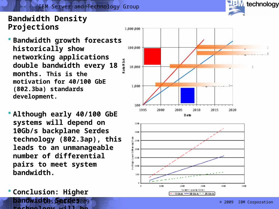
Bandwidth growth forecasts historically show networking applications double bandwidth every 18 months. This is the motivation for 40/100 GbE (802.3ba) standards development.
Although early 40/100 GbE systems will depend on 10Gb/s backplane Serdes technology (802.3ap), this leads to an unmanageable number of differential pairs to meet system bandwidth.
Conclusion: Higher bandwidth Serdes technology will be required. ~25 Gb/s is optimal.
Bandwidth Density Projections
IBM Server and Technology Group
© 2009 IBM CorporationDesignCon 2009
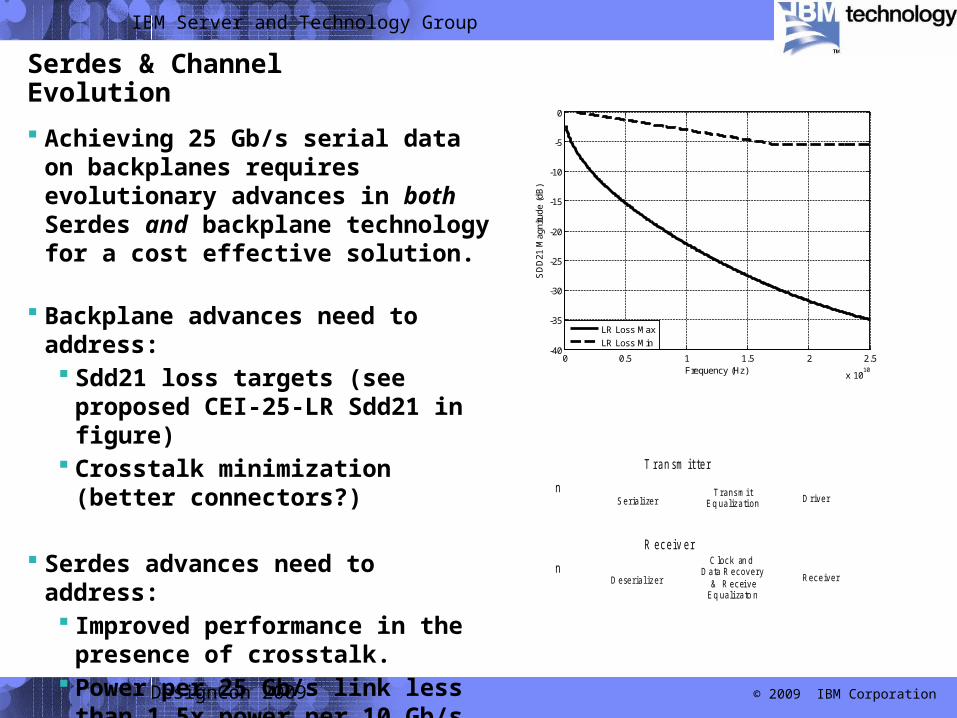
Achieving 25 Gb/s serial data on backplanes requires evolutionary advances in both Serdes and backplane technology for a cost effective solution.
Backplane advances need to address: Sdd21 loss targets (see proposed
CEI-25-LR Sdd21 in figure) Crosstalk minimization
(better connectors?)
Serdes advances need to address: Improved performance in the
presence of crosstalk. Power per 25 Gb/s link less than
1.5x power per 10 Gb/s link.
Serdes & Channel Evolution
0 0.5 1 1.5 2 2.5
x 1010
-40
-35
-30
-25
-20
-15
-10
-5
0
Frequency (Hz)
SD
D21
Mag
nitu
de (
dB)
LR Loss Max
LR Loss Min
SerializerTransmit
Driver
T ran sm it te r
n
Deserial izer
Clock an d
Receiver
R ece iv er
n
Eq ualization
Data Recovery& Receive
Eq ualizato n
IBM Server and Technology Group
© 2009 IBM CorporationDesignCon 2009
Significant Issues
Backplane Technology: Sdd21 Insertion Loss must be achieved without significant impacts to
manufacturing yield or cost. Advanced materials may be required but only if acceptable manufacturing
yield is achievable. Advanced design techniques (i.e. broadside coupling) may be required. Better connectors are needed to minimize crosstalk, reflections, etc.
Serdes Technology: Signaling solution must be evolutionary to meet power targets and allow
current levels of integration on ASIC chips. Crosstalk is a significant concern at higher baud rates. Current crosstalk
cancellation schemes do not work generically in backplane environments. FEC schemes can achieve performance but at the cost of power and
latency. So far this cost has not found market acceptance. Multi-level signaling schemes have not shown promise.

Questions?