Embed Size (px)
Citation preview
OPERATOR’S MANUAL
Manual # SB3W_10_02
February 2010

- 1 -
TABLE OF CONTENTS
HLA Attachments
8082 Rd 129
Listowel, ON N4W 3G8
Canada
1-866-567-4162
[email protected] www.horstwelding.com
Introduction, General Information, Serial Number .………..……….....2
Owner and Operator and Safety Information ………………..……...3-6
Definitions of Safety Terms and Symbols, Accident Prevention ....3
Safety Instructions ……………………………………………..…...4-5
Safety Signs ....................................................................................6
Power Unit Specifications ………………………………….………...….7
Attachment Specifications …………………………………………..…..7
Installation Instructions ……………………………………...…...…..….7
Mounting ………………………………………………………….....…....7
Hydraulic Instructions ……………………………………………..…….8
Set Up ……………………………………………………………..………8
Operation ………………………………………………………………….9
Maintenance ………………………………………………………..…...10
Grease Points ………………………………………………………..….10
Service ……………………………………………………………….…..11
Parts Illustrations …………………………………………….……...12-17
Endplate ……………………………………………………………12
Tire Protector ……………………………………………………...13
Cutting Edge Trip ……………………………………………..…..14
Frame & Pins …………………………………………………..…15
Hydraulics …………………………………….………………..16-17
Troubleshooting ………………………………….……………..….18-19
Warranty Policy………………………………………….……….....…..20
- 2 -
INTRODUCTION
Thank you for purchasing your new HLA 3200 SnowWing Series Snow Blade. You or any other person, who will
be assembling, operating, maintaining or working with this product, are required to read and completely understand
the information and instructions contained in this manual. If anyone does not fully understand every part of this
manual, please obtain further assistance by contacting the dealer from which this product was purchased or by
contacting HLA at the telephone number or address listed on the previous page of this manual. Keep this manual
available for reference whenever this product is being handled or used. Provide this manual to any new owners
and/or operators.
This manual covers models: SB3200W611, SB3200W712, SB3200W813, SB3200W914.
GENERAL INFORMATION
The purpose of this manual is to assist you in safely assembling, mounting, operating and maintaining your Snow
Blade. Read this manual carefully to obtain valuable information and instructions that will help you achieve safe and
dependable service. The illustrations and data used in this manual were current at the time of printing, but due to
possible engineering and/or production changes, this product may vary slightly in detail. HLA reserves the right to
redesign and/or change components as necessary without notification.
Throughout this manual, references may be made to:
Power Unit The engine-driven machine to which this product must be attached.
Right, Left, Front,
Rear
Directions which are determined in relation to the operator of the equipment when seated in the
normal operating position.
IMPORTANT Precautions that must be followed to prevent damage to equipment.
NOTICE Precautions that must be followed to prevent substandard performance.
SERIAL NUMBER LOCATION
Always refer to the model and serial number when ordering parts or requesting information from your dealer. The
serial number plate for this product is located on the top, right of the mouldboard of your Snow Blade (see diagram
on page 6).
- 3 -
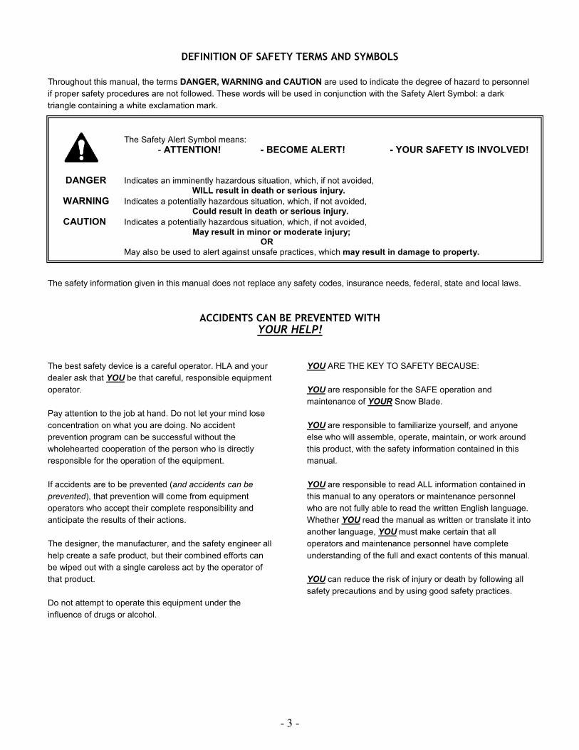
The Safety Alert Symbol means:
- ATTENTION! - BECOME ALERT! - YOUR SAFETY IS INVOLVED!
DANGER Indicates an imminently hazardous situation, which, if not avoided, WILL result in death or serious injury.
WARNING Indicates a potentially hazardous situation, which, if not avoided, Could result in death or serious injury.
CAUTION Indicates a potentially hazardous situation, which, if not avoided,
May result in minor or moderate injury; OR
May also be used to alert against unsafe practices, which may result in damage to property.
DEFINITION OF SAFETY TERMS AND SYMBOLS
Throughout this manual, the terms DANGER, WARNING and CAUTION are used to indicate the degree of hazard to personnel
if proper safety procedures are not followed. These words will be used in conjunction with the Safety Alert Symbol: a dark
triangle containing a white exclamation mark.
The safety information given in this manual does not replace any safety codes, insurance needs, federal, state and local laws.
ACCIDENTS CAN BE PREVENTED WITH
YOUR HELP!
The best safety device is a careful operator. HLA and your
dealer ask that YOU be that careful, responsible equipment
operator.
Pay attention to the job at hand. Do not let your mind lose
concentration on what you are doing. No accident
prevention program can be successful without the
wholehearted cooperation of the person who is directly
responsible for the operation of the equipment.
If accidents are to be prevented (and accidents can be
prevented), that prevention will come from equipment
operators who accept their complete responsibility and
anticipate the results of their actions.
The designer, the manufacturer, and the safety engineer all
help create a safe product, but their combined efforts can
be wiped out with a single careless act by the operator of
that product.
Do not attempt to operate this equipment under the
influence of drugs or alcohol.
YOU ARE THE KEY TO SAFETY BECAUSE:
YOU are responsible for the SAFE operation and
maintenance of YOUR Snow Blade.
YOU are responsible to familiarize yourself, and anyone
else who will assemble, operate, maintain, or work around
this product, with the safety information contained in this
manual.
YOU are responsible to read ALL information contained in
this manual to any operators or maintenance personnel
who are not fully able to read the written English language.
Whether YOU read the manual as written or translate it into
another language, YOU must make certain that all
operators and maintenance personnel have complete
understanding of the full and exact contents of this manual.
YOU can reduce the risk of injury or death by following all
safety precautions and by using good safety practices.
- 4 -
SAFETY INSTRUCTIONS
WORK SAFELY – A CAREFUL OPERATOR IS THE BEST INSURANCE AGAINST ACCIDENTS!!
SECTION 1 WARNING SECTION
• READ AND COMPLETELY UNDERSTAND THIS
MANUAL.
• READ AND COMPLETELY UNDERSTAND THE
MANUALS PROVIDED WITH YOUR POWER UNIT,
LOADER AND QUICK-ATTACH.
• Read and understand all safety signs on this product
and on your power unit, loader and quick-attach.
• Know all your controls and know how to quickly stop all
power unit movements, the Snow Blade movement,
and the engine in case of emergency.
• Know and obey all applicable government rules,
O.S.H.A regulations, local laws and other professional
guidelines for your operation.
• Make sure that anyone who will be assembling,
mounting, maintaining, repairing, removing and/or
storing this product:
� Has been instructed in the safe operation of this
product and of the power unit and the quick-attach
to which this product is attached.
� Is physically and mentally capable of the safe
operation of this type of equipment.
� Is not under the influence of drugs or alcohol.
� Is carefully supervised from a safe distance,
especially if such person is inexperienced.
� Wears personal protective equipment (i.e.
hardhat, safety glasses, work gloves, protective
shoes, respirator, ear protection, etc.)
� Does not wear loose fitting clothes, loose or
uncovered hair or any accessories (jewelry,
necktie, scarf, wrist watch, etc.) that can catch and
entangle on moving parts.
� Has annually reviewed all safety instructions.
• Know and follow good work practices when
assembling, mounting, maintaining, repairing,
removing and storing this product:
� Work on a level surface in a well lit area.
� Keep the area clean and dry.
� Use properly grounded electrical outlets and tools.
� Use the right tool for the job at hand.
� Make sure that your tools are in good condition for
performing the desired function.
� When using tools, wear the protective equipment
specified by the tool manufacturer (i.e. hardhat,
safety glasses, work gloves, protective shoes, etc.).
• Before leaving the operator’s station or before
beginning any type of work on this product, lower this
product to the ground, apply your power unit’s parking
brake, stop the engine, remove the starter key, wait for
all moving parts to stop and then relieve all pressure in
the hydraulic lines. Refer to your power unit’s
operator’s manual for instructions on how to relieve
hydraulic pressure in lines.
• Know your loader’s safe lifting and operating capacity
and the weight of this product. See the specifications
in this manual for the weight of this product and refer
to your power unit’s and loader’s operator’s manuals
for safe operating limits. Lift capacity may be reduced
if using a quick-attach.
• Never allow anyone, except the operator, to be around
the power unit or this product when either is in motion.
• Do not start up unless others are clear of the work
area.
• Do not allow riders on this product or the power unit.
• Do not stand or climb on this product when raised.
• Do not place any part of your body under any part of
this product unless this product is securely resting on
adequate blocking or on the ground.
• Do not use blocking made of concrete blocks, logs,
buckets, barrels or any other material that could
suddenly collapse or shift positions. Do not use wood
or steel blocking that shows any signs of material
decay. Do not use wood blocking that is warped,
twisted or tapered.
• Never operate controls from the ground. Operate the
controls only from the operator’s station.
• Never leave the equipment unattended with the engine
running or with this product raised on the loader.
• Be aware of the added weight and width of this
product. Reduce travel speeds accordingly, especially
when traveling over rough ground.
• Never lift this product above (a.) the operator’s eye
level or (b.) to a height where visibility is obstructed,
whichever is lower.
• Keep this product close to the ground and under
control when transporting.
BEFORE ATTEMPTING ANY TYPE OF ASSEMBLY, OPERATION, MAINTENANCE OR OTHER WORK ON OR NEAR THIS PRODUCT:
WHEN YOUR POWER UNIT IS USED DURING ANY TYPE OF ASSEMBLY, OPERATION, MAINTENANCE OR OTHER WORK ON OR NEAR THIS PRODUCT:
WARNING Obey all safety instructions listed in this section and throughout this manual. Failure to obey instructions in this section could result in death or serious injury.

- 5 -
SAFETY INSTRUCTIONS
WORK SAFELY – A CAREFUL OPERATOR IS THE BEST INSURANCE AGAINST ACCIDENTS!!
WARNING SECTION [Continued]
• Hydraulic fluid under pressure can penetrate the skin
and cause serious injury or death. Hydraulic leaks
under pressure may not be visible!
• If any fluid penetrates the skin, GET IMMEDIATE
MEDICAL ATTENTION!!
• Wear safety glasses, protective clothing and use a
sound piece of cardboard or wood when searching for
hydraulic leaks. DO NOT USE YOUR HANDS!
• Before connecting or disconnecting hydraulic hoses,
read your tractor or power unit’s operator’s manual for
detailed instructions on connecting and disconnecting
hydraulic attachments.
• Make certain that all parts meet the specifications for
this product when installing or replacing hydraulic
hoses or fittings.
• After connecting hydraulic lines:
� Slowly and carefully raise the loader and cycle the
rollback / dump cylinders to check hose
clearances and to check for any interference.
� Operate the hydraulics on this product to check
hose clearances and to check for any
interference.
� Make certain that the hoses cannot interfere with
or actuate the quick-attach mechanism.
� Make certain that hoses will not be pinched, or get
tangled, in any equipment.
• Do not lock the auxiliary hydraulics of your power unit
in the “ON” position.
• Refer to your power unit’s operator’s manual and this
manual for procedures and intervals, then inspect and
maintain the entire hydraulic system to insure that the
fluid remains cleans, that all devices function properly
and that there are no fluid leaks.
• Refer to the operator’s manuals of your power unit,
your loader and your quick-attach for special or
detailed mounting instructions.
• This product should fit onto the quick-attach or loader
arms of your power unit the same as the original
products that were designed by your loader / quick-
attach manufacturer.
• If this product does not fit properly, contact HLA before
operating.
• Never place your finger into the mounting plate or
loader holes. A slight movement of the power unit or
this product could cause serious injury.
• Make certain that all safety signs are in place and
legible. Refer to the safety sign page in this manual for
the placement of safety signs for this product.
• Replace all damaged or excessively worn parts and
hardware only with genuine HLA parts or with properly
rated fasteners, hydraulic hoses or fittings.
• Make certain that all locking pins, latches and
connection devices are properly installed and secured.
• Make certain that all protective guards, canopies,
doors, etc. are in place and secure.
• Do not exceed 15 MPH/24 KPH when operating.
• Make no modifications to your Snow Blade.
• When making repairs, use only genuine HLA parts or,
for fasteners, hydraulic hoses or hydraulic fittings, use
only properly rated parts.
• Replacement parts, for parts with safety signs
attached, must also have safety sign attached.
Think SAFETY! Work SAFELY!
BEFORE EACH USE, THOROUGHLY INSPECT THIS PRODUCT AND:
WHEN OPERATING THIS PRODUCT IN ACCORDANCE WITH DESIGN INTENTIONS:
WHEN MOUNTING THIS PRODUCT TO YOUR POWER UNIT:
WHEN ADJUSTING, SERVICING OR REPAIRING THIS PRODUCT:
WARNING Obey all safety instructions listed in this section and throughout this manual. Failure to obey instructions in this section
could result in death or serious injury.
WHEN DEALING WITH HYDRAULICS DURING ANY TYPE OF ASSEMBLY, OPERATION, MAINTENANCE OR OTHER WORK ON OR NEAR THIS PRODUCT:
- 6 -
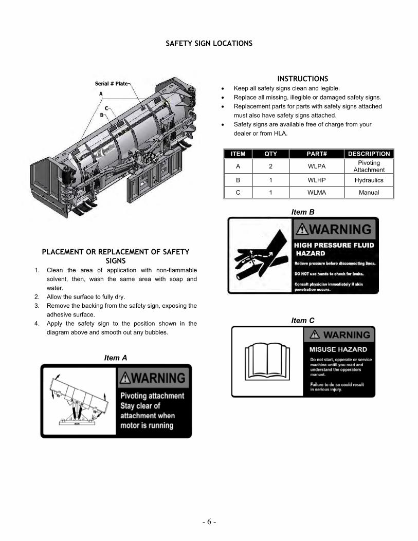
SAFETY SIGN LOCATIONS
PLACEMENT OR REPLACEMENT OF SAFETY
SIGNS
1. Clean the area of application with non-flammable
solvent, then, wash the same area with soap and
water.
2. Allow the surface to fully dry.
3. Remove the backing from the safety sign, exposing the
adhesive surface.
4. Apply the safety sign to the position shown in the
diagram above and smooth out any bubbles.
Item A
INSTRUCTIONS
• Keep all safety signs clean and legible.
• Replace all missing, illegible or damaged safety signs.
• Replacement parts for parts with safety signs attached
must also have safety signs attached.
• Safety signs are available free of charge from your
dealer or from HLA.
Item B
Item C
ITEM QTY PART# DESCRIPTION
A 2 WLPA Pivoting
Attachment
B 1 WLHP Hydraulics
C 1 WLMA Manual

POWER UNIT SPECIFICATIONS
IMPORTANT Exceeding any of the recommended power unit specifications
• CAN result in damage to your power unit and/or this product and
• WILL void all HLA warranties.
ATTACHMENT SPECIFICATIONS
3000W Series
PART # NAME APPROX. WEIGHT LBS.
CLEARING WIDTH CLOSED
CLEARING WIDTH OPEN
ROAD CLEARANCE ANGLED INCHES
SB3200W611 SnowWing 3200 SERIES 6ft 1300 6ft 11ft 70
SB3200W712 SnowWing 3200 SERIES 7ft 1360 7ft 12ft 80
SB3200W813 SnowWing 3200 SERIES 8ft 1420 8ft 13ft 90
SB3200W914 SnowWing 3200 SERIES 9ft 1480 9ft 14ft 100
SNOW BLADE MOUNTING
1. Place this product on a firm, level surface that is large enough to safely accommodate this product, your power unit and all
workers involved in the mounting process.
2. Be sure all connection points are properly secured.
3. Refer to the operator’s manual(s) for your power unit, loader and quick-attach and follow the mounting instructions
contained therein.
IMPORTANT Lubricate all grease fittings before connecting this product to your power unit’s hydraulic system.
Refer to SNOW BLADE MAINTENANCE (page10) and follow instructions
LOADER DESCRIPTION
50-85 HP
Gross Machine Weight - 10,000 lb. Max.
SAFETY FIRST!! READ AND UNDERSTAND THE SAFETY INSTRUCTIONS (pages 3-6 of
this manual) BEFORE BEGINNING ANY SNOW BLADE MOUNTING.
- 8 -
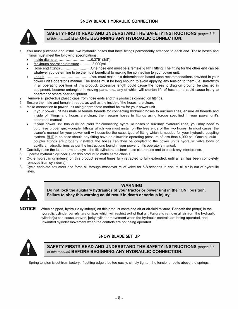
SNOW BLADE HYDRAULIC CONNECTION
1. You must purchase and install two hydraulic hoses that have fittings permanently attached to each end. These hoses and
fittings must meet the following specifications:
• Inside diameter ……………………….0.375” (3/8”)
• Maximum operating pressure ………..3,000psi.
• Hose end fittings ………………..……One hose end must be a female ½ NPT fitting. The fitting for the other end can be
whatever you determine to be the most beneficial to making the connection to your power unit.
• Length …………………………………You must make this determination based upon recommendations provided in your
power unit’s operator’s manual. The hoses must be long enough to avoid applying any tension to them (i.e. stretching)
in all operating positions of this product. Excessive length could cause the hoses to drag on ground, be pinched in
equipment, become entangled in moving parts, etc., any of which will shorten life of hoses and could cause injury to
operator or others near equipment.
2. Remove all protective plastic caps from hose ends and this product’s connection fittings.
3. Ensure the male and female threads, as well as the inside of the hoses, are clean.
4. Make connection to power unit using appropriate method below for your power unit.
• If your power unit has male or female threads for connecting hydraulic hoses to auxiliary lines, ensure all threads and
inside of fittings and hoses are clean; then secure hoses to fittings using torque specified in your power unit’s
operator’s manual.
• If your power unit has quick-couplers for connecting hydraulic hoses to auxiliary hydraulic lines, you may need to
purchase proper quick-coupler fittings which you must install on the free ends of the two hoses. In most cases, the
owner’s manual for your power unit will describe the exact type of fitting which is needed for your hydraulic coupling
system. BUT in no case should any fitting have an allowable operating pressure of less than 4,000 psi. Once all quick-
coupler fittings are properly installed, the hoses can then be coupled to the power unit’s hydraulic valve body or
auxiliary hydraulic lines as per the instructions found in your power unit’s operator’s manual.
5. Carefully raise the loader arm and cycle the tilt cylinders to check hose clearances and to check any interference.
6. Operate hydraulic cylinder(s) on this product to make same checks.
7. Cycle hydraulic cylinder(s) on this product several times fully retracted to fully extended, until all air has been completely
removed from cylinder(s).
8. Cycle endplate actuators and force oil through crossover relief valve for 5-8 seconds to ensure all air is out of hydraulic
lines.
NOTICE When shipped, hydraulic cylinder(s) on this product contained air or air-fluid mixture. Beneath the port(s) in the
hydraulic cylinder barrels, are orifices which will restrict exit of that air. Failure to remove all air from the hydraulic
cylinder(s) can cause uneven, jerky cylinder movement when the hydraulic controls are being operated, and
unwanted cylinder movement when the controls are not being operated.
SNOW BLADE SET UP
Spring tension is set from factory. If cutting edge trips too easily, simply tighten the tensioner bolts above the springs.
SAFETY FIRST!! READ AND UNDERSTAND THE SAFETY INSTRUCTIONS (pages 3-6 of this manual) BEFORE BEGINNING ANY HYDRAULIC CONNECTION.
WARNING
Do not lock the auxiliary hydraulics of your tractor or power unit in the “ON” position.
Failure to obey this warning could result in death or serious injury.
SAFETY FIRST!! READ AND UNDERSTAND THE SAFETY INSTRUCTIONS (pages 3-6 of this manual) BEFORE BEGINNING ANY HYDRAULIC CONNECTION.
- 9 -
SNOW BLADE OPERATION
SAFETY FIRST!! READ AND UNDERSTAND THE SAFETY INSTRUCTIONS (pages 3-6 of
this manual) BEFORE BEGINNING ANY SNOW BLADE OPERATION.
WARNING Failure to obey the following procedures could result in death or serious injury.
• Never lift this product above the operator’s eye level OR to a height where visibility is obstructed, whichever is lower.
• Do not exceed 15 miles per hour while operating.
IMPORTANT Striking solid objects hidden in snow OR pushing materials other than snow
• CAN result in damage to this product and
• WILL void all HLA warranties.
Before any snowfall, inspect site where your Snow Blade is to be used. Locate any obstructions (i.e. curbs, sidewalks, parking
bumpers, pipes, shrubs, fences, etc.) and any variations in elevation (i.e. retaining walls, slopes, holes, etc.), in order to avoid
these elements during the snow plowing operation.
_________________________________________________________________________________________________
__________________________________________________________________________________
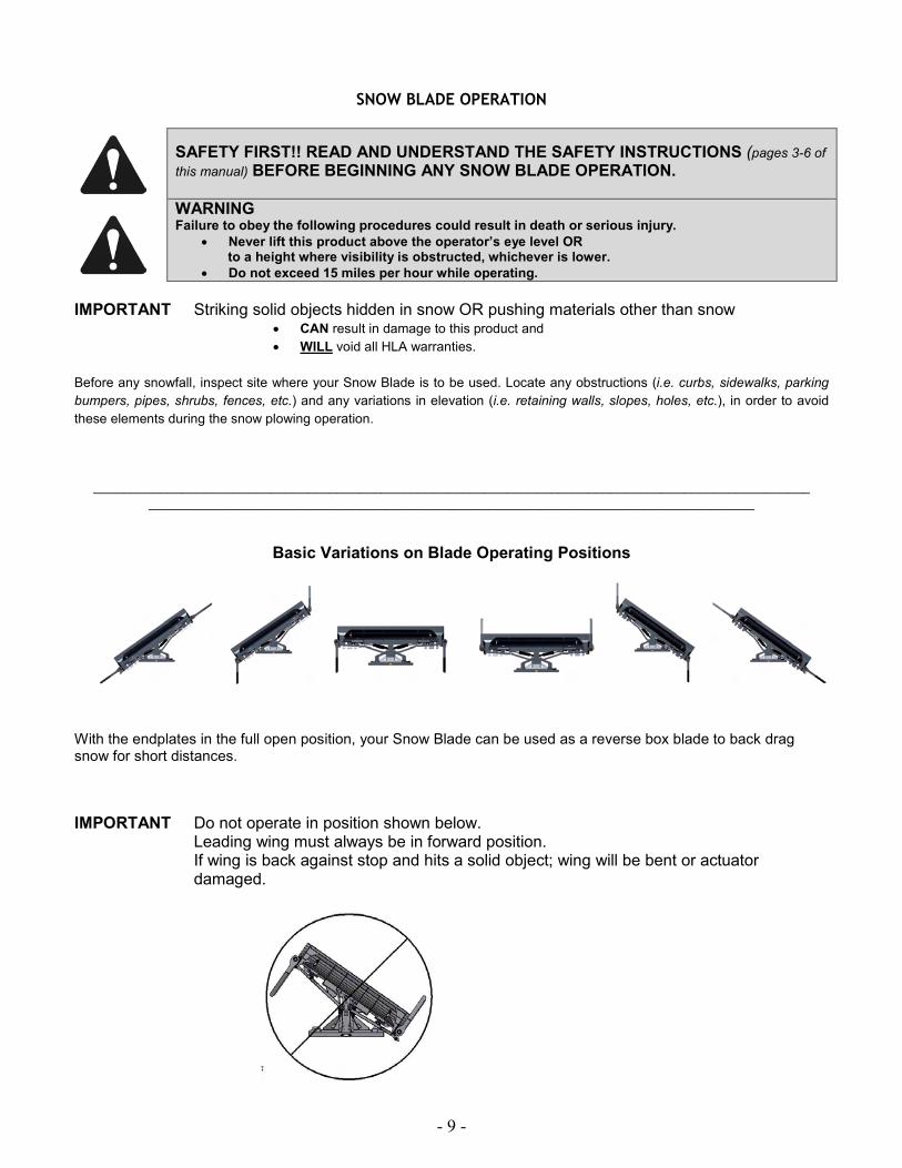
Basic Variations on Blade Operating Positions
With the endplates in the full open position, your Snow Blade can be used as a reverse box blade to back drag snow for short distances.
IMPORTANT Do not operate in position shown below. Leading wing must always be in forward position. If wing is back against stop and hits a solid object; wing will be bent or actuator
damaged.
- 10 -
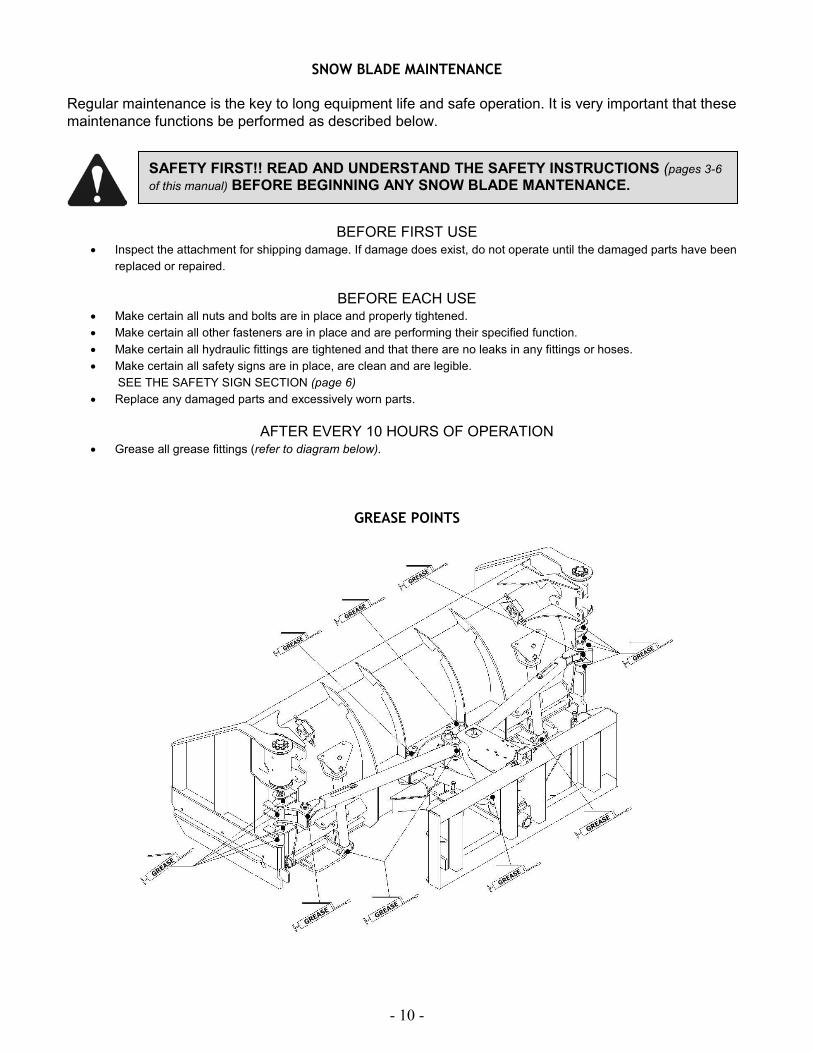
SNOW BLADE MAINTENANCE
Regular maintenance is the key to long equipment life and safe operation. It is very important that these
maintenance functions be performed as described below.
BEFORE FIRST USE
• Inspect the attachment for shipping damage. If damage does exist, do not operate until the damaged parts have been
replaced or repaired.
BEFORE EACH USE • Make certain all nuts and bolts are in place and properly tightened.
• Make certain all other fasteners are in place and are performing their specified function.
• Make certain all hydraulic fittings are tightened and that there are no leaks in any fittings or hoses.
• Make certain all safety signs are in place, are clean and are legible.
SEE THE SAFETY SIGN SECTION (page 6)
• Replace any damaged parts and excessively worn parts.
AFTER EVERY 10 HOURS OF OPERATION
• Grease all grease fittings (refer to diagram below).
GREASE POINTS
SAFETY FIRST!! READ AND UNDERSTAND THE SAFETY INSTRUCTIONS (pages 3-6 of this manual) BEFORE BEGINNING ANY SNOW BLADE MANTENANCE.

- 11 -
SNOW BLADE SERVICE
REPLACEMENT OF WEAR EDGE
1. Park power unit on level surface with this product properly attached.
2. Place power unit’s transmission in ”Park” and engage the parking brake.
3. Lower this product onto blocking positioned immediately behind moldboard. This blocking must be of sufficient height to
hold wear edge approximately 6” to 8” above the level surface.
4. Shut off power unit’s engine, set parking brake, remove starter key, wait for all moving parts to come to a stop and
relieve hydraulic pressure. Refer to your power unit’s manual for instruction on how to relieve hydraulic pressure in
lines.
5. Loosen and remove nuts on all wear edge bolts except the bolts on each end of wear edge.
6. While holding up end of wear edge, remove nut and bolt from that end and allow it to pivot down to the level surface.
7. Repeat step 6 for other end of wear edge.
8. Properly dispose of wear edge and all bolts and nuts.
9. Reinstall new wear edge by reversing procedures in steps 7 through 5 and tightening the nuts to 75 ft. lbs.
WARNING Hydraulic fluid under pressure can penetrate skin, resulting in serious injury or death.
Always relieve hydraulic pressure before disconnecting lines.
SAFETY FIRST!! READ AND UNDERSTAND THE SAFETY INSTRUCTIONS (pages 3-6
of this manual) BEFORE BEGINNING ANY SNOW BLADE SERVICE.

Parts List
ITEM QTY PART# DESCRIPTION
12 16 LA-SB1022 1/2" Lock Nut
24 2 LA-L2082E SB3200 SnowWing Actuator
25 1 LP-100065 Right Endplate Assembly
26 2 LP-100066 SB3200 SnowWing Endplate Cutting Edge
27 1 LP-100064 Left Endplate Assembly
28 8 11-1564 3/4" Locking nut
29 2 11-1577 1" x 8" Hex Head Bolt
30 16 11-1578 3/8"-16 x 1" L9 Bowman Bolt
31 2 LP-100067 SB3200W Endplate Pivot Pin
38 8 11-1567 3/4" x 3 Bolt
39 2 LP-100068 SB3200 WingBlade Endplate Float Spring
42 6 LA-SB1139 SB4000 Endplate Wearbar Spacer
43 6 11-1568 1/2" x 2-1/4" Carriage Bolt
44 2 11-1562 1" Lock Nut
45 16 LP-100069 SB3200W Actuator Bolt Bushing
SB3200 SnowWing Endplate
- 12 -
27
29
30
45
31
24
44
26
39
43
42
12
25
38 28
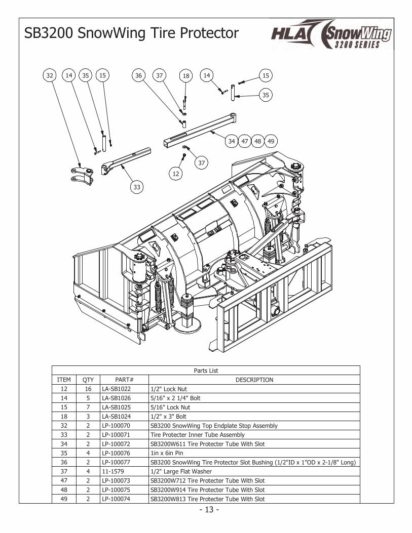
Parts List
ITEM QTY PART# DESCRIPTION
12 16 LA-SB1022 1/2" Lock Nut
14 5 LA-SB1026 5/16" x 2 1/4" Bolt
15 7 LA-SB1025 5/16" Lock Nut
18 3 LA-SB1024 1/2" x 3" Bolt
32 2 LP-100070 SB3200 SnowWing Top Endplate Stop Assembly
33 2 LP-100071 Tire Protecter Inner Tube Assembly
34 2 LP-100072 SB3200W611 Tire Protecter Tube With Slot
35 4 LP-100076 1in x 6in Pin
36 2 LP-100077 SB3200 SnowWing Tire Protector Slot Bushing (1/2"ID x 1"OD x 2-1/8" Long)
37 4 11-1579 1/2" Large Flat Washer
47 2 LP-100073 SB3200W712 Tire Protecter Tube With Slot
48 2 LP-100075 SB3200W914 Tire Protecter Tube With Slot
49 2 LP-100074 SB3200W813 Tire Protecter Tube With Slot
SB3200 SnowWing Tire Protector
- 13 -
32 3514 15 183736 14
35
15
34 47 48 49
37
12
33
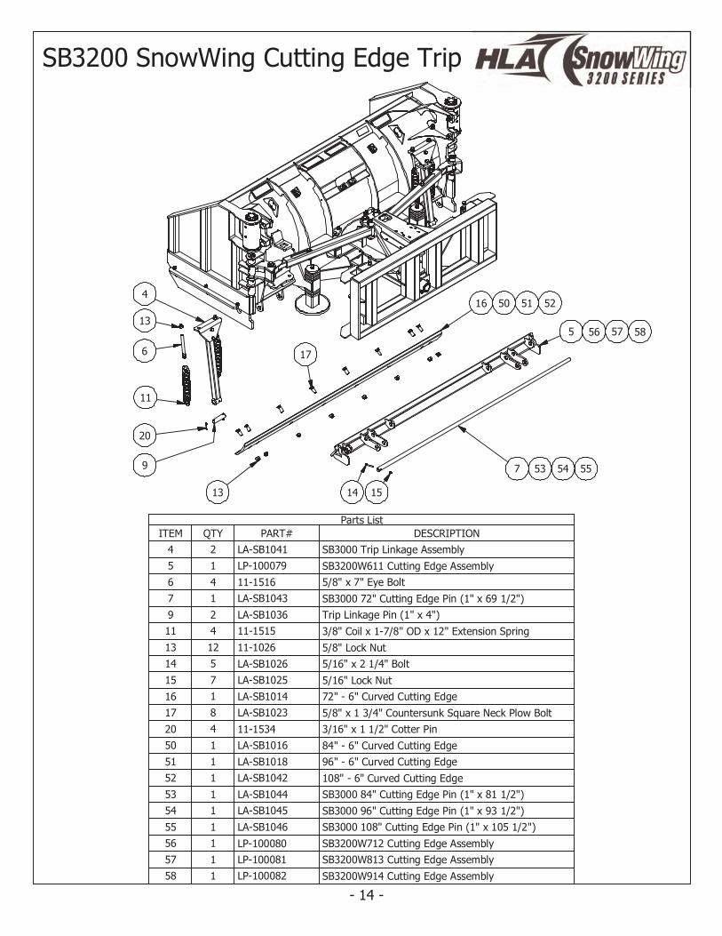
Parts List
ITEM QTY PART# DESCRIPTION
4 2 LA-SB1041 SB3000 Trip Linkage Assembly
5 1 LP-100079 SB3200W611 Cutting Edge Assembly
6 4 11-1516 5/8" x 7" Eye Bolt
7 1 LA-SB1043 SB3000 72" Cutting Edge Pin (1" x 69 1/2")
9 2 LA-SB1036 Trip Linkage Pin (1" x 4")
11 4 11-1515 3/8" Coil x 1-7/8" OD x 12" Extension Spring
13 12 11-1026 5/8" Lock Nut
14 5 LA-SB1026 5/16" x 2 1/4" Bolt
15 7 LA-SB1025 5/16" Lock Nut
16 1 LA-SB1014 72" - 6" Curved Cutting Edge
17 8 LA-SB1023 5/8" x 1 3/4" Countersunk Square Neck Plow Bolt
20 4 11-1534 3/16" x 1 1/2" Cotter Pin
50 1 LA-SB1016 84" - 6" Curved Cutting Edge
51 1 LA-SB1018 96" - 6" Curved Cutting Edge
52 1 LA-SB1042 108" - 6" Curved Cutting Edge
53 1 LA-SB1044 SB3000 84" Cutting Edge Pin (1" x 81 1/2")
54 1 LA-SB1045 SB3000 96" Cutting Edge Pin (1" x 93 1/2")
55 1 LA-SB1046 SB3000 108" Cutting Edge Pin (1" x 105 1/2")
56 1 LP-100080 SB3200W712 Cutting Edge Assembly
57 1 LP-100081 SB3200W813 Cutting Edge Assembly
58 1 LP-100082 SB3200W914 Cutting Edge Assembly
SB3200 SnowWing Cutting Edge Trip
- 14 -
11
6
13
20
9
16 50 51 52
17
13
5 56 57 58
14 15
7 53 54 55
4
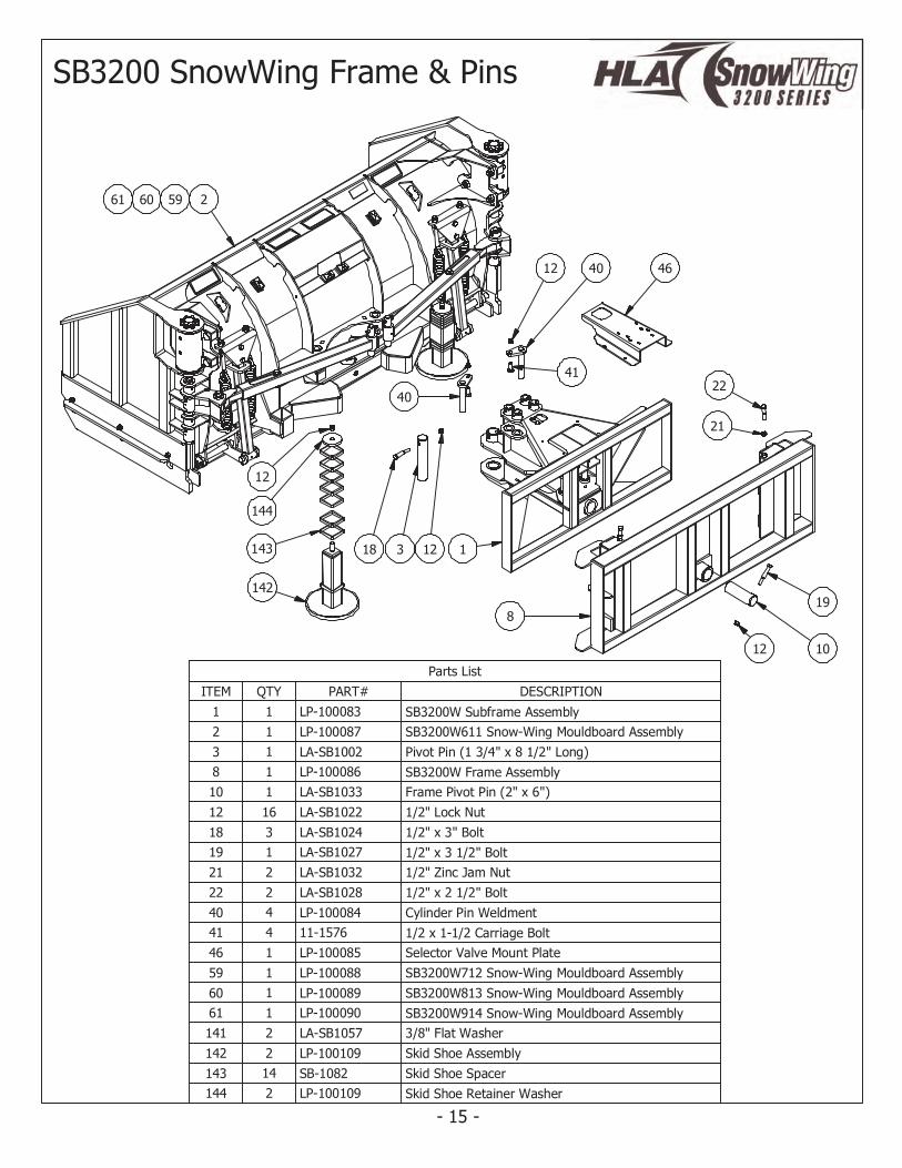
Parts List
ITEM QTY PART# DESCRIPTION
1 1 LP-100083 SB3200W Subframe Assembly
2 1 LP-100087 SB3200W611 Snow-Wing Mouldboard Assembly
3 1 LA-SB1002 Pivot Pin (1 3/4" x 8 1/2" Long)
8 1 LP-100086 SB3200W Frame Assembly
10 1 LA-SB1033 Frame Pivot Pin (2" x 6")
12 16 LA-SB1022 1/2" Lock Nut
18 3 LA-SB1024 1/2" x 3" Bolt
19 1 LA-SB1027 1/2" x 3 1/2" Bolt
21 2 LA-SB1032 1/2" Zinc Jam Nut
22 2 LA-SB1028 1/2" x 2 1/2" Bolt
40 4 LP-100084 Cylinder Pin Weldment
41 4 11-1576 1/2 x 1-1/2 Carriage Bolt
46 1 LP-100085 Selector Valve Mount Plate
59 1 LP-100088 SB3200W712 Snow-Wing Mouldboard Assembly
60 1 LP-100089 SB3200W813 Snow-Wing Mouldboard Assembly
61 1 LP-100090 SB3200W914 Snow-Wing Mouldboard Assembly
141 2 LA-SB1057 3/8" Flat Washer
142 2 LP-100109 Skid Shoe Assembly
143 14 SB-1082 Skid Shoe Spacer
144 2 LP-100109 Skid Shoe Retainer Washer
SB3200 SnowWing Frame & Pins
- 15 -
46
22
21
318 12 1
4012
41
8
12 10
19
40
2596061
142
143
144
12
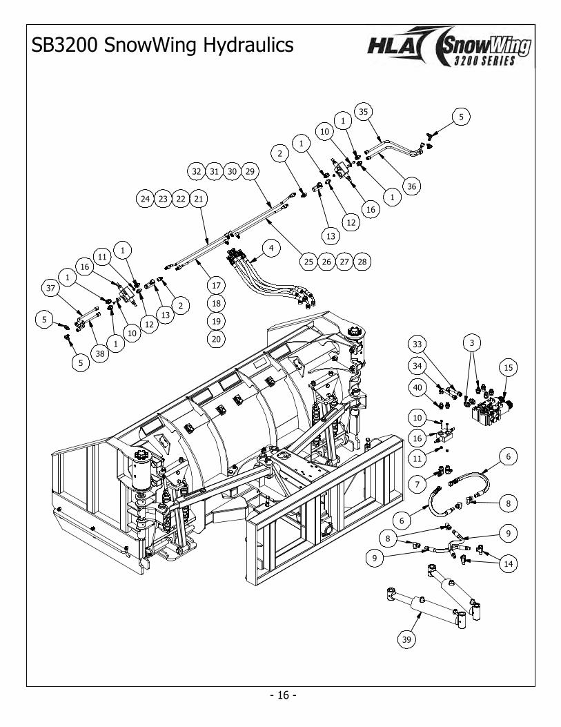
SB3200 SnowWing Hydraulics
- 16 -
355
36
1
1
10
16
1
12
13
29303132
2
25 26 27 28
4
21222324
17
18
19
20
213
1
12
11
16
10
1
1
38
37
5
5
39
8
149
9
6
6
8
7
11
16
15
333
34
40
10
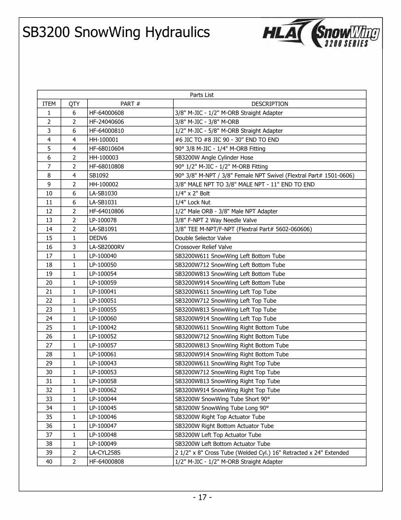
Parts List
ITEM QTY PART # DESCRIPTION
1 6 HF-64000608 3/8" M-JIC - 1/2" M-ORB Straight Adapter
2 2 HF-24040606 3/8" M-JIC - 3/8" M-ORB
3 6 HF-64000810 1/2" M-JIC - 5/8" M-ORB Straight Adapter
4 4 HH-100001 #6 JIC TO #8 JIC 90 - 30" END TO END
5 4 HF-68010604 90° 3/8 M-JIC - 1/4" M-ORB Fitting
6 2 HH-100003 SB3200W Angle Cylinder Hose
7 2 HF-68010808 90° 1/2" M-JIC - 1/2" M-ORB Fitting
8 4 SB1092 90° 3/8" M-NPT / 3/8" Female NPT Swivel (Flextral Part# 1501-0606)
9 2 HH-100002 3/8" MALE NPT TO 3/8" MALE NPT - 11" END TO END
10 6 LA-SB1030 1/4" x 2" Bolt
11 6 LA-SB1031 1/4" Lock Nut
12 2 HF-64010806 1/2" Male ORB - 3/8" Male NPT Adapter
13 2 LP-100078 3/8" F-NPT 2 Way Needle Valve
14 2 LA-SB1091 3/8" TEE M-NPT/F-NPT (Flextral Part# 5602-060606)
15 1 DEDV6 Double Selector Valve
16 3 LA-SB2000RV Crossover Relief Valve
17 1 LP-100040 SB3200W611 SnowWing Left Bottom Tube
18 1 LP-100050 SB3200W712 SnowWing Left Bottom Tube
19 1 LP-100054 SB3200W813 SnowWing Left Bottom Tube
20 1 LP-100059 SB3200W914 SnowWing Left Bottom Tube
21 1 LP-100041 SB3200W611 SnowWing Left Top Tube
22 1 LP-100051 SB3200W712 SnowWing Left Top Tube
23 1 LP-100055 SB3200W813 SnowWing Left Top Tube
24 1 LP-100060 SB3200W914 SnowWing Left Top Tube
25 1 LP-100042 SB3200W611 SnowWing Right Bottom Tube
26 1 LP-100052 SB3200W712 SnowWing Right Bottom Tube
27 1 LP-100057 SB3200W813 SnowWing Right Bottom Tube
28 1 LP-100061 SB3200W914 SnowWing Right Bottom Tube
29 1 LP-100043 SB3200W611 SnowWing Right Top Tube
30 1 LP-100053 SB3200W712 SnowWing Right Top Tube
31 1 LP-100058 SB3200W813 SnowWing Right Top Tube
32 1 LP-100062 SB3200W914 SnowWing Right Top Tube
33 1 LP-100044 SB3200W SnowWing Tube Short 90°
34 1 LP-100045 SB3200W SnowWing Tube Long 90°
35 1 LP-100046 SB3200W Right Top Actuator Tube
36 1 LP-100047 SB3200W Right Bottom Actuator Tube
37 1 LP-100048 SB3200W Left Top Actuator Tube
38 1 LP-100049 SB3200W Left Bottom Actuator Tube
39 2 LA-CYL258S 2 1/2" x 8" Cross Tube (Welded Cyl.) 16" Retracted x 24" Extended
40 2 HF-64000808 1/2" M-JIC - 1/2" M-ORB Straight Adapter
SB3200 SnowWing Hydraulics
- 17 -

Please discard terminal protector.
Live Terminal #1Ground Terminal #2
Do not use middle terminal.
All hydraulic ports on diverter valve are #10 ORB.
AUXILARY OUTPUT (2nd FUNCTION)Activated when valve is switched on.
DEFAULT OUTPUT LINES(B1 & B2)Automatically on when valve is switched off .
INPUT LINES(from remotes) (A1 & A2)
Banked Diverter Valve Plumbing & Electrical Directions
Standard "switch bracket" to be mounted in operators station.
(Mount on joy stick if possible)
To 12 volt + ignition.
To Valve #2
ONOFF
AUXILARY OUTPUT (3rd FUNCTION)Activated when valve is switched on.
ON
To Valve #1
Ground
GroundValve #1Valve #2
14 ga.4 wire.(Use only 3 wires)
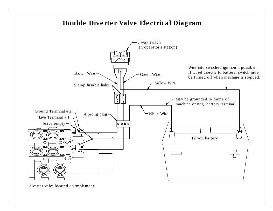
Double Diverter Valve Electrical Diagram
12 volt battery
3 way switch(In operator's station)
Live Terminal #1Ground Terminal #2
diverter valve located on implement
5 amp fusable links
4 prong plug
Wire into switched ignition if possible.If wired directly to battery, switch must be turned off when machine is stopped.
May be grounded to frame of machine or neg. battery terminal.
leave empty
Brown Wire Green Wire
Yellow Wire
White Wire
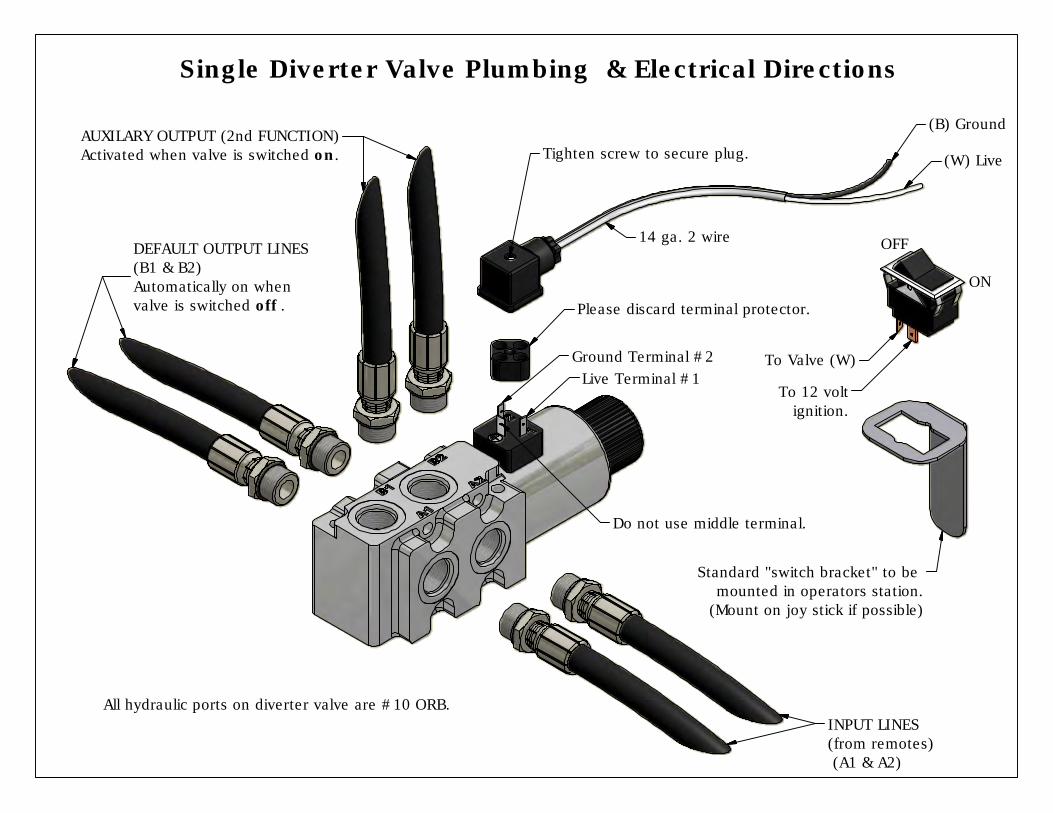
Please discard terminal protector.
(B) Ground
(W) Live
Live Terminal #1Ground Terminal #2
Do not use middle terminal.
All hydraulic ports on diverter valve are #10 ORB.
Tighten screw to secure plug.AUXILARY OUTPUT (2nd FUNCTION)Activated when valve is switched on.
DEFAULT OUTPUT LINES(B1 & B2)Automatically on when valve is switched off .
INPUT LINES(from remotes) (A1 & A2)
Single Diverter Valve Plumbing & Electrical Directions
Standard "switch bracket" to be mounted in operators station.
(Mount on joy stick if possible)
To 12 volt ignition.
To Valve (W)
ON
OFF14 ga. 2 wire
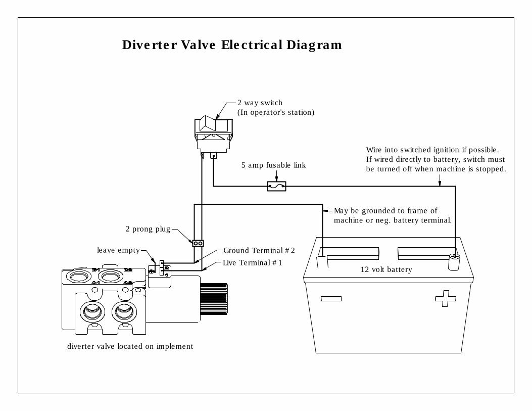
Diverter Valve Electrical Diagram
2 prong plug
5 amp fusable link
2 way switch(In operator's station)
12 volt battery
diverter valve located on implement
Ground Terminal #2Live Terminal #1
leave empty
Wire into switched ignition if possible.If wired directly to battery, switch must be turned off when machine is stopped.
May be grounded to frame of machine or neg. battery terminal.
- 18 -
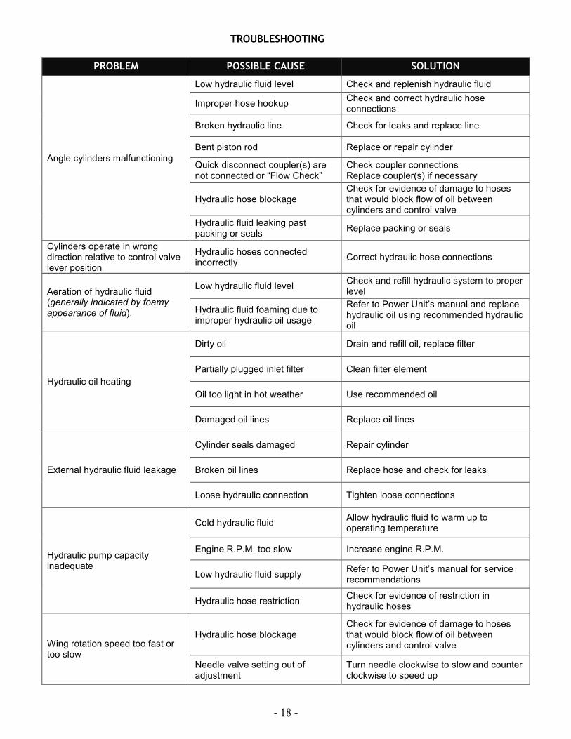
TROUBLESHOOTING
PROBLEM POSSIBLE CAUSE SOLUTION
Angle cylinders malfunctioning
Low hydraulic fluid level Check and replenish hydraulic fluid
Improper hose hookup Check and correct hydraulic hose connections
Broken hydraulic line Check for leaks and replace line
Bent piston rod Replace or repair cylinder
Quick disconnect coupler(s) are not connected or “Flow Check”
Check coupler connections Replace coupler(s) if necessary
Hydraulic hose blockage Check for evidence of damage to hoses that would block flow of oil between cylinders and control valve
Hydraulic fluid leaking past packing or seals
Replace packing or seals
Cylinders operate in wrong direction relative to control valve lever position
Hydraulic hoses connected incorrectly
Correct hydraulic hose connections
Aeration of hydraulic fluid (generally indicated by foamy appearance of fluid).
Low hydraulic fluid level Check and refill hydraulic system to proper level
Hydraulic fluid foaming due to improper hydraulic oil usage
Refer to Power Unit’s manual and replace hydraulic oil using recommended hydraulic oil
Hydraulic oil heating
Dirty oil Drain and refill oil, replace filter
Partially plugged inlet filter Clean filter element
Oil too light in hot weather Use recommended oil
Damaged oil lines Replace oil lines
External hydraulic fluid leakage
Cylinder seals damaged Repair cylinder
Broken oil lines Replace hose and check for leaks
Loose hydraulic connection Tighten loose connections
Hydraulic pump capacity inadequate
Cold hydraulic fluid Allow hydraulic fluid to warm up to operating temperature
Engine R.P.M. too slow Increase engine R.P.M.
Low hydraulic fluid supply Refer to Power Unit’s manual for service recommendations
Hydraulic hose restriction Check for evidence of restriction in hydraulic hoses
Wing rotation speed too fast or too slow
Hydraulic hose blockage Check for evidence of damage to hoses that would block flow of oil between cylinders and control valve
Needle valve setting out of adjustment
Turn needle clockwise to slow and counter clockwise to speed up
- 19 -
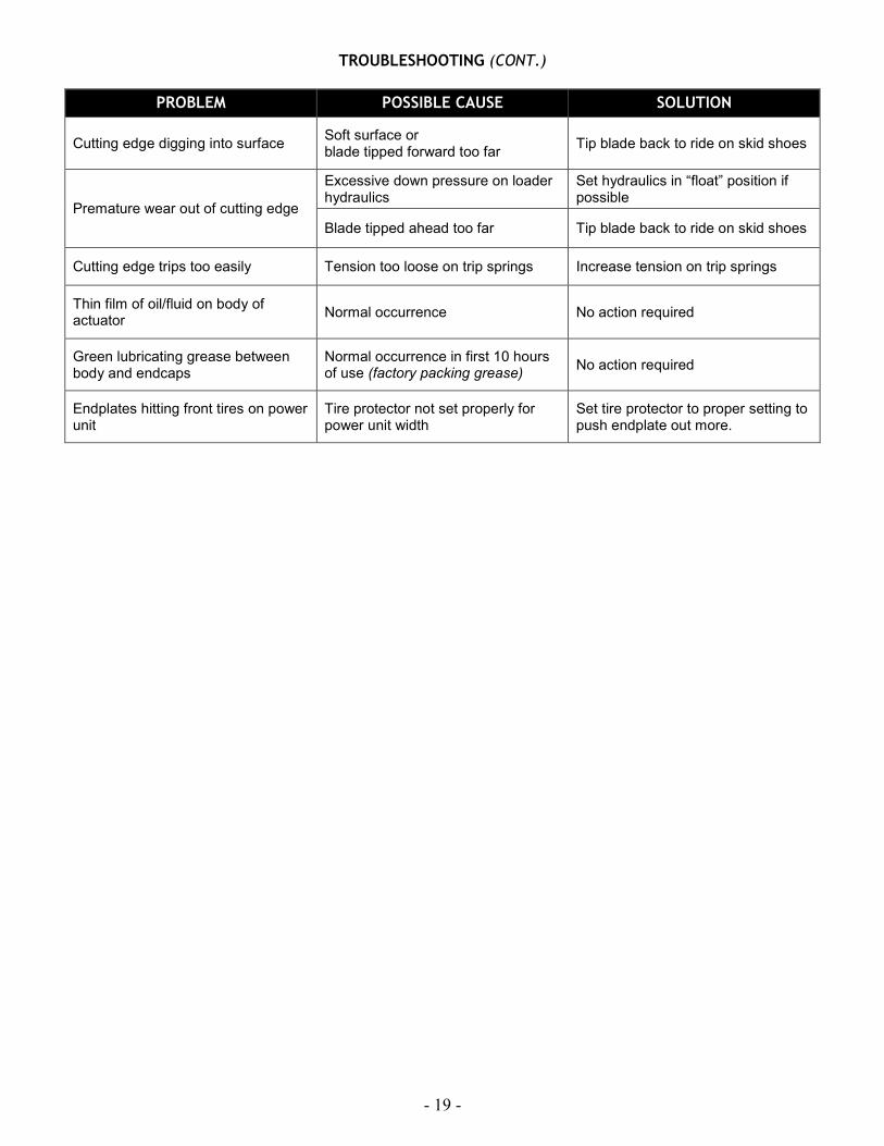
TROUBLESHOOTING (CONT.)
PROBLEM POSSIBLE CAUSE SOLUTION
Cutting edge digging into surface Soft surface or blade tipped forward too far
Tip blade back to ride on skid shoes
Premature wear out of cutting edge
Excessive down pressure on loader hydraulics
Set hydraulics in “float” position if possible
Blade tipped ahead too far Tip blade back to ride on skid shoes
Cutting edge trips too easily Tension too loose on trip springs Increase tension on trip springs
Thin film of oil/fluid on body of actuator
Normal occurrence No action required
Green lubricating grease between body and endcaps
Normal occurrence in first 10 hours of use (factory packing grease)
No action required
Endplates hitting front tires on power unit
Tire protector not set properly for power unit width
Set tire protector to proper setting to push endplate out more.

- 20 -
Horst Welding Warranty Policy
All equipment is sold subject to mutual agreement that it is warranted by the
company to be free from defects of material and workmanship. But the
company shall not be liable for special, indirect, or consequential damages
of any kind under this contract or otherwise. The company’s liability shall be
limited exclusively to replacing or repairing without charge, at its factory or
elsewhere, at its discretion, any material or workmanship defects that
become apparent within one year from the date on which the equipment
was purchased. The company shall have no liability for related damages of
any kind. The buyer by the acceptance of the equipment will assume all
liability for any damages that may result from the use or misuse by his
employees or others.
Distributor/dealer must notify Horst Welding of the defect by phone, fax or
email. Recommended repairs and cost are to be discussed with, and
agreed on, by an authorized Horst Welding representative. Repair and labor
(at an agreed rate) will be performed by a dealer for Horst Welding or a
repair shop designated by Horst Welding.
All claims must be discussed with a representative of Horst Welding prior to
any repairs or warranty will be void.
All claims must be accompanied by a photograph of the defective product.
All defective products must be returned to Horst Welding in Listowel, Ontario
unless directed otherwise by a representative of Horst Welding.
Horst Welding Warranty will not apply to:
• Product that in the judgment of Horst Welding has been misused by
the user.
• Product not sold or manufactured by Horst Welding.
• Alterations or repairs not authorized by a representative of Horst
Welding.
1-866-567-4162 www.horstwelding.com 8082 Rd 129 Listowel, ON, N4W 3G8, Canada