Embed Size (px)
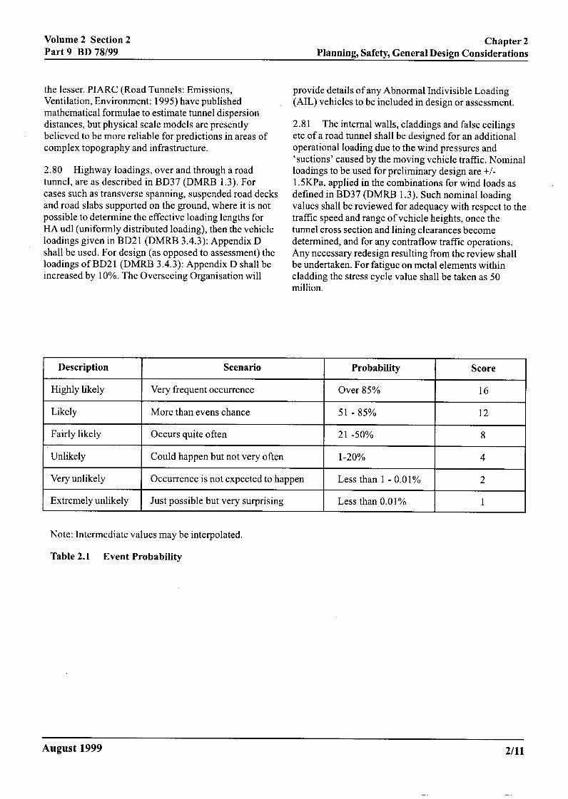
DESCRIPTION
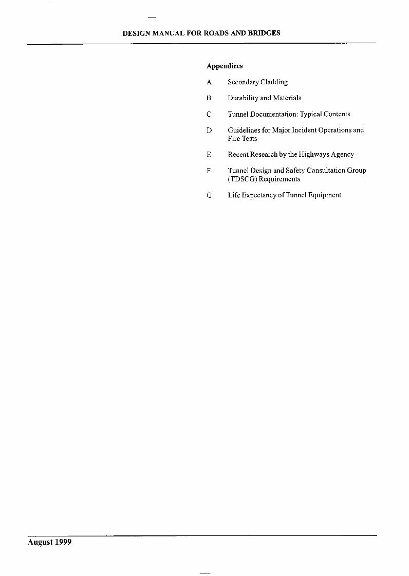
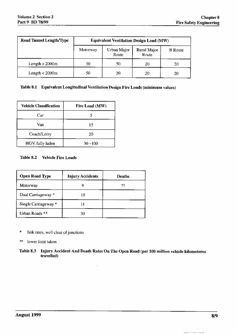
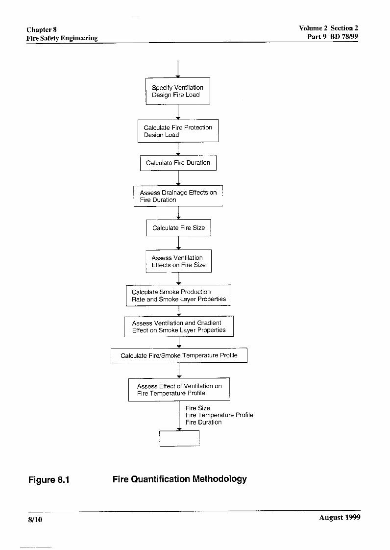
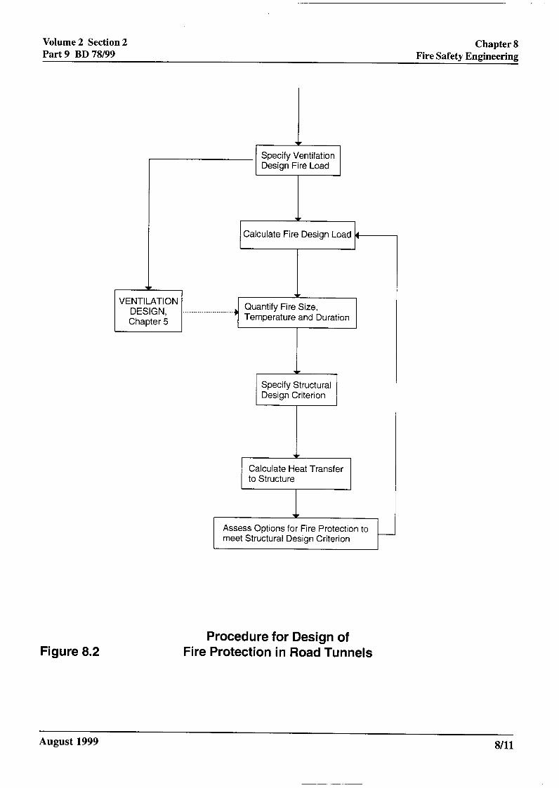
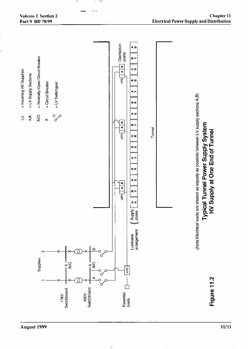
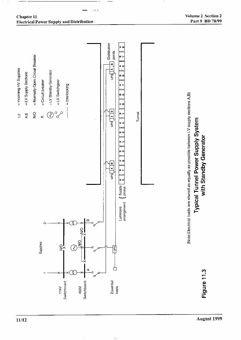
Road tunnel manual
Citation preview
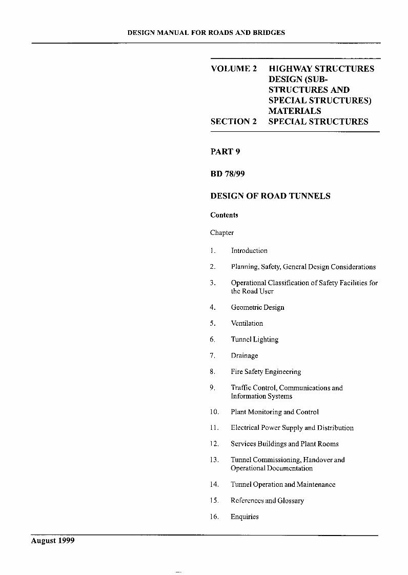
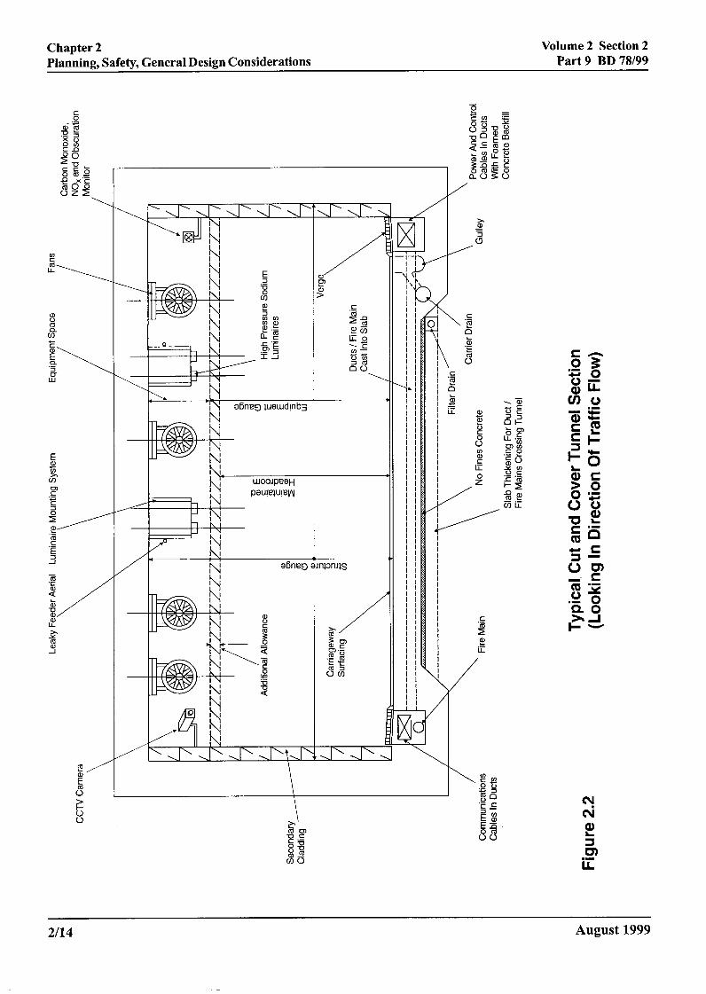
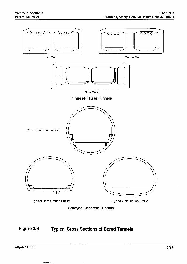
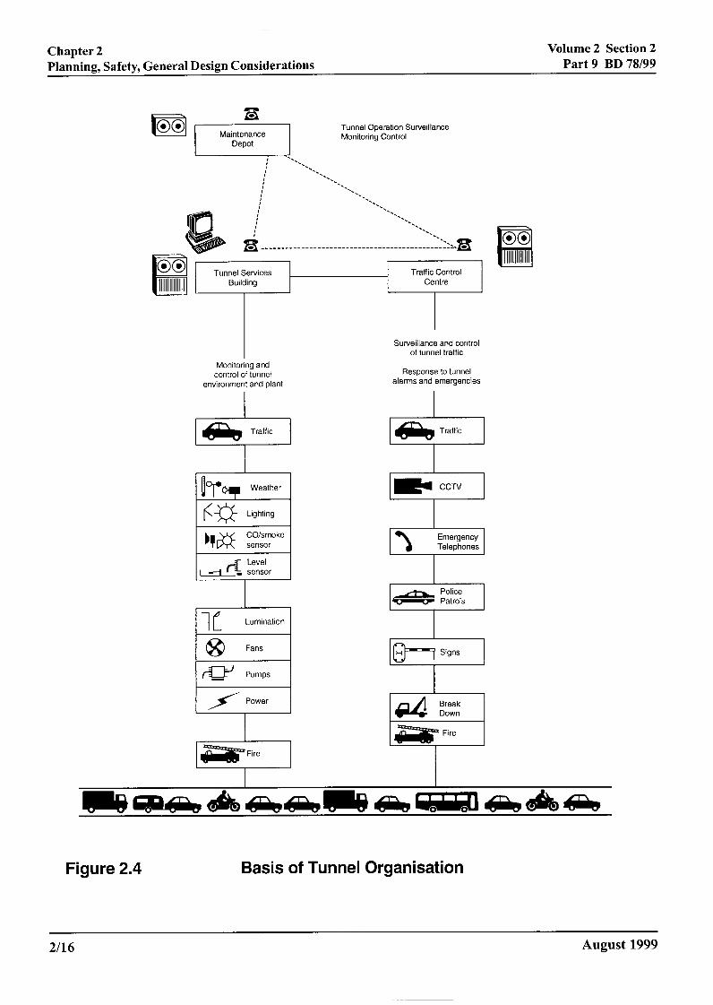
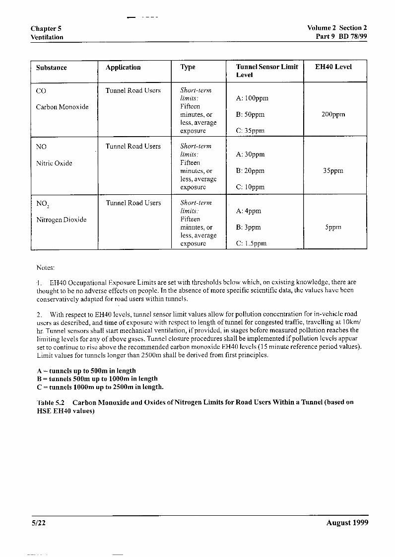
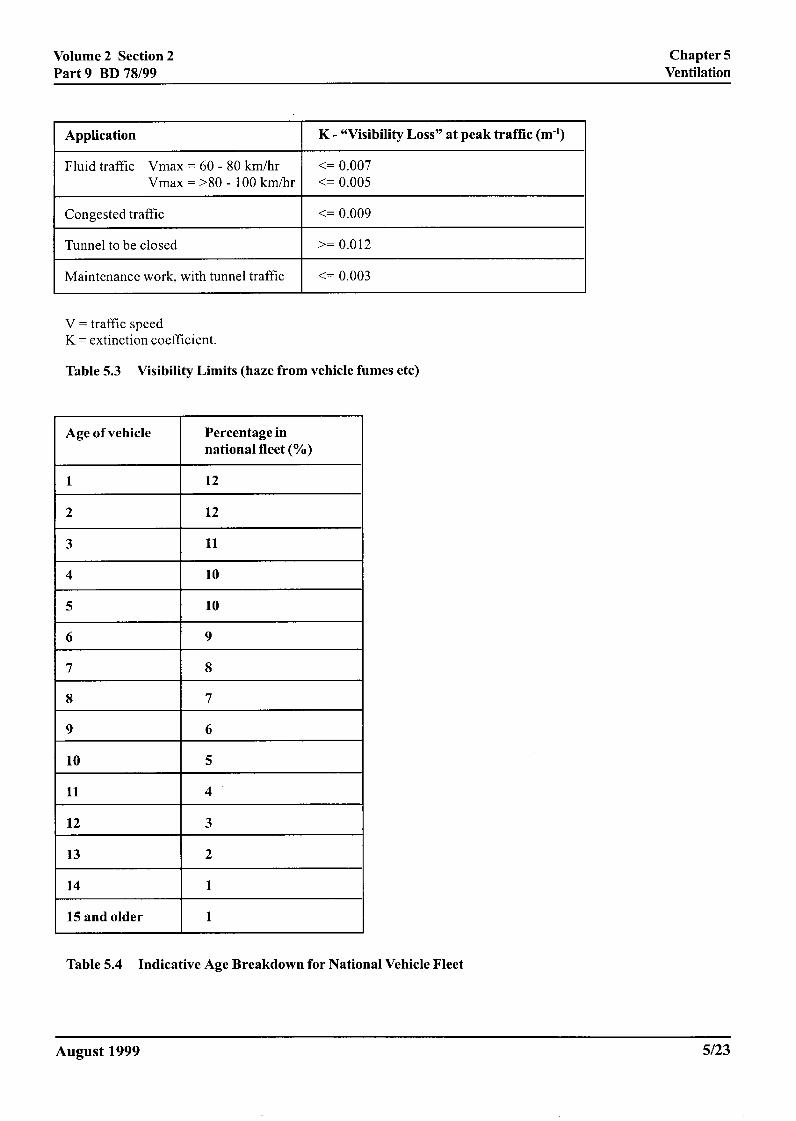
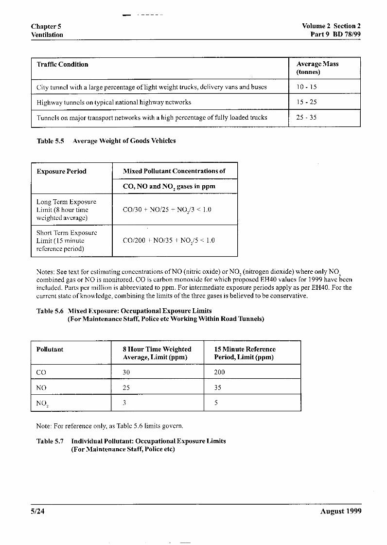
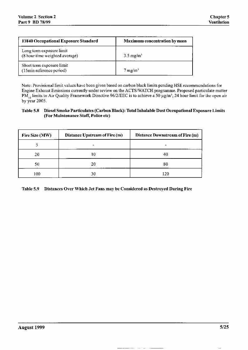
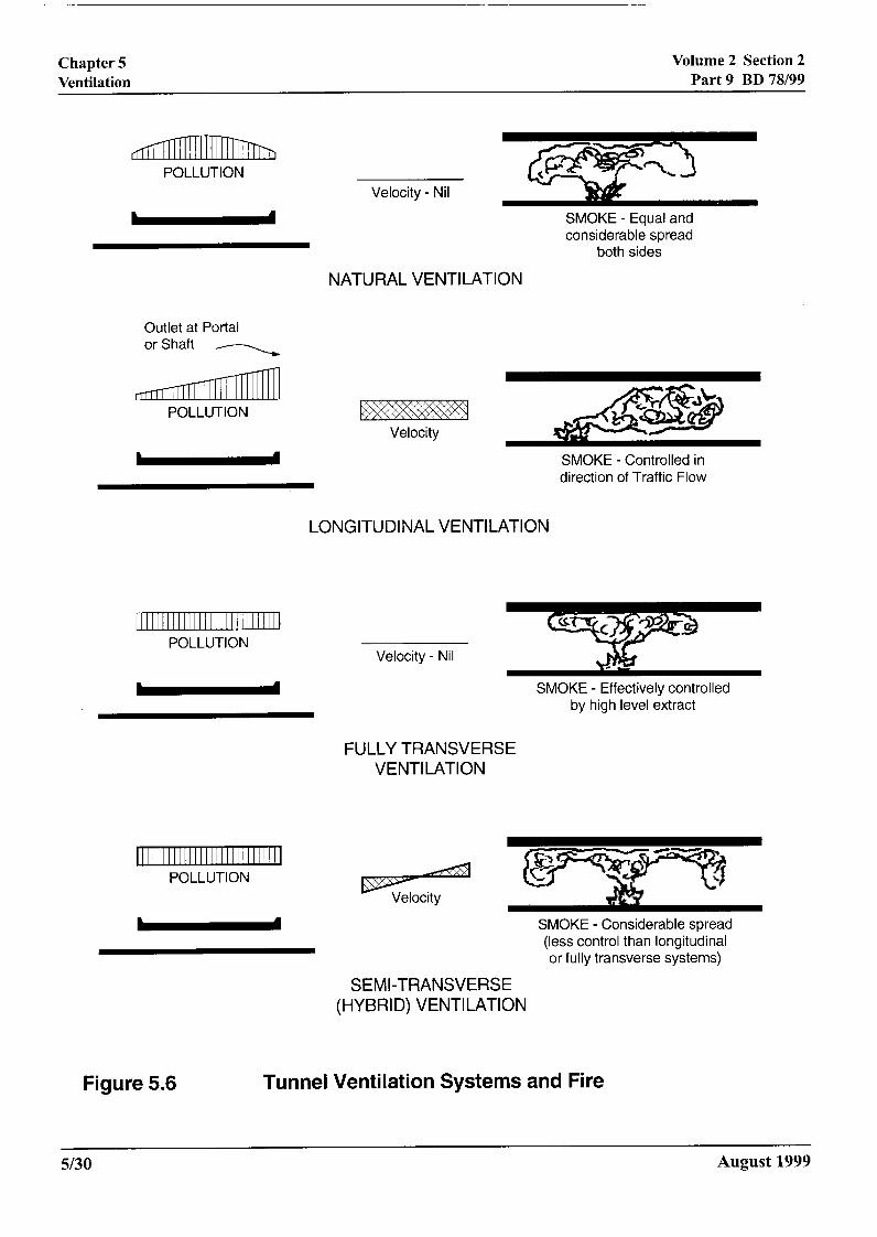
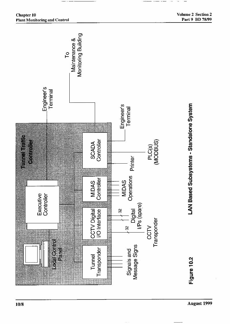
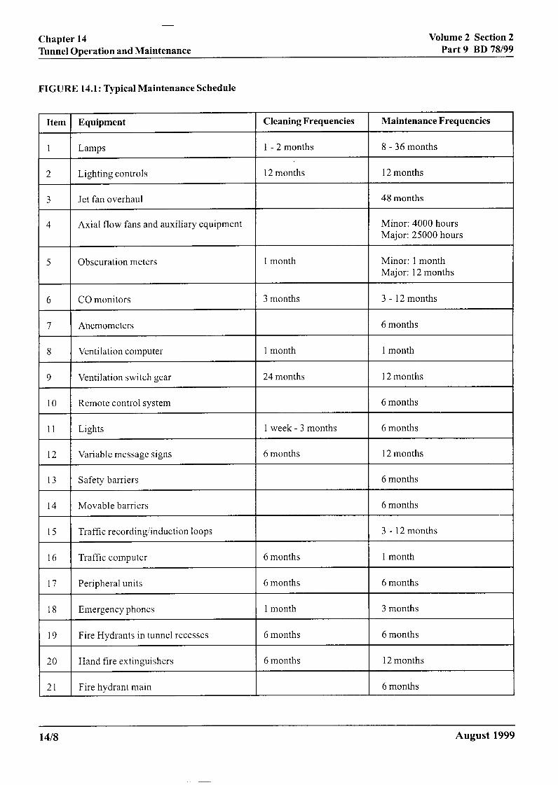
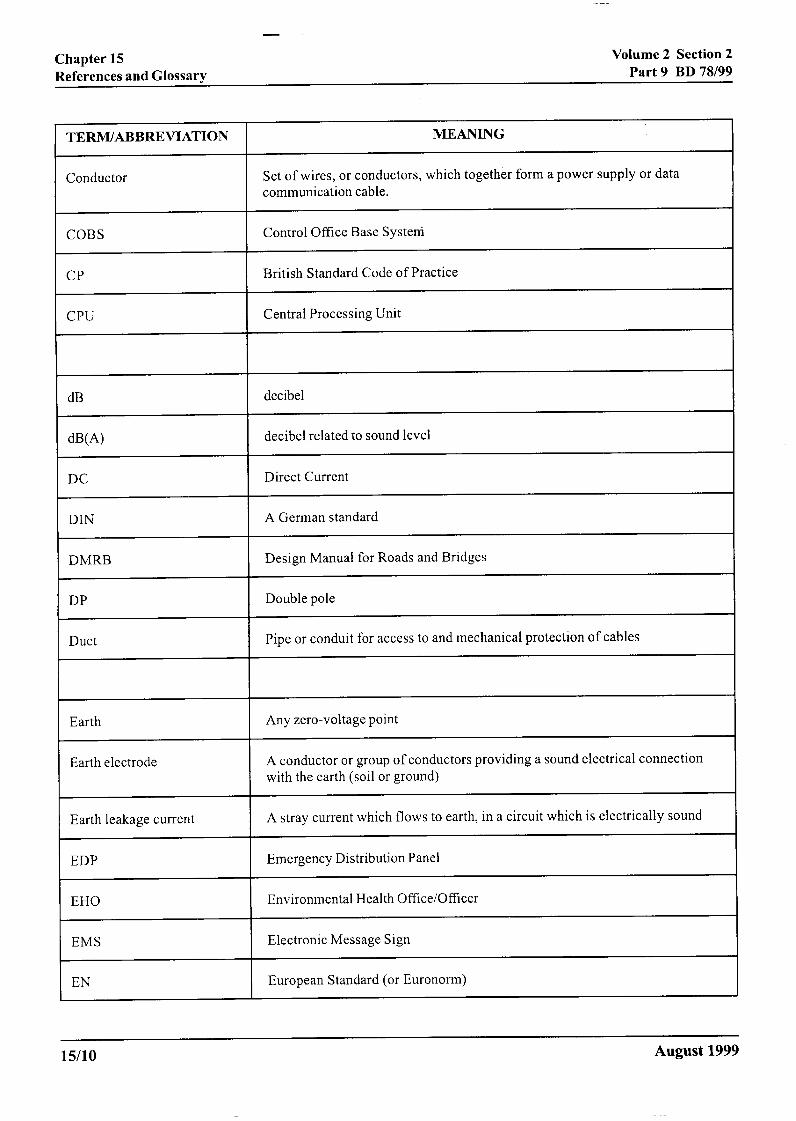
Chapter 8Fire Safety Engineering
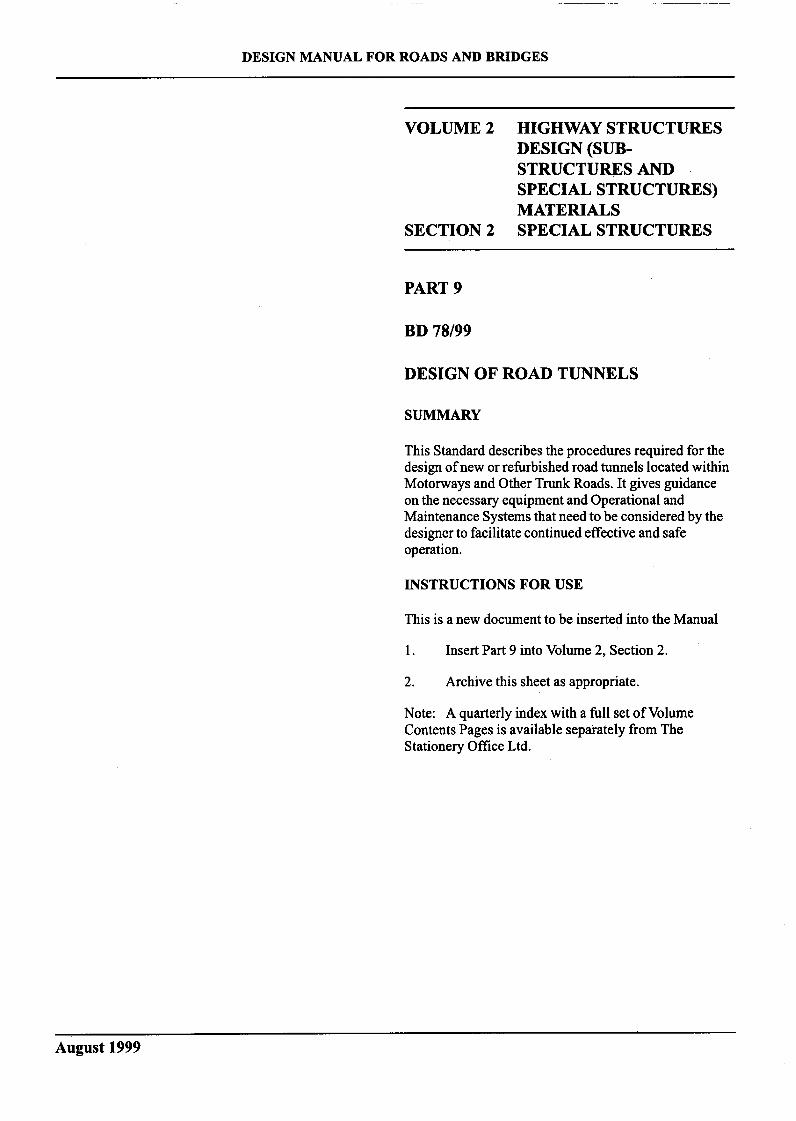
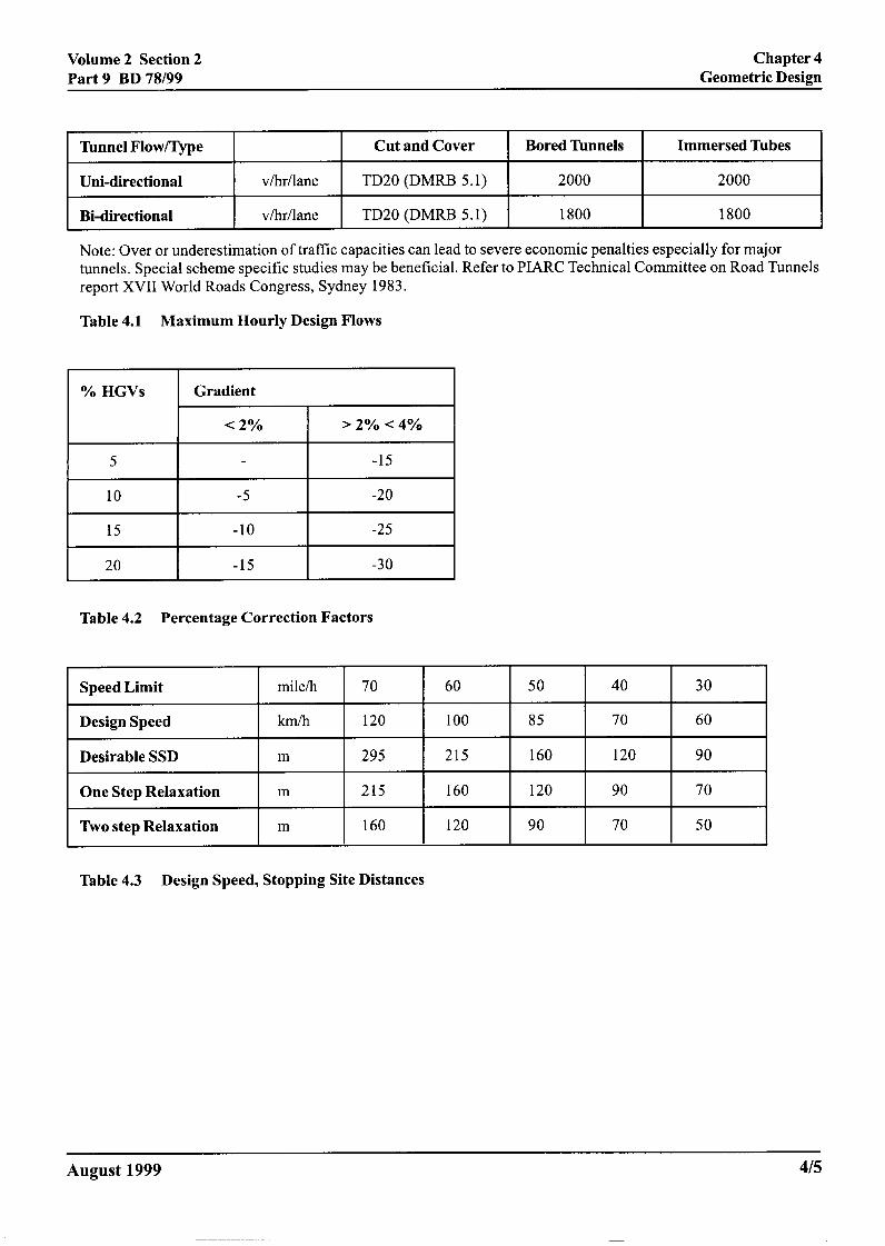
Volume 2 Section 2Part 9 BD 78/99
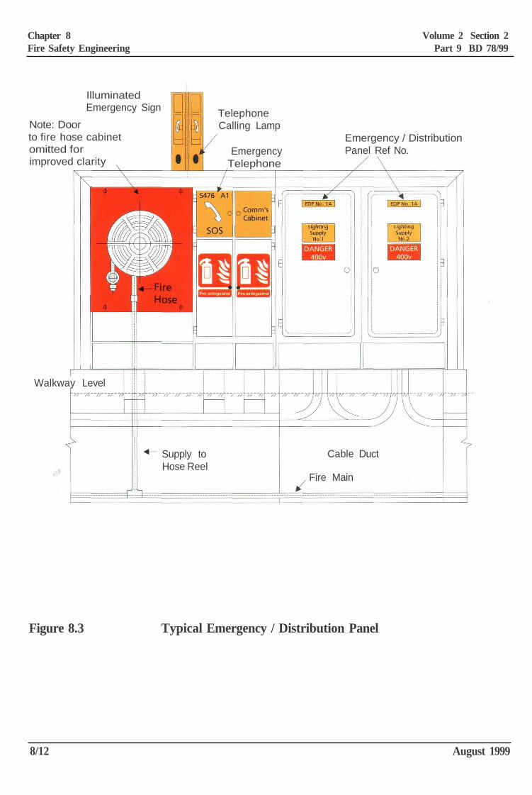
Note: Doorto fire hose cabinetomitted forimproved clarity
IlluminatedEmergency Sign Telephone
Calling Lamp
EmergencyTelephone
Emergency / DistributionPanel Ref No.
Walkway Level
Supply toHose Reel
Cable Duct
Fire Main
Figure 8.3 Typical Emergency / Distribution Panel
8/12 August 1999
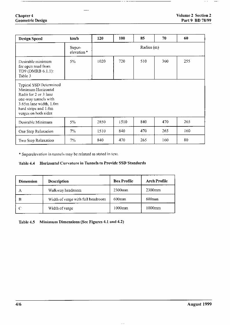
Edge of running lane
Edge marking (white line)
Kerbs
Face of tunnel lining
Door frame
Telephone
Sign
Sign
Telephone
Each leaf opens in onedirection only
Kerbs
Edge marking (white line)
Edge of running lane
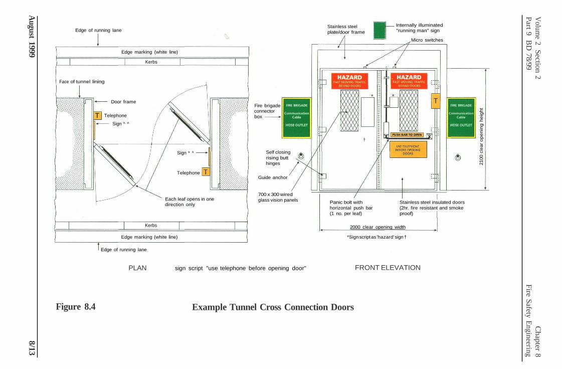
Fire brigadeconnectorbox
Self closingrising butthinges
Guide anchor
700 x 300 wiredglass vision panels
Stainless steelplate/door frame
I Internally illuminated"running man" sign
Micro switches
Panic bolt withhorizontal push bar(1 no. per leaf)
Stainless steel insulated doors(2hr. fire resistant and smokeproof)
2000 clear opening width
*Sign script as 'hazard' sign †
sign script "use telephone before opening door"PLAN
Figure 8.4 Example Tunnel Cross Connection Doors
FRONT ELEVATION
August 1999 8/13
2100
cle
ar o
peni
ng h
eigh
t
Volume 2 Section 2
Chapter 8
Part 9 BD
78/99 Fire Safety Engineering
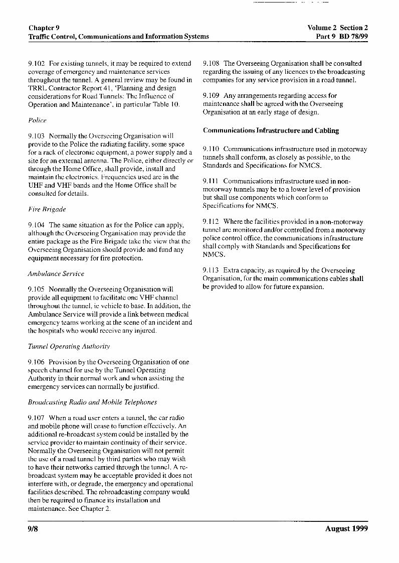
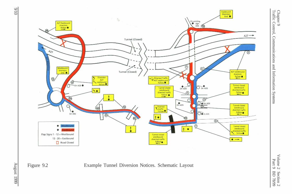
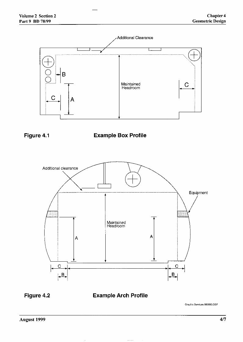
Figure 9.2 Example Tunnel Diversion Notices. Schematic Layout
Chapter 9 Volum
e 2 Section 2Traffic Control, Com
munications and Inform
ation Systems
Part 9 BD 78/99
9/10 A
ugust 1999


![Ventilation During Road Tunnel Emergencies[1]](https://img.pdfslide.net/doc/110x75/553c7d4d4a7959d8258b498b/ventilation-during-road-tunnel-emergencies1.jpg)