Embed Size (px)
Citation preview
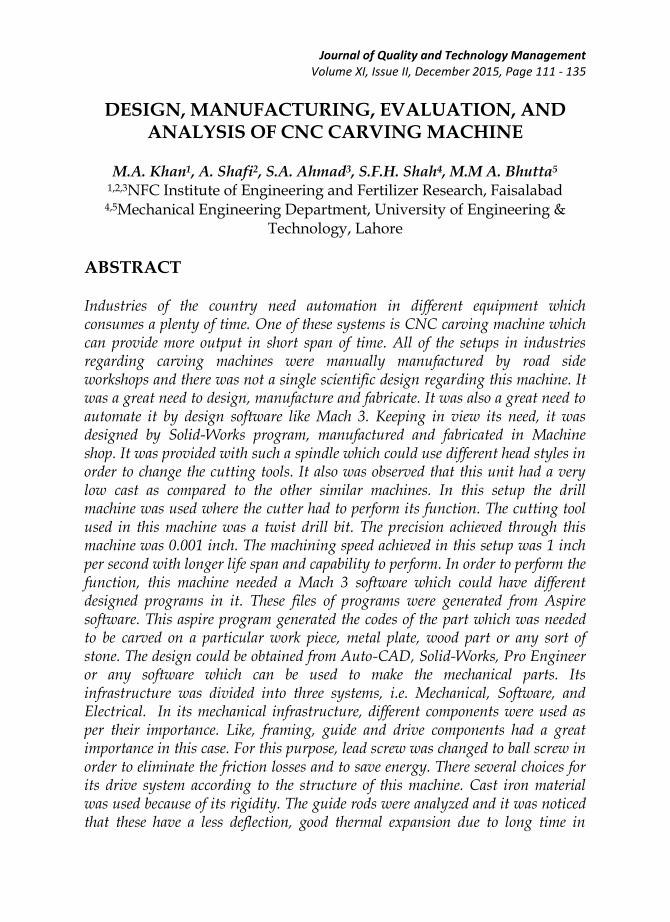
Journal of Quality and Technology Management Volume XI, Issue II, December 2015, Page 111 - 135
DESIGN, MANUFACTURING, EVALUATION, AND ANALYSIS OF CNC CARVING MACHINE
M.A. Khan1, A. Shafi2, S.A. Ahmad3, S.F.H. Shah4, M.M A. Bhutta5
1,2,3NFC Institute of Engineering and Fertilizer Research, Faisalabad 4,5Mechanical Engineering Department, University of Engineering &
Technology, Lahore
ABSTRACT Industries of the country need automation in different equipment which consumes a plenty of time. One of these systems is CNC carving machine which can provide more output in short span of time. All of the setups in industries regarding carving machines were manually manufactured by road side workshops and there was not a single scientific design regarding this machine. It was a great need to design, manufacture and fabricate. It was also a great need to automate it by design software like Mach 3. Keeping in view its need, it was designed by Solid-Works program, manufactured and fabricated in Machine shop. It was provided with such a spindle which could use different head styles in order to change the cutting tools. It also was observed that this unit had a very low cast as compared to the other similar machines. In this setup the drill machine was used where the cutter had to perform its function. The cutting tool used in this machine was a twist drill bit. The precision achieved through this machine was 0.001 inch. The machining speed achieved in this setup was 1 inch per second with longer life span and capability to perform. In order to perform the function, this machine needed a Mach 3 software which could have different designed programs in it. These files of programs were generated from Aspire software. This aspire program generated the codes of the part which was needed to be carved on a particular work piece, metal plate, wood part or any sort of stone. The design could be obtained from Auto-CAD, Solid-Works, Pro Engineer or any software which can be used to make the mechanical parts. Its infrastructure was divided into three systems, i.e. Mechanical, Software, and Electrical. In its mechanical infrastructure, different components were used as per their importance. Like, framing, guide and drive components had a great importance in this case. For this purpose, lead screw was changed to ball screw in order to eliminate the friction losses and to save energy. There several choices for its drive system according to the structure of this machine. Cast iron material was used because of its rigidity. The guide rods were analyzed and it was noticed that these have a less deflection, good thermal expansion due to long time in
Design, Manufacturing, Evaluation, and Analysis of CNC Carving Machine
112|
working condition and strong enough to bear the vibrations. Electrical System needed its controller, computer and its inner electric parts. This machine was totally based on the computer having Mach 3 in order to get the information for the required output. The communication system of all the parts with computer was strong for good performance on the work piece. Keywords: Design, Evaluation, Electrical system, Manufacturing, Mechanical structure, Software system.
1) INTRODUCTION It has been observed that, the manufacturing of the parts for CNC carving machine do not exist. Manufacturers reveal that it is much costly to manufacture it in Pakistan. Another fact for not manufacturing here is that it contains the programming, which is much difficult to update and organize the required programs being used in carving machines. Assembling consists of collecting the manufactured parts, making their synchronization, observing the space requirements for the setup and running the setup according to the required output. It all looks much difficult and costly according to the survey in Pakistan markets. As the programming make the machines, reliable and proficient in their tasks, for major organizations and even for the single buyer. Parts can be worked out and can be observed as the perfect required parts after their machining at CNC cutting, drilling, reaming, milling and Lathe machines. Mostly the CNC machines are made for just single use because these apparatuses are unable to get change in working head parts. Depending upon the fact, that how the design is precise, these machines run with slightly higher speeds to make the surface more finish. Because of very high cost, these machines have become difficult to purchase for the local workshops or markets. In the same way, these can’t reach to the small growing units of the market too. According the survey, it has been observed that there are many conventional machines but all of these setups are conventional, not CNC, and are imported from abroad. This causes the single user to not approach there because of their cost of import.
Journal of Quality and Technology Management
|113
On the base of its important components, CNC machine can be designed and manufactured, like, supporting plates, ball screw, stepper motor, head style and guide rail system. Another design has also been proposed by the James et al., (2010) which is much similar to this design. The project was designed, manufactured and analyzed in order to make its cost little lower than the units being used before. The CNC machine which was designed here in this work, was made for just 650$ whereas, if it is imported from abroad, then it costs as 1600$ minimum. All of the CNC carving machines consisted of three basic systems and these basic systems were again subdivided into their subsystems. The most important system was consisted of Mechanical structure. After that electrical system was made considering the electrical parts. Last but not least, the important for CNC was software control system. Each system needed to be designed precisely for this machine. Railing system was analyzed and synchronized with the other parts which were needed to join with it. The bearing and shaft assembly was chosen according to the standards keeping in view the load of the system on the rails. The movement was made smoother on the rails. The most important factor in order to design the rails was analyzing the deflection due to applied load. Keeping in view the insight, reasonable size and specifications were chosen (Nollet et al., 2008). Ball screw mostly uses the ball bearings in order to get the better movement in threads of nuts and screws. This provides the smooth movement, frictionless support and better rolling contact. Small ball screws are intended to use the large number of ball circuits for proper distribution of load and to improve the efficiency of work being done by CNC carving machine. In order to control the machine limitations, control or limit switches were found as the peripheral devices by which the machine had to work in limits. There were many types of switches but the micro switches were taken out for this purpose. These switches were made to work on the machine in such a way that whenever the end points of the moveable part come closer to the limit switch, it just senses and stops at the specified distance (Tariq Samad, 2001). For the working of CNC carving machine, it was necessary to design the part which was needed. This part could be made on solidworks, Autocad,
Design, Manufacturing, Evaluation, and Analysis of CNC Carving Machine
114|
ProEngineer, or ANSYS. The part file obtained from these software, can be saved as .dxf format. This file was imported in to Aspire 3 which generated the code files for the particular part. In order to run it with proper working conditions, Mach 3 software was used. Before importing the work file into the Mach 3 software, it was necessary to get the designed code file as imported file. The file consisting of codes was generated on Aspire software. Zietasrski (2001) defined the post processing and programming in order to handle the overall operations. Coding and decoding process was also defined by him. Yuwen et al., (2006) worked out for the principles used for the manufacturing of the parts. In order to make the guide curves on the work part, which principles can be used, the information were collected by him. Hwang et al., (1997) also did a great job in this regard. He found the ways to control the operation during manufacturing on machines. Controller was the main focus of this study. By using the new sophisticated components, old larger control units can be replaced with smaller control units. In order to get the more precise cutting and other operations, router was designed as per demand for the work. Efficient routing system is must for the handling of the tool (Broun, Jeremy, 1989). CNC carving machine used the drill bits as the cutting tools, and it had some provisions to change the tool and head style.
2) WORKING PROCESS OF CNC CARVING MACHINE In this machine, it was very easy to work. First of all, it should be kept in mind that it was carving machine by which the different patterns can be drawn on the surface of the objects. For example in order to make coolant paths on the engine surface, this machine could be used just by applying the stronger head style on it. In order to start the work on it, it was necessary to make the patterns (whichever pattern is required). This pattern can be made on solid-works, auto-cad, ansys and pro Engineer software. It could be saved in a format of .dxf. After making the pattern on any software and saving it in dxf format, this file could be imported into another software, which was Aspire 3D software. Here the file was used to generate the codes for the pattern made by solid-works etc. From this software, the file was needed to be saved as txt format. Now, finally this file containing codes regarding the pattern designed was imported into Mach 3 software. Controller installed on the machine used this file
Journal of Quality and Technology Management
|115
instructed the machine to operate according to the codes given in the file of txt format. Work piece can be any plate or object, the drill bit had to move on it to make the same pattern which was made on the software in its initial stages. Guide, framing and mechanical drive systems were three mechanical subsystems in this machine. Ball screws were observed as the efficient screws which were reducing the friction losses. Due to decrease in friction, energy was being saved by this machine too. Actually there were different structures and materials for the frame of the machine and there were also different types of the parts available in the market too. But it was found difficult to synchronize each part with another part. It was better to use the self-manufactured parts as the design was already made on Solid-Works software. Because of rigidity requirements, cast iron material was used for the structure of the machine. In the same way, frame and guide sub-systems were examined on the base of deflection characteristics.
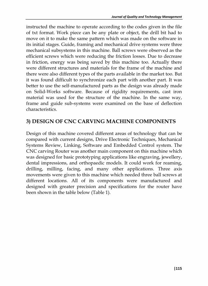
3) DESIGN OF CNC CARVING MACHINE COMPONENTS Design of this machine covered different areas of technology that can be compared with current designs, Drive Electronic Techniques, Mechanical Systems Review, Linking, Software and Embedded Control system. The CNC carving Router was another main component on this machine which was designed for basic prototyping applications like engraving, jewellery, dental impressions, and orthopaedic models. It could work for reaming, drilling, milling, facing, and many other applications. Three axis movements were given to this machine which needed three ball screws at different locations. All of its components were manufactured and designed with greater precision and specifications for the router have been shown in the table below (Table 1).
Design, Manufacturing, Evaluation, and Analysis of CNC Carving Machine
116|
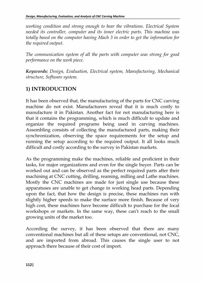
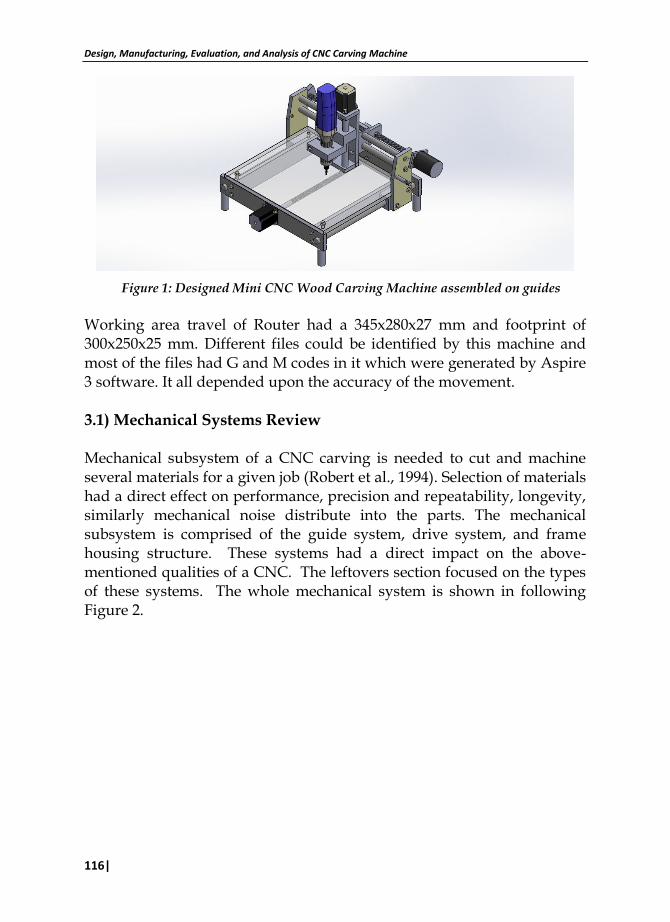
Figure 1: Designed Mini CNC Wood Carving Machine assembled on guides
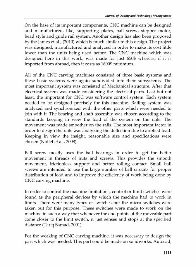
Working area travel of Router had a 345x280x27 mm and footprint of 300x250x25 mm. Different files could be identified by this machine and most of the files had G and M codes in it which were generated by Aspire 3 software. It all depended upon the accuracy of the movement. 3.1) Mechanical Systems Review Mechanical subsystem of a CNC carving is needed to cut and machine several materials for a given job (Robert et al., 1994). Selection of materials had a direct effect on performance, precision and repeatability, longevity, similarly mechanical noise distribute into the parts. The mechanical subsystem is comprised of the guide system, drive system, and frame housing structure. These systems had a direct impact on the above-mentioned qualities of a CNC. The leftovers section focused on the types of these systems. The whole mechanical system is shown in following Figure 2.
Journal of Quality and Technology Management
|117
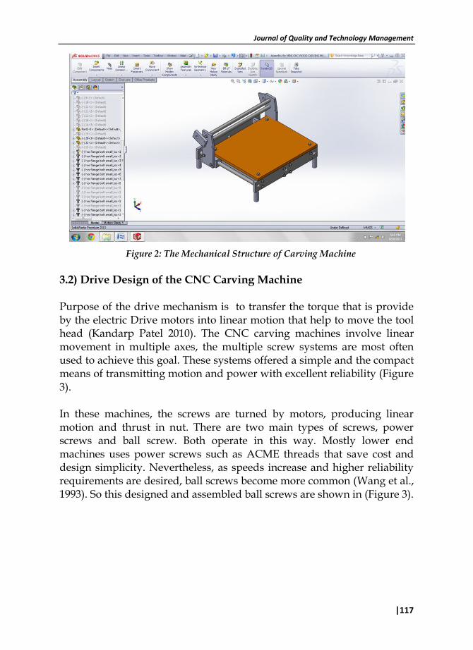
Figure 2: The Mechanical Structure of Carving Machine
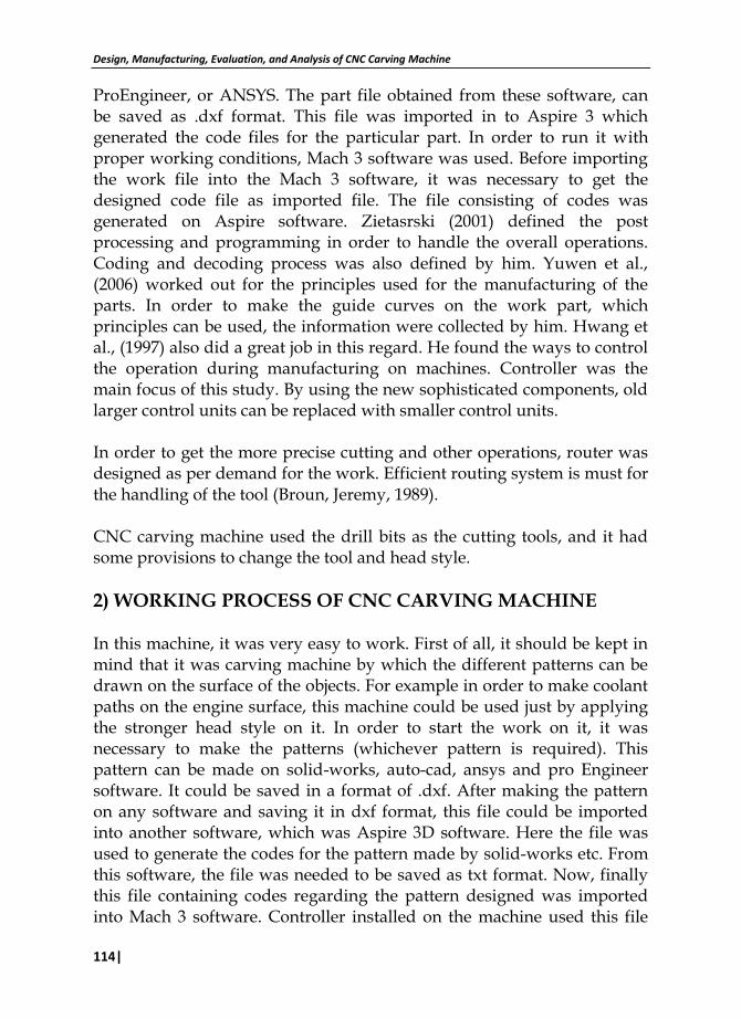
3.2) Drive Design of the CNC Carving Machine Purpose of the drive mechanism is to transfer the torque that is provide by the electric Drive motors into linear motion that help to move the tool head (Kandarp Patel 2010). The CNC carving machines involve linear movement in multiple axes, the multiple screw systems are most often used to achieve this goal. These systems offered a simple and the compact means of transmitting motion and power with excellent reliability (Figure 3). In these machines, the screws are turned by motors, producing linear motion and thrust in nut. There are two main types of screws, power screws and ball screw. Both operate in this way. Mostly lower end machines uses power screws such as ACME threads that save cost and design simplicity. Nevertheless, as speeds increase and higher reliability requirements are desired, ball screws become more common (Wang et al., 1993). So this designed and assembled ball screws are shown in (Figure 3).
Design, Manufacturing, Evaluation, and Analysis of CNC Carving Machine
118|
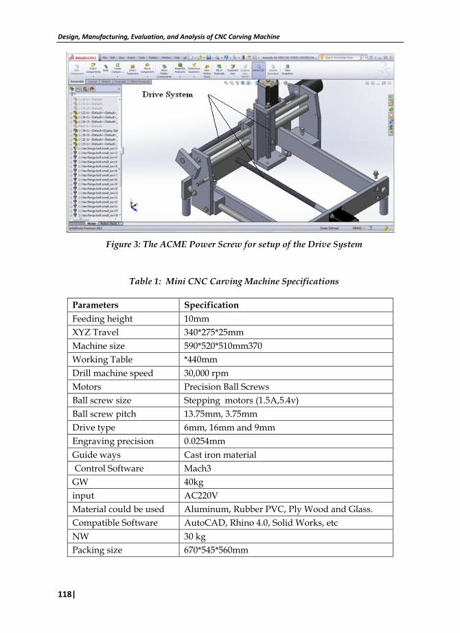
Figure 3: The ACME Power Screw for setup of the Drive System
Table 1: Mini CNC Carving Machine Specifications
Parameters Specification
Feeding height 10mm
XYZ Travel 340*275*25mm
Machine size 590*520*510mm370
Working Table *440mm
Drill machine speed 30,000 rpm
Motors Precision Ball Screws
Ball screw size Stepping motors (1.5A,5.4v)
Ball screw pitch 13.75mm, 3.75mm
Drive type 6mm, 16mm and 9mm
Engraving precision 0.0254mm
Guide ways Cast iron material
Control Software Mach3
GW 40kg
input AC220V
Material could be used Aluminum, Rubber PVC, Ply Wood and Glass.
Compatible Software AutoCAD, Rhino 4.0, Solid Works, etc
NW 30 kg
Packing size 670*545*560mm
Journal of Quality and Technology Management
|119
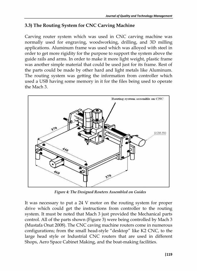
3.3) The Routing System for CNC Carving Machine Carving router system which was used in CNC carving machine was normally used for engraving, woodworking, drilling, and 3D milling applications. Aluminum frame was used which was alloyed with steel in order to get more rigidity for the purpose to support the system above the guide rails and arms. In order to make it more light weight, plastic frame was another simple material that could be used just for its frame. Rest of the parts could be made by other hard and light metals like Aluminum. The routing system was getting the information from controller which used a USB having some memory in it for the files being used to operate the Mach 3.
Figure 4: The Designed Routers Assembled on Guides
It was necessary to put a 24 V motor on the routing system for proper drive which could get the instructions from controller to the routing system. It must be noted that Mach 3 just provided the Mechanical parts control. All of the parts shown (Figure 3) were being controlled by Mach 3 (Mustafa Onat 2008). The CNC caving machine routers come in numerous configurations; from the small head-style “desktop” like K2 CNC, to the large head style or Industrial CNC routers that are used in different Shops, Aero Space Cabinet Making, and the boat-making facilities.
Design, Manufacturing, Evaluation, and Analysis of CNC Carving Machine
120|
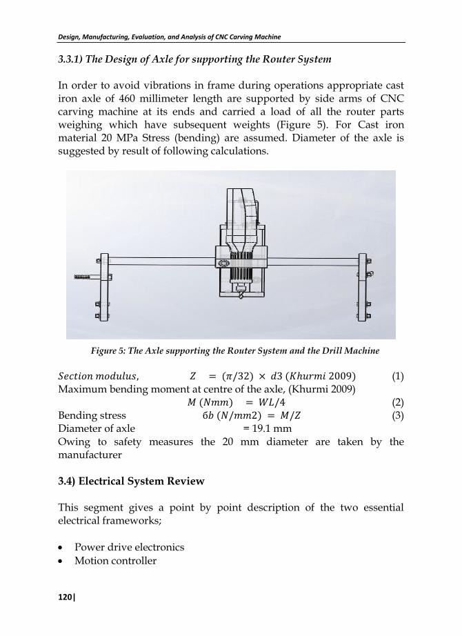
3.3.1) The Design of Axle for supporting the Router System In order to avoid vibrations in frame during operations appropriate cast iron axle of 460 millimeter length are supported by side arms of CNC carving machine at its ends and carried a load of all the router parts weighing which have subsequent weights (Figure 5). For Cast iron material 20 MPa Stress (bending) are assumed. Diameter of the axle is suggested by result of following calculations.
Figure 5: The Axle supporting the Router System and the Drill Machine
(1) Maximum bending moment at centre of the axle, (Khurmi 2009) (2) Bending stress (3) Diameter of axle = 19.1 mm Owing to safety measures the 20 mm diameter are taken by the manufacturer 3.4) Electrical System Review This segment gives a point by point description of the two essential electrical frameworks;
Power drive electronics
Motion controller
Journal of Quality and Technology Management
|121
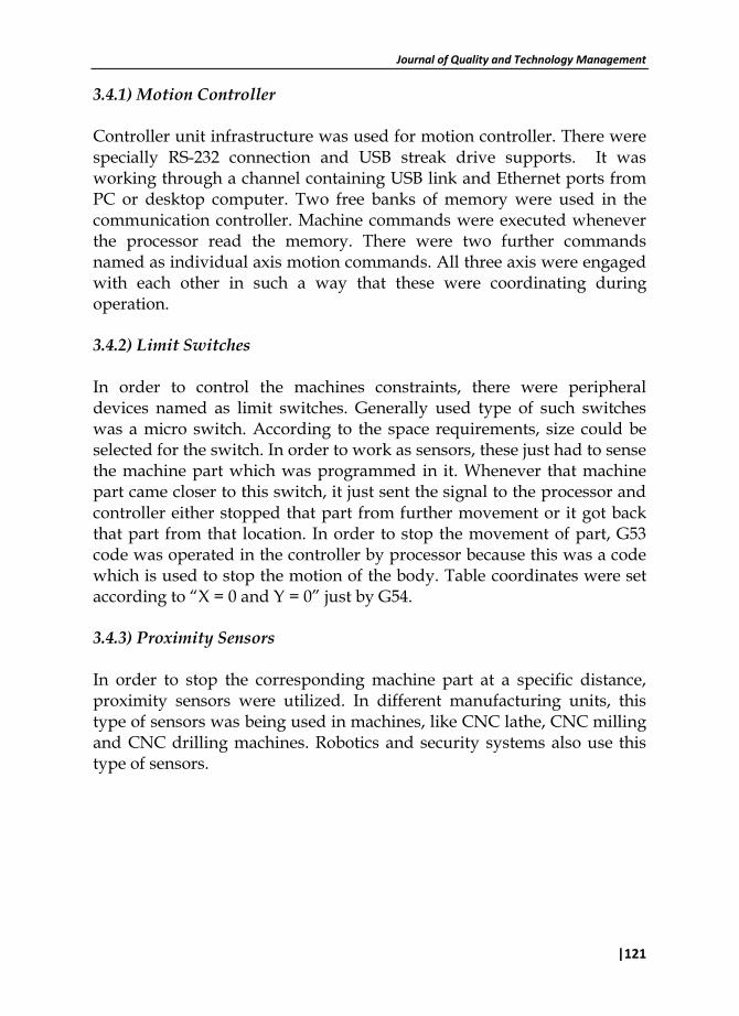
3.4.1) Motion Controller Controller unit infrastructure was used for motion controller. There were specially RS-232 connection and USB streak drive supports. It was working through a channel containing USB link and Ethernet ports from PC or desktop computer. Two free banks of memory were used in the communication controller. Machine commands were executed whenever the processor read the memory. There were two further commands named as individual axis motion commands. All three axis were engaged with each other in such a way that these were coordinating during operation. 3.4.2) Limit Switches In order to control the machines constraints, there were peripheral devices named as limit switches. Generally used type of such switches was a micro switch. According to the space requirements, size could be selected for the switch. In order to work as sensors, these just had to sense the machine part which was programmed in it. Whenever that machine part came closer to this switch, it just sent the signal to the processor and controller either stopped that part from further movement or it got back that part from that location. In order to stop the movement of part, G53 code was operated in the controller by processor because this was a code which is used to stop the motion of the body. Table coordinates were set according to “X = 0 and Y = 0” just by G54. 3.4.3) Proximity Sensors In order to stop the corresponding machine part at a specific distance, proximity sensors were utilized. In different manufacturing units, this type of sensors was being used in machines, like CNC lathe, CNC milling and CNC drilling machines. Robotics and security systems also use this type of sensors.
Design, Manufacturing, Evaluation, and Analysis of CNC Carving Machine
122|
Figure 6: Limit Switch on Machine
There was another type of sensing elements, like Capacitive switches, which were sensing the objects just by detecting the capacitance around them. Another sensor which was called as radio frequency senor, was also studied to apply it on the machine but it was totally differing from the object. It was working in such a way that whenever the part came closer to the sensor, it just sent the signal to stop or run the part. These switches were not used because these were more sensitive than others to detect the metal parts (Frank et al., 1988). Another type of sensors which was more reliable than radio frequency sensors was inductive proximity switches. These were checked in such a way that whenever the object came closer to these sensors, these just generated magnetic field. It was a better option but the main drawback in these switches was that these were detecting just metal parts, not other materials. That’s why these were not used in this project. 3.4.4) Features of Proximity Sensors in CNC Carving Machine Spectacular popularity of these sensors in manufacturing units, industries and different workshops is growing on and on because of their excellent features. During operation, these sensors have to perform the following duties.
Journal of Quality and Technology Management
|123
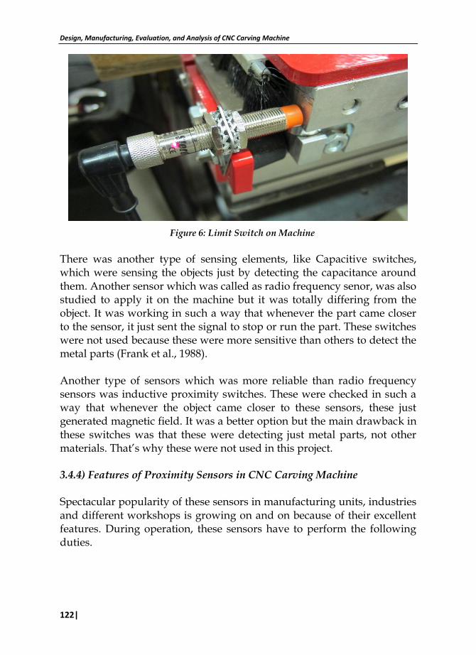
Table 2: Properties and Features of Proximity Sensors
Output Type NPN
Mounting CNC Carving Machine
Proximity Sensor Sensing Distance 5mm
Proximity Sensor Sensing Distance Range 2 to 7mm
Operating Temperature Classification Industrial
Operating Temp Range -40C to 85C
Operating Supply Voltage (Max) 40V
Operating Supply Voltage (Min) 10V
Operating Supply Voltage (Type) 12/15/18/24V
These sensors had high switching frequency and high approach speeds. These are resistant to large vibrations These are resistant to coolants and cutting oils 3.4.5) Stepper Motor Drives The driver just had to provide the rated amount of current in shorter span of time to the motor. The voltages coming from the driver were very important to be controlled for the better performance of the motor. There were inductive and some other resistance in the motor for a specific time interval. The rated amount of the current was supplied to the motor and it was performing according to the signals provided by the controller. It was noticed that at higher speeds it was reducing the torque on the motor shaft. This reduction in torque was making the motor to run at higher speeds and this was controlled by applying the loads in its operation. Whenever the load was applied its speed was decreased. There were two main types of drives by which the stepper motor had to run. Constant voltage drive and Constant current drive. 3.4.6) Display to show the Work Operation and Program It was necessary to see the codes being used for the specific time interval. For this purpose, LCD display was used which provided all the details which were generated by Aspire 3 software. Here the observer could see the information easily. Different parameters were observed on the display i.e. speed, feed, zero coordinates, home positions and park positions. All
Design, Manufacturing, Evaluation, and Analysis of CNC Carving Machine
124|
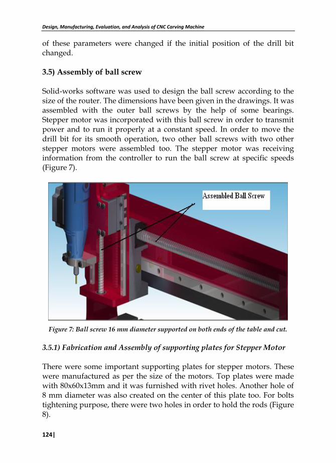
of these parameters were changed if the initial position of the drill bit changed. 3.5) Assembly of ball screw Solid-works software was used to design the ball screw according to the size of the router. The dimensions have been given in the drawings. It was assembled with the outer ball screws by the help of some bearings. Stepper motor was incorporated with this ball screw in order to transmit power and to run it properly at a constant speed. In order to move the drill bit for its smooth operation, two other ball screws with two other stepper motors were assembled too. The stepper motor was receiving information from the controller to run the ball screw at specific speeds (Figure 7).
Figure 7: Ball screw 16 mm diameter supported on both ends of the table and cut.
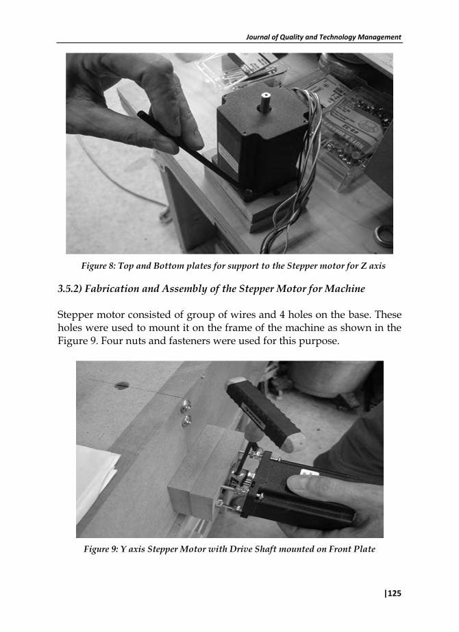
3.5.1) Fabrication and Assembly of supporting plates for Stepper Motor There were some important supporting plates for stepper motors. These were manufactured as per the size of the motors. Top plates were made with 80x60x13mm and it was furnished with rivet holes. Another hole of 8 mm diameter was also created on the center of this plate too. For bolts tightening purpose, there were two holes in order to hold the rods (Figure 8).
Journal of Quality and Technology Management
|125
Figure 8: Top and Bottom plates for support to the Stepper motor for Z axis
3.5.2) Fabrication and Assembly of the Stepper Motor for Machine Stepper motor consisted of group of wires and 4 holes on the base. These holes were used to mount it on the frame of the machine as shown in the Figure 9. Four nuts and fasteners were used for this purpose.
Figure 9: Y axis Stepper Motor with Drive Shaft mounted on Front Plate
Design, Manufacturing, Evaluation, and Analysis of CNC Carving Machine
126|
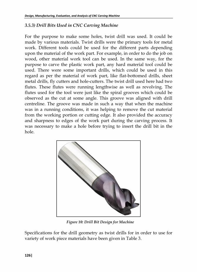
3.5.3) Drill Bits Used in CNC Carving Machine For the purpose to make some holes, twist drill was used. It could be made by various materials. Twist drills were the primary tools for metal work. Different tools could be used for the different parts depending upon the material of the work part. For example, in order to do the job on wood, other material work tool can be used. In the same way, for the purpose to carve the plastic work part, any hard material tool could be used. There were some important drills, which could be used in this regard as per the material of work part, like flat-bottomed drills, sheet metal drills, fly cutters and hole-cutters. The twist drill used here had two flutes. These flutes were running lengthwise as well as revolving. The flutes used for the tool were just like the spiral grooves which could be observed as the cut at some angle. This groove was aligned with drill centreline. The groove was made in such a way that when the machine was in a running conditions, it was helping to remove the cut material from the working portion or cutting edge. It also provided the accuracy and sharpness to edges of the work part during the carving process. It was necessary to make a hole before trying to insert the drill bit in the hole.
Figure 10: Drill Bit Design for Machine
Specifications for the drill geometry as twist drills for in order to use for variety of work piece materials have been given in Table 3.
Journal of Quality and Technology Management
|127
Table 3: Standard Geometry for High-Speed Steel Twist Drills
Point Lip Relief Chisel Edge Helix
Material Angle, deg Angle, deg Angle, deg Angle, deg Point grind
Steels 118 10–15 125–135 24–32 Standard
Cast irons 118 8–12 125–135 24–32 Standard
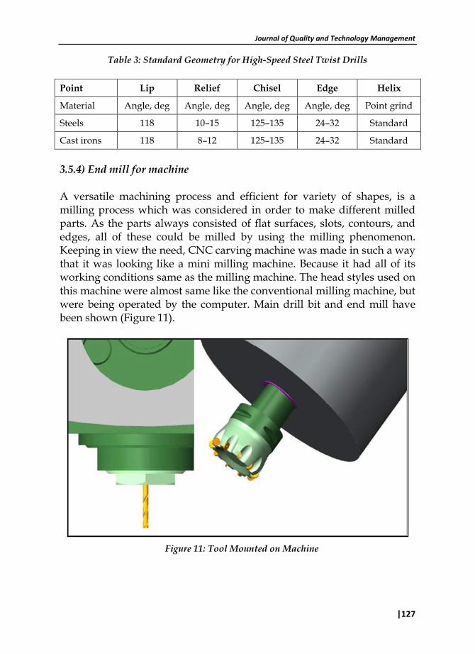
3.5.4) End mill for machine A versatile machining process and efficient for variety of shapes, is a milling process which was considered in order to make different milled parts. As the parts always consisted of flat surfaces, slots, contours, and edges, all of these could be milled by using the milling phenomenon. Keeping in view the need, CNC carving machine was made in such a way that it was looking like a mini milling machine. Because it had all of its working conditions same as the milling machine. The head styles used on this machine were almost same like the conventional milling machine, but were being operated by the computer. Main drill bit and end mill have been shown (Figure 11).
Figure 11: Tool Mounted on Machine
Design, Manufacturing, Evaluation, and Analysis of CNC Carving Machine
128|
3.5.5) Materials information The tools should not bend and break depends on the rigidity. Tool should not be flexible in any way. According to the rigidity theory, the materials used to form different objects always get the standards shapes, like rectangular, circular, cubic, cylindrical etc. Rods are rigid structure from all of the above shapes, so the tools had to use the shape like rods. The material used for the cutting tool was observed to be stronger than the material being used for the work part. Two kinds of rigidity were considered in this regard: Macroscopic rigidity was helping in a way that the material will never flex or bend during the operation. Infinitesimal rigidity meant that the tool had not to flex by even amount of loads. There were two essentially different kinds of rigidity. The materials used for the cutting tool has been presented below. 3.5.6) Cast Iron In order to make the tool of cast iron, the metal was heated and then liquefied. After the liquefaction, it was poured down to mold in order to solidify it as per the required shape. Pig iron was used as the main metal. In some cases, the alloys could also be used. The reason, for not using the cast iron material for this tool, was that carbide impurities were involved in this material. 3.5.7) Aluminum Another important material was aluminum, and in markets, it was silvery white and ductile metal with light weight. It had lower density and more rigidity than iron. Due to passiveness, it always resisted corrosion. Most of the parts and elements were made of aluminum and its alloys.
Journal of Quality and Technology Management
|129
3.6) Automation of CNC Carving Machine For the purpose of higher productivity, quality, quantity of output parts, automation was applied to this machine. Quick and accurate manufacturing was achieved by such automation. Tool work, tool cutting and feeding into the work part etc. was achieved more reliable on this machine by using the computer numerical control. The system used in this machine was incorporated with mechanical, electrical and electromechanical as per requirements. As per degree of automation, the different machine tools could be used. It was confirmed that all auxiliary and handling operations were done automatically by computer. Only the practice was needed to control and to operate the Mach 3.
Strong graphic card was needed for the very high GUI to run this software
In this software, different types of files could be imported to generate the G-Code
Automation system needed two different programs to change the other file formats
Numerous cutting techniques could be achieved by this automation
In order to make the part quick, already designed templates could be used sometimes.
For automation, Mach 3 was essential tool to operate the machine.
3.6.1) Features of Mini CNC Wood Carving Machine:
Multiple relay control
Routing speed in 3 Axis as well as Spindle speed control
Full screen eligibility
Manual pulse generation
3.6.2) Computer requirements for Mini CNC Wood Carving Machine:
256 MB Ram
Windows 2000/XP
Desktop PC (no laptop)
1 GHZ Processor
Non-integrated Video Card
Design, Manufacturing, Evaluation, and Analysis of CNC Carving Machine
130|
3.6.3) Characteristics of CNC Carving Machine
less expensive
User friendly
High resolution requires higher computer requirements
Precise mapping to see finished product before cutting 3.7) Design Software for making Work Part In order to make the work part, different software could be used. But it should be kept in mind that the part being designed on any tool should be within limits of the bed on which the tool had to work. Mainly, Auto-CAD, software was used to design the shapes for carving. Other software like Solid-Works, Pro Engineer and Catia could also be used for this purpose. It all depends upon the availability of the software. Whichever the software we had, it just had to design the work part according to the dimensions. As per the focus of industries and local markets, Solid-Works software was used to design the parts 3.7.1) Files to Decode: Whenever the parts were made on any software, these could be saved in the following formats. BMP, RLE, TIF, EMF, WMF, PCX, ICO, CUR, PNG, TARAGA, PPM. After the accomplishment of save option, the files of the part were imported to Aspire software which was used to decode the file from these formats to G Code. 3.7.2) Mach 3 Software for CNC Carving Machine This software has gained popularity in automation of the machines. Different machines including lathe, milling, drilling and cutting, all are using this software if these are CNC machines. A complete setup of desktop computer along with the carving controller was needed for CNC Carving machine. It was made as 3 Axis machine and the controller used for it has to control its all 3 axis movements. It was needed to import DXF,
Journal of Quality and Technology Management
|131
JPG, BMP, and HPGL file type. This file had all codes needed for the required part. CNC just had to detect the codes and to run as per instructions of the controller. This Mach 3 had a vast ability to get the files from some other external software. Lazy Cam tool had to use different files types in order to import them in the controller of the CNC Carving machine. VB and Wizards were the mini programs which could write down the G-Code easily. Slots, holes, text engraving and digitalizing could be done by this tool. 3.8) Importance of CNC Carving Machine for Pakistani Industries The industries and local workshops have recognized that this is an important tool to save time and to get the more output with quality work. Small risk of accidents, material saving, better efficiency and energy savings were the main factors because of which it got the popularity. Because of its importance, larger industries are interested to utilize this concept for lining of engines in order to make the paths for coolants on various metal blocks etc. It also provided increased production within shorter span of time and it was the biggest advantage of the machine. If the large products are being produced on daily or weekly basis, then this tool is the best to go ahead for making the carving patterns, putting different shapes on the surfaces of the objects, putting some lines, (straight, angles, curved etc.). For making the production reliable and efficient, wood router gives the better results with no waste of material. CNC routers are always controlled by computer and products are made by the routers easily if it is computer numerically controlled. If there is larger amount of waste material during the operation on work parts carving, CNC carving machine should be used to avoid the wastage of important material. The quality and material saving enables industries to save their thousands of dollars daily. Otherwise all of this money was going to be wasted due to wastage of material and time.
Design, Manufacturing, Evaluation, and Analysis of CNC Carving Machine
132|
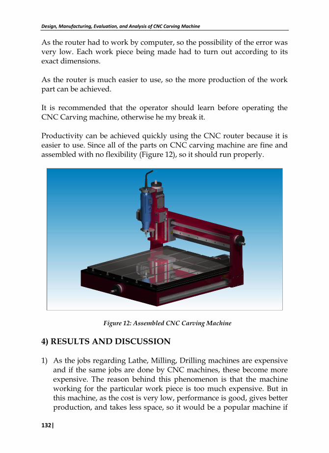
As the router had to work by computer, so the possibility of the error was very low. Each work piece being made had to turn out according to its exact dimensions. As the router is much easier to use, so the more production of the work part can be achieved. It is recommended that the operator should learn before operating the CNC Carving machine, otherwise he my break it. Productivity can be achieved quickly using the CNC router because it is easier to use. Since all of the parts on CNC carving machine are fine and assembled with no flexibility (Figure 12), so it should run properly.
Figure 12: Assembled CNC Carving Machine
4) RESULTS AND DISCUSSION 1) As the jobs regarding Lathe, Milling, Drilling machines are expensive
and if the same jobs are done by CNC machines, these become more expensive. The reason behind this phenomenon is that the machine working for the particular work piece is too much expensive. But in this machine, as the cost is very low, performance is good, gives better production, and takes less space, so it would be a popular machine if
Journal of Quality and Technology Management
|133
road side vendors, workshops, and industries in all over Pakistan will use it to draw pattern on the engines, metal boards, wood works.
2) The price of this machine at the time of its manufacturing and fabrication was just 65000/- Rs. As this is a very low price as compared to other Machines, so poor fabricators can also purchase this machine to increase their production.
3) As this machine was more efficient and precise, so time to produce a part was drastically decreased. Labor required for this setup was very less in numbers. Material wastage was not there in this machine.
4) In order to slide the structure or the rods, there were two options, i.e. use of ball screw and lead screw. The ball screw was used to give the movement in order to decrease to the friction between the sliding parts.
5) Ball screw caused to decrease the energy. 6) It was noticed that as the work required from this machine was to
draw different pattern on work parts. Any material softer than cast iron could be used through this machine i.e. rubber, plastic, wood, aluminum foil and different iron plates could be used.
7) It was noticed that ball type sideways changed the efficiency of the machine. It was very strong to bear the loads in varying operations.
8) As the Mach 3 has a vast acceptance of different formats of the files, so it was used to execute the coding/ programming for the particular operation.
9) In order to get the pulses stepper motor was used in order to move the parts according to the machined parts. Its precision could be increased just by replacing the stepper motor to servo motor. But as the servo motor is little expensive, stepper motor was used and it was working efficiently.
10) The limit switches attached against the movable parts were very efficient and were preventing the moving parts to be extravagant from their limits. The switches were made by using proximity sensor.
11) This machine was built for just three axis. 12) Slide ways were made up of cast iron and were bearing the loads and
vibration produced due to the functionality of the machine. 13) Whole machine was assembled in a way that all of its weight was
being divided into four equal parts in a case when the router was in the center of the machine.
14) In order to lower the voltage, stepdown transformers were used with different capacities as the instruments being used in the machine were built with lower voltages.
Design, Manufacturing, Evaluation, and Analysis of CNC Carving Machine
134|
15) In this machine different types of the wire were used for example, in order to control the stepper motor white wire was used, in order to turn ON or OFF the machine, red and black wires were used whereas brown and black wires were just output wires.
16) In order to achieve the 12 volts for stepper motor, 2 regulators were used and in case of higher capacity motor, regulators would be increased.
17) This motor was rotating the twist drill bit up to 30, 000 RPM, so the neatness and precision was being achieved from it. In order to get more precision and neatness, this speed could be increased.
5) REFERENCES
Anonymous, (2012). Punjab Development Statistics. Bureau of Statistics Government of the Punjab Lahore, Pakistan.
F. C Wang and D. C. H. Yang (1993). Interpolation for precision machining. Computer Aided Design, 25(5):281-288.
F. Nollet, T. Floquet, and W. Perruquetti (2008). Observer-based second order sliding mode control laws for stepper motors. Control Engineering Practice, 16(4):429-443.
Frank and A. Schmid (1988). Non-circular contours on CNC cylindrical grinding machines. Robotics and Computer Integrated Manufacturing, 4(1-2):211{218.
Gene F. Franklin, J. David Powell, and Abbas Emami-Naeini (2010) Feedback control of dynamic systems Pearson, Upper Saddle River, NJ.
James Williams, Shawn Gossett, Eric Blankenship, Eddie Spiller, Pat Brokaw, Brian Hagene, (2010) Saluki Engineering Company Senior Engineering Design Center College of Engineering Mailcode 6603 Carbondale IL 62901-6603 618-889-7644
Jeremy B. (1989). The Incredible Router. Lewes, East Sussex: Guild of Master Craftsman Publications. ISBN 0-946819-17-3.
Kaan Erkorkmaz, Chi-Ho Yeung, and Yusuf Altintas (2006) .Virtual CNC system. Part II. High speed contouring application International Journal of Machine Tools Manufacture, 46(10):1124-1138
Kandarp Patel (2010). Web based automatic tool path planning strategy for complex sculptured surfaces. University of Waterloo, Waterloo, Ont.
Journal of Quality and Technology Management
|135
L. Hwang, M. H. Wei, and W. J. Jieng. (1997). Non-circular cutting with a lathe usinga three-stage intelligent controller. Robotics and Computer-Integrated Manufacturing, 13(3):181-191.
Mustafa Onat (2008). Developing a PC- and SMS-mC-based stepper motor drive set. International Journal of Engineering Education, 24(1):23-21.
Robert H. Todd, Dell K. Allen, Leo Alting (1994). Manufacturing processes References guide, industrial press inc., New York, p 49-53.
Stanislaw Zietarski (2001) System integrated product design, CNC programming and post processing for three-axis lathes. Journal of Materials Processing Technology, 109(3):294-299.
Tariq Samad (2001). Perspectives in control engineering: technologies, applications, and new directions. IEEE Press, New York.
Yuwen Sun, Jun Wang, and Dongming Guo (2006). Guide curve based interpolation scheme of parametric curves for precision CNC machining. International Journal of Machine Tools and Manufacture, 46(3-4):235-242.