Embed Size (px)
Citation preview
Design of a Compact Biaxial Tensile Stage for Fabrication andTuning of Complex Micro- and Nano-scale Wrinkle Patterns
The MIT Faculty has made this article openly available. Please share how this access benefits you. Your story matters.
Citation Saha, Sourabh K., and Martin L. Culpepper. “Design of a CompactBiaxial Tensile Stage for Fabrication and Tuning of Complex Micro-and Nano-Scale Wrinkle Patterns.” Journal of Micro and Nano-Manufacturing 3.4 (2015): 041004. © 2015 by ASME
As Published http://dx.doi.org/10.1115/1.4031382
Publisher American Society of Mechanical Engineers (ASME)
Version Final published version
Citable link http://hdl.handle.net/1721.1/107449
Terms of Use Article is made available in accordance with the publisher'spolicy and may be subject to US copyright law. Please refer to thepublisher's site for terms of use.
Sourabh K. Saha1
Laboratory for Manufacturing and Productivity,
Department of Mechanical Engineering,
Massachusetts Institute of Technology,
Cambridge, MA 02139
e-mail: [email protected]
Martin L. Culpepper2
Laboratory for Manufacturing and Productivity,
Department of Mechanical Engineering,
Massachusetts Institute of Technology,
Cambridge, MA 02139
e-mail: [email protected]
Design of a Compact BiaxialTensile Stage for Fabricationand Tuning of Complex Micro-and Nano-scale Wrinkle PatternsWrinkling of thin films is a strain-driven process that enables scalable and low-costfabrication of periodic micro- and nano-scale patterns. In the past, single-period sinusoi-dal wrinkles have been applied for thin-film metrology and microfluidics applications.However, real-world adoption of this process beyond these specific applications is limitedby the inability to predictively fabricate a variety of complex functional patterns. This isprimarily due to the inability of current tools and techniques to provide the means forapplying large, accurate, and nonequal biaxial strains. For example, the existing biaxialtensile stages are inappropriate because they are too large to fit within the vacuum cham-bers that are required for thin-film deposition/growth during wrinkling. Herein, we havedesigned a compact biaxial tensile stage that enables (i) applying large and accuratestrains to elastomeric films and (ii) in situ visualization of wrinkle formation. This stageenables one to stretch a 37.5 mm long film by 33.5% with a strain resolution of 0.027%and maintains a registration accuracy of 7 lm over repeated registrations of the stage toa custom-assembled vision system. Herein, we also demonstrate the utility of the stage in(i) studying the wrinkling process and (ii) fabricating complex wrinkled patterns that areinaccessible via other techniques. Specifically, we demonstrate that (i) spatial nonuni-formity in the patterns is limited to 6.5%, (ii) one-dimensional (1D) single-period wrin-kles of nominal period 2.3 lm transition into the period-doubled mode when thecompressive strain due to prestretch release of plasma-oxidized polydimethylsiloxane(PDMS) film exceeds �18%, and (iii) asymmetric two-dimensional (2D) wrinkles can befabricated by tuning the strain state and/or the actuation path, i.e., the strain history.Thus, this tensile stage opens up the design space for fabricating and tuning complexwrinkled patterns and enables extracting empirical process knowledge via in situ visual-ization of wrinkle formation. [DOI: 10.1115/1.4031382]
Keywords: stretch release, period doubling, asymmetric wrinkles, strain history, pathdependence
1 Introduction
Wrinkling is a strain-driven self-organization phenomenon thatis commonly observed in natural systems over a wide length scale[1–3]. Recently, this phenomenon has been incorporated intoengineered systems to generate micro- and nano-scale patterns[4,5]. For example, wrinkling of bilayer materials has been usedto fabricate periodic sinusoidal patterns for thin-film metrology[5–7], stretchable electronics [8,9], and microfluidics applications[5,10]. Due to its inherent affordability and manufacturing scal-ability, pattern generation via wrinkling is an attractive potentialalternative to more expensive cleanroom-based techniques such ase-beam lithography. However, practical import of this process islimited by the lack of flexibility, i.e., due to the inability to fabri-cate a variety of complex 2D patterns. This is due to the limitedability of current tools and techniques to provide large, accurate,and/or nonequibiaxial strains during wrinkling. Herein, we pres-ent the design of a compact biaxial tensile stage and demonstrateits utility in (i) exploring and accessing a wider design space for
patterning and (ii) fabrication of tunable complex wrinkledpatterns.
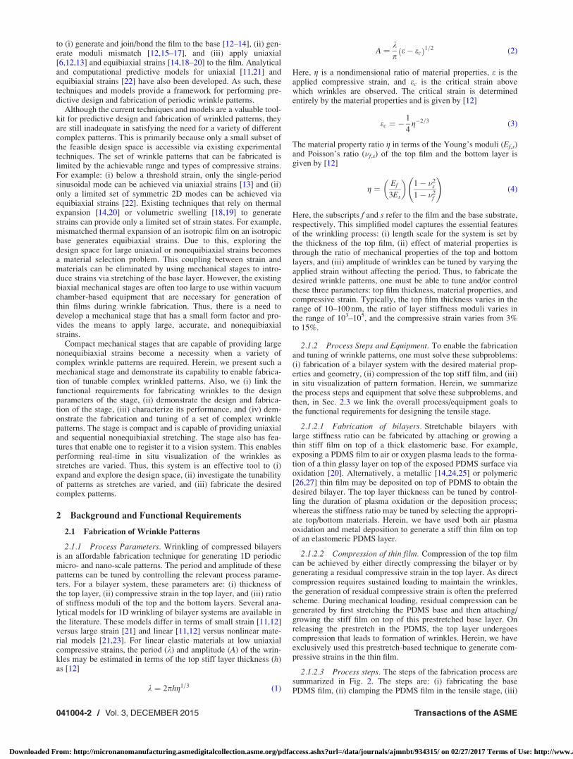
Wrinkles in compressed bilayer systems are formed due tobuckling-based instabilities. The mechanism of wrinkling is simi-lar to Euler buckling of columns under compression [11]. A sche-matic of the process is illustrated in Fig. 1. Essential elements ofthese bilayer systems are: (i) a film that is thin relative to the base,(ii) mismatch in the elastic moduli of the film and the base withthe film being stiffer than the base, and (iii) loading conditionsthat generate in-plane compressive strain in the film. In such sys-tems, the state of pure compression becomes unstable beyond acritical strain and wrinkles are formed via periodic bending of thefilm/base. The period of wrinkles is determined by the competingdependence of strain energy on period in the film versus in thebase. Several different techniques have been developed in the past
Fig. 1 Schematic of wrinkle formation via compression of abilayer film
1Present address: Materials Engineering Division, Lawrence Livermore NationalLaboratory, P.O. Box 808, L-781, Livermore, CA 94551.
2Corresponding author.Contributed by the Manufacturing Engineering Division of ASME for publication
in the JOURNAL OF MICRO- AND NANO-MANUFACTURING. Manuscript received December23, 2014; final manuscript received August 18, 2015; published online September14, 2015. Assoc. Editor: Stefan Dimov.
Journal of Micro- and Nano-Manufacturing DECEMBER 2015, Vol. 3 / 041004-1Copyright VC 2015 by ASME
Downloaded From: http://micronanomanufacturing.asmedigitalcollection.asme.org/pdfaccess.ashx?url=/data/journals/ajmnbt/934315/ on 02/27/2017 Terms of Use: http://www.asme.org/about-asme/terms-of-use
to (i) generate and join/bond the film to the base [12–14], (ii) gen-erate moduli mismatch [12,15–17], and (iii) apply uniaxial[6,12,13] and equibiaxial strains [14,18–20] to the film. Analyticaland computational predictive models for uniaxial [11,21] andequibiaxial strains [22] have also been developed. As such, thesetechniques and models provide a framework for performing pre-dictive design and fabrication of periodic wrinkle patterns.
Although the current techniques and models are a valuable tool-kit for predictive design and fabrication of wrinkled patterns, theyare still inadequate in satisfying the need for a variety of differentcomplex patterns. This is primarily because only a small subset ofthe feasible design space is accessible via existing experimentaltechniques. The set of wrinkle patterns that can be fabricated islimited by the achievable range and types of compressive strains.For example: (i) below a threshold strain, only the single-periodsinusoidal mode can be achieved via uniaxial strains [13] and (ii)only a limited set of symmetric 2D modes can be achieved viaequibiaxial strains [22]. Existing techniques that rely on thermalexpansion [14,20] or volumetric swelling [18,19] to generatestrains can provide only a limited set of strain states. For example,mismatched thermal expansion of an isotropic film on an isotropicbase generates equibiaxial strains. Due to this, exploring thedesign space for large uniaxial or nonequibiaxial strains becomesa material selection problem. This coupling between strain andmaterials can be eliminated by using mechanical stages to intro-duce strains via stretching of the base layer. However, the existingbiaxial mechanical stages are often too large to use within vacuumchamber-based equipment that are necessary for generation ofthin films during wrinkle fabrication. Thus, there is a need todevelop a mechanical stage that has a small form factor and pro-vides the means to apply large, accurate, and nonequibiaxialstrains.
Compact mechanical stages that are capable of providing largenonequibiaxial strains become a necessity when a variety ofcomplex wrinkle patterns are required. Herein, we present such amechanical stage and demonstrate its capability to enable fabrica-tion of tunable complex wrinkled patterns. Also, we (i) link thefunctional requirements for fabricating wrinkles to the designparameters of the stage, (ii) demonstrate the design and fabrica-tion of the stage, (iii) characterize its performance, and (iv) dem-onstrate the fabrication and tuning of a set of complex wrinklepatterns. The stage is compact and is capable of providing uniaxialand sequential nonequibiaxial stretching. The stage also has fea-tures that enable one to register it to a vision system. This enablesperforming real-time in situ visualization of the wrinkles asstretches are varied. Thus, this system is an effective tool to (i)expand and explore the design space, (ii) investigate the tunabilityof patterns as stretches are varied, and (iii) fabricate the desiredcomplex patterns.
2 Background and Functional Requirements
2.1 Fabrication of Wrinkle Patterns
2.1.1 Process Parameters. Wrinkling of compressed bilayersis an affordable fabrication technique for generating 1D periodicmicro- and nano-scale patterns. The period and amplitude of thesepatterns can be tuned by controlling the relevant process parame-ters. For a bilayer system, these parameters are: (i) thickness ofthe top layer, (ii) compressive strain in the top layer, and (iii) ratioof stiffness moduli of the top and the bottom layers. Several ana-lytical models for 1D wrinkling of bilayer systems are available inthe literature. These models differ in terms of small strain [11,12]versus large strain [21] and linear [11,12] versus nonlinear mate-rial models [21,23]. For linear elastic materials at low uniaxialcompressive strains, the period (k) and amplitude (A) of the wrin-kles may be estimated in terms of the top stiff layer thickness (h)as [12]
k ¼ 2phg1=3 (1)
A ¼ kp
e� ecð Þ1=2 (2)
Here, g is a nondimensional ratio of material properties, e is theapplied compressive strain, and ec is the critical strain abovewhich wrinkles are observed. The critical strain is determinedentirely by the material properties and is given by [12]
ec ¼ �1
4g�2=3 (3)
The material property ratio g in terms of the Young’s moduli (Ef,s)and Poisson’s ratio (�f,s) of the top film and the bottom layer isgiven by [12]
g ¼ Ef
3Es
� �1� �2
s
1� �2f
!(4)
Here, the subscripts f and s refer to the film and the base substrate,respectively. This simplified model captures the essential featuresof the wrinkling process: (i) length scale for the system is set bythe thickness of the top film, (ii) effect of material properties isthrough the ratio of mechanical properties of the top and bottomlayers, and (iii) amplitude of wrinkles can be tuned by varying theapplied strain without affecting the period. Thus, to fabricate thedesired wrinkle patterns, one must be able to tune and/or controlthese three parameters: top film thickness, material properties, andcompressive strain. Typically, the top film thickness varies in therange of 10–100 nm, the ratio of layer stiffness moduli varies inthe range of 103–105, and the compressive strain varies from 3%to 15%.
2.1.2 Process Steps and Equipment. To enable the fabricationand tuning of wrinkle patterns, one must solve these subproblems:(i) fabrication of a bilayer system with the desired material prop-erties and geometry, (ii) compression of the top stiff film, and (iii)in situ visualization of pattern formation. Herein, we summarizethe process steps and equipment that solve these subproblems, andthen, in Sec. 2.3 we link the overall process/equipment goals tothe functional requirements for designing the tensile stage.
2.1.2.1 Fabrication of bilayers. Stretchable bilayers withlarge stiffness ratio can be fabricated by attaching or growing athin stiff film on top of a thick elastomeric base. For example,exposing a PDMS film to air or oxygen plasma leads to the forma-tion of a thin glassy layer on top of the exposed PDMS surface viaoxidation [20]. Alternatively, a metallic [14,24,25] or polymeric[26,27] thin film may be deposited on top of PDMS to obtain thedesired bilayer. The top layer thickness can be tuned by control-ling the duration of plasma oxidation or the deposition process;whereas the stiffness ratio may be tuned by selecting the appropri-ate top/bottom materials. Herein, we have used both air plasmaoxidation and metal deposition to generate a stiff thin film on topof an elastomeric PDMS layer.
2.1.2.2 Compression of thin film. Compression of the top filmcan be achieved by either directly compressing the bilayer or bygenerating a residual compressive strain in the top layer. As directcompression requires sustained loading to maintain the wrinkles,the generation of residual compressive strain is often the preferredscheme. During mechanical loading, residual compression can begenerated by first stretching the PDMS base and then attaching/growing the stiff film on top of this prestretched base layer. Onreleasing the prestretch in the PDMS, the top layer undergoescompression that leads to formation of wrinkles. Herein, we haveexclusively used this prestretch-based technique to generate com-pressive strains in the thin film.
2.1.2.3 Process steps. The steps of the fabrication process aresummarized in Fig. 2. The steps are: (i) fabricating the basePDMS film, (ii) clamping the PDMS film in the tensile stage, (iii)
041004-2 / Vol. 3, DECEMBER 2015 Transactions of the ASME
Downloaded From: http://micronanomanufacturing.asmedigitalcollection.asme.org/pdfaccess.ashx?url=/data/journals/ajmnbt/934315/ on 02/27/2017 Terms of Use: http://www.asme.org/about-asme/terms-of-use
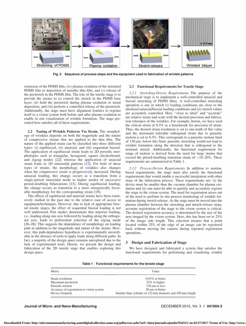
extension of the PDMS film, (iv) plasma oxidation of the stretchedPDMS film or deposition of metallic thin film, and (v) release ofthe prestretch in the PDMS film. The role of the tensile stage is toprovide the means to (i) control the stretch in the PDMS baselayer, (ii) hold the prestretch during plasma oxidation or metaldeposition, and (iii) perform a controlled release of the prestretch.Additionally, the stage must have alignment features to registeritself to a vision system both before and after plasma oxidation toenable in situ visualization of wrinkle formation. The stage pre-sented here satisfies all of these requirements.
2.2 Tuning of Wrinkle Patterns Via Strain. The morphol-ogy of wrinkles depends on both the magnitude and the natureof compressive strains that are applied to the thin film. Thenature of the applied strain can be classified into three differenttypes: (i) equibiaxial, (ii) uniaxial, and (iii) sequential biaxial.The application of equibiaxial strain leads to 2D periodic mor-phologies such as triangular, hexagonal, square checkerboard,and zigzag modes [22] whereas the application of uniaxialstrain leads to 1D sinusoidal patterns [12]. For both of thesetypes of strains, the morphology of wrinkles also changeswhen the compressive strain is progressively increased. Duringuniaxial loading, this change occurs as a transition from asingle-period sinusoidal mode to higher modes of successiveperiod-doubling bifurcations [13]. During equibiaxial loading,the change occurs as transition to a more energetically favor-able morphology for the corresponding strain [19].
The effects of equibiaxial and uniaxial strains have been exten-sively studied in the past due to the relative ease of access toequipment/techniques. However, due to lack of appropriate biax-ial tensile stages, the effect of sequential biaxial loading is notwell understood. Past studies demonstrate that stepwise loading,i.e., loading along one axis followed by loading along the orthogo-nal axis, leads to preferential selection of the zigzag mode[26–28]. This suggests the dependence of morphology on loadingpath in addition to the magnitude and nature of the strains. How-ever, this path-dependence hypothesis is experimentally unverifi-able in the absence of tools to apply loads along different paths. Infact, a majority of the design space remains unexplored due to thelack of experimental tools. Herein, we present the design andfabrication of the 2D tensile stage that enables exploring thisdesign space.
2.3 Functional Requirements for Tensile Stage
2.3.1 Stretching-Driven Requirements. The purpose of themechanical stage is to implement a well-controlled uniaxial andbiaxial stretching of PDMS films. A well-controlled stretchingoperation is one in which (i) loading conditions are close to theidealized uniaxial/biaxial loading conditions and (ii) stretch valuesare accurately controlled. Here, “close to ideal” and “accurate”are relative terms and scale with the desired precision and fabrica-tion tolerance of the wrinkles. For example, herein, we have usedthe critical strain of 0.3% as a benchmark for precision of strain.Thus, the desired strain resolution is set to one-tenth of this valueand the maximum tolerable orthogonal strain due to parasiticmotion is set to 0.3%. This corresponds to a parasitic motion limitof 130 lm; below this limit, parasitic stretching would not lead towrinkle formation along the direction that is orthogonal to thenominal stretch. Additionally, the functional requirement forrange of motion is derived from the need for large strains thatexceed the period-doubling transition strain of �18–20%. Theserequirements are summarized in Table 1.
2.3.2 Process-Driven Requirements. In addition to motion-based requirements, the stage must also satisfy the functionalrequirements that would enable a successful integration with othersteps of the fabrication process. These requirements are: (i) thedevice must be smaller than the vacuum chamber for plasma oxi-dation and (ii) one must be able to quickly and accurately registerthe stage to the vision system. The need for registration arises outof the need to perform in situ process monitoring of wrinkle for-mation during stretch release. As the stage must be moved into theplasma chamber between the stretching and stretch-release steps,accurate registration of the stage to the vision system is critical.The desired registration accuracy is determined by the size of thearea imaged by the vision system. Here, this has been set to 25%of the image side length. This selection ensures that a pointlocated within 25% of the edge of an image can be registeredback without moving the camera during repeated registrationoperations.
3 Design and Fabrication of Stage
We have designed and fabricated a system that satisfies thefunctional requirements for performing and visualizing wrinkle
Fig. 2 Sequence of process steps and the equipment used in fabrication of wrinkle patterns
Table 1 Functional requirements for the tensile stage
Metric Value
Strain resolution 0.03% or betterMaximum prestretch 25% or higherParasitic motion 130 lm or lessAccuracy of registration to vision system 30 lm or betterDevice footprint Smaller than cylinder of 122 mm diameter and 450 mm length
Journal of Micro- and Nano-Manufacturing DECEMBER 2015, Vol. 3 / 041004-3
Downloaded From: http://micronanomanufacturing.asmedigitalcollection.asme.org/pdfaccess.ashx?url=/data/journals/ajmnbt/934315/ on 02/27/2017 Terms of Use: http://www.asme.org/about-asme/terms-of-use
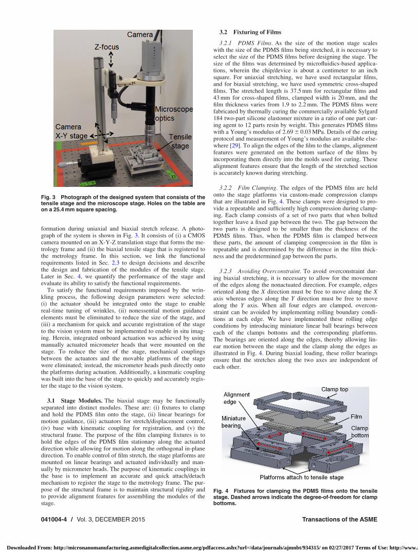
formation during uniaxial and biaxial stretch release. A photo-graph of the system is shown in Fig. 3. It consists of (i) a CMOScamera mounted on an X-Y-Z translation stage that forms the me-trology frame and (ii) the biaxial tensile stage that is registered tothe metrology frame. In this section, we link the functionalrequirements listed in Sec. 2.3 to design decisions and describethe design and fabrication of the modules of the tensile stage.Later in Sec. 4, we quantify the performance of the stage andevaluate its ability to satisfy the functional requirements.
To satisfy the functional requirements imposed by the wrin-kling process, the following design parameters were selected:(i) the actuator should be integrated onto the stage to enablereal-time tuning of wrinkles, (ii) nonessential motion guidanceelements must be eliminated to reduce the size of the stage, and(iii) a mechanism for quick and accurate registration of the stageto the vision system must be implemented to enable in situ imag-ing. Herein, integrated onboard actuation was achieved by usingmanually actuated micrometer heads that were mounted on thestage. To reduce the size of the stage, mechanical couplingsbetween the actuators and the movable platforms of the stagewere eliminated; instead, the micrometer heads push directly ontothe platforms during actuation. Additionally, a kinematic couplingwas built into the base of the stage to quickly and accurately regis-ter the stage to the vision system.
3.1 Stage Modules. The biaxial stage may be functionallyseparated into distinct modules. These are: (i) fixtures to clampand hold the PDMS film onto the stage, (ii) linear bearings formotion guidance, (iii) actuators for stretch/displacement control,(iv) base with kinematic coupling for registration, and (v) thestructural frame. The purpose of the film clamping fixtures is tohold the edges of the PDMS film stationary along the actuateddirection while allowing for motion along the orthogonal in-planedirection. To enable control of film stretch, the stage platforms aremounted on linear bearings and actuated individually and man-ually by micrometer heads. The purpose of kinematic couplings inthe base is to implement an accurate and quick attach/detachmechanism to register the stage to the metrology frame. The pur-pose of the structural frame is to maintain structural rigidity andto provide alignment features for assembling the modules of thestage.
3.2 Fixturing of Films
3.2.1 PDMS Films. As the size of the motion stage scaleswith the size of the PDMS films being stretched, it is necessary toselect the size of the PDMS films before designing the stage. Thesize of the films was determined by microfluidics-based applica-tions, wherein the chip/device is about a centimeter to an inchsquare. For uniaxial stretching, we have used rectangular films,and for biaxial stretching, we have used symmetric cross-shapedfilms. The stretched length is 37.5 mm for rectangular films and43 mm for cross-shaped films, clamped width is 20 mm, and thefilm thickness varies from 1.9 to 2.2 mm. The PDMS films werefabricated by thermally curing the commercially available Sylgard184 two-part silicone elastomer mixture in a ratio of one part cur-ing agent to 12 parts resin by weight. This generates PDMS filmswith a Young’s modulus of 2.69 6 0.03 MPa. Details of the curingprotocol and measurement of Young’s modulus are available else-where [29]. To align the edges of the film to the clamps, alignmentfeatures were generated on the bottom surface of the films byincorporating them directly into the molds used for curing. Thesealignment features ensure that the length of the stretched sectionis accurately known during stretching.
3.2.2 Film Clamping. The edges of the PDMS film are heldonto the stage platforms via custom-made compression clampsthat are illustrated in Fig. 4. These clamps were designed to pro-vide a repeatable and sufficiently high compression during clamp-ing. Each clamp consists of a set of two parts that when boltedtogether leave a fixed gap between the two. The gap between thetwo parts is designed to be smaller than the thickness of thePDMS films. Thus, when the PDMS film is clamped betweenthese parts, the amount of clamping compression in the film isrepeatable and is determined by the difference in the film thick-ness and the predetermined gap between the parts.
3.2.3 Avoiding Overconstraint. To avoid overconstraint dur-ing biaxial stretching, it is necessary to allow for the movementof the edges along the nonactuated direction. For example, edgesoriented along the X direction must be free to move along the Xaxis whereas edges along the Y direction must be free to movealong the Y axis. When all four edges are clamped, overcon-straint can be avoided by implementing rolling boundary condi-tions at each edge. We have implemented these rolling edgeconditions by introducing miniature linear ball bearings betweeneach of the clamps bottoms and the corresponding platforms.The bearings are oriented along the edges, thereby allowing lin-ear motion between the stage and the clamp along the edges asillustrated in Fig. 4. During biaxial loading, these roller bearingsensure that the stretches along the two axes are independent ofeach other.
Fig. 3 Photograph of the designed system that consists of thetensile stage and the microscope stage. Holes on the table areon a 25.4 mm square spacing.
Fig. 4 Fixtures for clamping the PDMS films onto the tensilestage. Dashed arrows indicate the degree-of-freedom for clampbottoms.
041004-4 / Vol. 3, DECEMBER 2015 Transactions of the ASME
Downloaded From: http://micronanomanufacturing.asmedigitalcollection.asme.org/pdfaccess.ashx?url=/data/journals/ajmnbt/934315/ on 02/27/2017 Terms of Use: http://www.asme.org/about-asme/terms-of-use
3.3 Motion Stage
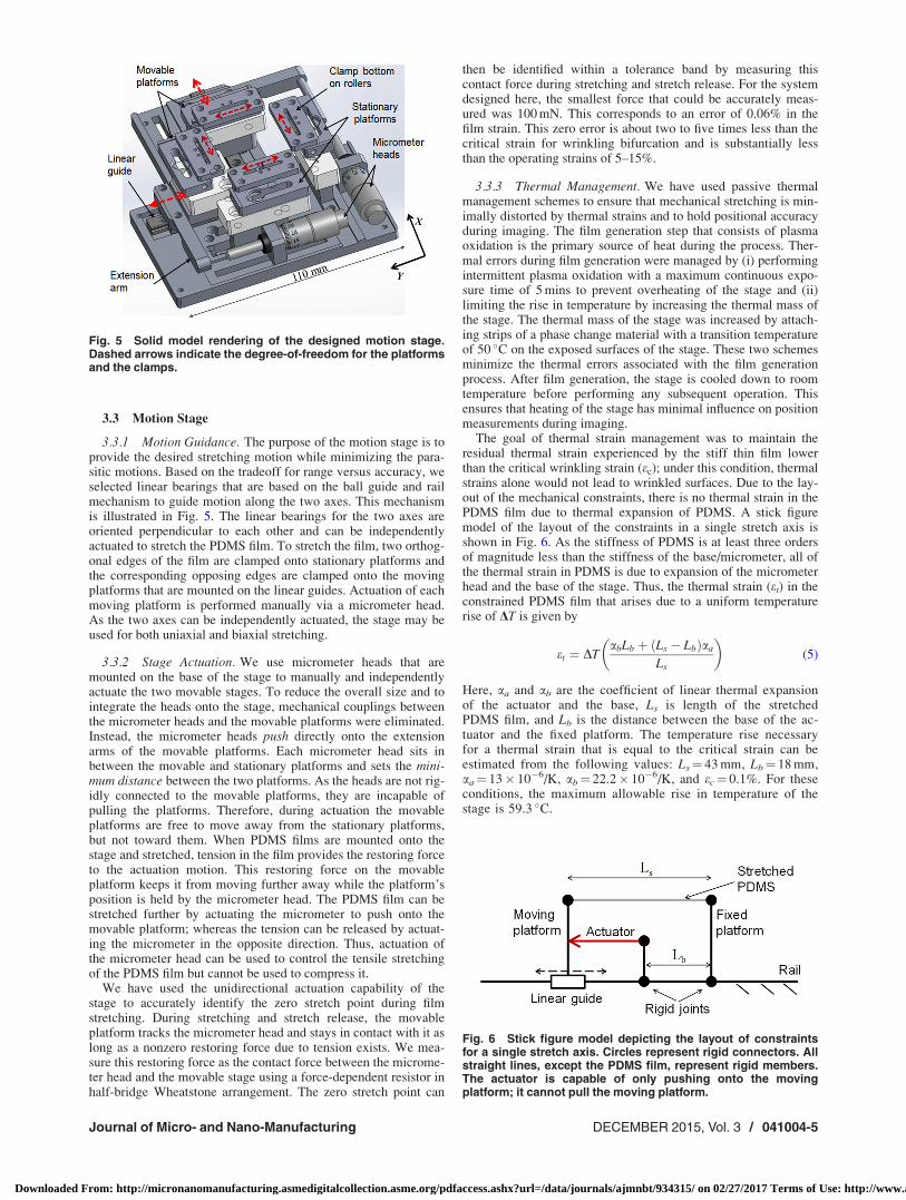
3.3.1 Motion Guidance. The purpose of the motion stage is toprovide the desired stretching motion while minimizing the para-sitic motions. Based on the tradeoff for range versus accuracy, weselected linear bearings that are based on the ball guide and railmechanism to guide motion along the two axes. This mechanismis illustrated in Fig. 5. The linear bearings for the two axes areoriented perpendicular to each other and can be independentlyactuated to stretch the PDMS film. To stretch the film, two orthog-onal edges of the film are clamped onto stationary platforms andthe corresponding opposing edges are clamped onto the movingplatforms that are mounted on the linear guides. Actuation of eachmoving platform is performed manually via a micrometer head.As the two axes can be independently actuated, the stage may beused for both uniaxial and biaxial stretching.
3.3.2 Stage Actuation. We use micrometer heads that aremounted on the base of the stage to manually and independentlyactuate the two movable stages. To reduce the overall size and tointegrate the heads onto the stage, mechanical couplings betweenthe micrometer heads and the movable platforms were eliminated.Instead, the micrometer heads push directly onto the extensionarms of the movable platforms. Each micrometer head sits inbetween the movable and stationary platforms and sets the mini-mum distance between the two platforms. As the heads are not rig-idly connected to the movable platforms, they are incapable ofpulling the platforms. Therefore, during actuation the movableplatforms are free to move away from the stationary platforms,but not toward them. When PDMS films are mounted onto thestage and stretched, tension in the film provides the restoring forceto the actuation motion. This restoring force on the movableplatform keeps it from moving further away while the platform’sposition is held by the micrometer head. The PDMS film can bestretched further by actuating the micrometer to push onto themovable platform; whereas the tension can be released by actuat-ing the micrometer in the opposite direction. Thus, actuation ofthe micrometer head can be used to control the tensile stretchingof the PDMS film but cannot be used to compress it.
We have used the unidirectional actuation capability of thestage to accurately identify the zero stretch point during filmstretching. During stretching and stretch release, the movableplatform tracks the micrometer head and stays in contact with it aslong as a nonzero restoring force due to tension exists. We mea-sure this restoring force as the contact force between the microme-ter head and the movable stage using a force-dependent resistor inhalf-bridge Wheatstone arrangement. The zero stretch point can
then be identified within a tolerance band by measuring thiscontact force during stretching and stretch release. For the systemdesigned here, the smallest force that could be accurately meas-ured was 100 mN. This corresponds to an error of 0.06% in thefilm strain. This zero error is about two to five times less than thecritical strain for wrinkling bifurcation and is substantially lessthan the operating strains of 5–15%.
3.3.3 Thermal Management. We have used passive thermalmanagement schemes to ensure that mechanical stretching is min-imally distorted by thermal strains and to hold positional accuracyduring imaging. The film generation step that consists of plasmaoxidation is the primary source of heat during the process. Ther-mal errors during film generation were managed by (i) performingintermittent plasma oxidation with a maximum continuous expo-sure time of 5 mins to prevent overheating of the stage and (ii)limiting the rise in temperature by increasing the thermal mass ofthe stage. The thermal mass of the stage was increased by attach-ing strips of a phase change material with a transition temperatureof 50 �C on the exposed surfaces of the stage. These two schemesminimize the thermal errors associated with the film generationprocess. After film generation, the stage is cooled down to roomtemperature before performing any subsequent operation. Thisensures that heating of the stage has minimal influence on positionmeasurements during imaging.
The goal of thermal strain management was to maintain theresidual thermal strain experienced by the stiff thin film lowerthan the critical wrinkling strain (ec); under this condition, thermalstrains alone would not lead to wrinkled surfaces. Due to the lay-out of the mechanical constraints, there is no thermal strain in thePDMS film due to thermal expansion of PDMS. A stick figuremodel of the layout of the constraints in a single stretch axis isshown in Fig. 6. As the stiffness of PDMS is at least three ordersof magnitude less than the stiffness of the base/micrometer, all ofthe thermal strain in PDMS is due to expansion of the micrometerhead and the base of the stage. Thus, the thermal strain (et) in theconstrained PDMS film that arises due to a uniform temperaturerise of DT is given by
et ¼ DTabLb þ Ls � Lbð Þaa
Ls
� �(5)
Here, aa and ab are the coefficient of linear thermal expansionof the actuator and the base, Ls is length of the stretchedPDMS film, and Lb is the distance between the base of the ac-tuator and the fixed platform. The temperature rise necessaryfor a thermal strain that is equal to the critical strain can beestimated from the following values: Ls¼ 43 mm, Lb¼ 18 mm,aa¼ 13� 10�6/K, ab¼ 22.2� 10�6/K, and ec¼ 0.1%. For theseconditions, the maximum allowable rise in temperature of thestage is 59.3 �C.
Fig. 5 Solid model rendering of the designed motion stage.Dashed arrows indicate the degree-of-freedom for the platformsand the clamps.
Fig. 6 Stick figure model depicting the layout of constraintsfor a single stretch axis. Circles represent rigid connectors. Allstraight lines, except the PDMS film, represent rigid members.The actuator is capable of only pushing onto the movingplatform; it cannot pull the moving platform.
Journal of Micro- and Nano-Manufacturing DECEMBER 2015, Vol. 3 / 041004-5
Downloaded From: http://micronanomanufacturing.asmedigitalcollection.asme.org/pdfaccess.ashx?url=/data/journals/ajmnbt/934315/ on 02/27/2017 Terms of Use: http://www.asme.org/about-asme/terms-of-use
3.4 Vision System. We have assembled a custom microscopeto satisfy the need for in situ visualization of wrinkle formation.The microscope consists of (i) optics for image magnification, (ii)an illuminator for coaxial illumination, (iii) a 5.0 MP CMOS cam-era (PixeLINK PL-B777U) to record the magnified image, and(iv) a manually actuated X-Y-Z stage to scan the sample surfaceand to focus the microscope. As this microscope uses reflectedlight instead of transmitted light for imaging, there are no compo-nents below the lens. This allows for the tensile stage to be freelypositioned within the space below the microscope lens. The ten-sile stage was registered to the metrology frame by registering itto the fixed base of the X-Y-Z stage on the microscope. Themicroscope has a numerical aperture of 0.42, a working distanceof 20 mm, a depth-of-field of 4 lm, and a lateral resolution of0.86 lm. It enables recording grayscale reflected-light images ofthe wrinkled surface with a magnification of 35.1� and a capturedarea of 163 lm� 122 lm.
3.5 Registration of Stage to Vision System. We have used a“3-ball and V-groove” kinematic coupling to implement a quickand repeatable attach/detach mechanism for precise registration ofthe stage to the metrology frame. Kinematic couplings have beensuccessfully used in the past to achieve registration with submi-cron repeatability for precision fixturing [30,31]. In this system,one-half of the coupling is aligned and rigidly attached to the me-trology frame whereas the other half is aligned and attached to thestage. Preload to the coupling is provided by a pair of permanentmagnets that are attached to the two-halves of the coupling. Thus,the stage can be registered to the vision system by engaging thetwo-halves of the coupling. Registration of the stage to the metrol-ogy frame involves aligning and locating the coordinate frames ofthe two systems with respect to each other. To enable quick regis-tration, we perform alignment in two stages. First, we perform aninitial alignment to achieve these registration requirements; then,we use the kinematic couplings to maintain the registration duringrepeated engagement–disengagement of the tensile stage from themetrology frame.
4 Performance of Stage
The performance of the tensile stage is summarized in Table 2.Herein, we (i) quantify the accuracy of the applied strain and theaccuracy of registration and (ii) discuss the factors that affect theperformance of the stage.
4.1 Accuracy of Strain
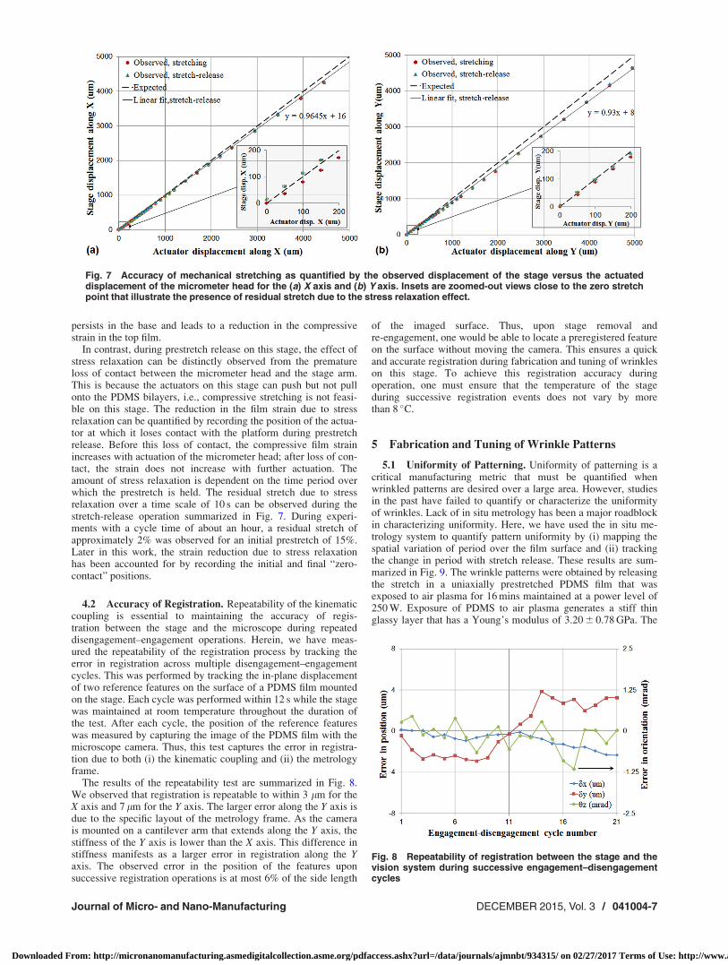
4.1.1 Mechanical Stretching. Accuracy of mechanical stretch-ing is critical for an accurate control of the compressive strains inthe film. Herein, we have measured and calibrated the displace-ment of the movable platforms during actuation. For calibrationof each axis, a rectangular PDMS film was first mounted on thestage and then stretched by actuating the micrometer head; thiswas followed by reversing the direction of actuation to release theprestretch. The in-plane displacement of the movable stage wasmeasured with a set of two Mitutoyo digital dial indicators
(Digimatic Series 543) that had a resolution of 1 lm and an accu-racy of 63 lm. The indicators were aligned along and perpendic-ular to the direction of actuation. The results of thesemeasurements are summarized in Fig. 7.
Under ideal conditions, the displacements of the platform andthe actuator must be identical. However, the displacement of theplatform was observed to be lower than that of the actuatorbecause of the compliance in the parts between the platform andthe actuator. This compliance was higher for the Y axis than the Xaxis due to a force sensor pad that was present on the Y axis butnot on the X axis. Later in this work, the calibration curves gener-ated in Fig. 7 have been used to correct for this reduction in straindue to machine compliance. The corresponding parasitic displace-ment of the stages along the in-plane orthogonal direction is lim-ited to 56 lm for the X axis and 65 lm for the Y axis over a travelspan of 5 mm. This verifies that the stage motion along the indi-vidual axis is indeed uniaxial over the travel distance.
4.1.2 Thermal Strains. The purpose of the passive thermalmanagement scheme was to ensure that the thermal strains aresmaller than the critical strain for wrinkling. To verify the effec-tiveness of this scheme, temperature at various spots on the stagewas measured after an unstretched PDMS film was exposed to airplasma for 90 mins. The exposure cycle consisted of 5 mins of con-tinuous exposure followed by a 5-min interval during which theplasma was switched off. Immediately after cumulative plasma ex-posure of 90 mins, temperature at various spots on the stage wasmeasured using a thermocouple probe. The temperature wasobserved to vary within the range of 50–60 �C over the surface ofthe stage. The maximum temperature was observed on the clampsand the minimum temperature was observed on the exposed sur-face of the extension arm. The surface of the exposed PDMS filmwas examined under an atomic force microscope (AFM) to verifythat no wrinkles were formed under thermal strains, i.e., thethermal strains were lower than the critical strain. Under theAFM microscope, a flat nonwrinkled surface was observed thathad a surface roughness (Ra) of 3.5 nm over a scanned area of30 lm� 30 lm. This justifies the approximation that the thermalstrain on this tensile stage during plasma oxidation is negligible ascompared to the strain due to mechanical stretching.
4.1.3 Stress Relaxation in PDMS. Due to the viscoelastic ma-terial behavior, the PDMS films exhibit stress relaxation. Thus,when the prestretch in a stretched PDMS film is released, the filmdoes not fully recover back to its original position thereby leadingto a residual stretch. This residual stretch in the PDMS base leadsto a reduction in the compressive strain in the top film. In previousstudies describing the wrinkling of mechanically stretched PDMS,this strain reduction has not been reported and/or accounted for.Although this phenomenon exists in such studies, its observationis hindered by the inability to detect the effect of stress relaxationin displacement-controlled actuation schemes. In such schemes,the PDMS film is “forced back” into the original position duringprestretch release; in this position, the residual stretch in the baseis often released via macroscale curvature of the bilayer. Whensuch a bilayer is unclamped from the stage, the residual stretch
Table 2 Performance of the tensile stage
Metric Value
Film unstretched length 37.5 mm (1D film) and 43 mm (2D film)Displacement resolution 10 lm along each axisStrain resolution 0.027% (1D film) and 0.023% (2D film)Range of motion 13 mm along each axisParasitic motion 65 lmMaximum prestretch, nominal 34.7% (1D film) and 30.2% (2D film)Maximum prestretch, compliance corrected 33.5% (1D film), 29.2% along X, and 28.1% along Y (2D film)Accuracy of registration to vision system 7 lmDevice footprint 131 mm� 110 mm� 75 mm
041004-6 / Vol. 3, DECEMBER 2015 Transactions of the ASME
Downloaded From: http://micronanomanufacturing.asmedigitalcollection.asme.org/pdfaccess.ashx?url=/data/journals/ajmnbt/934315/ on 02/27/2017 Terms of Use: http://www.asme.org/about-asme/terms-of-use
persists in the base and leads to a reduction in the compressivestrain in the top film.
In contrast, during prestretch release on this stage, the effect ofstress relaxation can be distinctly observed from the prematureloss of contact between the micrometer head and the stage arm.This is because the actuators on this stage can push but not pullonto the PDMS bilayers, i.e., compressive stretching is not feasi-ble on this stage. The reduction in the film strain due to stressrelaxation can be quantified by recording the position of the actua-tor at which it loses contact with the platform during prestretchrelease. Before this loss of contact, the compressive film strainincreases with actuation of the micrometer head; after loss of con-tact, the strain does not increase with further actuation. Theamount of stress relaxation is dependent on the time period overwhich the prestretch is held. The residual stretch due to stressrelaxation over a time scale of 10 s can be observed during thestretch-release operation summarized in Fig. 7. During experi-ments with a cycle time of about an hour, a residual stretch ofapproximately 2% was observed for an initial prestretch of 15%.Later in this work, the strain reduction due to stress relaxationhas been accounted for by recording the initial and final “zero-contact” positions.
4.2 Accuracy of Registration. Repeatability of the kinematiccoupling is essential to maintaining the accuracy of regis-tration between the stage and the microscope during repeateddisengagement–engagement operations. Herein, we have meas-ured the repeatability of the registration process by tracking theerror in registration across multiple disengagement–engagementcycles. This was performed by tracking the in-plane displacementof two reference features on the surface of a PDMS film mountedon the stage. Each cycle was performed within 12 s while the stagewas maintained at room temperature throughout the duration ofthe test. After each cycle, the position of the reference featureswas measured by capturing the image of the PDMS film with themicroscope camera. Thus, this test captures the error in registra-tion due to both (i) the kinematic coupling and (ii) the metrologyframe.
The results of the repeatability test are summarized in Fig. 8.We observed that registration is repeatable to within 3 lm for theX axis and 7 lm for the Y axis. The larger error along the Y axis isdue to the specific layout of the metrology frame. As the camerais mounted on a cantilever arm that extends along the Y axis, thestiffness of the Y axis is lower than the X axis. This difference instiffness manifests as a larger error in registration along the Yaxis. The observed error in the position of the features uponsuccessive registration operations is at most 6% of the side length
of the imaged surface. Thus, upon stage removal andre-engagement, one would be able to locate a preregistered featureon the surface without moving the camera. This ensures a quickand accurate registration during fabrication and tuning of wrinkleson this stage. To achieve this registration accuracy duringoperation, one must ensure that the temperature of the stageduring successive registration events does not vary by morethan 8 �C.
5 Fabrication and Tuning of Wrinkle Patterns
5.1 Uniformity of Patterning. Uniformity of patterning is acritical manufacturing metric that must be quantified whenwrinkled patterns are desired over a large area. However, studiesin the past have failed to quantify or characterize the uniformityof wrinkles. Lack of in situ metrology has been a major roadblockin characterizing uniformity. Here, we have used the in situ me-trology system to quantify pattern uniformity by (i) mapping thespatial variation of period over the film surface and (ii) trackingthe change in period with stretch release. These results are sum-marized in Fig. 9. The wrinkle patterns were obtained by releasingthe stretch in a uniaxially prestretched PDMS film that wasexposed to air plasma for 16 mins maintained at a power level of250 W. Exposure of PDMS to air plasma generates a stiff thinglassy layer that has a Young’s modulus of 3.20 6 0.78 GPa. The
Fig. 7 Accuracy of mechanical stretching as quantified by the observed displacement of the stage versus the actuateddisplacement of the micrometer head for the (a) X axis and (b) Y axis. Insets are zoomed-out views close to the zero stretchpoint that illustrate the presence of residual stretch due to the stress relaxation effect.
Fig. 8 Repeatability of registration between the stage and thevision system during successive engagement–disengagementcycles
Journal of Micro- and Nano-Manufacturing DECEMBER 2015, Vol. 3 / 041004-7
Downloaded From: http://micronanomanufacturing.asmedigitalcollection.asme.org/pdfaccess.ashx?url=/data/journals/ajmnbt/934315/ on 02/27/2017 Terms of Use: http://www.asme.org/about-asme/terms-of-use
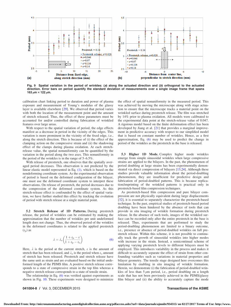
calibration chart linking period to duration and power of plasmaexposure and measurement of Young’s modulus of the glassylayer is available elsewhere [29]. We observed that period varieswith both the location of the measurement point and the amountof stretch released. Thus, the effect of these parameters must beaccounted for and/or controlled during fabrication of wrinkledfeatures over large areas.
With respect to the spatial variation of period, the edge effectsmanifest as a decrease in period in the vicinity of the edges. Thisvariation is more prominent in the vicinity of the fixed edge, i.e.,along the stretch direction. This is because of (i) the effect of theclamping action on the compressive strain and (ii) the shadowingeffect of the clamps during plasma oxidation. At each stretch-release value, the spatial nonuniformity can be quantified by thevariation in the period along the two axes. This nonuniformity inthe period of the wrinkles is in the range of 5–6.5%.
With release of prestretch, one observes that the spatially aver-aged period decreases. This observation is not predicted by thelinear elastic model represented in Eq. (1), which is based on thenondeforming coordinate system. As the experimental observationof period is based on the deformed configuration of the bilayer,one must use the deformed coordinate system to interpret theseobservations. On release of prestretch, the period decreases due tothe compression of the deformed coordinate system. As thisstretch-release effect is confounded by the effect of spatial varia-tion, we have further studied this effect by tracking the evolutionof period with stretch release at a single material point.
5.2 Stretch Release of 1D Patterns. During prestretchrelease, the period of wrinkles can be estimated by making theapproximation that the number of wrinkles per unit undeformedlength does not change. Thus, the observed period of the wrinklesin the deformed coordinates is related to the applied prestretch(ep) as
k ¼ ko1þ ep � e1þ ep � eo
� �(6)
Here, k is the period at the current stretch, e is the amount ofstretch that has been released, and ko is the period when eo amountof stretch has been released. Prestretch and stretch release havethe same unit as strain and are evaluated based on the initial unde-formed length of the PDMS film. A positive stretch release corre-sponds to a state of compressive strain in the top film whereas anegative stretch release corresponds to a state of tensile strain.
The relationship in Eq. (6) was verified against experiments asshown in Fig. 10. These experiments were designed to minimize
the effect of spatial nonuniformity in the measured period. Thiswas achieved by moving the microscope along with stage actua-tion to ensure that the microscope tracks a material point on thewrinkled surface during prestretch release. The film was stretchedby 14% prior to plasma oxidation. All models were calibrated tothe experimental data point at the stretch-release value of 0.047.A rigorous model based on the finite deformation effect has beendeveloped by Jiang et al. [21] that provides a marginal improve-ment in predictive accuracy with respect to our simplified modelthat is based on constant number of wrinkles. Hence, as a firstapproximation, Eq. (6) may be used to predict the change inperiod of the wrinkles as the prestretch in the base is released.
5.3 Higher 1D Mode. Complex higher mode wrinklesemerge from simple sinusoidal wrinkles when large compressivestrains are applied to the bilayers. In the past, the phenomenon ofperiod doubling at large strains has been experimentally demon-strated via direct compression of bilayers [13,24]. Although thesestudies provide valuable information about the period-doublingphenomenon, they are insufficient for predictive design andfabrication of period-doubled patterns. This is because replica-tion/imprinting of the wrinkled patterns is practical only inprestretch-based film compression techniques.
As prestretch-based film compression and pure bilayer com-pression are not physically equivalent during large displacements[32], it is essential to separately characterize the prestretch-basedtechnique. In the past, empirical studies of prestretch-based perioddoubling have been hindered by the absence of tools that canprovide in situ imaging of wrinkle formation during prestretchrelease. In the absence of such tools, images of the wrinkled sur-face can be recorded only after the entire prestretch in the base isreleased. Thus, experiments that are performed to study theperiod-doubling phenomenon are limited to a binary outcome,i.e., presence or absence of period-doubled wrinkles on full pre-stretch release. Within this scheme, it is not possible to continu-ally track the growth of sinusoidal wrinkles into higher modeswith increase in the strain. Instead, a semicontinual scheme ofapplying varying prestretch levels to different bilayers must beemployed. This introduces variability in the process and makes itdifficult to accurately separate the effect of strain from other con-founding variables such as variations in material properties andbilayer geometry. The tensile stage designed here overcomes thislimitation by enabling in situ imaging of wrinkle formation.Herein, we demonstrate (i) the fabrication of period-doubled wrin-kles of less than 5 lm period, i.e., period doubling on a lengthscale that has not been previously achieved in the PDMS/glassyfilm bilayer and (ii) the ability to accurately capture the mode
Fig. 9 Spatial variation in the period of wrinkles: (a) along the actuated direction and (b) orthogonal to the actuateddirection. Error bars on period quantify the standard deviation of measurements over a single image frame that spans163 lm 3 122 lm.
041004-8 / Vol. 3, DECEMBER 2015 Transactions of the ASME
Downloaded From: http://micronanomanufacturing.asmedigitalcollection.asme.org/pdfaccess.ashx?url=/data/journals/ajmnbt/934315/ on 02/27/2017 Terms of Use: http://www.asme.org/about-asme/terms-of-use
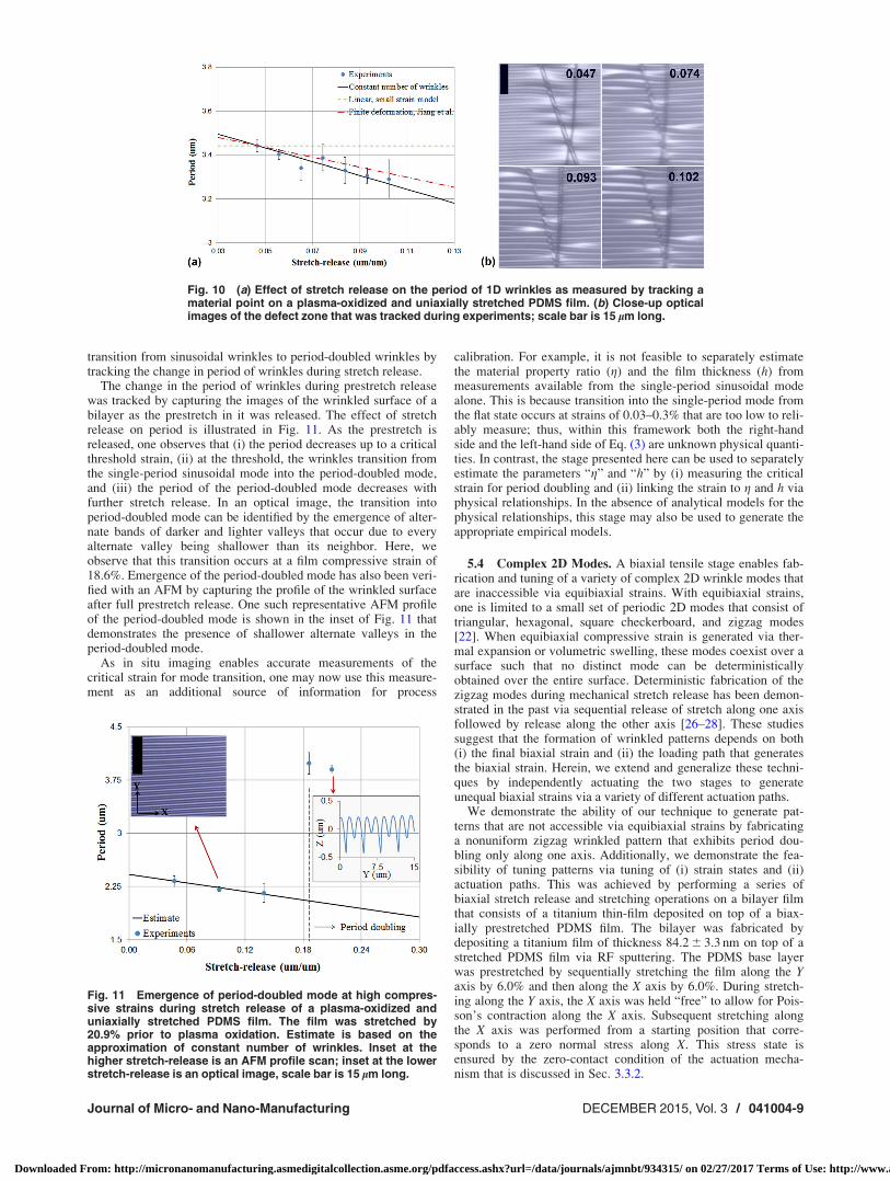
transition from sinusoidal wrinkles to period-doubled wrinkles bytracking the change in period of wrinkles during stretch release.
The change in the period of wrinkles during prestretch releasewas tracked by capturing the images of the wrinkled surface of abilayer as the prestretch in it was released. The effect of stretchrelease on period is illustrated in Fig. 11. As the prestretch isreleased, one observes that (i) the period decreases up to a criticalthreshold strain, (ii) at the threshold, the wrinkles transition fromthe single-period sinusoidal mode into the period-doubled mode,and (iii) the period of the period-doubled mode decreases withfurther stretch release. In an optical image, the transition intoperiod-doubled mode can be identified by the emergence of alter-nate bands of darker and lighter valleys that occur due to everyalternate valley being shallower than its neighbor. Here, weobserve that this transition occurs at a film compressive strain of18.6%. Emergence of the period-doubled mode has also been veri-fied with an AFM by capturing the profile of the wrinkled surfaceafter full prestretch release. One such representative AFM profileof the period-doubled mode is shown in the inset of Fig. 11 thatdemonstrates the presence of shallower alternate valleys in theperiod-doubled mode.
As in situ imaging enables accurate measurements of thecritical strain for mode transition, one may now use this measure-ment as an additional source of information for process
calibration. For example, it is not feasible to separately estimatethe material property ratio (g) and the film thickness (h) frommeasurements available from the single-period sinusoidal modealone. This is because transition into the single-period mode fromthe flat state occurs at strains of 0.03–0.3% that are too low to reli-ably measure; thus, within this framework both the right-handside and the left-hand side of Eq. (3) are unknown physical quanti-ties. In contrast, the stage presented here can be used to separatelyestimate the parameters “g” and “h” by (i) measuring the criticalstrain for period doubling and (ii) linking the strain to g and h viaphysical relationships. In the absence of analytical models for thephysical relationships, this stage may also be used to generate theappropriate empirical models.
5.4 Complex 2D Modes. A biaxial tensile stage enables fab-rication and tuning of a variety of complex 2D wrinkle modes thatare inaccessible via equibiaxial strains. With equibiaxial strains,one is limited to a small set of periodic 2D modes that consist oftriangular, hexagonal, square checkerboard, and zigzag modes[22]. When equibiaxial compressive strain is generated via ther-mal expansion or volumetric swelling, these modes coexist over asurface such that no distinct mode can be deterministicallyobtained over the entire surface. Deterministic fabrication of thezigzag modes during mechanical stretch release has been demon-strated in the past via sequential release of stretch along one axisfollowed by release along the other axis [26–28]. These studiessuggest that the formation of wrinkled patterns depends on both(i) the final biaxial strain and (ii) the loading path that generatesthe biaxial strain. Herein, we extend and generalize these techni-ques by independently actuating the two stages to generateunequal biaxial strains via a variety of different actuation paths.
We demonstrate the ability of our technique to generate pat-terns that are not accessible via equibiaxial strains by fabricatinga nonuniform zigzag wrinkled pattern that exhibits period dou-bling only along one axis. Additionally, we demonstrate the fea-sibility of tuning patterns via tuning of (i) strain states and (ii)actuation paths. This was achieved by performing a series ofbiaxial stretch release and stretching operations on a bilayer filmthat consists of a titanium thin-film deposited on top of a biax-ially prestretched PDMS film. The bilayer was fabricated bydepositing a titanium film of thickness 84.2 6 3.3 nm on top of astretched PDMS film via RF sputtering. The PDMS base layerwas prestretched by sequentially stretching the film along the Yaxis by 6.0% and then along the X axis by 6.0%. During stretch-ing along the Y axis, the X axis was held “free” to allow for Pois-son’s contraction along the X axis. Subsequent stretching alongthe X axis was performed from a starting position that corre-sponds to a zero normal stress along X. This stress state isensured by the zero-contact condition of the actuation mecha-nism that is discussed in Sec. 3.3.2.
Fig. 10 (a) Effect of stretch release on the period of 1D wrinkles as measured by tracking amaterial point on a plasma-oxidized and uniaxially stretched PDMS film. (b) Close-up opticalimages of the defect zone that was tracked during experiments; scale bar is 15 lm long.
Fig. 11 Emergence of period-doubled mode at high compres-sive strains during stretch release of a plasma-oxidized anduniaxially stretched PDMS film. The film was stretched by20.9% prior to plasma oxidation. Estimate is based on theapproximation of constant number of wrinkles. Inset at thehigher stretch-release is an AFM profile scan; inset at the lowerstretch-release is an optical image, scale bar is 15 lm long.
Journal of Micro- and Nano-Manufacturing DECEMBER 2015, Vol. 3 / 041004-9
Downloaded From: http://micronanomanufacturing.asmedigitalcollection.asme.org/pdfaccess.ashx?url=/data/journals/ajmnbt/934315/ on 02/27/2017 Terms of Use: http://www.asme.org/about-asme/terms-of-use
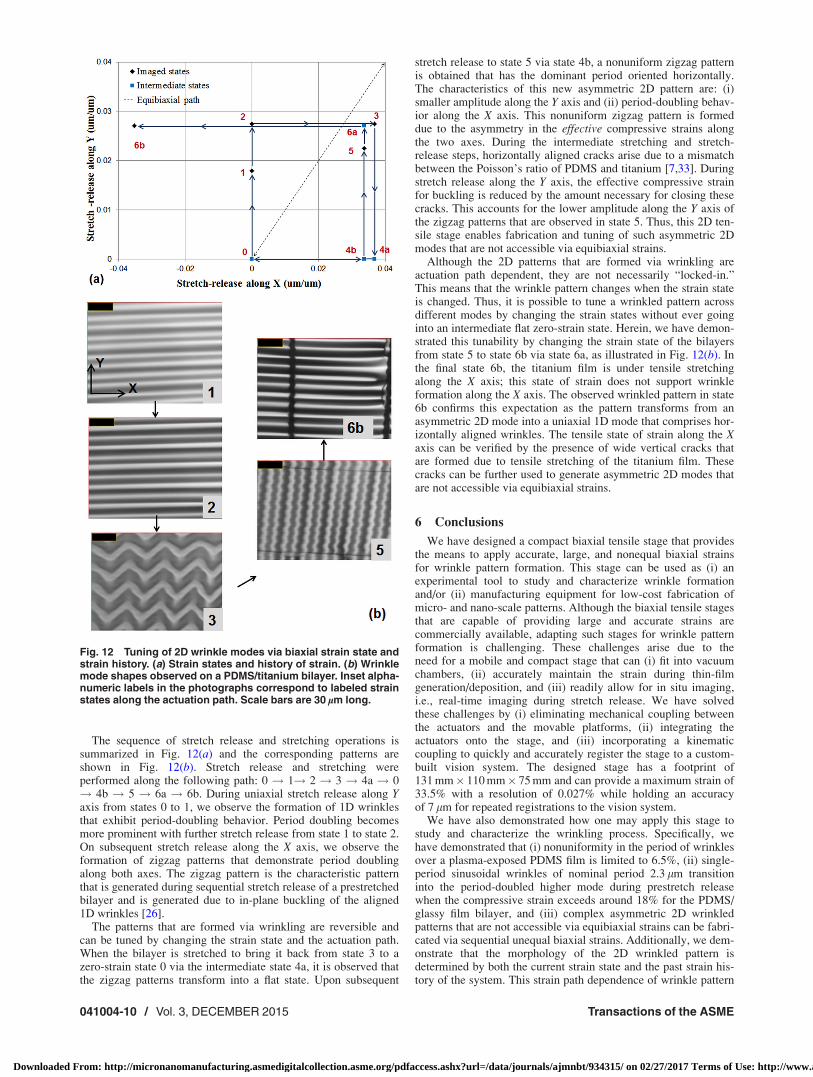
The sequence of stretch release and stretching operations issummarized in Fig. 12(a) and the corresponding patterns areshown in Fig. 12(b). Stretch release and stretching wereperformed along the following path: 0 ! 1! 2 ! 3 ! 4a ! 0! 4b ! 5 ! 6a ! 6b. During uniaxial stretch release along Yaxis from states 0 to 1, we observe the formation of 1D wrinklesthat exhibit period-doubling behavior. Period doubling becomesmore prominent with further stretch release from state 1 to state 2.On subsequent stretch release along the X axis, we observe theformation of zigzag patterns that demonstrate period doublingalong both axes. The zigzag pattern is the characteristic patternthat is generated during sequential stretch release of a prestretchedbilayer and is generated due to in-plane buckling of the aligned1D wrinkles [26].
The patterns that are formed via wrinkling are reversible andcan be tuned by changing the strain state and the actuation path.When the bilayer is stretched to bring it back from state 3 to azero-strain state 0 via the intermediate state 4a, it is observed thatthe zigzag patterns transform into a flat state. Upon subsequent
stretch release to state 5 via state 4b, a nonuniform zigzag patternis obtained that has the dominant period oriented horizontally.The characteristics of this new asymmetric 2D pattern are: (i)smaller amplitude along the Y axis and (ii) period-doubling behav-ior along the X axis. This nonuniform zigzag pattern is formeddue to the asymmetry in the effective compressive strains alongthe two axes. During the intermediate stretching and stretch-release steps, horizontally aligned cracks arise due to a mismatchbetween the Poisson’s ratio of PDMS and titanium [7,33]. Duringstretch release along the Y axis, the effective compressive strainfor buckling is reduced by the amount necessary for closing thesecracks. This accounts for the lower amplitude along the Y axis ofthe zigzag patterns that are observed in state 5. Thus, this 2D ten-sile stage enables fabrication and tuning of such asymmetric 2Dmodes that are not accessible via equibiaxial strains.
Although the 2D patterns that are formed via wrinkling areactuation path dependent, they are not necessarily “locked-in.”This means that the wrinkle pattern changes when the strain stateis changed. Thus, it is possible to tune a wrinkled pattern acrossdifferent modes by changing the strain states without ever goinginto an intermediate flat zero-strain state. Herein, we have demon-strated this tunability by changing the strain state of the bilayersfrom state 5 to state 6b via state 6a, as illustrated in Fig. 12(b). Inthe final state 6b, the titanium film is under tensile stretchingalong the X axis; this state of strain does not support wrinkleformation along the X axis. The observed wrinkled pattern in state6b confirms this expectation as the pattern transforms from anasymmetric 2D mode into a uniaxial 1D mode that comprises hor-izontally aligned wrinkles. The tensile state of strain along the Xaxis can be verified by the presence of wide vertical cracks thatare formed due to tensile stretching of the titanium film. Thesecracks can be further used to generate asymmetric 2D modes thatare not accessible via equibiaxial strains.
6 Conclusions
We have designed a compact biaxial tensile stage that providesthe means to apply accurate, large, and nonequal biaxial strainsfor wrinkle pattern formation. This stage can be used as (i) anexperimental tool to study and characterize wrinkle formationand/or (ii) manufacturing equipment for low-cost fabrication ofmicro- and nano-scale patterns. Although the biaxial tensile stagesthat are capable of providing large and accurate strains arecommercially available, adapting such stages for wrinkle patternformation is challenging. These challenges arise due to theneed for a mobile and compact stage that can (i) fit into vacuumchambers, (ii) accurately maintain the strain during thin-filmgeneration/deposition, and (iii) readily allow for in situ imaging,i.e., real-time imaging during stretch release. We have solvedthese challenges by (i) eliminating mechanical coupling betweenthe actuators and the movable platforms, (ii) integrating theactuators onto the stage, and (iii) incorporating a kinematiccoupling to quickly and accurately register the stage to a custom-built vision system. The designed stage has a footprint of131 mm� 110 mm� 75 mm and can provide a maximum strain of33.5% with a resolution of 0.027% while holding an accuracyof 7 lm for repeated registrations to the vision system.
We have also demonstrated how one may apply this stage tostudy and characterize the wrinkling process. Specifically, wehave demonstrated that (i) nonuniformity in the period of wrinklesover a plasma-exposed PDMS film is limited to 6.5%, (ii) single-period sinusoidal wrinkles of nominal period 2.3 lm transitioninto the period-doubled higher mode during prestretch releasewhen the compressive strain exceeds around 18% for the PDMS/glassy film bilayer, and (iii) complex asymmetric 2D wrinkledpatterns that are not accessible via equibiaxial strains can be fabri-cated via sequential unequal biaxial strains. Additionally, we dem-onstrate that the morphology of the 2D wrinkled pattern isdetermined by both the current strain state and the past strain his-tory of the system. This strain path dependence of wrinkle pattern
Fig. 12 Tuning of 2D wrinkle modes via biaxial strain state andstrain history. (a) Strain states and history of strain. (b) Wrinklemode shapes observed on a PDMS/titanium bilayer. Inset alpha-numeric labels in the photographs correspond to labeled strainstates along the actuation path. Scale bars are 30 lm long.
041004-10 / Vol. 3, DECEMBER 2015 Transactions of the ASME
Downloaded From: http://micronanomanufacturing.asmedigitalcollection.asme.org/pdfaccess.ashx?url=/data/journals/ajmnbt/934315/ on 02/27/2017 Terms of Use: http://www.asme.org/about-asme/terms-of-use
formation opens up a new design scheme that enables one toreversibly and/or irreversibly reconfigure a single bilayer systemto exhibit different types of wrinkled patterns. One may apply thestage developed here to systematically explore and characterizethis design space to fabricate and tune reconfigurable 2D wrinkledpatterns that are functionally relevant in applications such asoptical and biological sensing.
Acknowledgment
S.K.S. would like to thank Mr. Aaron Ramirez and Dr. IsaacEhrenberg at MIT LMP for their help with and access to RFsputterer for deposition of titanium thin films.
References[1] Yin, J., Chen, X., and Sheinman, I., 2009, “Anisotropic Buckling Patterns in
Spheroidal Film/Substrate Systems and Their Implications in Some Natural andBiological Systems,” J. Mech. Phys. Solids, 57(9), pp. 1470–1484.
[2] Wang, L., Castro, C. E., and Boyce, M. C., 2011, “Growth Strain-InducedWrinkled Membrane Morphology of White Blood Cells,” Soft Matter, 7(24),pp. 11319–11324.
[3] Flynn, C. O., and McCormack, B. A. O., 2009, “A Three-Layer Model of Skinand Its Application in Simulating Wrinkling,” Comput. Methods Biomech.Biomed. Eng., 12(2), pp. 125–134.
[4] Genzer, J., and Groenewold, J., 2006, “Soft Matter With Hard Skin: From SkinWrinkles to Templating and Material Characterization,” Soft Matter, 2(4),pp. 310–323.
[5] Mei, Y., Kiravittaya, S., Harazim, S., and Schmidt, O. G., 2010, “Principles andApplications of Micro and Nanoscale Wrinkles,” Mater. Sci. Eng.: R, 70(3–6),pp. 209–224.
[6] Stafford, C. M., Guo, S., Harrison, C., and Chiang, M. Y. M., 2005,“Combinatorial and High-Throughput Measurements of the Modulus of ThinPolymer Films,” Rev. Sci. Instrum., 76(6), p. 062207.
[7] Chung, J. Y., Lee, J.-H., Beers, K. L., and Stafford, C. M., 2011, “Stiffness,Strength, and Ductility of Nanoscale Thin Films and Membranes: A CombinedWrinkling-Cracking Methodology,” Nano Lett., 11(8), pp. 3361–3365.
[8] Khang, D.-Y., Rogers, J. A., and Lee, H. H., 2009, “Mechanical Buckling:Mechanics, Metrology, and Stretchable Electronics,” Adv. Funct. Mater.,19(10), pp. 1526–1536.
[9] Rogers, J. A., Someya, T., and Huang, Y., 2010, “Materials and Mechanics forStretchable Electronics,” Science, 327(5973), pp. 1603–1607.
[10] Chung, S., Lee, J. H., Moon, M.-W., Han, J., and Kamm, R. D., 2008,“Non-Lithographic Wrinkle Nanochannels for Protein Preconcentration,” Adv.Mater., 20(16), pp. 3011–3016.
[11] Groenewold, J., 2001, “Wrinkling of Plates Coupled With Soft Elastic Media,”Physica A, 298(1–2), pp. 32–45.
[12] Chiche, A., Stafford, C. M., and Cabral, J. T., 2008, “Complex Micropatterningof Periodic Structures on Elastomeric Surfaces,” Soft Matter, 4(12),pp. 2360–2364.
[13] Brau, F., Vandeparre, H., Sabbah, A., Poulard, C., Boudaoud, A., and Damman,P., 2011, “Multiple-Length-Scale Elastic Instability Mimics Parametric Reso-nance of Nonlinear Oscillators,” Nat. Phys., 7(1), pp. 56–60.
[14] Bowden, N., Brittain, S., Evans, A. G., Hutchinson, J. W., and Whitesides,G. M., 1998, “Spontaneous Formation of Ordered Structures in Thin Films of
Metals Supported on an Elastomeric Polymer,” Nature, 393(6681),pp. 146–149.
[15] Huck, W. T. S., Bowden, N., Onck, P., Pardoen, T., Hutchinson, J. W., andWhitesides, G. M., 2000, “Ordering of Spontaneously Formed Buckles onPlanar Surfaces,” Langmuir, 16(7), pp. 3497–3501.
[16] Hobart, K., Kub, F., Fatemi, M., Twigg, M., Thompson, P., Kuan, T., and Inoki,C., 2000, “Compliant Substrates: A Comparative Study of the RelaxationMechanisms of Strained Films Bonded to High and Low Viscosity Oxides,”J. Electron. Mater., 29(7), pp. 897–900.
[17] Huntington, M. D., Engel, C. J., Hryn, A. J., and Odom, T. W., 2013, “PolymerNanowrinkles With Continuously Tunable Wavelengths,” ACS Appl. Mater.Interfaces, 5(13), pp. 6438–6442.
[18] Guvendiren, M., Yang, S., and Burdick, J. A., 2009, “Swelling-Induced SurfacePatterns in Hydrogels With Gradient Crosslinking Density,” Adv. Funct.Mater., 19(19), pp. 3038–3045.
[19] Breid, D., and Crosby, A. J., 2011, “Effect of Stress State on WrinkleMorphology,” Soft Matter, 7(9), pp. 4490–4496.
[20] Bowden, N., Huck, W. T. S., Paul, K. E., and Whitesides, G. M., 1999, “TheControlled Formation of Ordered, Sinusoidal Structures by Plasma Oxidation ofan Elastomeric Polymer,” Appl. Phys. Lett., 75(17), pp. 2557–2559.
[21] Jiang, H., Khang, D.-Y., Song, J., Sun, Y., Huang, Y., and Rogers, J. A., 2007,“Finite Deformation Mechanics in Buckled Thin Films on CompliantSupports,” Proc. Natl. Acad. Sci., 104(40), pp. 15607–15612.
[22] Cai, S., Breid, D., Crosby, A. J., Suo, Z., and Hutchinson, J. W., 2011, “PeriodicPatterns and Energy States of Buckled Films on Compliant Substrates,”J. Mech. Phys. Solids, 59(5), pp. 1094–1114.
[23] Hutchinson, J. W., 2013, “The Role of Nonlinear Substrate Elasticity in theWrinkling of Thin Films,” Philos. Trans. R. Soc., A, 371(1993).
[24] Sun, J. Y., Xia, S., Moon, M. W., Oh, K. H., and Kim, K. S., 2011, “FoldingWrinkles of a Thin Stiff Layer on a Soft Substrate,” Proc. R. Soc. A,468(2140), pp. 932–953.
[25] Wu, D., Yin, Y., Xie, H., Shang, Y., Li, C., Wu, L., and Dai, X., 2014,“Controlling the Surface Buckling Wrinkles by Patterning the Material Systemof Hard-Nano-Film/Soft-Matter-Substrate,” Sci. China: Phys., Mech. Astron.,57(4), pp. 637–643.
[26] Yin, J., Yag€ue, J. L., Eggenspieler, D., Gleason, K. K., and Boyce, M. C., 2012,“Deterministic Order in Surface Micro-Topologies Through SequentialWrinkling,” Adv. Mater., 24(40), pp. 5441–5446.
[27] Yin, J., Yague, J. L., Boyce, M. C., and Gleason, K. K., 2014, “BiaxiallyMechanical Tuning of 2-D Reversible and Irreversible Surface TopologiesThrough Simultaneous and Sequential Wrinkling,” ACS Appl. Mater. Interfa-ces, 6(4), pp. 2850–2857.
[28] Lin, P. C., and Yang, S., 2007, “Spontaneous Formation of One-DimensionalRipples in Transit to Highly Ordered Two-Dimensional Herringbone StructuresThrough Sequential and Unequal Biaxial Mechanical Stretching,” Appl. Phys.Lett., 90(24), p. 241903.
[29] Saha, S. K., 2014, “Predictive Design and Fabrication of Complex Micro andNano Patterns Via Wrinkling for Scalable and Affordable Manufacturing,”Ph.D. thesis, Massachusetts Institute of Technology, Cambridge, MA, http://hdl.handle.net/1721.1/93860.
[30] Slocum, A. H., 1988, “Kinematic Couplings for Precision Fixturing—Part I:Formulation of Design Parameters,” Precis. Eng., 10(2), pp. 85–91.
[31] Schouten, C. H., Rosielle, P. C. J. N., and Schellekens, P. H. J., 1997, “Design ofa Kinematic Coupling for Precision Applications,” Precis. Eng., 20(1), pp. 46–52.
[32] Cao, Y., and Hutchinson, J. W., 2012, “Wrinkling Phenomena in Neo-HookeanFilm/Substrate Bilayers,” ASME J. Appl. Mech., 79(3), p. 031019.
[33] Saha, S. K., and Culpepper, M. L., 2012, “Predicting the Quality of One-Dimensional Periodic Micro and Nano Structures Fabricated Via Wrinkling,”ASME Paper No. IMECE2012-87081.
Journal of Micro- and Nano-Manufacturing DECEMBER 2015, Vol. 3 / 041004-11
Downloaded From: http://micronanomanufacturing.asmedigitalcollection.asme.org/pdfaccess.ashx?url=/data/journals/ajmnbt/934315/ on 02/27/2017 Terms of Use: http://www.asme.org/about-asme/terms-of-use